Article

Greedy Prefetch for Reducing Off-Chip Memory Accesses in Convolutional Neural Network Inference

1
Institute of Microelectronics of the Chinese Academy of Sciences, Beijing 100029, China
2
University of Chinese Academy of Sciences, Beijing 100049, China
*
Author to whom correspondence should be addressed.
Information 2025, 16(3), 164; https://doi.org/10.3390/info16030164
Submission received: 25 December 2024 / Revised: 17 February 2025 / Accepted: 19 February 2025 / Published: 21 February 2025

Abstract

:
The high parameter and memory access demands of CNNs highlight the need to reduce off-chip memory accesses. While recent approaches have improved data reuse to lessen these accesses, simple and efficient prefetching methods are still lacking. This paper introduces a greedy prefetch method that uses data repetition to optimize the prefetching route, thus decreasing off-chip memory accesses. The method is also implemented in a hardware simulator to organize an deployment strategy with additional optimizations. Our deployment strategy outperforms recent works, with a maximum data reuse improvement of 1.98×.

Graphical Abstract

1. Introduction

Convolutional Neural Networks (CNNs) are essential for visual tasks like image recognition [1,2,3] and object detection [4,5,6,7,8]. Despite this, CNNs’ substantial memory demands [9,10,11] remain a challenge, with requirements ranging from tens to hundreds of megabytes even with the INT8 data type. The 1.5–10× surge in intermediate results [12] makes on-chip storage of full models unfeasible. External memory accesses not only limit bandwidth but also greatly increase power consumption, with [13] stating it is 128 times higher than on-chip memory accesses. However, CNNs’ data reuse potential, due to the convolutional sliding window [14,15,16], is key to reducing off-chip memory accesses and enhancing on-chip system performance.
Numerous recent optimizations [17,18,19,20,21,22,23,24,25] have aimed to minimize off-chip memory accesses, employing techniques like loop block, hybrid stationary dataflow, and dynamic memory allocation. Yet, prefetching for CNN accelerators [26,27,28] often requires complex restructuring of convolutional loops and is heavily architecture-dependent, resulting in high search costs for effective prefetching strategies.
To reduce off-chip memory accesses and enhance on-chip data reuse, we propose a greedy prefetch method, which mainly includes three components: Greedily Scheduling Algorithm, Chunk-Replacing Process, and Chunk-Converting Process, as shown in Figure 1. Figure 1 is divided into two parts: the first part is software, and the second part is hardware. The software part obtains the prefetching route and necessary indices of chunks based on general matrix multiplication (GEMM) of convolutions through the Greedily Scheduling Algorithm, while the hardware part transports chunks from off-chip memory to on-chip memory and performs convolution calculations using the prefetching route and indices obtained from the software part, requiring the Chunk-Replacing Process and Chunk-Converting Process.
In the software part, the convolution of activation and filter is executed through the general matrix multiplication obtained by im2col, which transforms the Activation Matrix and Filter Matrix in Convolution Format to Activation Matrix and Filter Matrix in GEMM Format as depicted in Figure 1. Within the GEMM’s Activation Matrix, it is observed that blocks of uniform size exhibit two types of data repetition: inter-block repetition and intra-block repetition (further details in Section 3.1). By prefetching blocks with the highest data repetition in the GEMM’s Activation Matrix, the theoretical maximum on-chip data reuse can be achieved. However, as blocks may not fit perfectly into the data storage of On-Chip Activation Memory, the actual size of the prefetched block is contingent upon the On-Chip Activation Memory Size, which is referred to as a chunk (further details in Section 3.1 and Section 3.2). Subsequently, the Activation Matrix and Filter Matrix in GEMM Format are segmented into Activation Chunk Matrix and Filter Chunk Matrix utilizing the On-Chip Activation Memory Size. Given that the filter in the Filter Chunk Matrix repeats continuously, the core element is the repeatedly used convolution kernel data; thus, it is necessary to record the reused convolution kernel data, starting data, and repetition counts, and store these details in the On-Chip Filter Memory (further details in Section 3.3). For activation, storing only the data that differ between the off-chip chunk to be prefetched (denoted as the Current Off-Chip Activation Chunk) and the current on-chip activation chunk (denoted as the Current On-Chip Activation Chunk) into the data storage position of the on-chip activation chunk that will not be utilized in the future is sufficient, thereby converting the Current Off-Chip Activation Chunk into the next on-chip activation chunk (denoted as the Next On-Chip Activation Chunk). This method eliminates the need to transport the same data between off-chip and on-chip chunks, reducing unnecessary data movement from off-chip memory to on-chip memory. The prefetching route for all activation chunks can be obtained through the software part (further details in Section 3.3). The data of the Current Off-Chip Activation Chunk and the Next On-Chip Activation Chunk are completely the same, but the data storage positions differ. To ensure that the hardware part can smoothly transform the Current Off-Chip Activation Chunk into the Next On-Chip Activation Chunk, the Replacing Index must be saved (further details in Section 3.3). Since a large part of the on-chip filter can continue to be reused and the data arrangement of the on-chip filter has not been disrupted, to correctly calculate the convolution, it is also necessary to transform the data arrangement of the Next On-Chip Activation Chunk into the data arrangement of the Current Off-Chip Activation Chunk. To ensure that the hardware part can smoothly achieve this transformation, the Converting Index must be saved (further details in Section 3.3). Due to the large number of chunks and the difficulty in determining the optimal prefetching route in larger models, a greedy strategy is adopted, which is to obtain the prefetching route, Replacing Index, and Converting Index through the Greedily Scheduling Algorithm shown in Figure 1. These details will be expanded on in Section 3.
The hardware part first prefetches the chunks of the Activation Chunk Matrix stored in off-chip memory through the prefetching route obtained from the software and replaces the data that the on-chip activation chunk will not use in the future with the data in the off-chip activation chunk that is different from the on-chip activation chunk through the Replacing Index, which is the transformation of the Current Off-Chip Activation Chunk into the Next On-Chip Activation Chunk as mentioned earlier, shown in Figure 1 as Replace On-Chip Activation Chunk with Off-Chip Activation Chunk. This part requires the Chunk-Replacing Process (to be expanded on in Section 4.2). At the same time, the hardware stores the repeatedly used convolution kernel data, starting data, and repetition counts from off-chip memory in the On-Chip Filter Memory. Subsequently, the hardware uses the Converting Index obtained from the software to transform the data arrangement of the Next On-Chip Activation Chunk into the data arrangement of the Current Off-Chip Activation Chunk. At this point, the arrangement result already exists in the buffer of the Systolic Array, as shown in Figure 1 as Convert On-Chip Activation Chunk to GEMM Format. At the same time, the hardware constructs a filter data arrangement that matches the current activation data arrangement using the repeatedly used convolution kernel data, starting data, and repetition counts from the On-Chip Filter Memory, as shown in Figure 1 as Convert Filter to GEMM Format. This part requires the Chunk-Converting Process (to be expanded on in Section 4.3). Based on the data already in the Systolic Array, the Systolic Array can be driven to complete the matrix multiplication and accumulation calculation to obtain the output value, which is then sequentially sent to the On-Chip Output Memory and off-chip memory. These details will be expanded on in Section 4.
In summary, this paper proposes a greedy prefetch method based on data repetition, which leverages the pattern of data repetition to utilize on-chip data reuse that traditional prefetch methods has overlooked, thereby optimizing the operational efficiency of CNN algorithms. The greedy prefetch method involves core elements such as the Greedily Scheduling Algorithm, Chunk-Replacing Process, and Chunk-Converting Process. These will be elaborated in the main body of this paper.
Experimental results show that the above greedy prefetch method significantly reduces unnecessary off-chip memory accesses. We use the Scale-Sim [29] simulator to compare the greedy prefetch method with traditional prefetch strategies. We also compare the greedy prefetch method with other methods, and the results show its advantage. It is also integrated into a simulator for deployment strategies with other optimizations.
The contributions of this paper are as follows:
  • We introduce a greedy prefetch method that leverages data repetition in the Activation Matrix, allowing for flexible determination of the prefetching route based on on-chip memory size, thereby expanding the applicability of this method.
  • We propose a comprehensive solution from both software and hardware perspectives, with the core being the Greedily Scheduling Algorithm, Chunk-Replacing Process, and Chunk-Converting Process. By utilizing the prefetching route derived from software to drive the operation of hardware; this reduces off-chip memory accesses and enhances system efficiency.
  • We also compared greedy prefetch method with other methods aimed at optimizing off-chip memory accesses, and experimental results demonstrate that our method excels in reducing off-chip memory accesses. Our deployment strategy outperforms recent works, reducing average off-chip bandwidth by 67.5% and achieving a maximum improvement of 1.98 times in data reuse.

2. The Related Works

2.1. Optimizations for Reducing Off-Chip Memory Accesses

These schemes encompass loop block [25,29,30], hybrid stationary dataflow [21], dynamic memory allocation [23], and Non-Volatile Memory (NVM) substitution [24], as shown in Table 1. TVM [25] employs a loop block to achieve constrained data reuse within activations. However, TVM reuses data in broken rows, leading to some unnecessary off-chip memory accesses. Inspired by Eyeriss [17,18], it maximizes row-level data reuse within activations and achieves high storage utilization through compact utilization of on-chip memory. The authors of [19,20] use weight stationary and output stationary Systolic Arrays, respectively, to continuously reuse data in the pipeline stages, thereby reducing accesses to off-chip memory. However, ref. [21] finds that the Systolic Array achieves varying data reuse under different network topologies with weight stationary (WS), input stationary (IS), and output stationary (OS). Hybrid stationary (HS) dataflow optimizes global on-chip reuse by selecting WS, IS, and OS dataflows in a layer-wise manner, contrasting fixed WS/IS/OS architectures like NVDLA, ShiDianNao [22], and Eyeriss. In [24] involving NVM substitution replaces Static Random-access Memory (SRAM) with higher storage density than SRAM, thereby enabling greater data reuse. Moreover, we can combine the methods listed in Table 1 to construct a system that more efficiently reduces off-chip memory accesses.

2.2. Prefetching Methods for CNN Accelerators

TVM [18,25] prefetches data row by row in a traditional manner. We can further enhance on-chip data reuse and reduce off-chip memory accesses by exploiting data repetition. Studies [26,27,28] investigate loop blocks that are customized for specific accelerator architectures; these designs, while they alter the layout of the blocks, adhere to the traditional prefetching pattern. These methods significantly minimize off-chip memory accesses, but the complex integration of hardware and software during design space exploration leads to substantial search costs, especially when scaling to large networks where swift dataflow solutions are essential. GPUs, as programmable multi-core processors, enable concurrent thread execution and data prefetching, but further prefetching exploration is needed. Based on data repetition, we propose a prefetching scheme that is highly efficient, optimizes on-chip data reuse, and needs low search costs.

3. The Part of Software

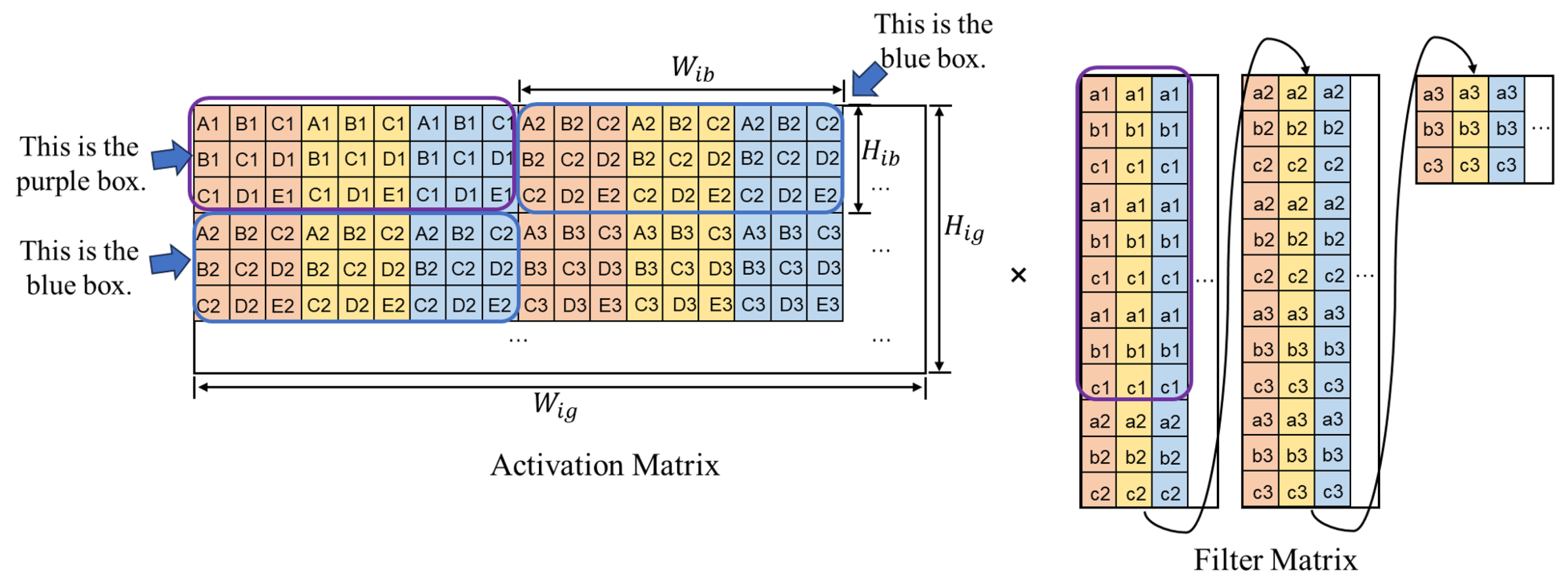
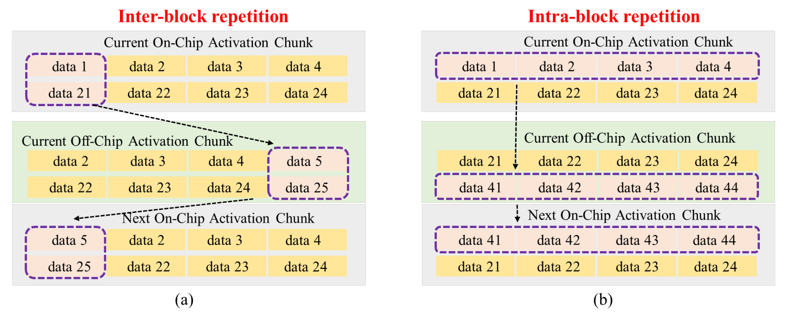
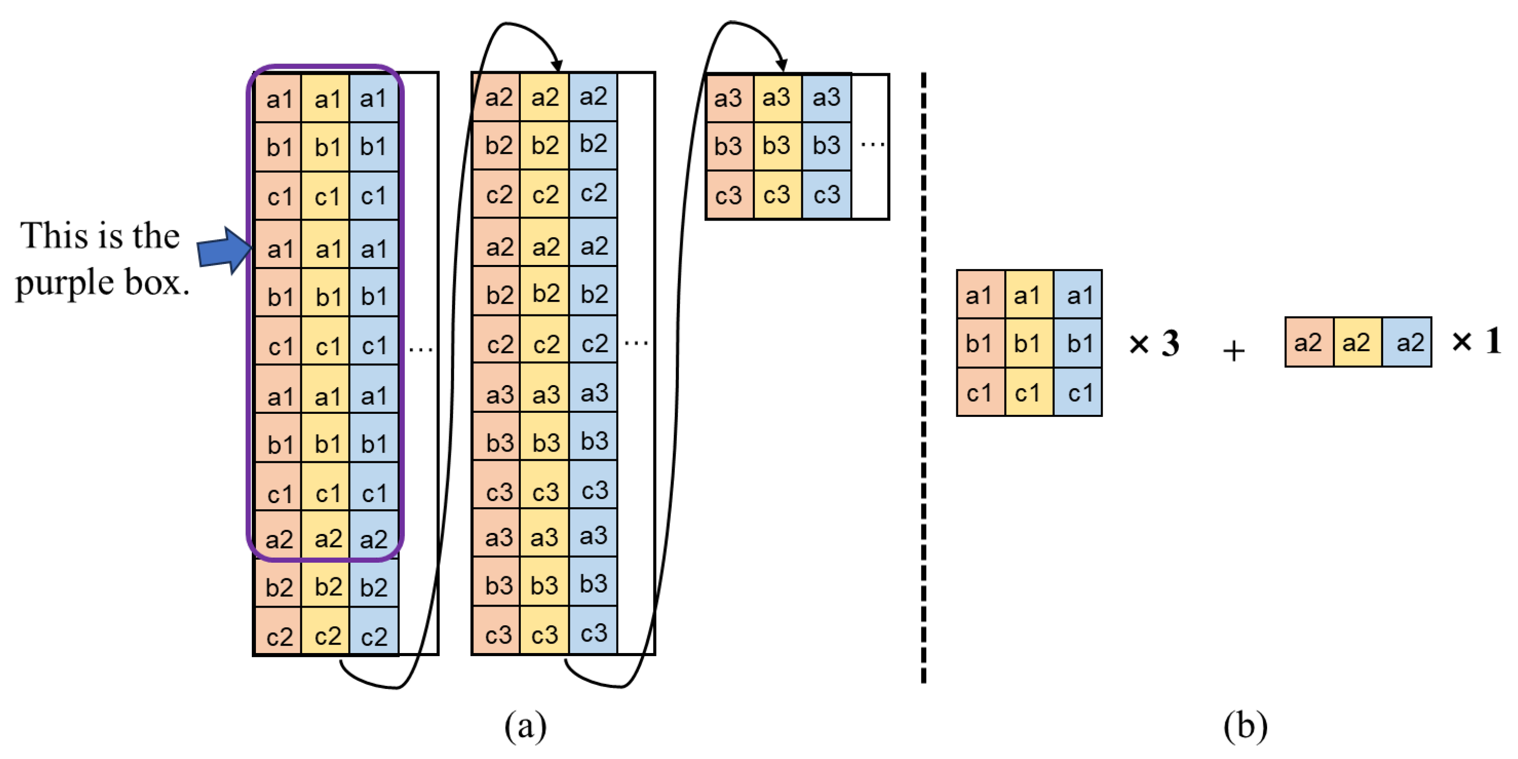
3.1. Data Repetition and Chunk Partition

Figure 2 illustrates the standard convolution based on activation and filter. Standard convolution is often computed through the GEMM approach, as shown in Figure 3, where GEMM expands the multi-channel activation into a two-dimensional Activation Matrix using the im2col method. Each Activation Matrix contains several blocks with a width of W i b and a height of H i b . The same applies to the filter. The calculation formulas for W i b and H i b are given by
W i b = W k × C i
H i b = W i W k S + 1
The calculation formulas for W i g and H i g are given by
W i g = C i × H k × W k
H i g = H i H k S + 1 × W i W k S + 1
The e x p r e s s i o n denotes the ceiling value of the expression and S denotes the stride of convolution.
Inter-block repetition refers to the data repetition between two adjacent diagonal blocks (e.g., the top-right and bottom-left blocks enclosed by the two blue boxes in Figure 3 are completely identical). Intra-block repetition refers to the data repetition between multiple rows in a single block (e.g., the block enclosed by the purple box contains B 1 , C 1 , and  D 1 , which appear repeatedly across the three rows). Considering the uncertainty of on-chip memory size and block size, prefetching complete blocks cannot always be ensured. In this study, the data to be prefetched each time are referred to as a chunk. The size of the chunk depends on the size of the On-Chip Activation Memory. The proposed method greedily prefetches chunks using two types of data repetition.
Based on the aforementioned description of data repetition and chunk partition, the prefetching route can be planned by leveraging the data repetition between chunks, thereby maximizing on-chip data reuse through data repetition, reducing unnecessary data movement between off-chip and on-chip memory, and enhancing computational efficiency.

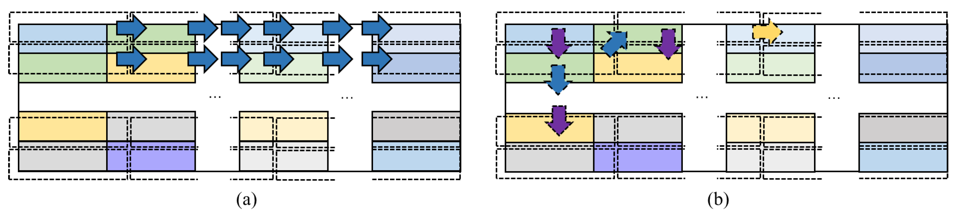
3.2. Prefetching Directions and Data Reuse

Leveraging data repetition and chunk partition, the Activation Matrix is partitioned into several chunks that exhibit inter-block repetition and intra-block repetition. In traditional prefetch, these data repetitions are overlooked, whereas the greedy prefetch capitalizes on these repetitions to plan the prefetching route. Concurrently, an analysis is conducted on the impact of prefetching activation chunks in different directions on the reuse of Filter Chunks.
Figure 4a shows the traditional prefetch strategy, which prefetches chunks row by row in the Activation Matrix. This is the common loop block strategy. This results in highly inefficient data reuse. To decrease insignificant off-chip data accesses, we propose greedy prefetch, shown in Figure 4b, which takes into account two types of repetition. In inter-block repetition, while achieving perfect prefetching of blocks is not feasible, there may be data repetition in diagonally prefetching chunks. Therefore, diagonally prefetching chunks is considered. Similarly, as the preceding and succeeding chunks may span across a block, resulting in intra-block repetition, vertically prefetching chunks is also considered.
Inter-block repetition and intra-block repetition can deduce the necessity of diagonal prefetching and vertical prefetching, respectively. However, to establish a comprehensive prefetching route, the incorporation of horizontal prefetching is also essential, as depicted in Figure 5. In Figure 5(a.1), the greedy prefetching route for 4 chunks is planned, and in Figure 5(a.2), an abstract geometric representation is used with the starting chunk as the source and the ending chunk as the destination. The greedy prefetching route between these 4 chunks only requires vertical and diagonal prefetching. In Figure 5(b.1), the greedy prefetching route for 6 chunks is planned and the same operation as Figure 5(a.2) is performed in Figure 5(b.2). Since chunk6 cannot connect to chunk3 using vertical or diagonal prefetching, horizontal prefetching must be introduced to connect chunk3 and chunk6, even though there is no data repetition between chunk3 and chunk6.
Subsequent analysis focuses on the potential data reuse of Filter Chunks corresponding to the prefetching of activation chunks in diagonal, vertical, and horizontal directions. As depicted in Figure 6b, GEMM can be decomposed into the multiplications of several strips within the activation and filter, and the multiplication of strips is equivalent to several multiplications of chunks. Figure 6a illustrates three cases of prefetching in greedy prefetch, where activation chunks are vertically, diagonally, or horizontally prefetched from off-chip memory. It is observed that these three methods of prefetching the activation chunks enable complete reuse of the filter chunk.

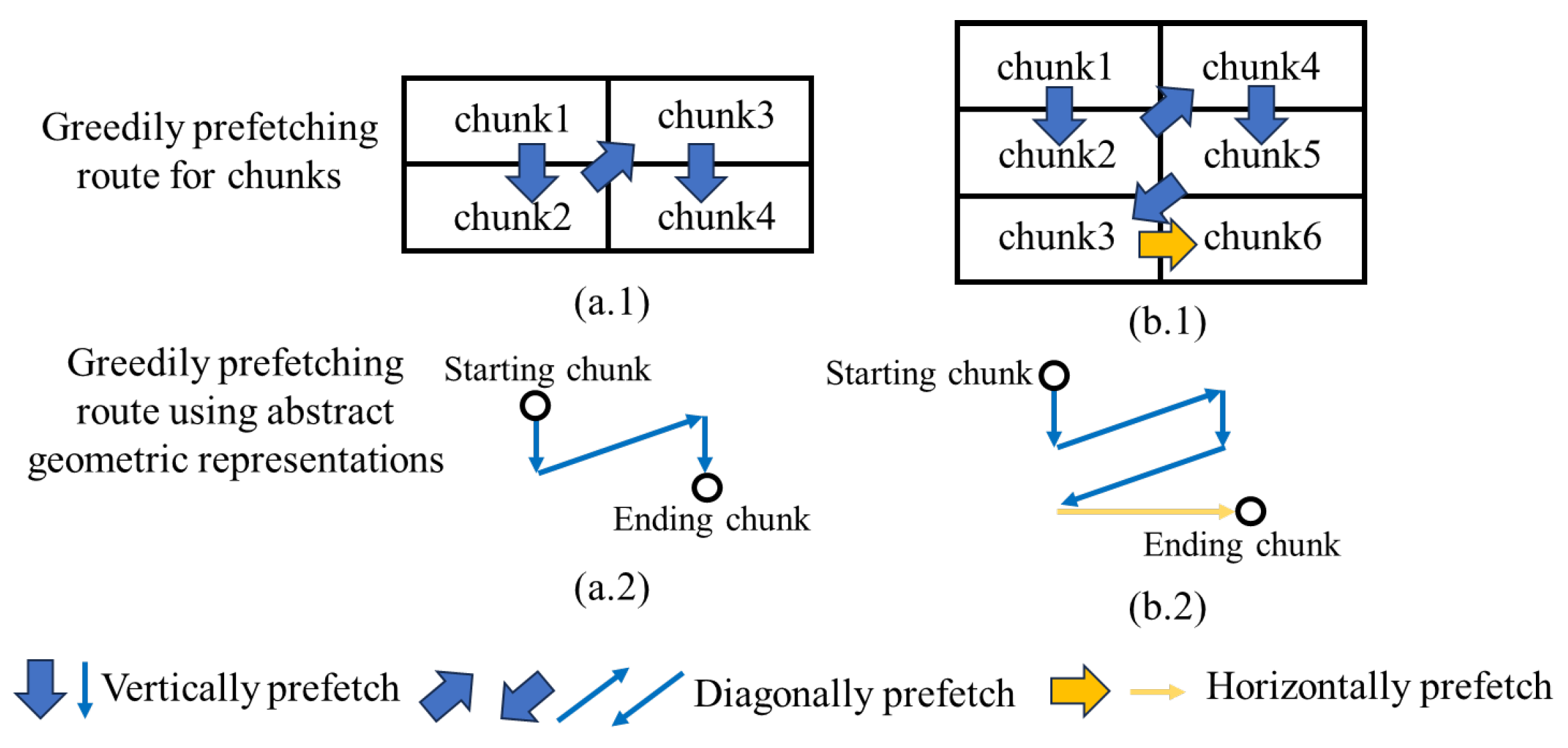
3.3. Greedily Scheduling Algorithm

3.3.1. Greedily Scheduling Algorithm for Activation

To acquire the prefetching route for the activation chunks, the Activation Matrix is initially partitioned into multiple chunks. Subsequently, Algorithm 1 (also known as the Greedily Scheduling Algorithm) is employed to connect all these chunks. The Greedily Scheduling Algorithm not only plans the prefetching route but also generates Replacing Index and Converting Index. To avoid abruptness when directly presenting the algorithm’s pseudocode, the process of obtaining Replacing Index and Converting Index based on the Current Off-Chip Activation Chunk and Current On-Chip Activation Chunk under two types of data repetition is first explained.
In Figure 7a, the same data in the Current On-Chip Activation Chunk and Current Off-Chip Activation Chunk include data2, data3, data4, data22, data23, and data24. Therefore, only data5 and data25 from the Current Off-Chip Activation Chunk need to replace data1 and data21 from the Current On-Chip Activation Chunk. The Replacing Index is recorded as {4→1}, which signifies using the 4th column of the Current Off-Chip Activation Chunk to replace the 1st column of the Current On-Chip Activation Chunk. After the replacement is complete, the Current Off-Chip Activation Chunk is transformed into the Next On-Chip Activation Chunk. However, to correctly calculate the convolution, the data of the Next On-Chip Activation Chunk must be stored in the buffer of the computation array according to the data layout of the Current Off-Chip Activation Chunk. The Converting Index is recorded as {2,3,4,1}, which signifies reading data from the Next On-Chip Activation Chunk in the order of the 2nd, 3rd, 4th, and 1st columns and placing them into the buffer of the computation array.
Algorithm 1 Details of the Greedily Scheduling Algorithm for Activation.
Require: Height of Activation Chunk Matrix H, Width of Activation Chunk Matrix W
Ensure: Repetition Matrix D 0 H × W , H × W
 # Step 1. Fill the D.
for w 1 to W do
  for h 1 to H do
   # Find the repetitive data in each two chunks.
   # Fill the number of repetitive data in D.
  end for
end for
Ensure: Prefetching Route R, Chunk set C { c 0 , c 1 , , c H × W } , Set of converting index S c , Converting index C i , Set of replacing index S r , Replacing index R i , Current Off-Chip Activation Chunk C o f f , Current On-Chip Activation Chunk C o n
 # Step 2. Find the R, Sc, and Sr.
 # Append c0 to R , delete c0 in C, C o f f c 0 and C o n c 0
while C do
  # Find the maximal number of repetition in neighboring off-chip
   chunks according to D.
  # Find the off-chip chunk Cmax with maximal repetition for C o n .
  # Find the R i of non-repetitive data between Cmax and C o n .
  # Transform the Cmax into Next On-Chip Activation Chunk Cnmax.
  # Find the C i between Cmax and Cnmax .
  # Append Cmax to R and delete Cmax in C.
  # C o n C n m a x and C o f f C m a x .
  # Append R i to S r and R i .
  # Append C i to S c and C i .
end while
In Figure 7b, the same data in the Current On-Chip Activation Chunk and Current Off-Chip Activation Chunk include data21, data22, data23, and data24. Therefore, only data41, data42, data43, and data44 from the Current Off-Chip Activation Chunk need to replace data1, data2, data3, and data4 from the Current On-Chip Activation Chunk. The Replacing Index is recorded as {2→1}, which signifies using the 2nd row of the Current Off-Chip Activation Chunk to replace the 1st row of the Current On-Chip Activation Chunk. After the replacement is complete, the Current Off-Chip Activation Chunk is transformed into the Next On-Chip Activation Chunk. However, to correctly calculate the convolution, the data of the Next On-Chip Activation Chunk must be stored in the buffer of the computation array according to the data layout of the Current Off-Chip Activation Chunk. The Converting Index is recorded as {2,1}, which signifies reading data from the Next On-Chip Activation Chunk in the order of the 2nd and 1st rows and placing them into the buffer of the computation array.
In summary, for the Current On-Chip Activation Chunk and Current Off-Chip Activation Chunk that exhibit both types of data repetition, it is only necessary to save the horizontal and vertical replacement indices in the Replacing Index, and similarly, save the horizontal and vertical reading orders in the Converting Index.
The Replacing Index and Converting Index for adjacent two activation chunks before and after prefetching have been detailed, thus allowing for easy generalization of this step to the Replacing Index and Converting Index for multiple activation chunks. In Algorithm 1, specifically, in the first step, according to the size of on-chip memory, the Activation Matrix is divided into several chunks, totaling H × W . It is necessary to calculate the number of data repetitions between any two chunks and fill them into the repetition matrix D.
Nevertheless, establishing the global optimal prefetching route poses a significant challenge. It is not anticipated that the optimal solution will be attained through the exploration of all potential prefetching routes. Instead of finding the optimal solution, greedy prefetch is chosen. The greedy prefetching route is solved based on the repetition matrix. The chunk located at the top left corner of the activation is selected as c 0 , and the next chunk is greedily determined by the highest data repetition between chunks in three prefetching directions. This methodology is dependable because repetitive data arising from the sliding of convolution are localized, resulting in significant computational cost reduction. This aligns with the goal of swiftly designing dataflow. The set of Replacing Index is established by comparing non-repetitive data between C m a x and the Current On-Chip Activation Chunk C o n . This enables the overwriting of unused on-chip chunk data with non-repetitive off-chip chunk data. For example, in Figure 7a, the Replacing Index {4→1} indicates that the Current Off-Chip Activation Chunk’s 4th column (data5 and data25) overwrites the Current On-Chip Activation Chunk’s 1st column (data1 and data21). The set of Converting Index is derived by comparing C m a x and C n m a x to revert on-chip activation chunks to GEMM format. In Figure 7a, for convolution in the correct layout, chunks are fed into the Systolic Array, ensuring that the Next On-Chip Activation Chunk is read in the order specified by the Converting Index {2,3,4,1}, which means reading from column 2 to column 4 and then back to column 1. A similar analysis can be conducted for Figure 7b. Thus, only a horizontal and vertical Replacing Index and Converting Index are needed to populate and restore chunks to GEMM format.

3.3.2. Greedily Scheduling Algorithm for Filter

To facilitate the explanation of how the Greedily Scheduling Algorithm for Filter obtains reused convolution kernel data, starting data, and repetition counts, Figure 8a displays the expanded Filter Matrix, where the purple box represents the Filter Chunk. Such a Filter Chunk requires the storage of 30 pieces of data. Figure 8b illustrates the elements contained within the purple box representing the Filter Chunk, where the reused convolution kernel data include all a1, b1, and c1 with red, yellow, and blue backgrounds, as well as a2 with red, yellow, and blue backgrounds; the starting data are the red a1, and the repetition counts are 3 and 1, respectively. By doing so, only 15 pieces of data need to be stored. Compared to the method in Figure 8a, this approach reduces the storage requirement by half, and the effect is more pronounced as the size of the Filter Chunk increases. However, when computing the convolution, it is still necessary to restore the data stored as in Figure 8b into the Filter Chunk and place them into the buffer of the Systolic Array.
As shown in Algorithm 2, only a sequential traversal of the Filter Chunk is required, with the first value being taken as the starting data. Subsequently, the reused convolution kernel data and its frequency are continuously tallied and stored as key-value pairs in D r . Ultimately, all keys from D r are placed into S r , and the non-repeating values from D r are placed into S c .
Algorithm 2 Details of the Greedily Scheduling Algorithm for the filter.
Require: Height of Filter Chunk H, Width of Filter Chunk W, Filter Chunk F C
Ensure: Set of reused convolution kernel data S r , Starting data S d 0 , Set of repetition counts
S c , Directory of reused convolution kernel data D r
 # Task: Find the above variables.
S d F C ( 0 , 0 )
for h 1 to H do
  for w 1 to W do
   # If F C (h, w) is not in D r , then append F C (h, w) as a key to D r .
    Otherwise, do not append F C (h, w) to D r .
   # Find the value of F C (h, w) in D r and value ← value + 1.
  end for
end for
 # Select the keys of D r and append keys to S r .
 # Select the values of D r , filter out distinct values, and append values to S c .

4. The Part of Hardware
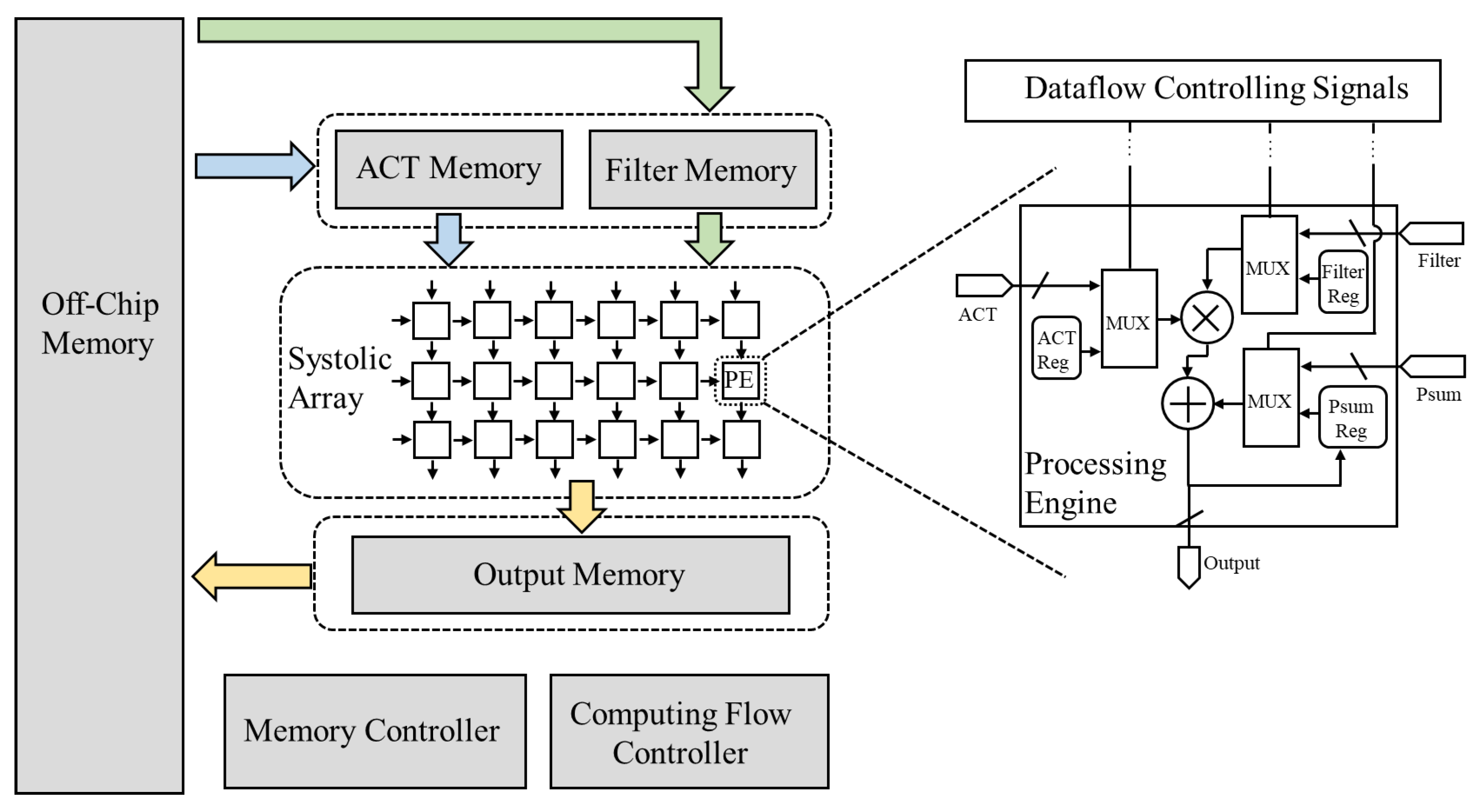
4.1. Architecture

To evaluate the proposed greedy prefetching, the accelerator architecture depicted in Figure 9 is utilized. The on-chip system consists of activation/filter/output memory, Systolic Array, memory controller, and computing flow controller. The memory controller is used to manage storage by executing instructions. The computing flow controller is used to manage the launching of the Systolic Array and generate the dataflow-controlling signals. In order to enable each Processing Element (PE) to support different modes of Systolic Arrays, the computing flow controller could generate dataflow-controlling signals to control the source of input data. For instance, the input stationary Systolic Array supports the reuse of input feature map data, with the dataflow-controlling signals continuously updating the filter by controlling the multiplexer (mux).

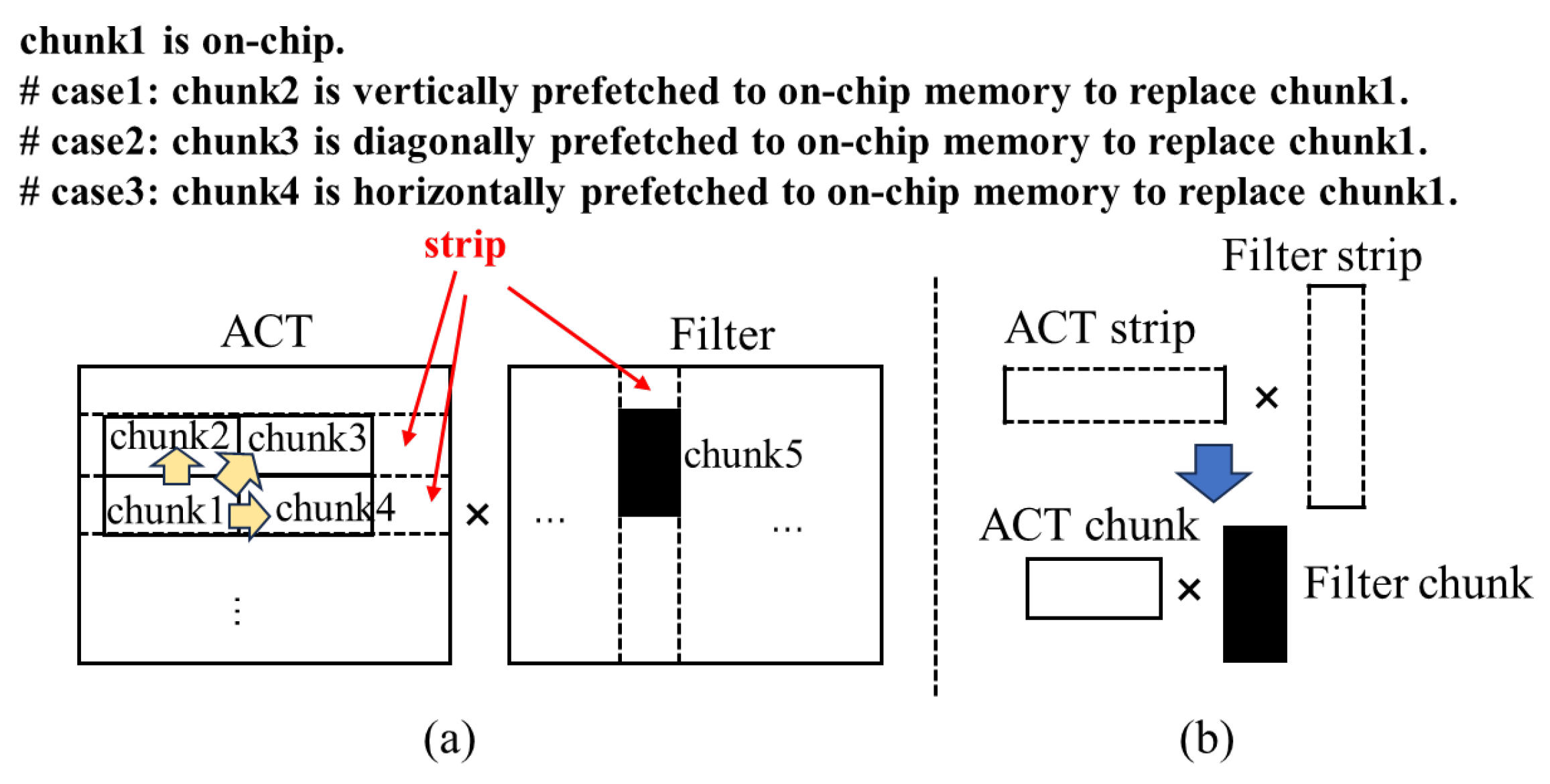
4.2. Chunk-Replacing Process

To ensure that activation chunks can be prefetched into on-chip memory and read out in a specific sequence to achieve correct convolution calculations, the Greedily Scheduling Algorithm for Activation in the software part outputs the prefetching route, Replacing Index, and Converting Index.
Figure 10 demonstrates the Chunk-Replacing Process and Chunk-Converting Process for activation. The assumed prefetching route is from chunk1 to chunk2, and then to chunk4. Hardware prefetches data according to the prefetching route, moving them from off-chip memory to On-Chip Activation Memory. This involves specifying the on-chip addresses to be overwritten and the non-repetitive data to be prefetched, which requires the Replacing Index. Taking Figure 7a as an example, let the Current Off-Chip Activation Chunk be chunk2 with a Replacing Index of {4→1}. It is necessary to replace data1 and data21 with data5 and data25 in sequence, as indicated in Figure 10 with the load instructions load mem [chunk2.data5] and load mem [chunk2.data25], where the mem addresses in these instructions are determined by the Replacing Index. The term mem refers to the On-Chip Activation Memory, and [chunk2.data5] signifies data5 of chunk2, with similar notation applied to others. Concurrently, the Converting Index needs to be stored in the On-Chip Activation Memory. Taking Figure 7a as an example, its Converting Index is {2,3,4,1}, thus requiring the storage of four index numbers. Four load instructions, load mem [chunk2.V0], load mem [chunk2.V1], load mem [chunk2.V2], and load mem [chunk2.V3], are used to store the four index numbers in the On-Chip Activation Memory, where the mem addresses can be determined by the Converting Index. [chunk2.V0] represents V0 of chunk2, with V0 assumed to be 2, and similarly, V1, V2, and V3 are assumed to be 3, 4, and 1, respectively.

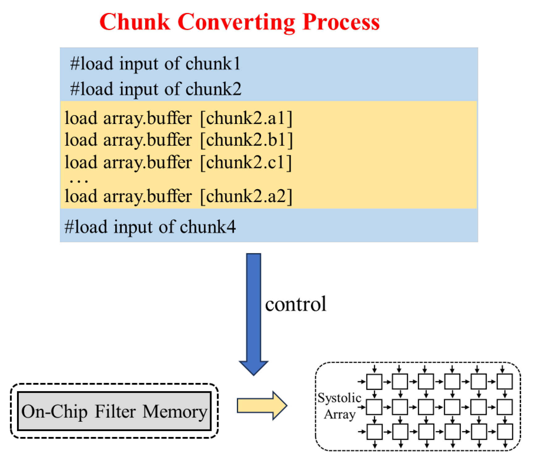
4.3. Chunk-Converting Process

4.3.1. Chunk-Converting Process for Activation

In Section 4.2, based on the prefetching route and Replacing Index, the off-chip activation chunks to be prefetched replace the on-chip activation chunks. In this section, an explanation is given on how to use Converting Index to read the data of the on-chip activation chunks in the correct order and store the data into the buffer of the Systolic Array, thereby driving the correct convolutional computation.
The hardware requires the Converting Index to restore the On-Chip Activation Chunk to the GEMM format of activation and place it into the buffer of the Systolic Array. Taking Figure 7a as an example, its Converting Index is {2,3,4,1}, and data are read in the order of the 2nd column, 3rd column, 4th column, and then the 1st column. In Figure 10, the instructions load array.buffer [chunk2.data2], load array.buffer [chunk2.data22], …, load array.buffer [chunk2.data5], and load array.buffer [chunk2.data25] utilize the Converting Index to transform addresses and read data in the correct sequence into the buffer of the Systolic Array. Here, array.buffer denotes the buffer of the Systolic Array, and [chunk2.data2] represents data2 of chunk2, with similar notation for the rest.
The output obtained from the Systolic Array sequentially enters the On-Chip Output Memory and off-chip memory, with the entire process being both memory-visible and programmable.

4.3.2. Chunk-Converting Process for Filter
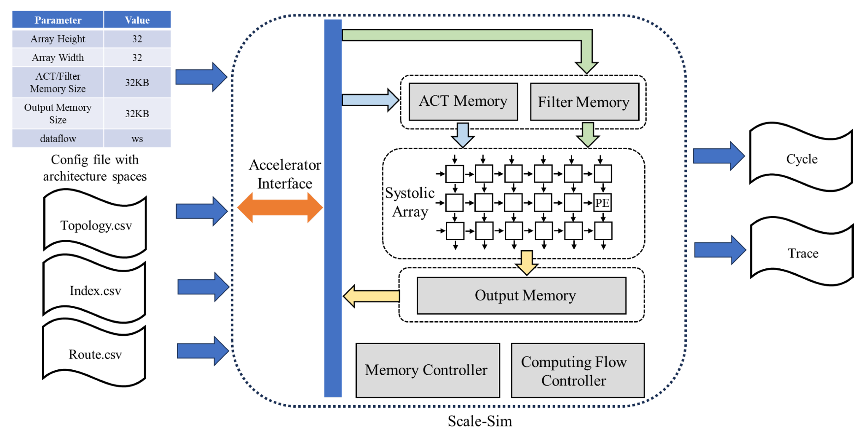
Unlike the Chunk-Converting Process for activation, filters require reused convolution kernel data, starting data, and repetition counts. Figure 11 illustrates the Chunk-Converting Process for filters. Taking the chunk indicated by the purple box in Figure 8 as an example, its reused convolution kernel data include all a1, b1, and c1 with red, yellow, and blue backgrounds, as well as a2 with red, yellow, and blue backgrounds; the starting data are the red a1, and the repetition counts are 3 and 1, respectively. Given that the aforementioned prefetching route is assumed to be from chunk1 to chunk2 and then to chunk4, and observing the situation of chunk2, the following instructions are used to repeatedly read all a1, b1, and c1 with red, yellow, and blue backgrounds until the repetition counts for this batch of data are exhausted: load array.buffer [chunk2.a1], load array.buffer [chunk2.b1], load array.buffer [chunk2.c1], etc., with the first read a1 being the red one. Here, array.buffer denotes the buffer in the Systolic Array, and [chunk2.a1] represents a1 in chunk2. Subsequently, the instruction load array.buffer [chunk2.a2] is used to repeatedly load a2 with red, yellow, and blue backgrounds until the repetition counts for this batch of data are exhausted.

5. Implementation

Utilizing the modified Scale-Sim [29], the performance of greedy prefetch is assessed with Yolo-Tiny-v4, MobileNet, and ResNet34, which are common CNNs for edge inference due to their low parameter counts. The Scale-Sim employs an address-tracking mode to simulate the behavior of the program on the hardware architecture. As shown in Figure 12, the simulator configures parameters such as the Systolic Array sizes, dataflows, and on-chip memory capacity via configuration files. It also inputs the topology parameters and indices of chunks, as well as the prefetch route. In this way, the simulator can output metrics such as cycles. By enabling trace output, the system can be tracked. The indices and prefetch routes are calculated using a local platform rather than simulator.
The memory read/write energy data are sourced from [24], and the activation/filter on-chip memory is allocated 32 KB, with 4 KB reserved for index. A comparison is also made between the greedy prefetch (GP) and other optimizations such as hybrid stationary dataflow (HS), dynamic memory allocation (MA), and NVM substitution. Magnetoresistive Random-access Memory (MRAM) is selected as the NVM, matching the area of 32 KB SRAM@28nm process which provides approximately 101 KB storage [30], with 12 KB allocated for index. Consequently, MRAM is employed as the on-chip memory for activations and filters because of the high memory demands caused by im2col. SRAM is still utilized for output. The models are quantized into 8 bits. The scale of the Systolic Array is 32 × 32 PEs unless otherwise specified.

6. Results

6.1. The Effectiveness of Greedy Prefetch

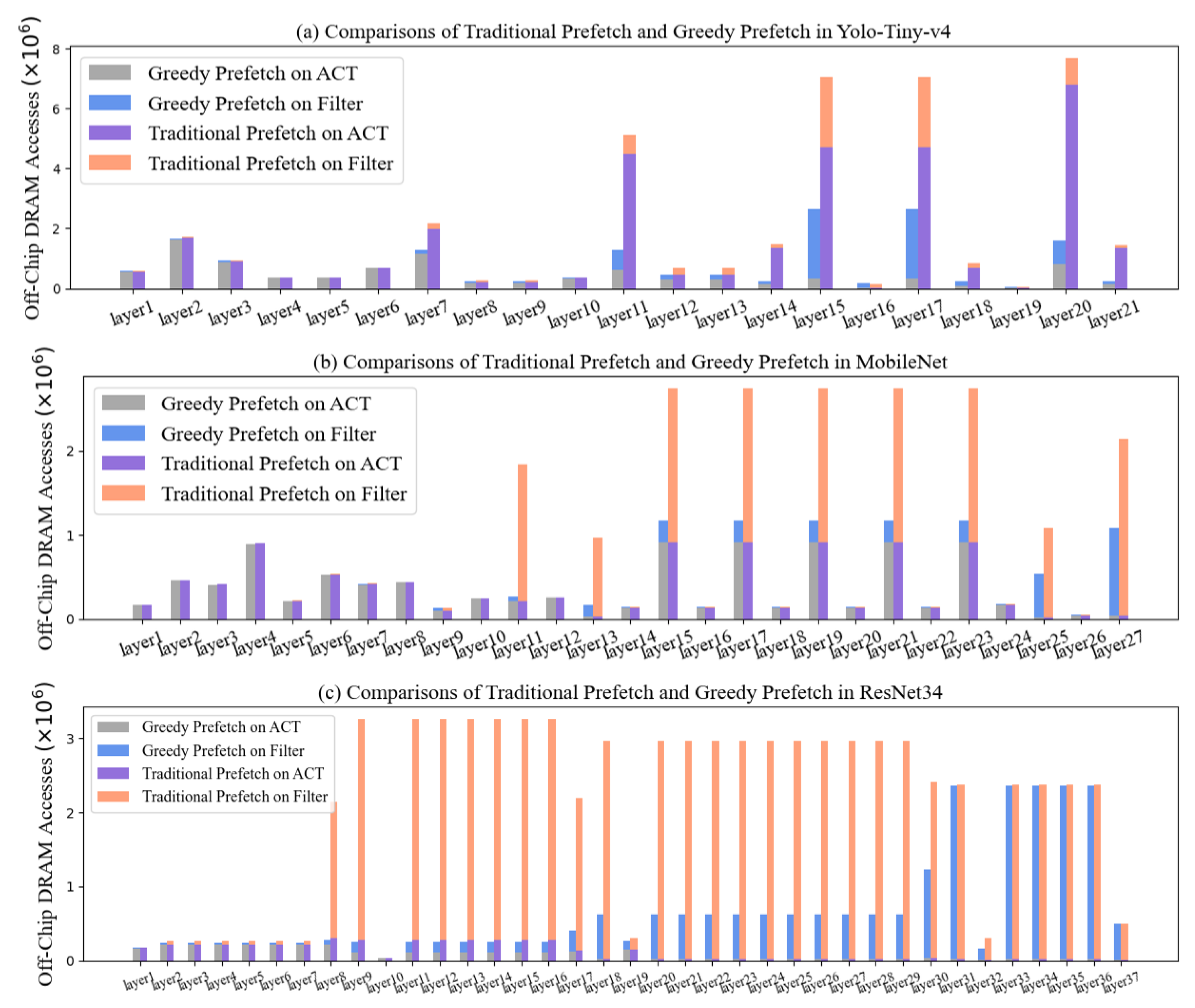
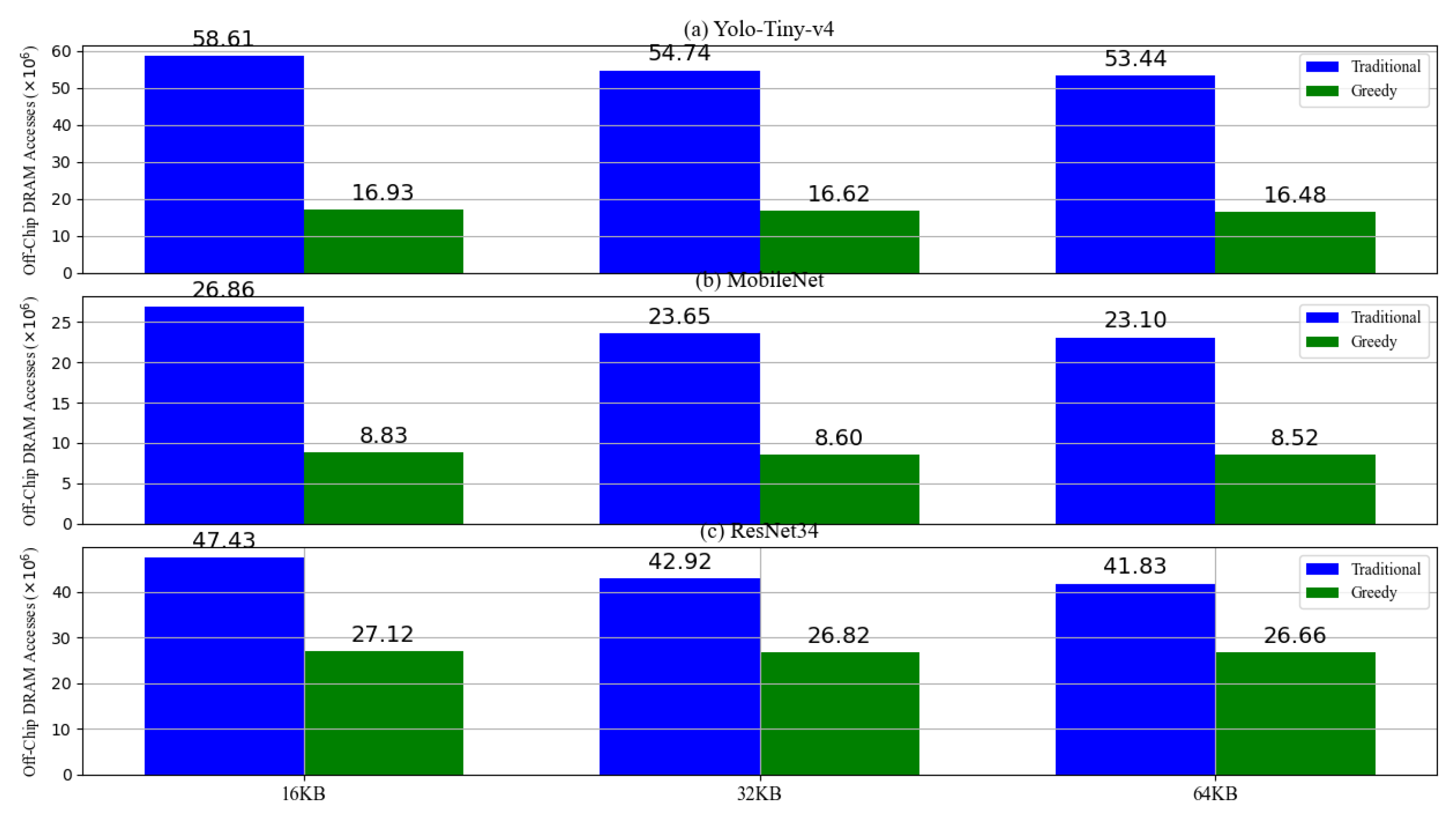
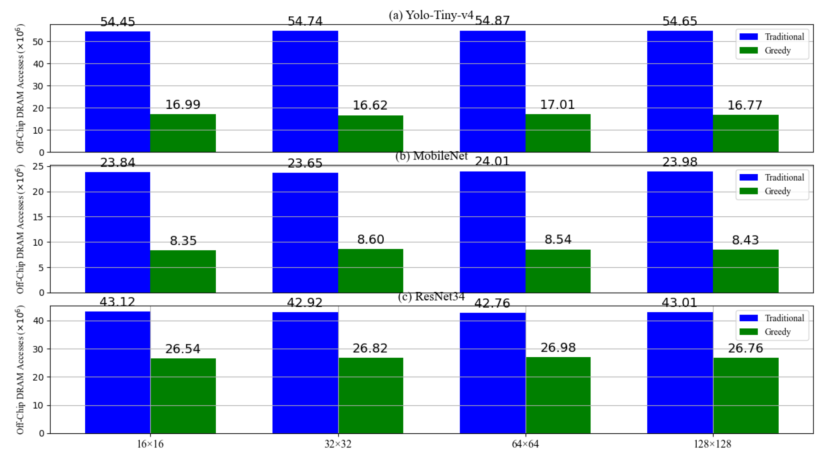
6.1.1. The Off-Chip Memory Accesses of Greedy Prefetch

In Figure 13 (the ACT is used to denote activation), compared to traditional prefetch (TP), GP reduces off-chip memory accesses for Yolo-Tiny-v4 by 0.91× on average (max 4.62×), MobileNet by 1.28× (max 6.09×), and ResNet34 by 2.60× (max 12.25×), showing its effectiveness in reducing off-chip memory accesses. The results demonstrate that GP achieves fewer off-chip memory accesses. In deeper network layers with larger filters and more output channels, GP effectively minimizes off-chip memory accesses for filters due to data reuse. Similarly, with large activation sizes and numerous output channels, GP also reduces off-chip memory accesses for activations by increasing the reuse frequency of repetitive data within larger Activation Matrixes and more chunks.
The effectiveness of greedy prefetching under various on-chip memory capacities for activations and filters has been tested using a 32 × 32 Systolic Array and a hybrid stationary dataflow. As demonstrated in Figure 14, the results indicate that greedy prefetching outperforms traditional prefetching in reducing off-chip memory accesses. Specifically, on Yolo-Tiny-v4, greedy prefetching achieves a maximum reduction to 71.1% of the traditional scheme; on MobileNet, to 67.1%; and on ResNet34, to 42.8%. As the on-chip memory capacity for activations and filters increases, both traditional and greedy prefetching exhibit reduced off-chip memory accesses. This improvement is attributed to the increased capacity of on-chip memory to store more activations and filters, thereby enabling greater reuse of on-chip data for both prefetching modes.
An on-chip memory capacity of 32 KB for activations and filters has been adopted in conjunction with a hybrid stationary dataflow to evaluate the efficacy of greedy prefetching across various Systolic Array sizes. As depicted in Figure 15, the results demonstrate the effectiveness of greedy prefetching. Specifically, off-chip memory accesses have been reduced to 71.1% of the traditional scheme for Yolo-Tiny-v4, 67.1% for MobileNet, and 42.8% for ResNet34. Variations in Systolic Array scales have not significantly impacted off-chip memory accesses for either prefetching strategy, primarily due to the constant on-chip memory capacity. Changes in Systolic Array size lead to on-chip memory accommodating data from different partitions of the neural network, resulting in discrepancies in on-chip data reuse compared to before the array size change. However, statistical analysis indicates that these differences do not markedly result in drastic fluctuations in off-chip memory accesses.

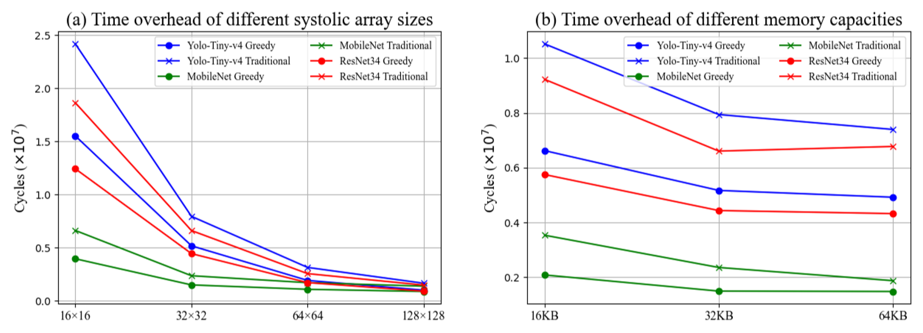
6.1.2. The Time Overhead of Greedy Prefetch

The same on-chip memory capacity for activations and filters, coupled with a hybrid stationary dataflow, has been employed to test the clock cycles under varying Systolic Array sizes and two distinct prefetching methods. As illustrated in Figure 16a, the experimental results demonstrate that greedy prefetching yields fewer cycles compared to traditional prefetching, with a reduction that increases with the size of the array. Specifically, the maximum reduction achieved is to 39.4% of the traditional scheme for Yolo-Tiny-v4, 40.3% for MobileNet, and 38.5% for ResNet34.
A consistent Systolic Array size and hybrid stationary dataflow have been utilized to test the cycles under varying on-chip memory capacities for activations and filters, alongside two distinct prefetching methods, as depicted in Figure 16b. The experimental outcomes indicate that the cycles required for operation with greedy prefetching remain fewer than those with traditional prefetching as the storage capacity varies. The reduction in cycles is less pronounced when increasing from 32 KB to 64 KB compared to the increase from 16 KB to 32 KB, which may be associated with the on-chip memory capacity of 32 KB already sufficiently meeting the demands of the 32 × 32 array scale.
An analysis of the cycles required for chunk replacing and chunk converting has been conducted, as depicted in Figure 17. The average proportion of chunk replacing in the total time for the three networks stands at 1.2%, while the average proportion for chunk converting is 9.0%. This is attributed to the fact that chunk replacing necessitates the prefetching and overwriting of data in the on-chip storage that will not be utilized in the future; reused data, however, do not require prefetching, although chunk replacing necessitates the restoration of all data in the GEMM format. In this context, the chunk replacing only accounts for the portion of indices utilized; as for the Systolic Array, a piece of data is computed concurrently with the retrieval of another from the on-chip storage, resulting in an overlap between the data retrieval and computation phases. This overlapping period is not included in the chunk-replacing cycles.

6.2. Comparison with Other Optimizations

In Figure 18, comparisons are made between the optimization levels of GP (greedy prefetch) and TP (traditional prefetch) (the first and fourth columns of each diagram), hybrid stationary dataflow (HS) and weight stationary dataflow (WS) (the first and second columns of each diagram), and memory allocation (MA) and memory fixed (MF) (the first and third columns of each diagram). MA adaptively assigns memory for activations and filters in activation and filter memory based on their parameters, while MF employs a fixed memory allocation for them. Compared with TP, GP achieves a reduction in off-chip memory accesses in benchmarks by factors of 1.37×, 1.03×, and 0.13×, respectively. It is observed that GP and HS demonstrate significant optimization effects across the three networks, whereas the optimization effect of MA is less pronounced. In the first and fifth columns of each diagram, compared to the dataflow composed of the baseline (WS + MF + TP), the dataflow that incorporates the three optimizations (HS + MA + GP) significantly reduces off-chip memory accesses.

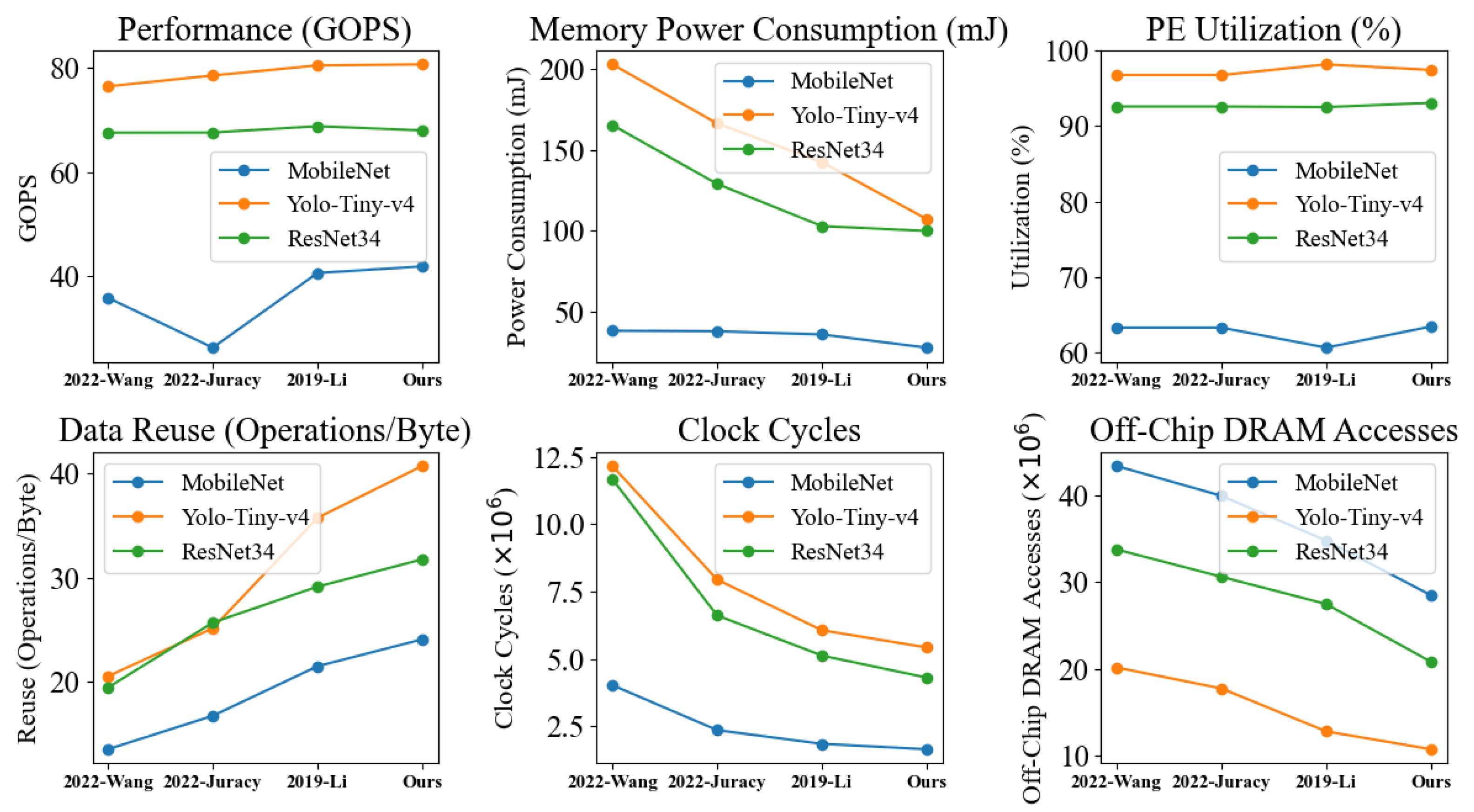
6.3. Comparison with Recent Works

Based on the aforementioned experimental findings, a new deployment strategy is simulated by combining the four optimizations. To ensure a fair comparison with other deployment schemes, the same memory area and scale for the Systolic Array are maintained. In Table 2, three strategies previously discussed in Section 2 (Related Works) are selected. The results are depicted in Figure 19. The clock frequency is assumed to be 100 MHz.
In comparison to other strategies, our combined strategy shows notable improvements. The proposed combined strategy outperforms in data reuse, achieving a maximum improvement of 1.98×. Additionally, the minimal PE utilization gap stems from Systolic Arrays’ method of segmenting and mapping matrix multiplications along their dimensions. Most of the time, all PEs are utilized, with only occasional idleness. Despite varying dataflows, the average PE utilization across different Systolic Arrays is nearly the same.
Figure 19 allows for a fair comparison and validation of its effectiveness on the same platform by obtaining the array size, dataflow, and memory configuration from the literature. To provide a more comprehensive comparison with other schemes, detailed comparisons are presented in Table 3. Our work is not mutually exclusive with other works, and other works can employ greedy prefetching to further reduce the number of off-chip memory accesses.

7. Conclusions

This paper proposes a greedy prefetching technique, which effectively reduces the number of off-chip memory accesses during the inference process of CNNs, outperforming other data reuse optimization methods. Although the experimental process is based on a simulator and does not involve an application-specific integrated circuit design, thus failing to provide a precise evaluation of the greedy prefetching effect, the simulator does not affect the validation of the greedy prefetching and its expected effects, which can guide the design of ASICs and their software toolchains.

Author Contributions

Conceptualization, D.Y. and L.C.; methodology, D.Y.; software, D.Y.; validation, D.Y.; formal analysis, D.Y. and L.C.; investigation, D.Y.; resources, L.C.; writing—original draft preparation, D.Y.; writing—review and editing, L.C.; visualization, D.Y.; supervision, L.C.; project administration, L.C.; funding acquisition, L.C. All authors have read and agreed to the published version of the manuscript.

Funding

This research was funded by the Informatization Project of Chinese Academy of Sciences under Grant CAS-WX2021SF-0113 (corresponding author: Lan Chen).

Institutional Review Board Statement

Not applicable.

Informed Consent Statement

Not applicable.

Data Availability Statement

Publicly available datasets were analyzed in this study. These data can be found here: https://cocodataset.org/ (accessed on 21 February 2015) for the COCO dataset, https://github.com/pytorch/pytorch (accessed on 5 June 2020) for ResNet34 and MobileNet, and https://github.com/ultralytics/ultralytics (accessed on 26 December 2020) for Yolo-Tiny-v4.

Acknowledgments

The first author, D.Y., hereby acknowledges the Institute of Microelectronics of the Chinese Academy of Sciences (IMECAS) and the EDA Center.

Conflicts of Interest

The authors declare no conflicts of interest.

References

  1. Ashtiani, F.; Geers, A.J.; Aflatouni, F. An on-chip photonic deep neural network for image classification. Nature 2022, 606, 501–506. [Google Scholar] [CrossRef]
  2. Chen, K.; Chen, B.; Liu, C.; Li, W.; Zou, Z.; Shi, Z. Rsmamba: Remote sensing image classification with state space model. IEEE Geosci. Remote Sens. Lett. 2024, 21, 8002605. [Google Scholar] [CrossRef]
  3. Lu, S.; Zhang, M.; Huo, Y.; Wang, C.; Wang, J.; Gao, C. SSUM: Spatial–Spectral Unified Mamba for Hyperspectral Image Classification. Remote Sens. 2024, 16, 4653. [Google Scholar] [CrossRef]
  4. Yeh, C.H.; Lin, C.H.; Kang, L.W.; Huang, C.H.; Lin, M.H.; Chang, C.Y.; Wang, C.C. Lightweight deep neural network for joint learning of underwater object detection and color conversion. IEEE Trans. Neural Netw. Learn. Syst. 2021, 33, 6129–6143. [Google Scholar] [CrossRef]
  5. Chen, Q.; Liu, Z.; Zhang, Y.; Fu, K.; Zhao, Q.; Du, H. RGB-D salient object detection via 3D convolutional neural networks. In Proceedings of the AAAI Conference on Artificial Intelligence (AAAI), Vancouver, BC, Canada, 2–9 February 2021; pp. 1063–1071. [Google Scholar]
  6. Li, X.; Deng, J.; Fang, Y. Few-shot object detection on remote sensing images. IEEE Trans. Geosci. Remote Sens. 2021, 60, 5601614. [Google Scholar] [CrossRef]
  7. Zhao, Y.; Lv, W.; Xu, S.; Wei, J.; Wang, G.; Dang, Q.; Chen, J. Detrs beat yolos on real-time object detection. In Proceedings of the IEEE/CVF Conference on Computer Vision and Pattern Recognition (CVPR), Seattle, WA, USA, 17–21 June 2024; pp. 16965–16974. [Google Scholar]
  8. Cheng, T.; Song, L.; Ge, Y.; Liu, W.; Wang, X.; Shan, Y. Yolo-world: Real-time open-vocabulary object detection. In Proceedings of the IEEE/CVF Conference on Computer Vision and Pattern Recognition (CVPR), Seattle, WA, USA, 17–21 June 2024; pp. 16901–16911. [Google Scholar]
  9. Rios, M.; Ponzina, F.; Levisse, A.; Ansaloni, G.; Atienza, D. Bit-line computing for CNN accelerators co-design in edge AI inference. IEEE Trans. Emerg. Topics Comput. 2023, 11, 358–372. [Google Scholar] [CrossRef]
  10. Pham, N.S.; Suh, T. Optimization of Microarchitecture and Dataflow for Sparse Tensor CNN Accelerator. IEEE Access 2023, 11, 108818–108832. [Google Scholar] [CrossRef]
  11. Kim, V.H.; Choi, K.K. A reconfigurable CNN-based accelerator design for fast and energy-efficient object detection system on mobile FPGA. IEEE Access 2023, 11, 59438–59445. [Google Scholar] [CrossRef]
  12. Zhou, Y.; Yang, M.; Guo, C.; Leng, J.; Liang, Y.; Chen, Q.; Zhu, Y. Characterizing and demystifying the implicit convolution algorithm on commercial matrix-multiplication accelerators. In Proceedings of the 2021 IEEE International Symposium on Workload Characterization (IISWC), San Jose, CA, USA, 31 October–4 November 2021; pp. 214–225. [Google Scholar]
  13. Umuroglu, Y.; Fraser, N.J.; Gambardella, G.; Blott, M.; Leong, P.; Jahre, M.; Vissers, K. Finn: A framework for fast, scalable binarized neural network inference. In Proceedings of the 2017 ACM/SIGDA International Symposium on Field-Programmable Gate Arrays (FPGA), Monterey, CA, USA, 26–28 February 2017; pp. 65–74. [Google Scholar]
  14. Islam, M.N.; Shrestha, R.; Chowdhury, S.R. Energy-Efficient and High-Throughput CNN Inference Engine Based on Memory-Sharing and Data-Reusing for Edge Applications. IEEE Trans. Circuits Syst. I Reg. Pap. 2024, 71, 3189–3202. [Google Scholar] [CrossRef]
  15. Wang, C.; Wang, Z.; Li, S.; Zhang, Y.; Shen, H.; Huang, K. EWS: An Energy-Efficient CNN Accelerator with Enhanced Weight Stationary Dataflow. IEEE Trans. Circuits Syst. II Express Briefs 2024, 71, 3478–3482. [Google Scholar] [CrossRef]
  16. Weerasena, H.; Mishra, P. Revealing CNN architectures via side-channel analysis in dataflow-based inference accelerators. ACM Trans. Embedded Comput. Syst. 2024, 23, 1–25. [Google Scholar] [CrossRef]
  17. Chen, Y.H.; Krishna, T.; Emer, J.S.; Sze, V. Eyeriss: An energy-efficient reconfigurable accelerator for deep convolutional neural networks. IEEE J. Solid-State Circuits 2016, 52, 127–138. [Google Scholar] [CrossRef]
  18. Wang, X.; Tian, T.; Zhao, L.; Wu, W.; Jin, X. Exploration of balanced design in resource-constrained edge device for efficient CNNs. IEEE Trans. Circuits Syst. II Express Briefs 2022, 69, 4573–4577. [Google Scholar] [CrossRef]
  19. Jouppi, N.P.; Young, C.; Patil, N.; Patterson, D.; Agrawal, G.; Bajwa, R.; Bates, S.; Bhatia, S.; Boden, N.; Borchers, A.; et al. In-Datacenter Performance Analysis of a Tensor Processing Unit. ACM J. Emerg. Technol. Comput. Syst. 2017, 45, 1–12. [Google Scholar]
  20. Kim, M.; Seo, J.S. An energy-efficient deep convolutional neural network accelerator featuring conditional computing and low external memory access. IEEE J. Solid-State Circuits 2020, 56, 803–813. [Google Scholar] [CrossRef]
  21. Juracy, L.R.; Amory, A.M.; Moraes, F.G. A comprehensive evaluation of convolutional hardware accelerators. IEEE Trans. Circuits Syst. II Express Briefs 2022, 70, 1149–1153. [Google Scholar] [CrossRef]
  22. Du, Z.; Fasthuber, R.; Chen, T.; Ienne, P.; Li, L.; Luo, T.; Feng, X.; Chen, Y.; Temam, O. ShiDianNao: Shifting Vision Processing Closer to the Sensor. In Proceedings of the 42nd Annual International Symposium on Computer Architecture (ISCA), Portland, OR, USA, 13–17 June 2015; pp. 92–104. [Google Scholar]
  23. Shao, Z.; Chen, X.; Du, L.; Chen, L.; Du, Y.; Zhuang, W.; Wei, H.; Xie, C.; Wang, Z. Memory-Efficient CNN Accelerator Based on Interlayer Feature Map Compression. In Proceedings of the IEEE International Symposium on Circuits and Systems (ISCAS), Sapporo, Japan, 27–30 May 2022; pp. 668–681. [Google Scholar]
  24. Li, H.; Bhargava, M.; Whatmough, P.N.; Wong, H.S.P. On-chip memory technology design space explorations for mobile deep neural network accelerators. In Proceedings of the 56th Annual Design Automation Conference (DAC), Las Vegas, NV, USA, 3–7 June 2019; pp. 1–6. [Google Scholar]
  25. Chen, T.; Moreau, T.; Jiang, Z.; Zheng, L.; Yan, E.; Shen, H.; Cowan, M.; Wang, L.; Hu, Y.; Ceze, L.; et al. TVM: An Automated End-to-End Optimizing Compiler for Deep Learning. In Proceedings of the 13th USENIX Symposium on Operating Systems Design and Implementation (OSDI), Carlsbad, CA, USA, 8–10 October 2018; pp. 578–594. [Google Scholar]
  26. Yang, X.; Pu, J.; Rister, B.B.; Bhagdikar, N.; Richardson, S.; Kvatinsky, S.; Horowitz, M. A systematic approach to blocking convolutional neural networks. arXiv 2016, arXiv:1606.04209. [Google Scholar]
  27. Parashar, A.; Raina, P.; Shao, Y.S.; Chen, Y.H.; Ying, V.A.; Mukkara, A.; Venkatesan, R.; Khailany, B.; Keckler, S.W.; Emer, J. Timeloop: A Systematic Approach to DNN Accelerator Evaluation. In Proceedings of the 2019 IEEE International Symposium on Performance Analysis of Systems and Software (ISPASS), Portland, OR, USA, 16–20 March 2019; pp. 304–315. [Google Scholar]
  28. Li, Z.; Gao, M. KAPLA: Pragmatic Representation and Fast Solving of Scalable NN Accelerator Dataflow. arXiv 2023, arXiv:2306.15676. [Google Scholar]
  29. Samajdar, A.; Joseph, J.M.; Zhu, Y.; Whatmough, P.; Mattina, M.; Krishna, T. A systematic methodology for characterizing scalability of DNN accelerators using Scale-Sim. In Proceedings of the 2020 IEEE International Symposium on Performance Analysis of Systems and Software (ISPASS), Portland, OR, USA, 29 March–2 April 2020; pp. 58–68. [Google Scholar]
  30. Wang, Z.; Jiménez, D.A.; Xu, C.; Sun, G.; Xie, Y. Adaptive placement and migration policy for an STT-RAM-based hybrid cache. In Proceedings of the 2014 IEEE 20th International Symposium on High Performance Computer Architecture (HPCA), Orlando, FL, USA, 15–19 February 2014; pp. 13–24. [Google Scholar]
  31. Muñoz-Martínez, F.; Abellán, J.L.; Acacio, M.E.; Krishna, T. Stonne: Enabling cycle-level microarchitectural simulation for dnn inference accelerators. In Proceedings of the 2021 IEEE International Symposium on Workload Characterization (IISWC), Storrs, CT, USA, 7–9 November 2021; pp. 201–213. [Google Scholar]
  32. Mei, L.; Houshmand, P.; Jain, V.; Giraldo, S.; Verhelst, M. ZigZag: Enlarging joint architecture-mapping design space exploration for DNN accelerators. IEEE Trans. Comput. 2021, 70, 1160–1174. [Google Scholar] [CrossRef]
  33. Mei, L.; Liu, H.; Wu, T.; Sumbul, H.E.; Verhelst, M.; Beigne, E. A uniform latency model for dnn accelerators with diverse architectures and dataflows. In Proceedings of the 2022 Design, Automation & Test in Europe Conference & Exhibition (DATE), Antwerp, Belgium, 14–23 March 2022; pp. 220–225. [Google Scholar]
Figure 1. The whole workflow and the proposed greedy prefetch.
Information 16 00164 g001
Figure 2. Standard convolution based on activation and filter, where H i , W i , and C i denote the height, width, and number of channels of the activation, respectively. The height and width of the filter are represented by H k and W k , and C o is the number of groups and output channels of the filter. The height and width of the output are denoted by H o and W o , respectively.
Information 16 00164 g002
Figure 3. The Activation Matrix and Filter Matrix are expanded into GEMM format using im2col. Given that the Filter Matrix is too tall to fit well within the article layout, it is decomposed into three parts, with curved arrows indicating the connections between them.
Information 16 00164 g003
Figure 4. The prefetching directions of chunks in the Activation Matrix. (a) is traditional prefetch using row-by-row prefetching and (b) is greedy prefetch. The dashed box represents a chunk. The purple/blue/yellow dashed arrows indicate the optional directions for greedy prefetch. The blue arrows indicate the prefetching directions for traditional prefetch. Colored boxes represent blocks within the matrix.
Information 16 00164 g004
Figure 5. Explanation of the need for horizontal prefetching. (a.1,b.1) show the greedy prefetching route for chunks, while (a.2,b.2) provide their abstract geometric representations.
Information 16 00164 g005
Figure 6. Data reuse analysis on both Activation Matrix (ACT) and Filter Matrix (Filter). (a) Vertical, diagonal and horizontal prefetching of adjacent activation chunks allow for Filter Chunk reuse. (b) The multiplication of strips in activations and filters can be transformed into multiple matrix multiplications of the corresponding chunks.
Information 16 00164 g006
Figure 7. Utilizing (a) inter-block repetition and (b) intra-block repetition to implement two different types of prefetching.
Information 16 00164 g007
Figure 8. (a) shows the expanded Filter Matrix, where the purple box represents the Filter Chunk. (b) illustrates the elements contained within the purple box representing the Filter Chunk.
Information 16 00164 g008
Figure 9. The architecture includes off-chip memory, three on-chip memories (ACT memory, filter memory, output memory), a Systolic Array, a memory controller, and a computing flow controller. ACT memory refers to activation memory. ACT memory and filter memory share a multi-bank memory. The PEs in the Systolic Array offer configurability across Systolic Arrays via mux and dataflow-controlling signals.
Information 16 00164 g009
Figure 10. The Chunk-Replacing Process and Chunk-Converting Process for activation.
Information 16 00164 g010
Figure 11. The Chunk-Converting Process for the filter.
Information 16 00164 g011
Figure 12. The approach of using the modified Scale-Sim.
Information 16 00164 g012
Figure 13. (a) Layer-wise off-chip memory accesses in Yolo-Tiny-v4. (b) Layer-wise off-chip memory accesses in MobileNet. (c) Layer-wise off-chip memory accesses in ResNet34.
Information 16 00164 g013
Figure 14. The off-chip memory accesses under different on-chip memory capacities for activations and filters. (a) Yolo-Tiny-v4; (b) MobileNet; (c) ResNet34.
Information 16 00164 g014
Figure 15. The off-chip memory accesses under different Systolic Array sizes. (a) Yolo-Tiny-v4; (b) MobileNet; (c) ResNet34.
Information 16 00164 g015
Figure 16. The cycles for three neural networks under traditional prefetching and greedy prefetching. (a) Time overhead of different Systolic Array sizes; (b) time overhead of different on-chip memory capacities for activations and filters.
Information 16 00164 g016
Figure 17. The cycles required for chunk replacing and chunk converting.
Information 16 00164 g017
Figure 18. The off-chip accesses with different methods.
Information 16 00164 g018
Figure 19. Comparison with recent deployment strategies on the same platform [18,21,24].
Information 16 00164 g019
Table 1. Comparison of optimizations.
Effectively Fetch DataEffectively Use MemoryEffectively Compute
MethodTraditional Prefetch (Loop Block) [17,18,25,29,30]
Greedy Prefetch
Memory Allocation [23]
NVM Substitution [24]
Input Stationary [21]
Weight Stationary [19,22]
Output Stationary [20]
Hybrid Stationary [21]
Table 2. Comparison of optimizations [18,21,24].
2022-Wang2022-Juracy2019-LiOurs
Systolic ArrayISHSHSHS
Memory AllocationMFMFMFMA
On-chip MemorySRAM 32 KBSRAM 32 KBMRAM 101 KBMRAM 101 KB
Prefetch MethodTPTPTPGP
Table 3. Comparison with recent deployment strategies on the different platform [16,31,32,33].
2021-STONE2021-Zigzag2022-Mei2024-WeerasenaOurs
DataflowWS with SARS with SABoardcastOS with SAHS with SAHS with SA
Prefetch Methodtraditionaltraditionaltraditionaltraditionalgreedygreedy
Memory108 KB GlobalB
0.5 GB HBM2
32 KB L1C
2 MB L2C
28 KB register108 KB GlobalB
0.5 GB HBM2
32 KB A/F Buffer
32 KB O Buffer
32 KB A/F Buffer
32 KB O Buffer
32 KB WeightB
64 KB InputB
16 64 KB GlobalB
Array Scale256 14 × 16 (224) 32 × 32 (1024)256 32 × 32 (1024) 16 × 16 (256)
Off-Chip DRAM Accesses25.00M@AlexNet-0.70M@DNN
(10 layers)
-16.62M@Yolo-Tiny-v416.99M@Yolo-Tiny-v4
8.60M@MobileNet8.35M@MobileNet
26.82M@ResNet3426.54M@ResNet34
31.29M@AlexNet31.06M@AlexNet
Clock Cycles8.50M@AlexNet
7.00M@MobileNet
70.00M@VGG-16
8.04M@AlexNet
1.75M@MobileNet
0.61M@DNN
(10 layers)
40.61M@AlexNet5.17M@Yolo-Tiny-v415.51M@Yolo-Tiny-v4
1.49M@MobileNet3.95M@MobileNet
4.43M@ResNet3412.42M@ResNet34
10.42M@AlexNet28.43M@AlexNet
WS, RS, OS, HS, and SA stand for weight stationary, row stationary, output stationary, hybrid stationary, and Systolic Array, respectively. GlobalB, WeightB, InputB, L1C, L2C, A/F Buffer, and O Buffer stand for Global Buffer, Weight Buffer, Input Buffer, L1 Cache, L2 Cache, Activation/Filter Buffer, and Output Buffer, respectively. “-” indicates that data cannot be obtained.
Disclaimer/Publisher’s Note: The statements, opinions and data contained in all publications are solely those of the individual author(s) and contributor(s) and not of MDPI and/or the editor(s). MDPI and/or the editor(s) disclaim responsibility for any injury to people or property resulting from any ideas, methods, instructions or products referred to in the content.

