Article

A Method for Single-Phase Ground Fault Section Location in Distribution Networks Based on Improved Empirical Wavelet Transform and Graph Isomorphic Networks

1
State Grid Yuncheng Power Supply Company, Yuncheng 044400, China
2
School of Electrical and Electronic Engineering, North China Electric Power University, Baoding 071003, China
*
Author to whom correspondence should be addressed.
Information 2024, 15(10), 650; https://doi.org/10.3390/info15100650
Submission received: 21 August 2024 / Revised: 3 October 2024 / Accepted: 14 October 2024 / Published: 17 October 2024
(This article belongs to the Section Information Processes)

Abstract

:
When single-phase ground faults occur in distribution systems, the fault characteristics of zero-sequence current signals are not prominent. They are quickly submerged in noise, leading to difficulties in fault section location. This paper proposes a method for fault section location in distribution networks based on improved empirical wavelet transform (IEWT) and GINs to address this issue. Firstly, based on kurtosis, EWT is optimized using the N-point search method to decompose the zero-sequence current signal into modal components. Noise is filtered out through weighted permutation entropy (WPE), and signal reconstruction is performed to obtain the denoised zero-sequence current signal. Subsequently, GINs are employed for graph classification tasks. According to the topology of the distribution network, the corresponding graph is constructed as the input to the GIN. The denoised zero-sequence current signal is the node input for the GIN. The GIN autonomously explores the features of each graph structure to achieve fault section location. The experimental results demonstrate that this method has strong noise resistance, with a fault section location accuracy of up to 99.95%, effectively completing fault section location in distribution networks.

1. Introduction

In medium- and low-voltage distribution networks, 80% of faults are caused by single-phase grounding. Failure to promptly locate fault sections can result in severe damage to the distribution network [1]. In recent years, fault section localization algorithms have attracted significant attention, but these algorithms are susceptible to the neutral grounding mode, transition resistance, and other factors, meaning that fault section localization algorithms for distribution networks have certain limitations [2]. Therefore, researching a more universally applicable fault section localization method for distribution networks is of paramount importance [3].
Reference [4] proposed a protective strategy utilizing an extended Kalman filter to detect various types of DC faults solely using current signals in medium-voltage direct current distribution networks (MVDCDNs), achieving fault section localization. However, this method requires low-frequency wireless communication capabilities in smart grids, and its susceptibility to environmental noise and uncertainties has yet to be thoroughly investigated. Reference [5] presents a fault localization method based on superposition components, Wigner distribution functions, and heterogeneity indices. This method can achieve fault section localization under both grid-connected and islanded operation modes. However, its performance in fault localization could be better in complex distribution network systems. Reference [6] introduced a new technology for diagnosing distribution network faults using frequency response analysis (FRA). This method addresses the problem of fault location using FRA under pre- and post-fault conditions. However, in practical applications, this method may be affected by winding configuration and measurement errors, requiring further validation to ensure its accuracy and reliability. Reference [7] proposes fault section localization based on the difference in current vectors upstream and downstream of the short-circuit fault point, establishing a fault confidence distribution function based on measurement theory. However, this method still relies on simulated data and is sensitive to network complexity, necessitating the verification of its performance in real-world scenarios. Reference [8] proposes a fault localization scheme for hybrid distribution lines, resolving the challenges of traditional passive traveling wave-based localization methods in hybrid distribution lines by employing active pulse injection. However, this method may fail in intermittent arc grounding faults or high-resistance grounding faults, and the injected signals may impact the network to some extent. Reference [9] introduces a precise traveling wave (TW) fault localization method, which locates faults by recording the time difference between traveling wave arrivals at upstream and downstream measurement points. However, this method requires expensive equipment, and the precise location of the wavefront is challenging to determine, resulting in limited feasibility under practical conditions.
In recent years, artificial intelligence algorithms have developed rapidly and have been widely applied in various fields. Applying artificial intelligence algorithms to distribution network fault diagnosis is a mainstream trend in the future development of the distribution field [10]. Neural network algorithms represent the main methods for implementing artificial intelligence and can autonomously extract features from input data. Some scholars have used neural networks for fault section localization [11,12]. However, these methods still need to fully consider the structural characteristics of distribution networks. Reference [13] utilized features of three-phase current waveforms to determine fault sections using a convolution neural network (CNN). However, this method needs to fully leverage the advantages of CNN in image pattern recognition and may suffer from overfitting when dealing with small training datasets. Reference [14] proposes an AI application paradigm for high-impedance fault localization, including adaptive transient process calibration and multiscale correlation analysis, addressing potential trigger delay or fault detection failures in HIF scenarios. However, the accuracy of this method for high-impedance faults is affected by environmental noise interference. Reference [15] introduces a fault section localization method using artificial neural networks, which achieves high localization accuracy under distributed energy resource integration scenarios. However, traditional neural networks have weak feature extraction capabilities, and this method exhibits poor localization accuracy under high-resistance grounding conditions. Reference [16] proposes a fault localization method based on machine learning, utilizing micro-Phasor Measurement Unit (micro-PMU) data independently of fault characteristics and DG performance. However, this method is affected by changes in network topology and DG, with poor model generalization capabilities. Reference [17] utilized graph attention mechanisms for fault localization. However, considering fault localization in distribution networks as a node classification task renders this method unusable when fault nodes change.
To address the issues above, this paper proposes a fault section localization method for single-phase grounding faults in distribution networks based on improved EWT and GINs. Guided by kurtosis, the EWT algorithm’s frequency band division is improved, effectively suppressing mode confusion while correctly decomposing noise signals. Weighted permutation entropy (WPE) is used to filter out noise components from the decomposed intrinsic mode functions obtained by EWT for signal reconstruction, enabling effective denoising. By constructing a distribution network characteristic map, the fault signals of the distribution network are consolidated onto a single map. Denoised zero-sequence current signals are used as node inputs for the characteristic map. Fault section localization is regarded as a graph classification task, and GINs are employed for model training. Compared to traditional GNNs, GINs have more robust graph representation capabilities, improving fault section localization accuracy. Utilizing a trained model enables distribution network fault section localization. This method achieves the extraction and exploration of distribution network fault features in a data-driven manner, demonstrating good accuracy and robustness.
This paper focuses on addressing the issues of distribution network fault feature extraction and autonomous exploration. The main work can be summarized as follows. Section 1 introduces improved empirical wavelet transform decomposition and reconstruction. Section 2 introduces the graph structure of distribution networks and compares traditional GNNs with GINs. Section 3 presents the fault section localization process, experimental results, and comparative analysis. Section 4 provides the conclusion.

2. Improved Empirical Wavelet Transformation and Signal Reconstruction

2.1. Empirical Wavelet Transformation

The principle of EWT decomposition is to divide the spectrum of a signal into successive intervals, then construct empirical scale functions and empirical wavelet functions for each interval, and finally obtain a series of modal components by signal reconstruction.
For a given signal f(t), the spectrum of the signal is first obtained by performing a Fourier transform. The signal spectrum is partitioned into N frequency intervals Λn.
Λ n = [ Δ n 1 , Δ n ] , n = 1 , 2 , , N
n = 1 N Λ n = [ 0 , π ]
where Δn is the boundary of each segment, where Δ0 = 0, ΔN = π, U is the complete set, and the remaining Δ values are determined by the local maxima of the signal spectrum, which contains N local maxima, denoted as Ωn, n = 1, 2, 3, …, N, and Δn is the midpoint of two adjacent local maxima.
Δ n = Ω n 1 + Ω n 2 , n = 2 , 3 , , N 1
For the value of N, Gilles proposed a simple estimation method [18]: the spectral amplitudes Mm of the signal to be decomposed are arranged in descending order to obtain the following:
M 1 > M 2 > > M m
We set the threshold value to
γ = M m + α ( M 1 M m )
where α is the relative amplitude ratio, generally taking α = 0.1, when N is the number of amplitudes more significant than the threshold value:
N = sum ( M i > γ ) , i = 1 , 2 m
where sum denotes summation. For the interval Λn, the empirical wavelet function ψn and the empirical scale function ϕn are determined using Littlewood–Paley theory and Meyer’s theorem.
ψ n = 1 ω n + τ n ω ω n + 1 τ n + 1 cos π 2 β 1 2 τ n + 1 ( ω ω n + 1 + τ n + 1 ) ω n + 1 τ n + 1 ω ω n + 1 + τ n + 1 sin π 2 β 1 2 τ n ( ω ω n + τ n ) ω n τ n ω ω n + τ n 0 o t h e r s
ϕ n = 1 ω ω n τ n cos π 2 β 1 2 τ n ( ω ω n + τ n ) ω n τ n ω ω n + τ n 0 o t h e r s
where ω is the angular signal frequency, and β(x) satisfies kth order derivability within [0, 1] and can be any function. In this paper, we take β(x) = x4 (35 − 84x + 70x2 − 20x3); τn is the process parameter and can be expressed as
τ n = γ ω n 0 < γ < 1   and   γ < min n ω n + 1 ω n ω n + 1 + ω n
The detail coefficients of the empirical wavelet transform, Wfε(n, t), are generated by the inner product of the empirical wavelet function ψn and the signal f(t). The approximation coefficients, Wfε(0, t), are generated by the inner product of the empirical scale function ϕ1 and the signal f(t).
W f ε ( n , t ) = f , ψ n = F 1 f ( ω ) ψ n ( ω )
W f ε ( 0 , t ) = f , ϕ 1 = F 1 f ( ω ) ϕ 1 ( ω )
where á·ñ is the inner product operation; ψn(ω) and ϕ1(ω) are the Fourier transforms of ψn(t) and ϕ1(t), respectively; and F−1 is the inverse Fourier transform. The reconstructed expression for the signal f(t) is given by
f ( t ) = f 0 ( t ) + k = 1 N f k ( t )
where f0(t), fk(t) are the modal components obtained from the decomposition.
f 0 ( t ) = W f ε ( 0 , t ) ϕ 1
f k ( t ) = W f ε ( n , t ) ψ n
where ⊗ denotes convolution.

2.2. Weighted Permutation Entropy

Permutation entropy (PE) can be used to measure the complexity of a time series and has the advantages of simple calculation and robustness. However, traditional PE is not sensitive enough to detect mutation signals, so weighted permutation entropy (WPE) is proposed, and the specific steps are as follows. For a given time series {x(i), i = 1, 2, …, n}, a phase space reconstruction is performed to obtain the following matrix:
x ( 1 ) x ( 1 + Γ ) x ( 1 + ( m 1 ) Γ ) x ( 2 ) x ( 2 + Γ ) x ( 2 + ( m 1 ) Γ x ( k ) x ( k + Γ ) x ( k + ( m 1 ) Γ )
where m is the embedding dimension, Γ is the delay factor, and k = n − (m − 1) Γ is the number of reconstructed components. The jth component x(j), x(j + Γ), …, x (j + (m − 1) Γ), j = 1, 2, …, k of the matrix is sorted in ascending order of numerical size to obtain the following:
x ( i + ( j 1 1 ) Γ ) x ( i + ( j 1 1 ) Γ ) x ( i + ( j m 1 ) Γ )
where j1, j2, …, jm represent the subscript index value of each element in the reconstructed component. If there are two or more equal values in the reconstructed component, such as when x(i + (j1 − 1) Γ) = x(i + (j2 − 1) Γ), then the elements need to be sorted according to the size of j1 and j2. When j1 < j2 is satisfied, x(i + (j1 − 1) Γ) ≤ x(i + (j2 − 1) Γ). Each reconstructed component yields a sequence of reconstructed symbols.
S ( l ) = ( j 1 , j 2 , , j m )
where l = 1, 2, …, k, satisfying km! Each reconstructed component is an m-dimensional space mapped to an m-dimensional sequence of symbols, with a total of m! permutations.
Each reconstructed component’s second-order central moments are calculated as weights.
V a r = 1 m i = 1 m ( j i j ¯ ) 2
where j ¯ = 1 m i = 1 m j i ; we calculate the probability of each m-dimensional sequence of symbols, P1, P2, …, Pk.
P j = V a r j s u m ( V a r )
where sum(Var) is the sum of the second-order centroids of all reconstructed components, and Varj is the second-order centroid of the reconstructed component corresponding to the jth ranking result after sorting all reconstructed components. According to the definition of Shannon’s entropy, the weighted permutation entropy of the signal sequence x(i) is defined as
W P E ( x , m , Γ ) = ( j = 1 k P j ln P j )
where the permutation entropy reaches a maximum value of ln(m!) when Pj = 1/m! In practical terms, the WPE is usually normalized as follows:
0 W P E = W P E ln ( m ! ) 1
A more significant value of weighted permutation entropy (WPE) indicates a more random signal time series and a more complex signal; conversely, a more regular signal sequence and less complexity.

2.3. Improved Empirical Wavelet Transformation

In the classical EWT algorithm, the divided band may contain significant noise, and the band division is unreasonable. Therefore, an improved EWT algorithm based on kurtosis and using the N-point finding method for band division is proposed. The specific steps of the improved EWT algorithm are as follows.
(1) Find N local maxima in the signal spectrum, denoted as Ωn, n = 1,2,3, …, N, and then the signal can be divided into at least N frequency bands.
(2) The midpoint of two adjacent local maxima is used as the boundary of the first band division.
(3) Calculate the kurtosis Kn for each band separately, n = 1, 2, 3, …, N, for the 1st and Nth band; if the kurtosis K > 3 [19], then take the N points from the beginning of the band to the midpoint of the band (the value of N starts from 2) as the new band and recalculate the kurtosis. If, at this time, the kurtosis K > 3, then N = N + 1; repeat the above process until the kurtosis K ≤ 3 or N > 4, as shown in Figure 1a.
(4) For the intermediate band Λn, n = 2, 3, …, N − 1, if the kurtosis K > 3, take the N points from the beginning of the band to the midpoint of the band and the N points from the end of the band to the midpoint of the band (the value of N starts from 2) as the new band and recalculate the kurtosis; if the kurtosis K > 3 at this time, then N = N + 1. Repeat the above process until the kurtosis K ≤ 3 or N > 4, as shown in Figure 1b.

2.4. Decomposing and Reconstructing Simulated Signals Using EWT and Improved EWT

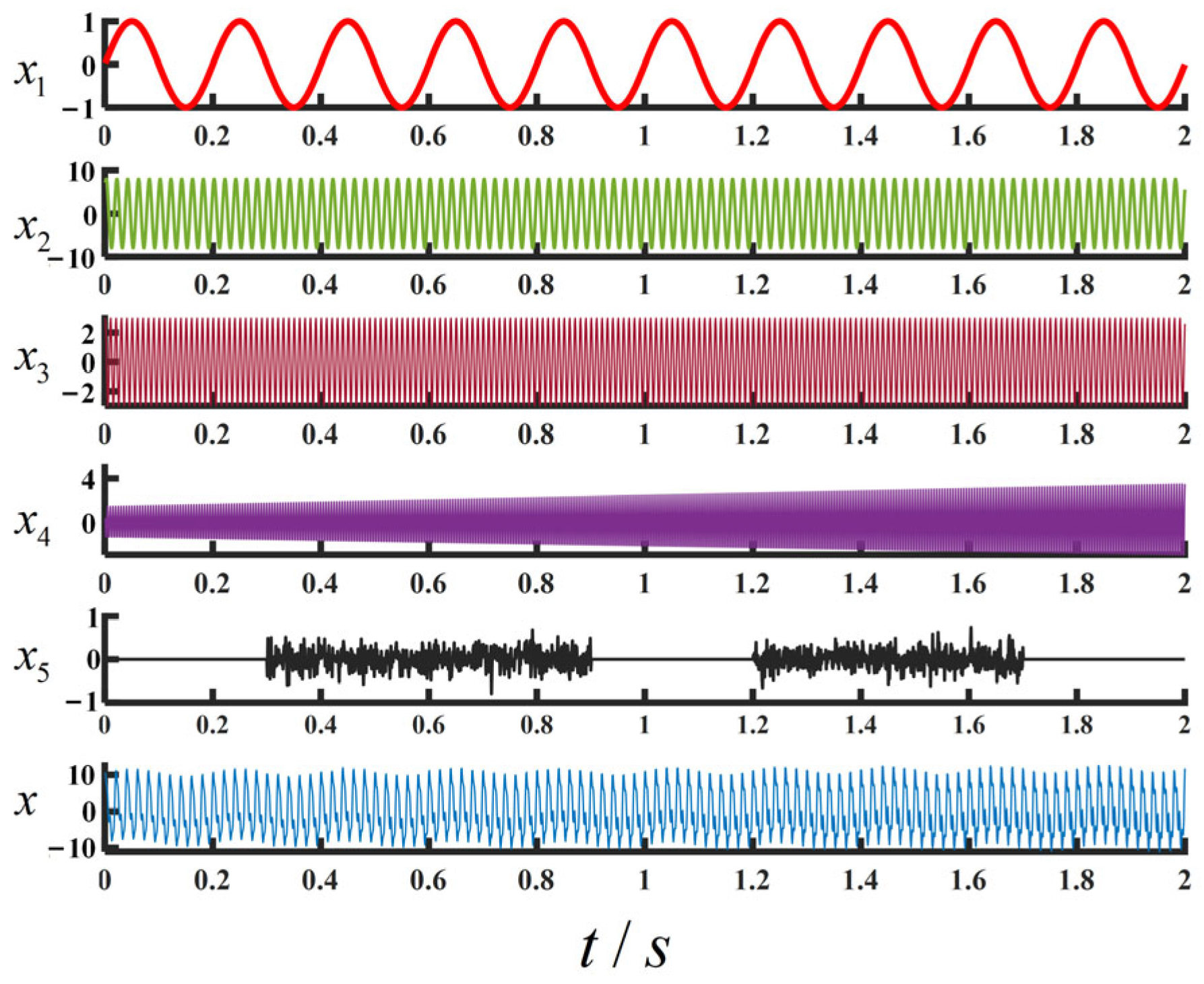
To illustrate the advantages of improved EWT decomposition and reconstruction, simulation experiments were carried out and are reported in this section. The original signal x consists of x1, x2, x3, x4, and x5, with a sampling frequency of 1000 Hz and a sampling time of 2 s. The signal is shown in Figure 2.
x 1 = sin ( 10 π t ) x 2 = 8 sin ( 100 π t + π / 4 ) x 3 = 3 sin ( 200 π t + π / 3 ) x 4 = ( t + 1.5 ) sin ( 400 π t + π / 2 ) x 5 = [ z e r o ( 1 , 300 ) , 0.2 · r a n d n ( 1 , 600 ) , z e r o ( 1 , 300 ) , 0.2 · r a n d n ( 1 , 500 ) , z e r o ( 1 , 300 ) ] x = x 1 + x 2 + x 3 + x 4 + x 5
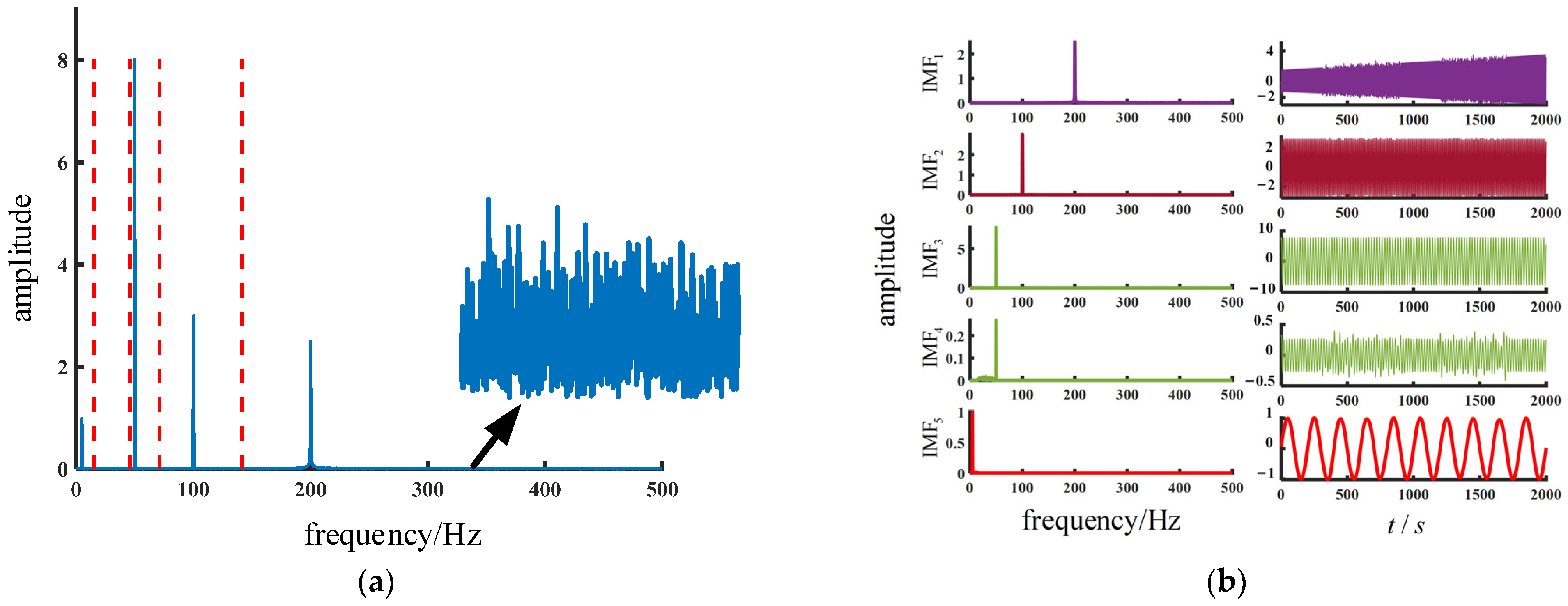
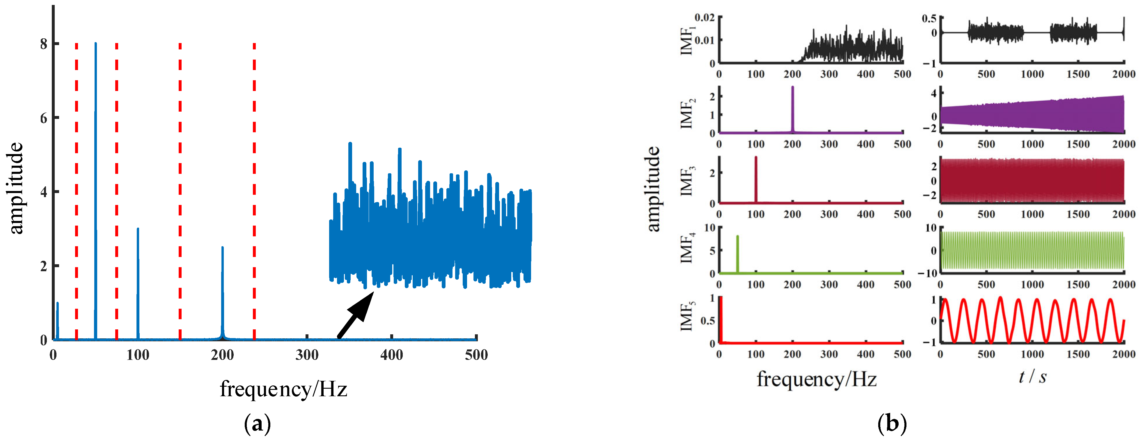
The band division and decomposition results of the classical EWT algorithm for the original signal x are shown in Figure 3. The band division and decomposition results of the improved EWT algorithm for the original signal x are shown in Figure 4. The different colorful lines represent different frequencies of the signal decomposition.
As shown in Figure 3, the classical EWT algorithm decomposition yields a large amount of noise mixed between IMF1 and IMF4, and there is modal confusion in IMF3 and IMF4. As shown in Figure 4, the improved EWT algorithm shows no modal confusion, while the noise is decomposed separately (IMF1), and each modal decomposition contains almost no noise.
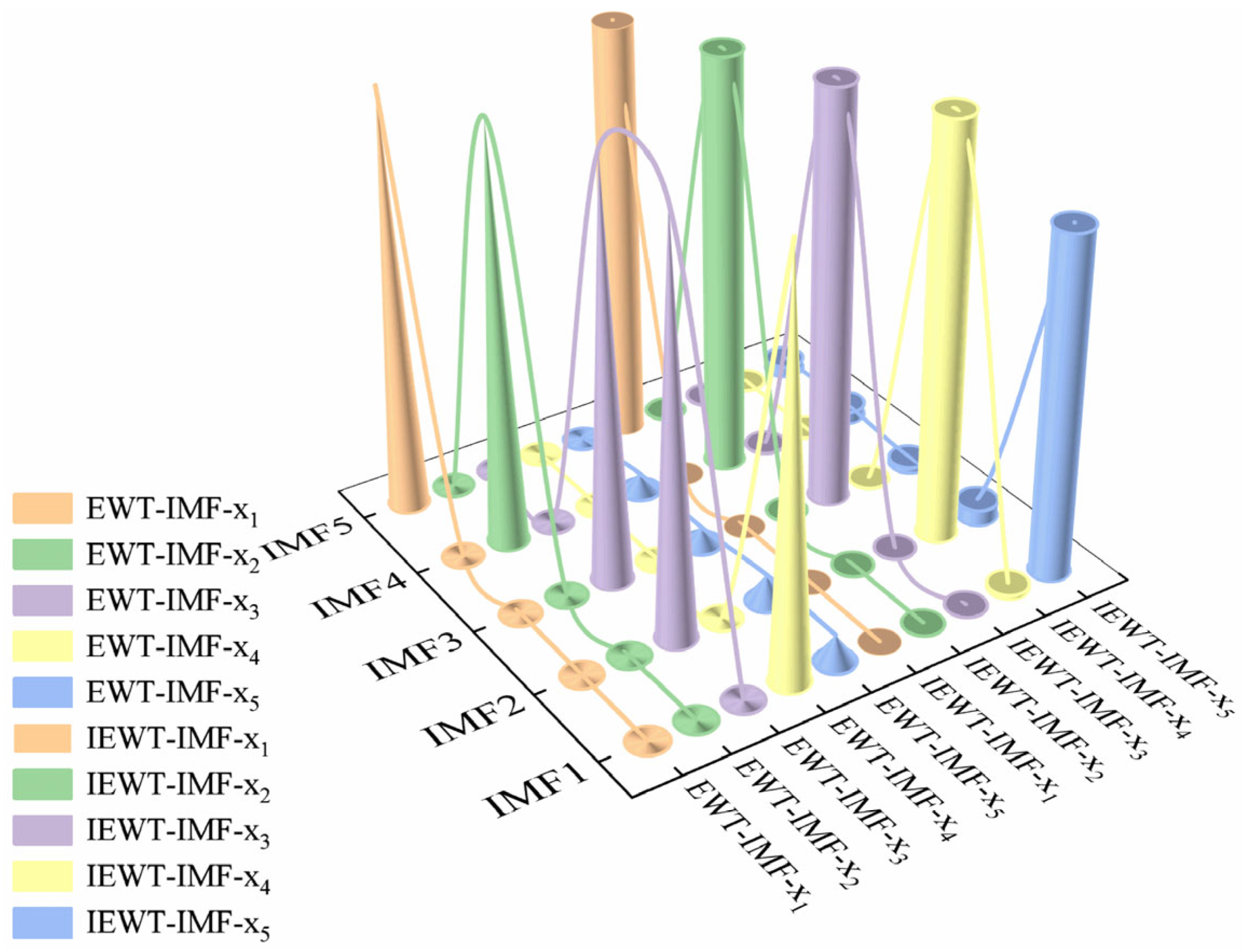
In order to evaluate the modal components of the two decompositions, the concept of correlation coefficients is introduced. The correlation coefficient can be used to analyze the degree of correlation between two signals, with a correlation coefficient greater than 0.8 indicating that the two signals are highly correlated [20]. The results of the correlation coefficient analysis for the two decompositions are shown in Figure 5. The cones represent the correlation coefficients between the component IMFs after decomposition by the classical EWT algorithm, and the cylinders represent the correlation coefficients between the component IMFs after decomposition by the improved EWT algorithm. This Figure shows that the classical EWT algorithm shows the phenomenon of modal confusion and does not decompose the noisy signal. In contrast, the improved EWT algorithm effectively separates the noisy component while avoiding modal confusion.
The Hilbert–Huang transform is a standard method for analyzing the frequency characteristics of signals [21], and Figure 6 reflects the Hilbert–Huang mapping of the two decomposition methods. The different colorful lines indicate different frequencies on the Hilber–Huang spectrum, and the dots indicate the frequencies of the various modal mixes and noise. Figure 6a shows that the classical EWT algorithm extracts a signal with a frequency of 200 Hz containing a large amount of noise and modal confusion at 100 Hz. As shown in Figure 6b, the improved EWT algorithm effectively extracts the individual frequency components without modal confusion.
After the signal decomposition using the improved EWT algorithm, signal reconstruction is carried out by removing the noisy signal through weighted alignment entropy. The permutation entropy and weighted permutation entropy of standard signals are shown in Table 1.
According to the entropy value of the alignment entropy, to determine whether the signal is noise, a reference threshold b needs to be given; when the entropy value exceeds the reference threshold b, it is a noisy signal. Paper [22] showed through several experiments that taking b as 0.55~0.6 means that the effect is optimal, this paper takes b = 0.6. From Table 1, it can be seen that alignment entropy cannot correctly determine the intermittent signal, this is due to the fact that the intermittent signal shows a mutation phenomenon, and the alignment entropy is not sensitive to this phenomenon. In summary, noisy signals can be detected by weighting the alignment entropy. The noise signal is filtered out and the reconstructed signal is obtained, and its time–frequency curve is shown in Figure 7.

3. Graphical Neural Networks

3.1. Diagrammatic Composition of the Distribution Network

Distribution networks are mostly radial and have a natural graph structure that can be abstracted as an undirected graph consisting of vertices and edges. Figure 8 represents a simple distribution network topology graph structure. The graph nodes from 1 to 7represent the electrical nodes of the distribution network, and the graph’s edges represent the lines of the distribution network.
For ease of description, the adjacency matrix E is used to describe the connectivity of vertices and edges in the graph as the characteristic input for the edges of the distribution network, where 0 means that the nodes are not connected, 1 means that they are connected, ERN×N, and N is the number of vertices. The distribution network graph structure shown in Figure 8 has seven nodes and six edges, and its adjacency matrix can be expressed as
E = 0 1 0 0 0 0 0 1 0 1 0 1 0 0 0 1 0 1 0 1 0 0 0 1 0 0 0 0 0 1 0 0 0 0 0 0 0 1 0 0 0 1 0 0 0 0 0 1 0
Each node’s input is the denoised zero-sequence current signal, and the input vectors of each node are stitched together to obtain a matrix X = {x1, x2, …, xn}, where n is the number of nodes, and the matrix X is used as the input of the node characteristics of the distribution network as a whole. The graph structure of different sections when a fault occurs is labeled with different labels as a basis for classification.

3.2. Graph Neural Network (GNN)

GNNs are continuously proposed, mainly using neighborhood aggregation and graph-level pooling. These GNN models are not effective in graph classification because the design of GNNs is mainly based on empirical intuition, heuristics, and experimental trial and error. Hence, there is currently less theoretical understanding of the properties and limitations of GNNs and limited formal analysis of GNN representational capabilities.
For a graph, G = (V, E), where V and E denote nodes and edges of the graph, respectively, vV denotes a node v in graph G, and eE denotes an edge e in graph G. In the set of edges E, an edge (u, v) connects a pair of nodes u and v. The neighborhood of a node, v, can also be defined as N(v) = {uV|(v, u) ∈ E}.
(1) Aggregating neighborhood information.
a v ( k ) = AGGREGATE ( k ) ( { h u ( k 1 ) : u N ( v ) } )
where av(k) is the representation vector of its neighborhood information generated by node v at the kth iteration, obtained by aggregating the representation vectors of its neighboring nodes; hu(k−1) denotes the representation vector of node u at the k-1st iteration.
(2) Updating node information.
h v k = COMBINE ( k ) ( h v ( k 1 ) , a v ( k ) )
where hvk denotes the representation vector of node v after the kth iteration, which is generated by combining the representation vector of node v at the k-1st iteration with the representation vector of the neighborhood information of node v at the kth iteration.
(3) Reading out graph information.
For the graph classification task, a representation vector of the graph needs to be learned to represent the spatial topology of the graph and the information features of the nodes. This feature vector is then sent to the classifier for classification.
h G = READOUT ( { h v ( k ) | v G } )
where hG is the representation vector of the graph, and the READOUT module is used to aggregate the features of the nodes, which can be either a simple alignment invariant function or a complex graph-level pooling function.

3.3. Graphical Isomorphic Network (GIN)

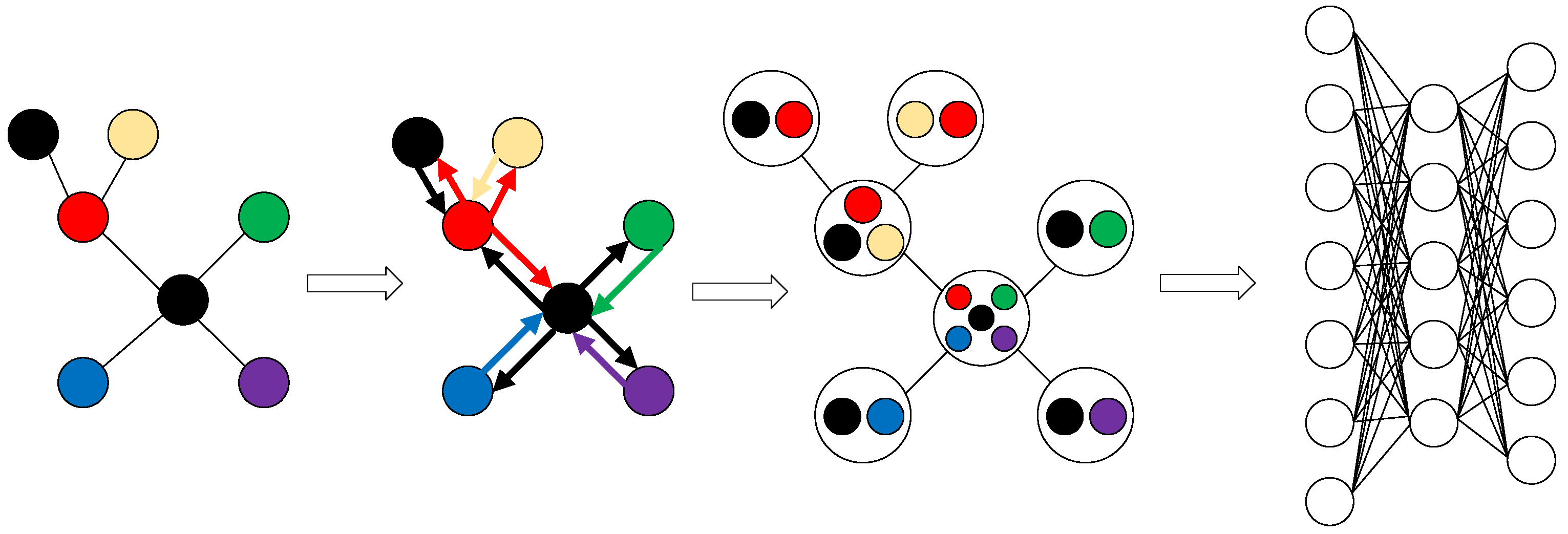
The graph isomorphic network (GIN) model has the best expressiveness among GNNs that follow the neighborhood aggregation scheme [23]. The GIN learning graph vector representation process is shown in Figure 9. Different colorful circles represent different nodes, and arrows represent the direction of aggregation. The process consists of three phases: the AGGREGATE phase passes information from the node itself, the COMBINE phase accepts information from neighboring nodes, and the READOUT phase integrates the complete graph vector.
The COMBINE module is defined as
h v ( k ) = MLP ( k ) ( 1 + ε ( k ) ) h v ( k 1 ) + u N ( v ) h u ( k 1 )
where MLP (multiple-layer perception) is a multi-layer perception machine that can approximately fit any function and ε is a learnable parameter. The READOUT module uses CONCAT and SUM pooling to sum the nodes of each iteration to obtain the features of the graph, which are finally stitched together. The final representation vector of the graph is
h G = CONCAT ( SUMPool ( { h v ( k ) | v G } ) | k = 0 , 1 , K )
The overall structure of the GIN model used in this article is shown in Figure 10. The model consists of three GIN layers, one SUMPool layer, one Relu activation function, one Dropout layer, and one fully connected layer. Each GIN layer consists of a linear transformation layer, a BatchNorm layer, a Relu activation function, and a linear transformation layer. The loss function is log_softmax.

4. Experimental Verification and Analysis

4.1. Fault Section Location Procedure

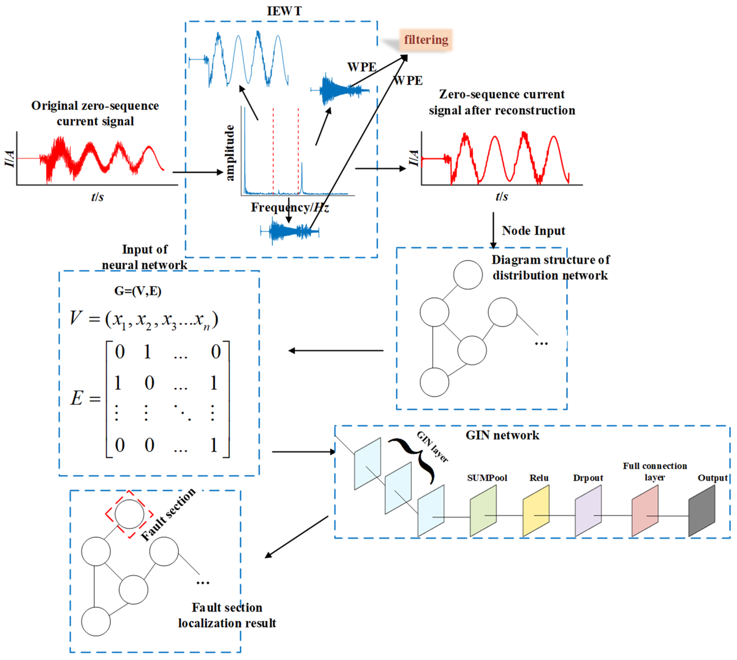
The proposed IEWT method in this paper is based on kurtosis and optimizes the EWT using the N-point search method. The improved EWT is utilized to decompose the electrical signal into multiple modal components, and the noise part of the signal is filtered out for signal reconstruction. Then, according to the topology of the distribution network, the corresponding graph is constructed as the input of the GIN. The denoised zero-sequence current signal is used as the node input of the GIN. The features of the graphs are mined autonomously by the GIN to achieve fault section location in distribution networks. The fault section location process is shown in Figure 11.
Step 1: Perform IEWT decomposition and denoising on the zero-sequence current signal to obtain the denoised reconstructed zero-sequence current signal.
Step 2: Construct the graph structure G = (V, E) of the distribution network, where V represents the node inputs, V = (x1, x2, x3, …, xn), and in xi, i = 1, 2, 3, …, n represents the denoised zero-sequence current signal corresponding to each node. E represents the edge inputs, which are the adjacency matrix of the distribution network. Meanwhile, label the graph structures generated from different fault intervals accordingly.
Step 3: Input the constructed graphs into the GIN for training, obtain the model file, and use this file to complete single-phase ground fault section location in the distribution network.

4.2. Simulation Environment

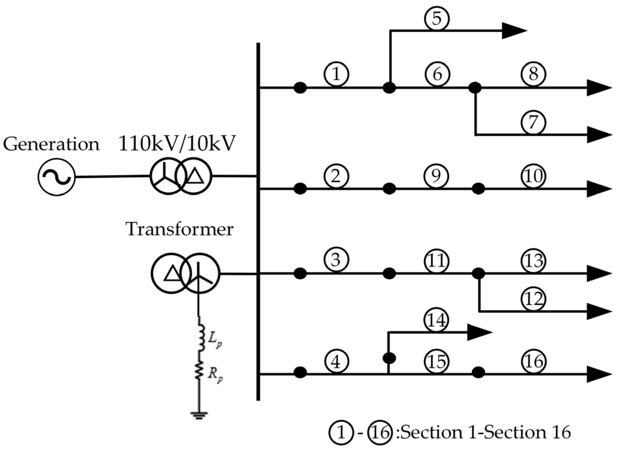
We built a 110 kV/10 kV distribution network model based on MATLAB R2022b/Simulink, the topology of which is shown in Figure 12. The network comprises 16 sections; sections 1 to 4 are overhead lines, and sections 5 to 16 are cable lines. The lengths of the lines are as follows: L1 = 3 km, L2 = 2 km, L3 = 1 km, L4 = 2 km, L5 = 4 km, L6 = 3 km, L7 = 0.5 km, L8 = 3 km, L9 = 3 km, L10 = 3 km, L11 = 3 km, L12 = 3 km, L13 = 3 km, L14 = 3 km, L15 = 3 km, and L16 = 1 km. The line parameters are shown in Table 2. The terminal loads of the lines are all set to 0.6 + 0.3 MV·A. Arc suppression coils are used in overcompensation mode, with overcompensation set at 10%.

4.3. Data Acquisition and Neural Network Input

To simulate the operational conditions of the distribution network under actual circumstances, the following parameters are set: fault section, fault phase, fault initial phase angle, fault grounding resistance, and fault distance.
The fault section is selected sequentially from Section 1 to Section 16. The fault phase is chosen among phases A, B, and C. The fault initial phase angles are set as 0°, 30°, 60°, 90°, 120°, and 150°, respectively. The grounding resistance starts from 0 Ω and increases from 50 Ω to 300 Ω. Then, it increases at a rate of 100 Ω up to 1500 Ω. The fault distance starts from the beginning of the line and increases at a rate of 0.5 km up to the end of the line.
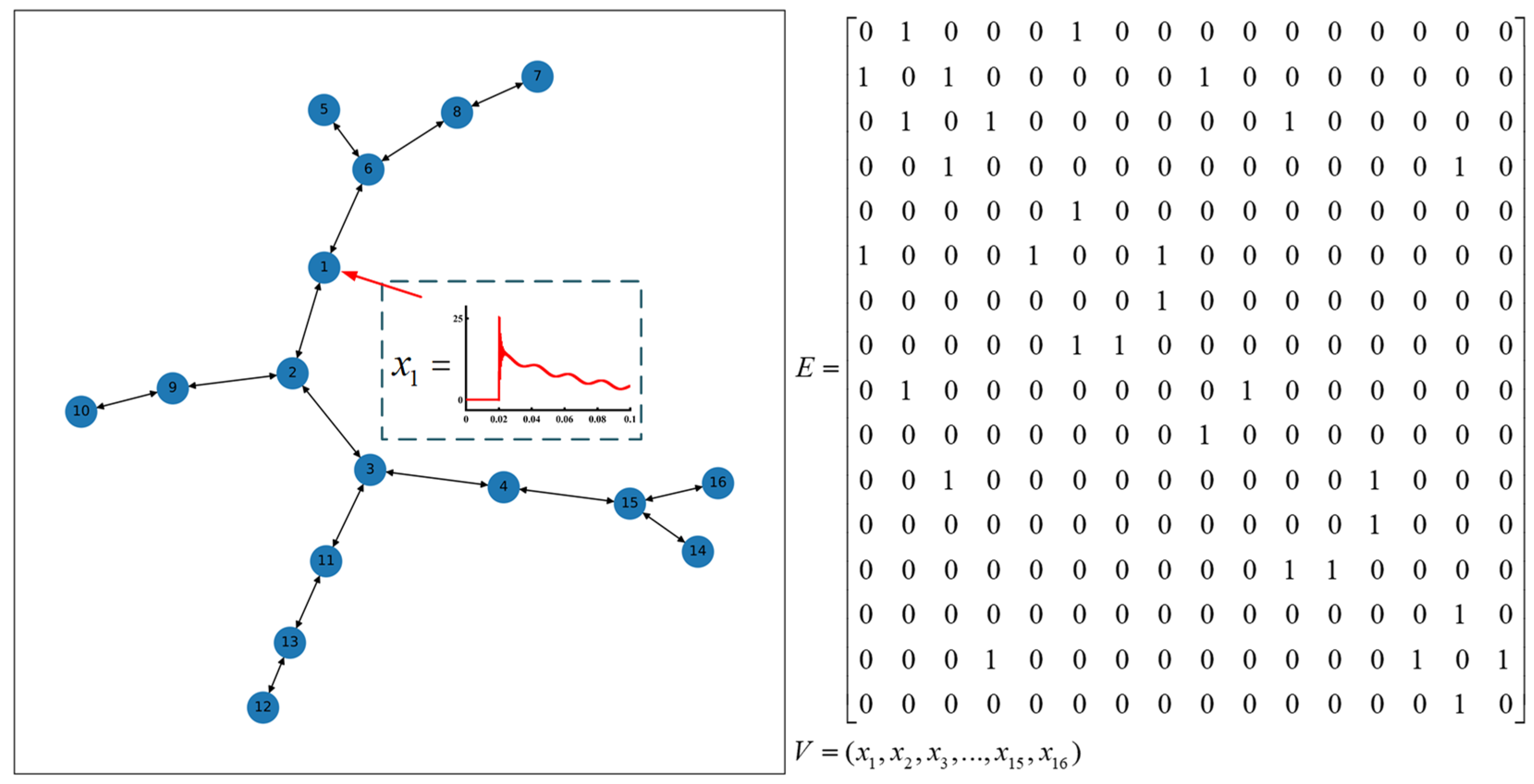
The data acquisition frequency is 12.8 kHz, and the system operation time is 0.2 s. The zero-sequence current signals of the pre-fault period and the two post-fault periods are collected for each node. Following the fault section localization process described above, a distribution network characteristic map is generated, as shown in Figure 13, with corresponding labels based on the different fault sections. The numbers left indicate different fault sections from Section 1 to Section 16. A total of 26,244 fault characteristic maps, under single-phase grounding conditions in the distribution network, are generated.
Based on the proportion of characteristic maps in each section, a training set and a test set are generated. The training set accounts for 80% of the total, with 20,995 maps, while the test set accounts for 20%, totaling 5248 maps. To validate the robustness of the training results, three sets of 2000 maps, each with different fault parameters, are randomly generated as a validation set.

4.4. Verification and Analysis of Fault Section Localization Results

After training the model for 100 epochs, both the training accuracy and loss function stabilized, indicating the convergence of the model. With the number of training epochs set to 150, the results are shown in Figure 14. From this Figure, it can be observed that with the increase in epochs, the loss functions of both the training and test sets continuously decrease, while the accuracy steadily improves. Moreover, as the training set’s loss function decreases, the test set’s loss rate decreases, indicating that the model has yet to experience overfitting. The final accuracy of the model stabilizes at 99.95%.
Three sets of randomly generated validation data were utilized to validate the model’s generalization ability, each containing 2000 distribution network fault characteristic maps. In the first validation set, fourteen misclassifications occurred; in the second validation set, nine misclassifications occurred; and in the third validation set, six misclassifications occurred. The recognition accuracies were 99.3%, 99.55%, and 99.7%, respectively. This indicates that the model possesses strong generalization capabilities.
The experimental results demonstrate that the method performs well with different fault types, initial phase angles, grounding resistances, and fault distances. Additionally, it exhibits strong generalization across different scenarios.

4.5. Comparative Verification

4.5.1. Comparative Validation of Different Neural Networks

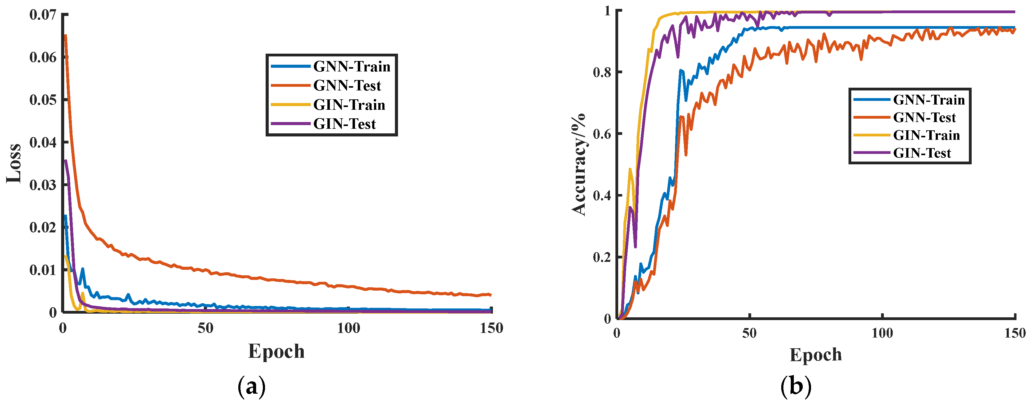
In order to validate the superiority of GINs over traditional GNNs in graph classification tasks, we conducted model training using both a GNN and a GIN. The training results are depicted in Figure 15. It can be observed that compared to the GNN, training with the GIN resulted in lower loss function, higher accuracy, and faster convergence speed. When trained using GNN, the highest model accuracy achieved was 90.85%, whereas with GIN training, the highest accuracy reached 99.95%. This indicates that compared to GNNs, GINs possess more robust graph representation capabilities and perform better in graph classification tasks.

4.5.2. Noise Immunity Verification

In real-world scenarios, the original zero-sequence current signals collected from the distribution network contain considerable noise. To validate the robustness of the proposed method, three different approaches were employed:
Method 1: The original zero-sequence current signals were directly used as node inputs for the distribution network characteristic maps.
Method 2: The original zero-sequence current signals were decomposed and reconstructed using EWT (empirical wavelet transform) and then used as node inputs for the distribution network characteristic maps.
Method 3: The original zero-sequence current signals were decomposed and reconstructed using IEWT (improved empirical wavelet transform), which is the approach proposed in this paper.
The distribution network characteristic maps obtained using the three methods were trained and tested using GINs, and the results are presented in Table 3. It can be observed that after undergoing IEWT decomposition and reconstruction, the accuracy of fault section localization was significantly improved.
Adding noise with signal-to-noise ratios (SNRs) of 30 dB, 25 dB, 20 dB, and 15 dB to the original signal, a comparison is made between the proposed method in this paper and the methods proposed in references [10,13]. The results are shown in Table 4. As the noise level increases, the proposed method in this paper maintains relatively high accuracy in fault section localization, indicating its robustness against noise.

4.5.3. High-Resistance Grounding Comparative Validation

When a high-resistance grounding fault occurs, the fault signal characteristics are not distinct, affecting fault section localization accuracy. The method proposed in this paper involves the denoising and reconstruction of the original fault signal, the amplification of features, and thorough feature extraction through neural networks. This approach maintains a high accuracy in fault section localization even under high-resistance grounding conditions. By comparing our method with those proposed in references [1,2], with grounding resistances set to 1000 Ω and 1500 Ω, respectively, the experimental results are shown in Table 5. From Table 5, it can be observed that the methods proposed in references [1,2] both exhibit misclassifications under high-resistance grounding conditions, while our method continues to identify the fault section correctly.

4.5.4. Validation of Distribution Networks with Distributed Energy Resources

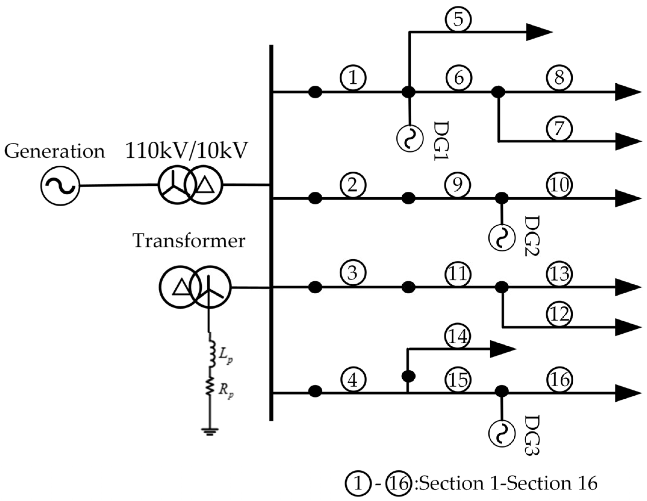
With the development of distributed energy resource (DER) technology, fault section localization in distribution networks containing distributed energy resources has received widespread attention. Incorporating distributed energy resources further increases the difficulty of fault section localization in distribution networks. In order to verify the fault section localization capability of the proposed method in distribution networks containing distributed energy resources, the following simulation experiments were conducted.
Three distributed energy resources are integrated into the simulated distribution network topology. The topology of the distribution network after their integration is shown in Figure 16. Without retraining the model, the proposed method and methods proposed in references [1,2] are used for validation. The validation results are presented in Table 6. It can be observed that under the condition of distributed energy resource integration, the proposed method maintains a high accuracy in fault section localization.

4.5.5. Dynamic Mold Experiment

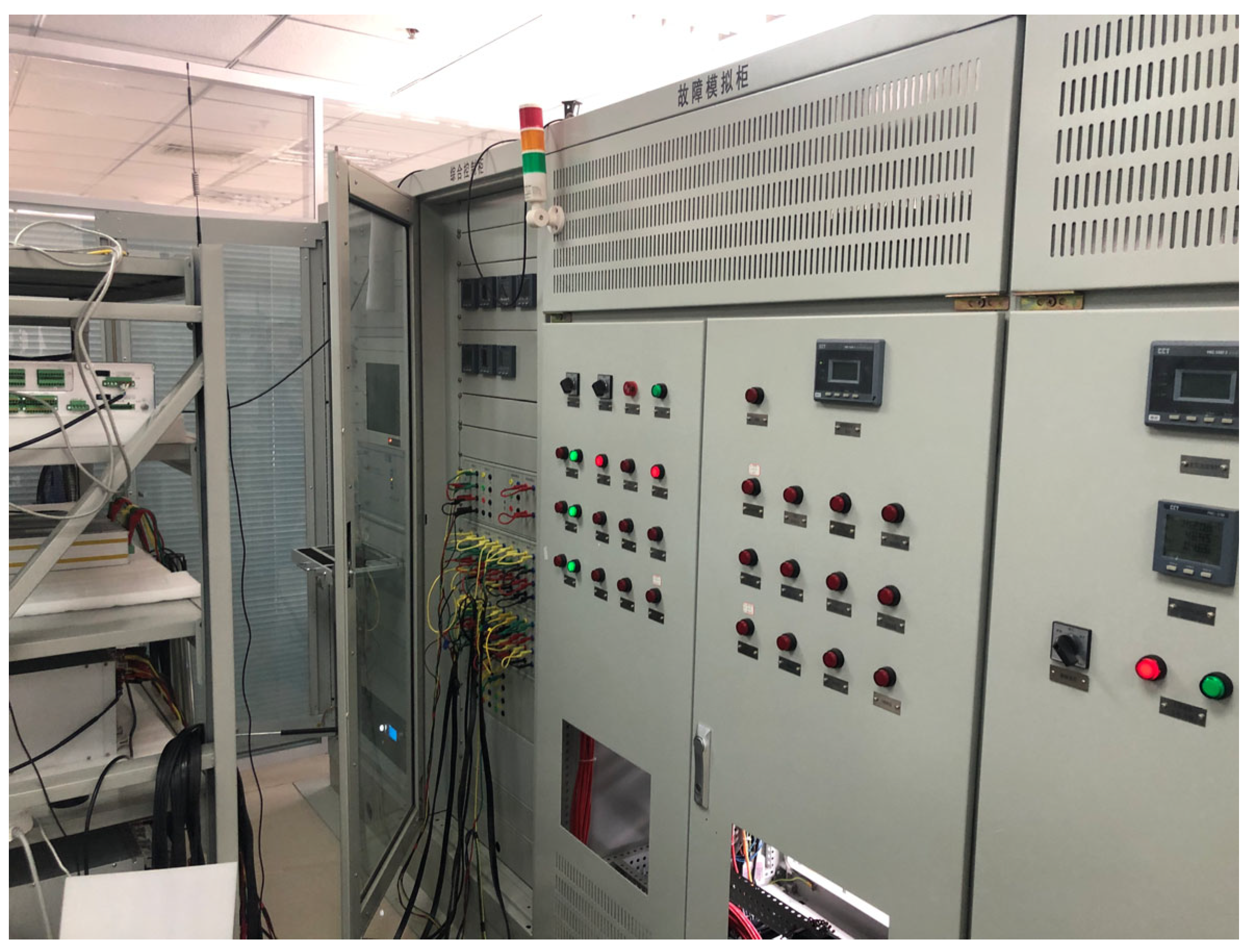
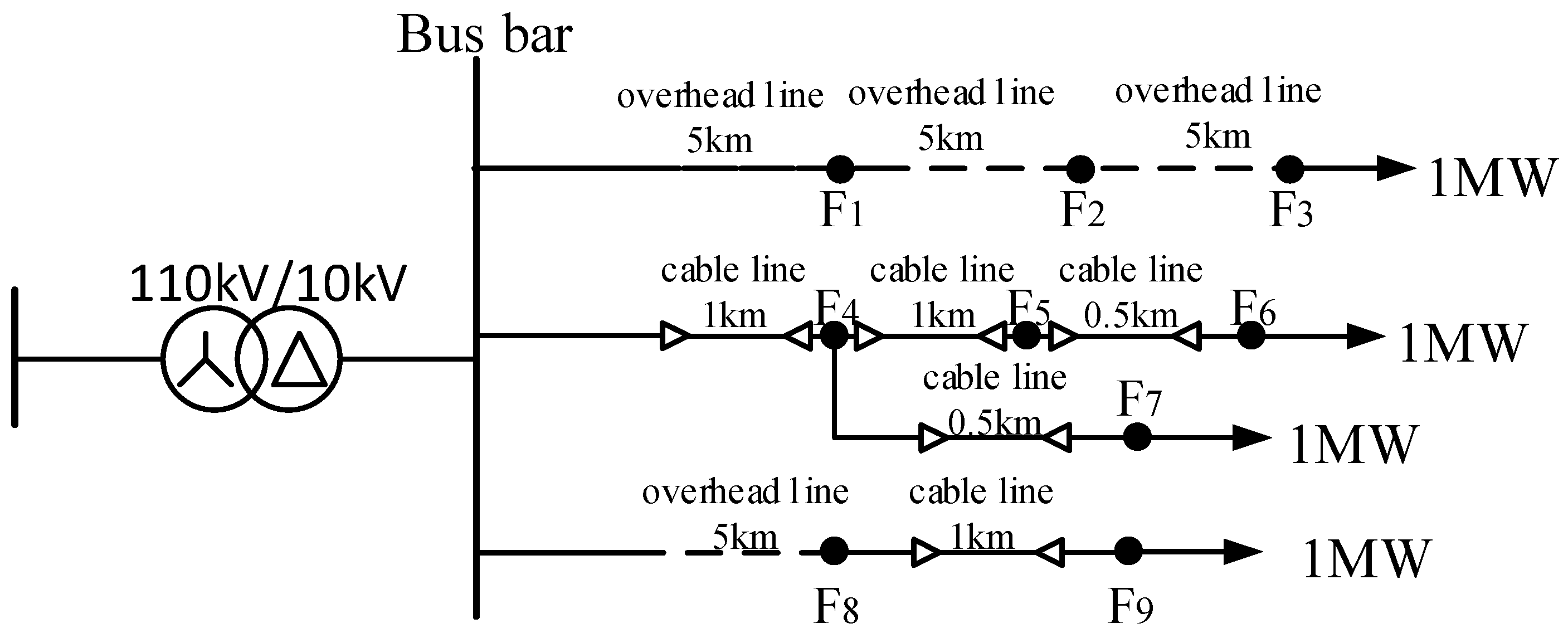
A modal simulation fault diagnosis experimental platform was employed to validate the effectiveness of the proposed method in practical applications. The multi-mode laboratory is depicted in Figure 17. Utilizing MATLAB R2022b/Simulink, a simulation model identical to the dynamic simulation fault diagnosis platform was constructed, as shown in Figure 18.
Data collection and model training were conducted using the simulation model. The model’s reliability was verified using data from the dynamic simulation fault diagnosis experimental platform. The test results are presented in Table 7. From Table 7, it can be observed that the proposed method accurately locates the fault section, confirming the practicality of the proposed method in real-world scenarios.

5. Conclusions

This study proposed a novel method for fault section localization in distribution networks using an improved EWT and GIN. The research findings are as follows:
An improved signal-denoising algorithm based on IEWT and WPE was proposed. Simulation results demonstrated that compared to existing algorithms, the improved EWT algorithm offers more reasonable frequency band division, effectively decomposing noise signals while suppressing mode confusion. The utilization of WPE accurately identifies abrupt noise signals. Overall, the improved EWT algorithm exhibits a better denoising performance.
A distribution network characteristic map was constructed to consolidate fault features onto a single map, transforming fault section localization into a graph classification task. The GIN autonomously explores the features of the distribution network graph, fully exploiting fault characteristics.
The experimental results indicate that this approach is unaffected by fault types, initial phase angles, fault grounding resistance, and neutral point grounding methods compared to traditional fault section localization methods. It performs well under distributed energy resource integration scenarios and real-world conditions.
In conclusion, the proposed method demonstrates strong noise resistance and stability, accurately identifying fault sections with a localization accuracy of up to 99.95%. This research provides a new perspective on fault section localization in distribution networks.

Author Contributions

Conceptualization, C.W., L.F., S.H., G.R. and W.W.; methodology, S.H.; software, W.W.; validation, S.H., W.W. and L.F.; formal analysis, S.H.; investigation, W.W.; resources, S.H., W.W. and C.W.; data curation, W.W.; writing—original draft preparation, S.H., W.W. and G.R.; writing—review and editing, W.W.; visualization, S.H., W.W. and C.W.; supervision, S.H.; project administration, S.H. All authors have read and agreed to the published version of the manuscript.

Funding

This work was supported by State Grid Shanxi Electric Power Company through “Research on fault type identification and localization technology of distribution network based on multi-dimensional features”, grant number 5205M0230008.

Data Availability Statement

The data presented in this study are available on request from the corresponding author.

Conflicts of Interest

Authors Chen Wang, Lijun Feng, Guohui Ren were employed by State Grid Yuncheng Power Supply Company. The remaining authors declare that the research was conducted in the absence of any commercial or financial relationships that could be construed as a potential conflict of interest.

Nomenclature

EWTempirical wavelet transform
IEWTimproved empirical wavelet transform
IMFsintrinsic mode functions
PEpermutation entropy
WPEweighted permutation entropy
GNNgraph neural network
GINgraphical isomorphic network

References

  1. Liang, J.; Jing, T.; Niu, H.; Wang, J. Two-terminal Fault Location Method of Distribution Network Based on Adaptive Convolution Neural Network. IEEE Access 2020, 8, 54035–54043. [Google Scholar] [CrossRef]
  2. Cheng, H.-J.; Meng, H.; Jiang, P.-J. Research on Fault Line Selection in Small-current Neutral Grounding Power System. In Proceedings of the 2013 IEEE International Conference on Vehicular Electronics and Safety, Dongguan, China, 28–30 July 2013; pp. 206–209. [Google Scholar] [CrossRef]
  3. Mirshekali, H.; Dashti, R.; Handrup, K.; Shaker, H.R. Real Fault Location in a Distribution Network Using Smart Feeder Meter Data. Energies 2021, 14, 3242. [Google Scholar] [CrossRef]
  4. Larik, N.A.; Li, M.S.; Wu, Q.H. Enhanced Fault Detection and Localization Strategy for High-Speed Protection in Medium-Voltage DC Distribution Networks Using Extended Kalman Filtering Algorithm. IEEE Access 2024, 12, 30329–30344. [Google Scholar] [CrossRef]
  5. Hamza, W.; Ali, B.S.B.; Abdul, W.; Hani, A.; Khalid, M.K. Fault Identification, Classification, and Localization in Microgrids Using Superimposed Components and Wigner Distribution Function. Front. Energy Res. 2024, 12, 1379475. [Google Scholar] [CrossRef]
  6. Kumar, A.; Bhalja, B.R.; Kumbhar, G.B. Novel Technique for Location Identification and Estimation of Extent of Turn-to-Turn Fault in Transformer Winding. IEEE T. Ind. Electron. 2023, 70, 7382–7392. [Google Scholar] [CrossRef]
  7. Xu, S.; Ouyang, J.; Chen, J.; Xiong, X. A Section Location Method of Single-Phase Short-Circuit Faults for Distribution Networks Containing Distributed Generators Based on Fusion Fault Confidence of Short-Circuit Current Vectors. Electronics 2024, 13, 1741. [Google Scholar] [CrossRef]
  8. Jiang, Z.; Zeng, X.; Liu, F.; Yu, K.; Bi, L.; Wang, Y. Active Fault-Locating Scheme for Hybrid Distribution Line Based on Mutation of Aerial-Mode Injected Pulse. Energies 2024, 17, 2248. [Google Scholar] [CrossRef]
  9. Sun, G.; Ma, W.; Wei, S.; Cai, D.; Wang, W.; Xu, C.; Zhang, K.; Wang, Y. A Fault Location Method for Medium Voltage Distribution Network Based on Ground Fault Transfer Device. Electronics 2023, 12, 4790. [Google Scholar] [CrossRef]
  10. Rezapour, H.; Jamali, S.; Bahmanyar, A. Review on Artificial Intelligence-Based Fault Location Methods in Power Distribution Networks. Energies 2023, 16, 4636. [Google Scholar] [CrossRef]
  11. Lin, W.-C.; Huang, W.-T.; Yao, K.-C.; Chen, H.-T.; Ma, C.-C. Fault Location and Restoration of Microgrids via Particle Swarm Optimization. Appl. Sci. 2021, 11, 7036. [Google Scholar] [CrossRef]
  12. Shafiullah, M.; Abido, M.A.; Abdel-Fattah, T. Distribution Grids Fault Location Employing ST based Optimized Machine Learning Approach. Energies 2018, 11, 2328. [Google Scholar] [CrossRef]
  13. Bukhari, S.B.A.; Kim, C.-H.; Mehmood, K.K.; Haider, R.; Saeed Uz Zaman, M. Convolutional Neural Network Based Intelligent Protection Strategy for Microgrids. IET Gener. Transm. Distrib. 2020, 14, 1177–1185. [Google Scholar] [CrossRef]
  14. Gao, J.; Guo, M.; Lin, S.; Chen, D. Advancing High Impedance Fault Localization Via Adaptive Transient Process Calibration and Multiscale Correlation Analysis in Active Distribution Networks. Measurement 2024, 229, 114431. [Google Scholar] [CrossRef]
  15. Kim, M.-S.; An, J.-G.; Oh, Y.-S.; Lim, S.-I.; Kwak, D.-H.; Song, J.-U. A Method for Fault Section Identification of Distribution Networks Based on Validation of Fault Indicators Using Artificial Neural Network. Energies 2023, 16, 5397. [Google Scholar] [CrossRef]
  16. Mirshekali, H.; Dashti, R.; Keshavarz, A.; Shaker, H.R. Machine Learning-Based Fault Location for Smart Distribution Networks Equipped with Micro-PMU. Sensors 2022, 22, 945. [Google Scholar] [CrossRef]
  17. Li, J.; Wang, X.; He, J.; Zhang, Y.; Zhang, D. Distribution Network Fault Location Method Based on Graph Attention Network. Power Grid Technol. 2021, 45, 2113–2121. [Google Scholar] [CrossRef]
  18. Gilles, J. Empirical Wavelet Transform. IEEE Trans. Signal Proces. 2013, 61, 3999–4010. [Google Scholar] [CrossRef]
  19. Feng, X.; Chen, Z.; Li, J.; Cai, J.; Liang, J. Electromagnetic Time Kurtosis for Time-Reversal Source Reconstruction with Band-Limited Signals. In Proceedings of the 2022 IEEE/MTT-S International Microwave Symposium—IMS 2022, Denver, CO, USA, 19–24 June 2022; pp. 12–15. [Google Scholar]
  20. Wang, X.; Gao, J.; Song, G.; Cheng, Q.; Wei, X.; Wei, Y. Faulty Line Selection Method for Distribution Network Based on Variable Scale Bistable System. J. Sens. 2016, 2016, 7436841. [Google Scholar] [CrossRef]
  21. Wang, Z.; Qiao, P.; Shi, B. Nonpenetrating Damage Identification Using Hybrid Lamb Wave Modes from Hilbert-Huang Spectrum in Thin-walled Structures. Shock Vib. 2017, 2017, 5164594. [Google Scholar] [CrossRef]
  22. Zheng, J.; Liu, T.; Meng, R.; Liu, Q. Generalized Composite Multiscale Permutation Entropy and PCA Based Fault Diagnosis of Rolling Bearings. J. Vib. Shock 2018, 37, 61–66. [Google Scholar]
  23. Xu, K.; Hu, W.; Leskovec, J.; Jegelka, S. How Powerful are Graph Neural Networks? arXiv 2018, arXiv:1810.00826. [Google Scholar]
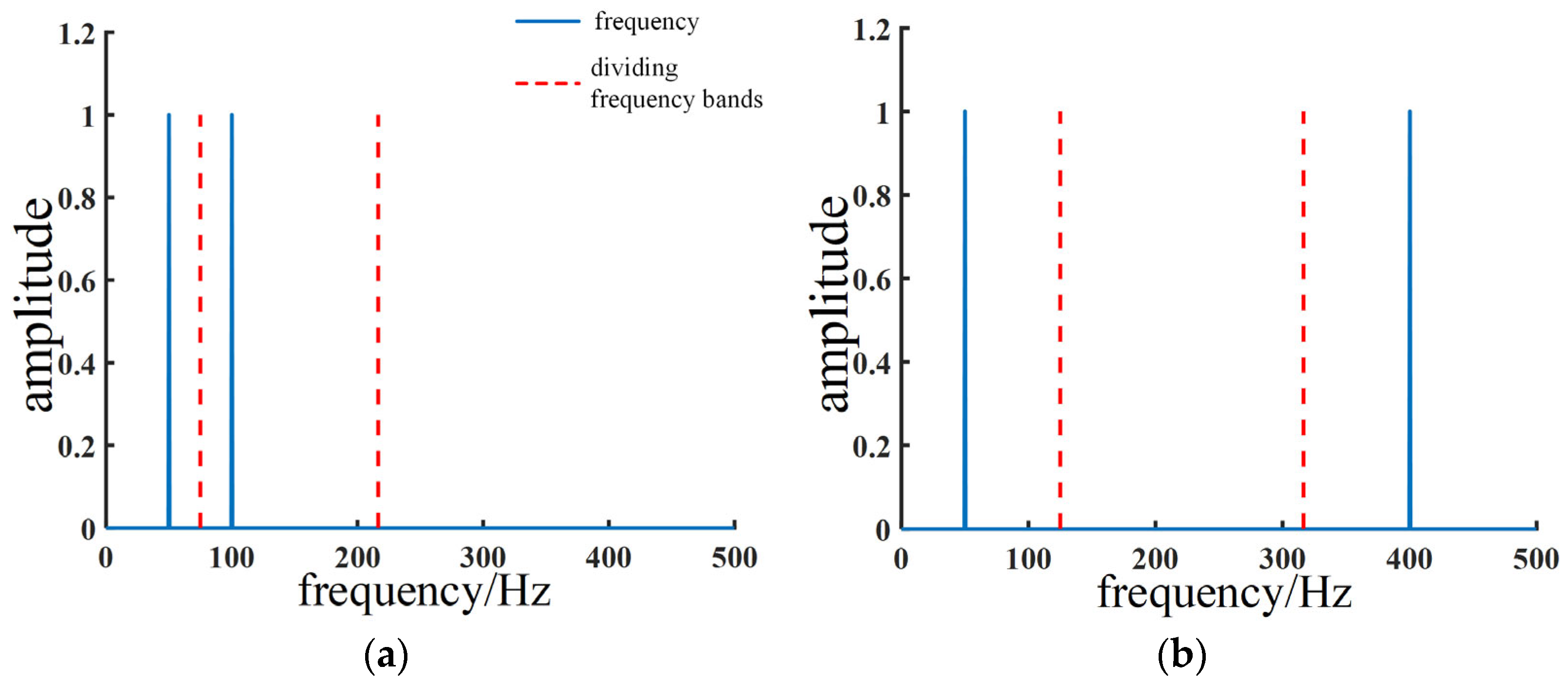
Figure 1. Schematic diagram of the improved EWT banding: (a) band N division, (b) intermediate band division.
Information 15 00650 g001
Figure 2. Original signal.
Information 15 00650 g002
Figure 3. Classical EWT algorithm: (a) classical EWT algorithm banding results, (b) classical EWT signal decomposition results.
Information 15 00650 g003
Figure 4. IEWT algorithm: (a) IEWT banding results, (b) IEWT signal decomposition results.
Information 15 00650 g004
Figure 5. Correlation coefficients of the original simulation signal decomposition results of the two methods.
Information 15 00650 g005
Figure 6. Hilbert–Huang yellow spectrum analysis by different methods: (a) Hilbert–Huang spectrum analysis of the classical EWT algorithm, (b) Hilbert–Huang spectrum analysis of the improved EWT algorithm.
Information 15 00650 g006
Figure 7. Time–frequency curve of the reconstructed signal.
Information 15 00650 g007
Figure 8. Diagram structure of a simple distribution network.
Information 15 00650 g008
Figure 9. GIN learns the graph vector process.
Information 15 00650 g009
Figure 10. GIN structure.
Information 15 00650 g010
Figure 11. Fault section location procedure.
Information 15 00650 g011
Figure 12. The schematic diagram of the distribution network topology.
Information 15 00650 g012
Figure 13. Structure of the distribution network characteristic map.
Information 15 00650 g013
Figure 14. Training results: (a) loss function, (b) accuracy.
Information 15 00650 g014
Figure 15. Comparative validation of different neural networks: (a) loss function, (b) accuracy.
Information 15 00650 g015
Figure 16. Distribution network with distributed generators.
Information 15 00650 g016
Figure 17. Dynamic simulation fault diagnosis experimental platform.
Information 15 00650 g017
Figure 18. Experimental model of the dynamic fault simulation system.
Information 15 00650 g018
Table 1. Permutation entropy and weighted permutation entropy of each signal.
SignalPermutation
Entropy
Weighted
Permutation Entropy
White noise0.97120.9590
Gaussian white noise0.96820.9622
High-frequency sinusoidal signal0.43380.3828
Fundamental frequency sinusoidal signal0.11020.1054
AM signal0.39260.2458
FM signal0.24520.1722
AM/FM signa0.43110.2992
Intermittent signal0.52700.9229
Table 2. Simulation model line parameters.
Circuit TypeResistance
(Ω·km−1)
Inductance
(mH·km−1)
Grounding Capacitance
(μF·km−1)
Positive PhaseZero PhasePositive PhaseZero PhasePositive PhaseZero Phase
Overhead line0.1780.251.215.540.0150.012
Cable line0.272.70.2551.020.3390.28
Table 3. Comparison of the noise immunity of the different methods.
Fault SectionNumber of SamplesAccuracy/%
Method 1Method 2Method in This Paper
112090.1494.1899.89
212091.7294.8999.96
312090.9994.7099.94
412090.1595.1999.87
512090.4695.8999.95
612090.1594.8999.94
712090.4694.8999.89
812090.3794.6099.98
912090.8795.3099.90
1012091.1595.5699.95
1112090.5395.8999.96
1212090.1095.1899.92
1312091.9795.4199.86
1412091.3495.5699.95
1512091.2295.2899.97
1612091.9095.6599.88
Table 4. Fault section localization results with different signal-to-noise ratios.
Signal-to-Noise Ratio/dBFault SectionFault TypeFault Location Result
Paper [10]Paper [13]This Paper
353AG1133
7BG777
10CG101010
11AG121111
14BG141414
16CG161616
301AG111
6BG116
7CG777
9AG299
11BG111111
15CG41415
252AG322
5BG555
8CG178
11AG111111
13BG31313
15CG151515
202AG912
5BG115
7CG877
12AG121212
13BG131313
16CG141516
Table 5. Comparison of the experimental results for high-resistance grounding.
Grounding Resistance/ΩFault SectionFault TypeFault Location Result
Reference [1]Reference [2]This Paper
10006AG566
7BG777
10CG91010
13AG111113
14BG16414
15CG151515
15001AG211
5BG115
6CG656
7AG777
13BG31113
16CG41416
Table 6. Fault localization results after the integration of distributed energy resources.
Fault SectionNumber of SamplesAccuracy/%
Reference [1]Reference [2]This Paper
112090.4293.1899.89
212088.7492.7799.84
312088.7393.1299.78
412090.9593.5699.83
512089.1593.5999.8
612088.6693.7699.8
712088.6692.5599.87
812090.6792.4799.87
912089.4893.1399.8
1012089.2693.0999.87
1112089.8693.3499.81
1212090.2693.3699.82
1312089.0992.0599.82
1412089.0993.6599.79
1512088.3092.5399.87
1612088.0693.3299.87
Table 7. Fault localization results under the conditions of the dynamic simulation fault diagnosis experimental platform.
Fault TypeFault
Point
Transition ResistanceFault Close AngleFault
Location Result
AGF10 WF1
BGF2500 W30°F2
CGF31000 W60°F3
AGF4400 W60°F4
BGF5800 W120°F5
CGF6200 W30°F6
BGF7500 W150°F7
AGF80 WF8
CGF9400 W60°F9
Disclaimer/Publisher’s Note: The statements, opinions and data contained in all publications are solely those of the individual author(s) and contributor(s) and not of MDPI and/or the editor(s). MDPI and/or the editor(s) disclaim responsibility for any injury to people or property resulting from any ideas, methods, instructions or products referred to in the content.