Article

Deep-Learning-Based Multitask Ultrasound Beamforming

Andrew and Erna Viterbi Faculty of Electrical & Computer Engineering, Technion–Israel Institute of Technology, Technion City, Haifa 3200003, Israel
*
Authors to whom correspondence should be addressed.
Information 2023, 14(10), 582; https://doi.org/10.3390/info14100582
Submission received: 27 August 2023 / Revised: 24 September 2023 / Accepted: 5 October 2023 / Published: 23 October 2023
(This article belongs to the Special Issue Deep Learning for Image, Video and Signal Processing)

Abstract

:
In this paper, we present a new method for multitask learning applied to ultrasound beamforming. Beamforming is a critical component in the ultrasound image formation pipeline. Ultrasound images are constructed using sensor readings from multiple transducer elements, with each element typically capturing multiple acquisitions per frame. Hence, the beamformer is crucial for framerate performance and overall image quality. Furthermore, post-processing, such as image denoising, is usually applied to the beamformed image to achieve high clarity for diagnosis. This work shows a fully convolutional neural network that can learn different tasks by applying a new weight normalization scheme. We adapt our model to both high frame rate requirements by fitting weight normalization parameters for the sub-sampling task and image denoising by optimizing the normalization parameters for the speckle reduction task. Our model outperforms single-angle delay and sum on pixel-level measures for speckle noise reduction, subsampling, and single-angle reconstruction.

1. Introduction

Ultrasound is among the most popular medical imaging modalities. Ultrasound devices are small and cheap compared to other medical imaging modalities such as magnetic resonance imaging (MRI) or computed tomography (CT). The different medical imaging modalities allow the medical team to examine the inner parts of the patient body, providing additional information about the patient’s condition to the physician. Accurate and fast diagnosis is crucial in some scenarios, such as emergency rooms. Since ultrasound imaging is the fastest, smallest, and most portable compared to other imaging modalities, it is a perfect candidate for such scenarios. Furthermore, in contrast to CT and X-Ray scans, ultrasonic waves are non-ionizing, rendering it a secure medical imaging apparatus.
Compared to other imaging modalities, such as MRI and CT, the main disadvantage of ultrasound is its inferior image quality. Due to the inherent non-homogeneity of the human body and its diverse composition of tissues, each possessing unique physical properties, the ultrasonic waves captured during imaging tend to exhibit higher noise levels. Furthermore, the relatively lower frequency (and hence higher wavelength) of ultrasonic waves, compared to other imaging modalities, reduces spatial resolution. Unclear images resulting from noise and reduced resolution can complicate the diagnosis process for the medical team, potentially leading to errors or incorrect diagnoses. Hence, generating high-quality ultrasound images is critical for fast and accurate diagnosis. In contemporary practice, employing image denoising and enhancement algorithms is commonplace after generating the ultrasound image.
Speckle noise reduction [1] is one such example. In the context of ultrasound imaging, speckle noise has been studied extensively. There are different approaches for speckle noise reduction in ultrasound, for example, non-local filtering methods [2,3] and deep learning methods [4,5,6,7]. Image denoising post-processing step reduces the device’s frame rate, which is not optimal.
Besides image denoising and enhancement, there is a growing trend in the medical imaging community of integrating automatic image analysis algorithms such as classification and segmentation. As with other problems with computer vision nowadays, deep learning methods present state-of-the-art results on medical imaging tasks. Neural networks are susceptible to out-of-distribution data samples. Thus, noisy images can lead to wrong predictions by the neural network. To ensure the sustained and reliable performance of deep neural networks (DNNs) for image analysis tasks, it is imperative to have a requisite level of quality in brightness mode (B-Mode) ultrasound images.
Ultrasound imaging relies on using ultrasonic waves, which, when emitted by the transducer and the subsequent reception of reflected echo signals, are employed to generate the resulting image. The reflected wave is recorded by the transducer and each signal is then encoded to a pixel value. The pixel’s grayscale value depends on the reflected signal properties, where lower received signal power, compared to transmitted energy, implies high ultrasonic wave absorption and is encoded to a lower grayscale value. Higher received signal power implies low ultrasonic wave absorption and is encoded to higher pixel values. The ultrasound transducer is composed of N transmitters; in each transmit event, a subset of transducer elements are selected to transmit ultrasonic waves, then the echo is received by the receiving elements. The imaging scheme dictates the different sets of receiving/transmitting elements. For example, in focused transmission, each transmit event captures a depth-wise line within the target tissue. Each transmit element is focused on the target line by applying an appropriate transmit time delay.
With focused transmission, also known as line scanning, the entire image reconstruction is time-consuming, since each line is acquired separately. All the transducer elements are employed to transmit a plane-wave ultrasonic wave capturing the whole region with a single transmission. The generated plane ultrasonic wave is transmitted at a different angle within each transmission event. By applying specific time delays to each of the transmission elements, the combination of these time-delayed excitation signals results in the formation of an angled plane wave. When using a plane wave, the generated echoes represent multiple lines at a single transmission event. Consequently, when assuming the same penetration depth of ultrasonic waves, the frame rate is higher in cases where unfocused transmit is employed than focused transmit. While plane-wave transmission is faster and more suitable for real-time imaging, it is associated with reduced resolution and contrast compared to focused transmission. Thus, the image reconstruction algorithm becomes critical for ensuring optimal overall performance.
The process of forming an ultrasound image involves the following steps:
  • Receiving echo of the generated ultrasonic wave;
  • Applying time of flight correction to the received signal;
  • Beamforming the time-aligned signal’s array;
  • Applying log compression;
  • Image post-processing.
A low-complexity delay and sum (DAS) beamforming algorithm is usually selected to maintain a high framerate in commercial ultrasound devices. Predetermined static delays are usually used to perform time of flight correction to the received signals, after which a summation of the channel data are performed to generate a beamformed signal. The low computational complexity of DAS compromises the overall beamformed signal main lobe width and side lobe width. More advanced adaptive algorithms exist, such as the minimum variance distortionless response (MVDR). With adaptive beamforming, the summation weights are not constant and calculated from the data and produce better results [8]. Although adaptive beamformers such as the MVDR offer superior performance compared to the DAS beamformer, they encounter significant computational complexity unsuitable for real-time applications.
Deep learning has demonstrated remarkable achievements across diverse tasks, including image processing, speech recognition, and more [9]. Particularly in medical imaging, deep learning has emerged as the leading approach, exhibiting state-of-the-art performance in tasks such as image classification and segmentation [10]. For example, Chen et al. [11] have shown great success with the task of cerebrovascular segmentation from time-of-flight MRI data. They proposed a solution to the problem in the settings of semi-supervised learning. They incorporated two identical neural networks, on trained on labeled data and the second trained with unlabeled data. The networks are set to share weights. For labeled data, they used cross-entropy loss and for unlabeled data they proposed a consistency loss term between the input data and a perturbation of the sample, thus ensuring same segmentation map for a given sample and its perturbation. Their model has shown state-of-the-art results in terms of the DICE score [12].
Deep learning strategies have been applied to improve the performance of model-based and data-adaptive approaches like DAS and MVDR in terms of computational performance and image quality.
Incorporating a data driven approach like deep learning can result a reduction in computational performance. For example, estimation of the MVDR output image with a neural network can reduce the results. In [13], the authors have shown that they were able to generate images on par in terms of perceptual quality to MVDR while maintaining a computational complexity of O ( n 2 ) compared to O ( n 3 ) . Additionally, with deep learning one can combine multiple sequential steps of the image formation pipeline, like beamforming and denoising into a single faster neural network.

2. Related Work

Goudarzi et al. [14] proposed a MobileNetV2 [15], neural network to estimate the reconstruction of a multi-angle DAS beamformer from a single-angle acquisition. the network input is a 2 × C × W tensor, where C is the number of receiving channels and W is the spatial window size set to 32. The network output is a two elements vector representing the IQ elements of the estimated multi-angle DAS. With a parameter count of 2.226 million, MobileNetV2 is considered a relatively lightweight neural network, enabling faster computation and inference times. However, since the reconstruction is performed pixel-by-pixel, the performance does not meet the requirement for real-time applications.
Rothlübbers et al. [16] adopted a distinct methodology wherein the direct estimation of multi-angle in-phase and quadrature (IQ) components was replaced. Instead, the output of the DNN was employed as the beamforming weights. The resultant weights were subsequently multiplied with the input from a single angle to form the multi-angle estimate. The training data are 107 samples of privately acquired raw ultrasound RF data and publicly available data [17]. The network is then trained with a linear combination of mean squared error per pixel loss and multi-scale structural similarity (MS-SSIM) [18].
Following the beamforming and log compression of the received echo signal, the subsequent step in the ultrasound image pipeline is the post-processing step. The post-processing steps are usually applied to improve the contrast and reduce the noise of the beamformed signal. Noise reduction is particularly crucial in situations where the notified area is more expansive, as observed in the case of plane wave ultrasound transmission. This is due to the tendency of plane wave ultrasound to exhibit higher noise levels and lower spatial resolution compared to focused transmit ultrasound. In medical imaging, post-processing operations on images, such as noise reduction, automatic segmentation, and classification, hold significant value in automating the diagnostic process or enhancing image quality. Denoised images offer a higher level of clarity, thereby aiding the medical team in the diagnostic process. Denoised images improve accuracy and efficiency in medical diagnoses by providing a more distinct visualization of anatomical structures and pathological features. A common approach nowadays is to apply a task-specific algorithm after the image has been formed. Applying additional subsequent algorithms after the image formation decreases the framerate, which is not optimal. Another issue with that approach is that for every new task, a new separate neural network has to be trained or explicitly designed for the required task. Integrating a beamforming algorithm that can reconstruct the post-processed beamformed image directly, without incorporating external algorithms or methods in addition to the beamforming process, holds substantial significance. A single beamformer that also outputs a post-processed image offers notable benefits in terms of improved performance and enhanced stability in end-to-end performance.
Bhatt et al. [19] proposed a UNet-based architecture [20] to predict segmentation and image formation reconstruction. The proposed architecture is based on one encoder and two decoders. Each decoder outputs a task-specific output. The first one outputs an ultrasound image reconstruction, and the second one outputs a segmentation map. One significant advantage of that approach is that the model outputs both a segmentation map and an ultrasound image simultaneously. Also, using one single encoder allows the model to learn features relevant to both tasks and then decode the global features of each task by a separate encoder. A disadvantage of this approach is that the computational resources required for running this model grow proportionally to the number of desired tasks since each requires its encoder. Furthermore, a new encoder must be trained from scratch for each future task.
Khan et al. [21] proposed a different approach; they trained a U-Net variation. To control the task-specific output, they added adaptive instance normalization layers [22] (AdaIN) at the bottleneck block of the U-Net architecture. In parallel to the primary U-Net beamformer, they also trained a small, fully connected neural network that maps a style code to the AdaIN parameters-normalization mean and variance. After which, a normalization with task-specific mean and variance is applied to the output of the bottleneck block. The advantages of the approach proposed in [21] are:
  • Scalability: given enough task-specific data, one has to train only a small portion of their complete architecture—the fully connected AdaIN layer parameters;
  • Performance: during inference, the AdaIN parameters can be pre-computed, and hence only a single forward pass of the U-Net network is required to generate task-specific output.
With the approach proposed in [21], there is an evident improvement in both scalability and performance. However, it is essential to note that, for each task, only the representation of the bottleneck layer is modified. As a result, the task-specific output is solely controlled by employing different normalization techniques on the output of the bottleneck layer. Hence, we opted for a per-layer task adaptation approach. Rather than applying task-specific normalization solely to the bottleneck representation, we introduce a layer-wise convolutional filter normalization technique. This approach enables us to modify the learned convolutional filters of each layer based on the requirements of the specific task. We benchmark our proposed normalization scheme and beamforming neural network on publicly available data from [23]. We also test our task-specific performance with speckle noise reduction and sub-sampling. The following section introduces our fully convolutional neural network architecture designed for ultrasound beamforming. We elucidate the architectural details, highlighting the key components and their functionality in the beamforming process. Following that, we present our innovative approach to multitask learning in the context of beamforming. Specifically, we propose a per-layer normalization scheme wherein scale and bias parameters are learned independently for each task. Our adaptive normalization scheme allows for better task-specific adaptation while maintaining a consistent network architecture across all tasks, thus differentiating our approach from previous works such as [21], which lack comparable specificity. Moreover, our approach avoids introducing additional sub-networks, as observed in [19], simplifying the overall model architecture while achieving improved performance.
The rest of the paper is organized as follows. Section 3 describes the problem settings and the main existing approaches to ultrasound beamforming. Section 4 introduces our proposed beamformer and multitask learning approach. In Section 5, we proceed to describe the experimental setup, training data, and evaluation metrics. Finally, in Section 6, we present our results along with a discussion and conclusion in Section 7 and Section 8, respectively.

3. Existing Beamformers

For plane wave imaging, each one of the transducer elements is then used for recording the received echo signal, The resulting received echo of plane wave signal is a tensor X R C × E × N t , where C is the number of receiving channels, E is the number of transmit events and N t is the number of time samples recorded. Then, time-of-flight correction is applied to the received signal ensuring that it is aligned correctly in terms of timing. The delays for the time of flight correction are calculated from the geometry of the transducer concerning each pixel. The next step of the image formation is beamforming of the time-aligned signals to generate the final image Y R N x × N y . Beamforming is a signal processing technique for sensor arrays to generate a unified signal from multiple sources. The ultrasound transducer is composed of multiple sensors. After an ultrasonic wave is generated from the transmit elements, the echo is received by a subset C of receiving elements. These multiple signals are then aggregated to generate the final beamformed echo signal. DAS algorithm represents the fundamental and rudimentary beamforming algorithm utilized in ultrasound imaging. In DAS, each received signal is delayed by time quantity based on the sensor array geometry. After applying the time delay, the signals are assumed to be time aligned, and the beamformed signal is the sum of the time-aligned signals (constant weighting with a value of 1). Model-based beamforming algorithms can be described mathematically by:
Y = e c X [ e , c ] W [ e , c ] ,
where W is an apodization tensor, X is the received signal, and e and c are the transmission events and channels, respectively.
DAS is widely used in ultrasound image formation because of its high performance, which allows for high framerates. One drawback of DAS for ultrasound beamforming is that the resulting image usually suffers from low contrast.
More advanced adaptive beamforming algorithms exist. For example, The MVDR [24] is another beamforming algorithm that, in contrast to the DAS algorithm, performs a weighted sum across the received time-aligned signals. MVDR is an adaptive beamforming algorithm where the summation weights are computed by solving the following optimization problem:
min w w H R x w s . t w H d = 1 ,
where w is the apodization weights and R x is the received signal covariance matrix. By computing optimal summation weights in terms of variance and distortion, the MVDR beamformer typically yields a beamformed signal characterized by narrow side lobes. Consequently, this results in enhanced image quality, improved contrast, and reduced noise levels. A significant drawback of the MVDR beamformer is the high computational cost.
Solving (2) requires inverting the covariance matrix of the received signal, which takes O ( n 3 ) steps [25]. Compared to DAS, which has a computational complexity of O ( n ) , MVDR is far more computationally demanding. Furthermore, the covariance matrix of the received signal ( R x ) is not known and has to be estimated, which is another challenge. There is also an adaptive variation of the DAS, the Filter Delay-Multiply and Sum (F-DMAS) [26,27]; in this algorithm, the weight is computed as a form of weighted summation across receiving signals from other elements.

3.1. Plane Wave Ultrasound Imaging

In plane-wave ultrasound imaging, each transmission event E is a plane wave with a specific angle. With plane-wave imaging, all the transducer elements are usually incorporated for transmission. The plane wave resulted from each transmit event is the super position of all the waves fired from each of the transducer elements. Thus, by applying an appropriate delay to each excitation signal one can control the plane wave angle θ . Each plane wave transmission event generates depth-wise multiple-line echo signal, which makes it fast and suitable for high frame rate imaging. One of the downsides of plane wave imaging is that it requires multiple transmission angles (events) to achieve sufficient image quality. Generating multiple plane waves at different angles is a sequential process thus degrading the imaging system’s frame rate.

3.2. Ultrasound Image Formation Pipeline

The received demodulated RF echoes are first converted to in-phase and quadrature (IQ) signals. The IQ signals can be represented as complex tensors, where the complex part is the Hilbert transform of the demodulated RF recorded signal. The IQ signals are characterized by the following dimensions: IQ C E × C × N t . Then, time of flight correction is applied to IQ signals. The delay for each pixel in each transmit event is calculated based on the geometry of the transducer; for example, in plane-wave imaging, the transducer elements are uniform and linearly spaced; hence the delay can be expressed as:
τ c , e , r = r r e + r r e v s ,
where c is the receive channel, e is the transmit channel, and r is the pixel location within the x-z grid. The speed of sound v s is assumed to be constant. After applying the appropriate delay to each received element, the resulting tensor is time aligned: IQ tof C E × C × N x × N y . The time-of-flight correct IQ tof is then beamformed. the output is beamformed signal Y C N x × N y , The last step is to improve the contrast and quality of the beamformed image signal by applying envelope detection and log compression to 60 dB dynamic range. The final image is then given by:
I = 60 log 10 Y .
Our deep learning-based implementation replaces the beamforming algorithm with a neural network. The network is trained to reconstruct the multi-angle plane wave DAS image from only a single 0° acquisition.

4. Multi-Task Learning

4.1. Proposed Architecture

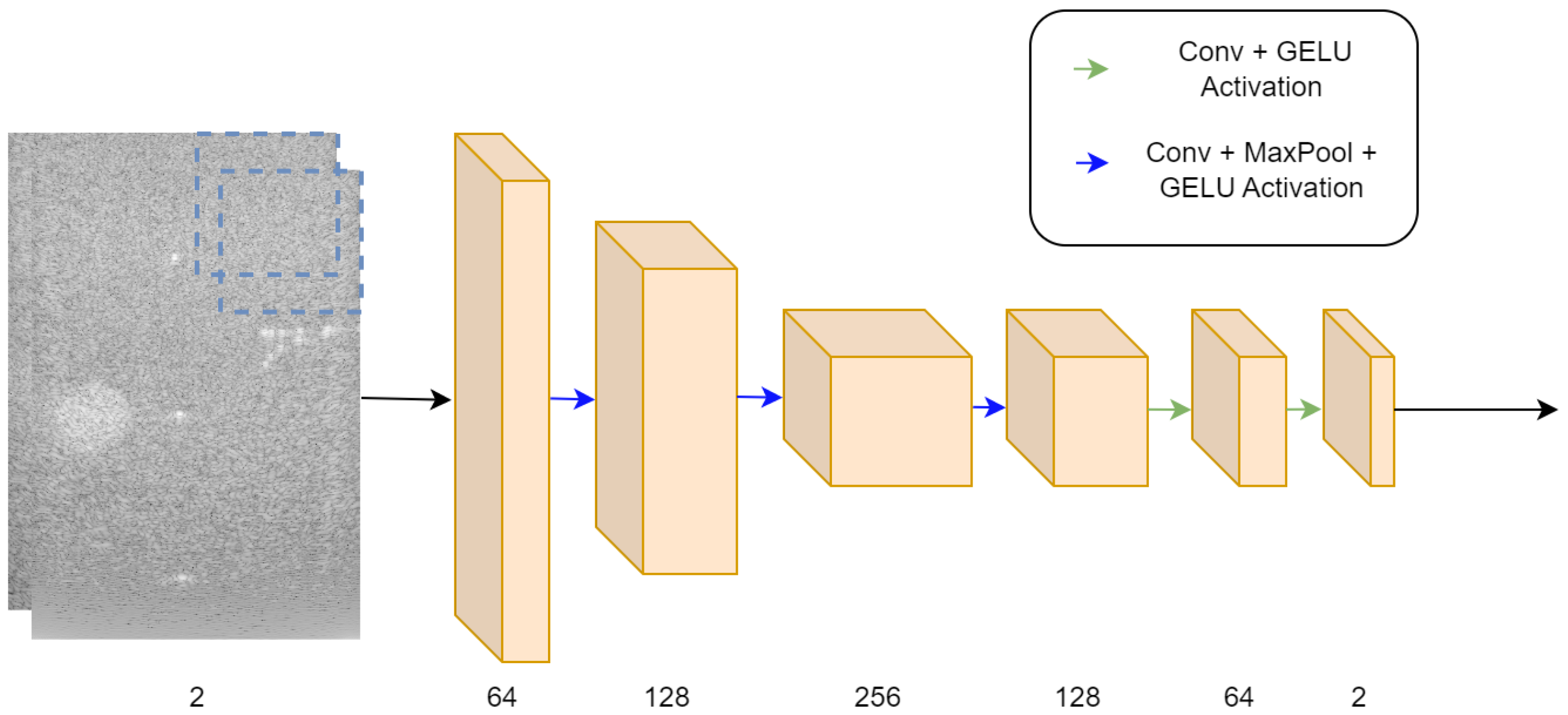
We designed a custom fully convolutional neural network (CNN) for the problem of ultrasound image formation. Our model is built from six convolutional blocks, where each block is composed of two convolutional layers, each followed by GELU [28] activation. The network input tensor shape is 2 × C × W 2 , where 2 is the input IQ dimension, C is the number of receiving channels, and W 2 is a patch with equal width and height of W flattened. Our model (Table 1, Figure 1 and Figure 2) implements a channel compounding function estimator. Each convolutional layer has a 3 × 1 kernel, where the convolutional kernel horizontal axis slides through the input tensor receive channel axis. Since our model is fully convolutional, it allows us to estimate the multi-angle acquisition patch-wise, which is significantly faster than pixel-wise.

4.2. Task Adaptive Output

The neural network can be modeled as:
I ^ = f ( X , k ; θ ) ,
where I ^ is the estimated multi-angle reconstruction, X is the pre-processed IQ (time-of-corrected and normalized) data, k is the task index, and θ is the model parameters. Our base task ( k = 0 ) is multi-angle DAS beamforming image reconstruction from a single-angle acquisition. After training for the base task, we modify the trained weights for each convolutional layer w i by applying a linear scale and bias transformation:
w i = w i s i , k + b i , k ,
where the scale and bias parameters s , b R n , n is the number of convolutional filters in layer i, and the division and sum are performed element-wise, at the channel dimension. Layer-wise per convolution filter normalization can re-adapt the learned filters to a new modified task such as denoising, image enhancement, and sub-sampling.

4.3. Controlling Task Intensity

As shown in (6), our task-specific modified convolution weights are controlled by the scale and bias parameters for each convolution kernel. For denoising tasks, such as speckle noise reduction and de-convolution, controlling the denoising effect intensity can be helpful when the user needs to see the image with a less aggressive post-processing algorithm effect. We propose a new modified version of our weight normalization scheme:
w i = w i s i , k α + α b i , k .
The new parameter α controls the intensity of the specific task, where α = 1 results in the maximal strength and α = 0 produces no effect, i.e., base task (see Figure 3).

5. Experimental Setup

5.1. Training and Evaluation Data

Our model is trained on a dataset published in [29]; from the total of 28 raw RF samples available for training, 80% are used for training and 20% for validation. We used the test set from CUBDL challenge [29] for model evaluation. Multiple different institutions acquired the data from the CUBDL challenge [23,29,30,31,32,33,34,35], it includes phantom, in vivo, and simulation samples. All the training and test data are plane wave transmission type and with 31 or 75 angles. The acquistion angles were in the range of −15° to 15° or −16° to 16°.
The raw RF data samples were acquired by three different scanner models: Verasonics Vantage 128, Verasonics Vantage 256, ULA-OP 256, and six different transducer types, giving a wide variety of acquisition to reduce overfitting. The center frequencies range from 3.1 to 8 MHz, and the sampling frequencies range from 6.25 to 78.125 MHz. Full description and information of the test and train data are available in [29].

5.2. Target Samples Generation

On each task, our neural network is trained to predict the IQ tensor of the relevant task. We train our multi-task beamformer for three different tasks:
  • Base task: Multi-angle reconstruction from single-angle acquisition. The reconstruction of multi-angle acquisition from a single-angle acquisition yields a notable increase in performance. This is attributed to the faster sensor data acquisition from a single angle compared to a multi-angle acquisition setup. Furthermore, the beamforming algorithm benefits from increased efficiency as the dimensionality of the input signal is reduced. Both the multi-angle and single-acquisition samples are generated using DAS. For the single-angle acquisition samples, the target IQ tensor is beamformed with only a single center angle of 0°.
  • Speckle noise denoising: In most commercial ultrasound devices, there is an image denoising algorithm as post-processing to the traditional beamforming after the conventional steps of envelope detection and log compression. Integrating the image-denoising step into the beamformer leads to further performance improvements. We generated our ground-truth samples for speckle noise reduction by applying [2], a variation of the Bayesian non-local-means image denoising algorithm, to the multi-angle DAS image formation pipeline output.
  • Sub-sampled channel data reconstruction: Training the beamformer to reconstruct the IQ tensor from subsampled RF data in the channel axis introduces both performance and cost improvements, as it allows the usage of ultrasound probes with fewer transducer elements. Specifically, we applied a deterministic × 2 sub-sampling to our input IQ samples; we zeroed out all the transducer element recordings at even indexes, feeding our model with only sensor reading from odd transducer element indexes.

5.3. Evaluation Metrics

The evaluation metrics of the CUBDL challenge [29] include an open-source code for evaluating ultrasound beamformers. The tests include both global and local image evaluation metrics.
  • Local image quality metrics: The challenge organizers chose a predefined region of interest (ROI) within the target images to evaluate local image quality. Those ROIs include lesions and point targets to evaluate denoising, contrast, and resolution. The final scoring of local image quality is a combination of the following metrics:
    Contrast = 20 log 10 μ 1 μ 2 .
    CNR = μ 1 μ 2 σ 1 2 + σ 2 2 .
    gCNR = 1 x min x f 1 ( x ) , f 2 ( x ) .
    SNR = μ 0 σ 0 ,
    where μ i , σ i , and f i represent the mean, standard deviation, and the histogram of ROI i. Additionally, full width at half maximum (FWHM) was calculated to measure the resolution of point targets.
  • Global image quality metrics: Global image quality metrics are used to evaluate the global beamformed image quality compared to ground-truth in terms of 1 and 2 losses, peak signal-to-noise ratio (PSNR) and normalized cross-correlation ( ρ ).
    1 = 1 N 1 N | x n y n | .
    2 = 1 N 1 N ( x n y n ) 2 .
    PSNR = 20 log 10 DynamicRange 1 N 1 N ( x n y n ) 2 .
    ρ = n ( x n μ x ) ( y n μ y ) ( n ( x n μ x ) 2 ) ( n ( y n μ y ) 2 ) ,
    where x is the envelope of the beamformed reconstruction and y is the corresponding ground-truth envelope.

5.4. Training Strategy

  • Base task: First, we train the neural network for our base task; we used AdamW optimizer [36], with a learning rate of 3 × 10 4 , β 1 = 0.9 and β 2 = 0.999 . The network is trained for 50 epochs with a step learning rate scheduler reducing the learning rate by a factor of 0.8 every 10 epochs. The batch size was set to 32. Each time-of-flight corrected RF acquisition sample is split into square patches with a width and height of 16 pixels, resulting in a total of 52,889 training samples and 13,070 validation samples. To further increase the data variety, custom data augmentations are used:
    (a)
    Row flipping: both the output and input IQ patch rows are flipped (mirrored);
    (b)
    Column flipping: both the output and input IQ patch columns are flipped (mirrored).
    Each augmentation has been applied randomly with a probability of 30%.
  • Sub-tasks: After training for the base task, we chose the best-performing weights on the validation set, and then we trained only the convolution scale and bias parameters on each sub-task. The learning rate was set to 1 × 10 5 , β 1 = 0.9 and β 2 = 0.999 , and the network convolution normalization parameters were trained for 20 epochs for each task. All the model training and experiment code was performed with the Pytorch [37] framework.
For both cases, our loss function was a linear combination of log l 1 and MS-SSIM [18] loss, given by:
L = 1 N i N | log 10 ( y i ^ ) log 10 ( y i ) | + λ SSIM ( y ^ i , y i ) ,
where y ^ is the model envelope estimation, y is the ground-truth, and SSIM is the MS-SSIM loss.
The log l 1 component of the loss is used to ensure an accurate estimation of the envelope of the signal, and the MS-SSIM component ensures that the statistical and structural properties of the image such as the contrast and luminance remains close the the ground-truth. λ is set at 0.1.

6. Results

6.1. Image Targets

This section evaluates our model qualitative performance using the test set from [29]. We also compare our result to other participants of the CUBDL [29] challenge [14,16]. We measure global and local image quality metrics described in Section 5.3.
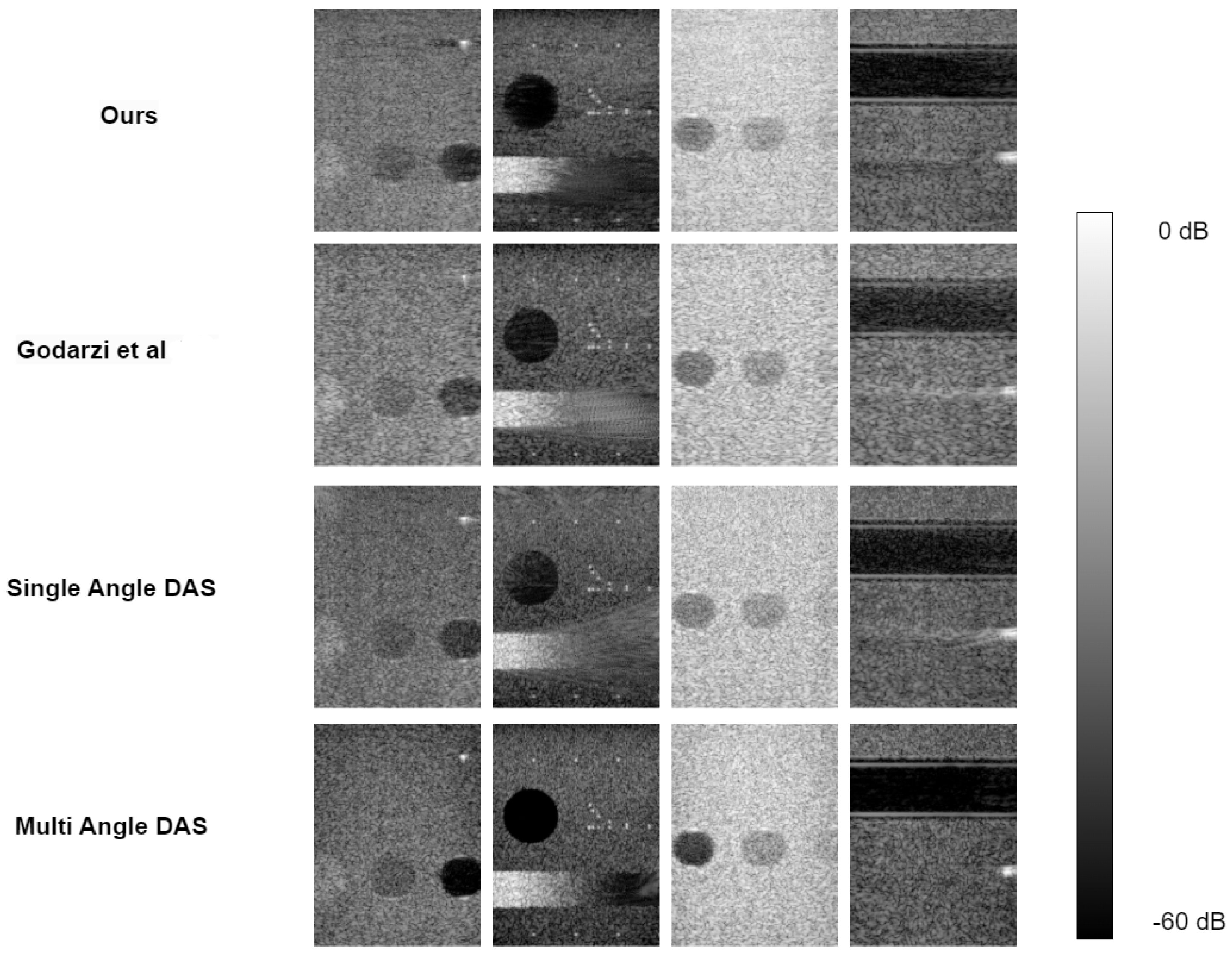
From the sample images in Figure 4 and the qualitative results in Table 2 and Table 3, we can see that our fully convolutional beamformer can reconstruct the target multi-angle acquisition with the best global image quality metrics. It is also able to outperform the other models and single-angle DAS in every local image quality measurement, except for x-axis FWHM. We suspect that, since our model reconstructs a window of 16 by 16 pixels with each forward pass, instead of a single pixel like other methods, that this slightly hurt our spatial resolution. However, that approach also led to substantial computational performance increase since, in each forward pass, our model generated 256 pixels instead of only one.
Our approach of estimating the beamformed IQ samples in patches instead of single pixel at a single forward pass, yields a fast inference. Since in each forward pass we process W 2 more pixels at a single forward pass where W is the window length.

6.2. Multi-Task Results

We evaluate our multi-task performance on two different tasks: transducer elements sub-sampling and speckle noise reduction (de-speckling).
  • Sub-sampling: We sub-sampled the input IQ cube at the channel dimension at a rate of × 2 , leaving only the elements at odd indexes. All other elements were removed (input data set to 0). We used the same test as in Section 5.4 and Section 6.1, evaluating local and global image quality compared to sub-sampled single-angle DAS. From Table 3, we notice our sub-sampled reconstruction model generates competitive global image target results relative to [14]. Also, our model suppresses the performance of single-angle sub-sampled reconstruction by a significant margin. Examining the local image quality evaluation scores in Table 2, our model still performs better than sub-sampled single-angle DAS reconstruction; however, it suffers from low contrast compared to other fully sampled reconstructions.
  • Speckle noise reduction: To evaluate speckle noise reduction, we tested both global and local image quality metrics as described in (8)–(15). Our neural network speckle reduced image is compared against the speckle denoising algorithm in [2] applied to multi-angle (ground-truth) and single-angle reconstruction. Inspecting the local image quality metrics, from our results reported in Table 4, we see our model out-performs the speckle reduced single-angle DAS in every measurement except for contrast. The global image quality test results in Table 5 indicate our model outperforms the speckle denoised single-angle DAS generated image regarding global image quality metrics by a significant amount. In comparison to the ground-truth multi-angle DAS with speckle reduction, our reconstruction show an inferior contrast; however, it remains on par or better in other matrices, specifically gCNR and SpeckleSNR.

7. Discussion

For the fundamental task of single-angle reconstruction from multi-angle acquisition, our research has substantiated that our model outperforms the CUBDL challenge competition winner regarding global image quality metrics. Specifically, our model shows state-of-the-art results with all the global image quality metrics, and with the local image quality metrics, our model produces results that out-perform CUBDL challenge winner by noticeable gap in every measure except for spatial resolution along the x axis (x—full with at half maximum).
The network proposed by Goudarzi et al. [14] learns to map between a window of IQ from a single-angle acquisition to a single pixel in the center of the window. They trained the model to estimate the corresponding center pixel in multi-angle acquisition. Thus, in each forward pass, the output is a single pixel. Our model is trained to learn a mapping between a patch of single-angle acquisition IQ data to a patch of multi-angle beamformed IQ data. Thus, since every layer applies convolution in the channel domain, our model predictions are less focused on a single pixel than the MobileNetV2 beamformer.
The MobileNetV2 model can be parallelized in a practical implementation, thus reconstructing multiple pixels with a single parallelized forward pass. Due to memory limitations, parallelizing all the pixels in an ultrasound scan is not feasible in current technology. Since our neural network reconstructs a patch of pixels within a single forward pass, parallelization of our model to reconstruct the entire image is more feasible.
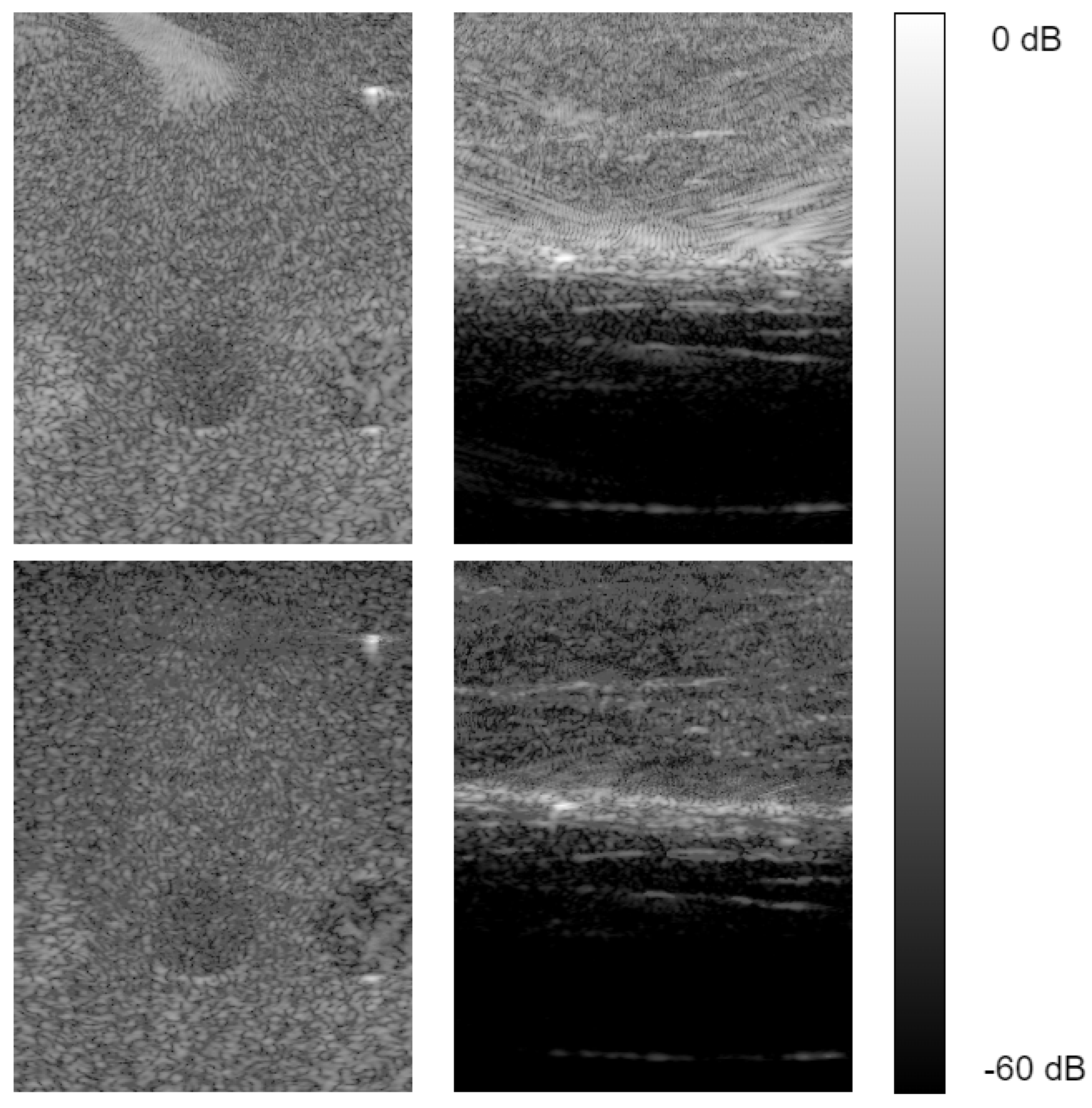
Unlike conventional image processing tasks that are typically executed by 2D convolutional neural networks, beamforming aims to compound multiple channels of the received signal. Therefore, implementing this objective involves utilizing a one-dimensional convolutional kernel that slides exclusively through the channel dimension. One-dimensional convolution kernels are also faster in terms of computational resources, since fewer multiplication and sum operations are performed. Also, they are lighter in terms of parameter count. We then fitted the mean and variance parameters of the layer weight normalization to two different tasks: sub sampling and speckle noise reduction. Our model outperforms sub-sampled single and delay and sum reconstruction in every global and local image quality metric measurement. The sample images in Figure 5 show our sub-sampled reconstruction model ability to remove scattering, resulting from noisy measurement compared to sub-sampled delay and sum reconstruction. This property of our beamformer is also observable with the global image quality metrics, where our noise measurements, such as PSNR and ρ , are significantly better than the sub-sampled DAS reconstruction.
For the next task, we compared our model against single-angle delay and sum with a speckle noise reduction post-processing. From Table 4 we can conclude that our model produces the best results in local image quality metrics compared to single-plane wave reconstruction with speckle denoising post-processing, except for a small gap in contrast. With the global image quality metrics, our model out performs the single-angle DAS in every measurement by a significant amount.
Our model is trained using the CUBDL [23] dataset, which consists of ultrasound channel data from various ultrasound machines and probe configurations. These machines and configurations have different center frequencies and sampling frequencies. Additionally, the dataset includes simulated data, phantom scans, and in vivo data. This diverse dataset proves the robustness of our model across various experimental settings for plane wave ultrasound image formation. However, since we narrowed our work to plane wave ultrasound, our model is limited to only plane wave ultrasound beamforming, and is not suitable for other formation methods like focused transmit.

8. Conclusions

To conclude, we proposed a fully convolutional neural network for the problem of ultrasound beamforming. We began by training our model for multi-angle reconstruction from a single-angle acquisition. We then adjusted the learned convolutional filters for sub-sampling and speckle noise reduction with our proposed layer-wise convolution filter weight normalization. From the results, we noticed our approach to multitask beamforming has shown the best results in terms of global and local image quality metrics. We chose a patch-wise beamformer, thus losing the specificity of a pixel-wise beamformer while improving the computational requirements. Future research can explore the potential of enhancing the architecture to achieve improved computational performance while carefully balancing the trade off between local image quality, specifically contrast.

Author Contributions

Conceptualization, E.D. and I.C.; methodology, E.D. and I.C.; software, E.D.; validation, E.D. and I.C.; formal analysis, E.D.; investigation, E.D. and I.C.; resources, E.D. and I.C.; data curation, E.D.; writing—original draft preparation, E.D. and I.C.; writing—review and editing, E.D. and I.C.; visualization, E.D.; supervision, I.C.; project administration, E.D. and I.C. All authors have read and agreed to the published version of the manuscript.

Funding

This research received no external funding.

Data Availability Statement

The data presented in this study are available on request from the corresponding author.

Conflicts of Interest

The authors declare no conflict of interest.

Abbreviations

The following abbreviations are used in this manuscript:
DASDelay and sum
MVDRMinimum variance distortionless response
CNNConvolutional neural network
IQIn-phase, Quadrature

References

  1. Karthikeyan, S.; Manikandan, T.; Nandalal, V.; Mazher Iqbal, J.; Babu, J.J. A Survey on Despeckling Filters for Speckle Noise Removal in Ultrasound Images. In Proceedings of the 2019 3rd International conference on Electronics, Communication and Aerospace Technology (ICECA), Coimbatore, India, 12–14 June 2019; pp. 605–609. [Google Scholar] [CrossRef]
  2. Coupe, P.; Hellier, P.; Kervrann, C.; Barillot, C. Nonlocal means-based speckle filtering for ultrasound images. IEEE Trans. Image Process. 2009, 18, 2221–2229. [Google Scholar] [CrossRef] [PubMed]
  3. Sagheer, S.V.M.; George, S.N. Denoising of medical ultrasound images based on non-local similarity: A low-rank approach. In Proceedings of the TENCON 2017—2017 IEEE Region 10 Conference, Penang, Malaysia, 5–8 November 2017; pp. 176–181. [Google Scholar] [CrossRef]
  4. Lan, Y.; Zhang, X. Real-Time Ultrasound Image Despeckling Using Mixed-Attention Mechanism Based Residual UNet. IEEE Access 2020, 8, 195327–195340. [Google Scholar] [CrossRef]
  5. Dietrichson, F.; Smistad, E.; Ostvik, A.; Lovstakken, L. Ultrasound Speckle Reduction Using Generative Adversial Networks. In Proceedings of the 2018 IEEE International Ultrasonics Symposium, (IUS), Kobe, Japan, 22–25 October 2018; pp. 1–4. [Google Scholar] [CrossRef]
  6. Khor, H.G.; Ning, G.; Zhang, X.; Liao, H. Ultrasound Speckle Reduction Using Wavelet-Based Generative Adversarial Network. IEEE J. Biomed. Health Inform. 2022, 26, 3080–3091. [Google Scholar] [CrossRef] [PubMed]
  7. Lee, H.; Lee, M.H.; Youn, S.; Lee, K.; Lew, H.M.; Hwang, J.Y. Speckle Reduction via Deep Content-Aware Image Prior for Precise Breast Tumor Segmentation in an Ultrasound Image. IEEE Trans. Ultrason. Ferroelectr. Freq. Control 2022, 69, 2638–2650. [Google Scholar] [CrossRef]
  8. Mozaffarzadeh, M.; Mahloojifar, A.; Periyasamy, V.; Pramanik, M.; Orooji, M. Eigenspace-Based Minimum Variance Combined With Delay Multiply and Sum Beamformer: Application to Linear-Array Photoacoustic Imaging. IEEE J. Sel. Top. Quantum Electron. 2019, 25, 1–8. [Google Scholar] [CrossRef]
  9. Alzubaidi, L.; Bai, J.; Al-Sabaawi, A.; Santamaría, J.; Albahri, A.S.; Al-dabbagh, B.S.N.; Fadhel, M.A.; Manoufali, M.; Zhang, J.; Al-Timemy, A.H.; et al. A survey on deep learning tools dealing with data scarcity: Definitions, challenges, solutions, tips, and applications. J. Big Data 2023, 10, 46. [Google Scholar] [CrossRef]
  10. Alammar, Z.; Alzubaidi, L.; Zhang, J.; Li, Y.; Lafta, W.; Gu, Y. Deep Transfer Learning with Enhanced Feature Fusion for Detection of Abnormalities in X-ray Images. Cancers 2023, 15, 4007. [Google Scholar] [CrossRef] [PubMed]
  11. Chen, C.; Zhou, K.; Wang, Z.; Xiao, R. Generative Consistency for Semi-Supervised Cerebrovascular Segmentation From TOF-MRA. IEEE Trans. Med. Imaging 2023, 42, 346–353. [Google Scholar] [CrossRef] [PubMed]
  12. SORENSON, T. A method of establishing groups of equal amplitude in plant sociology based on similarity of species content, and its application to analysis of vegetation on Danish commons. Kong Dan Vidensk. Selsk. Biol. Skr. 1948, 5, 1–5. [Google Scholar]
  13. Luijten, B.; Cohen, R.; de Bruijn, F.J.; Schmeitz, H.A.W.; Mischi, M.; Eldar, Y.C.; van Sloun, R.J.G. Adaptive Ultrasound Beamforming Using Deep Learning. IEEE Trans. Med. Imaging 2020, 39, 3967–3978. [Google Scholar] [CrossRef] [PubMed]
  14. Goudarzi, S.; Asif, A.; Rivaz, H. Ultrasound Beamforming using MobileNetV2. In Proceedings of the 2020 IEEE International Ultrasonics Symposium (IUS), Las Vegas, NV, USA, 7–11 September 2020; pp. 1–4. [Google Scholar] [CrossRef]
  15. Sandler, M.; Howard, A.; Zhu, M.; Zhmoginov, A.; Chen, L.C. MobileNetV2: Inverted Residuals and Linear Bottlenecks. In Proceedings of the 2018 IEEE/CVF Conference on Computer Vision and Pattern Recognition, Salt Lake City, UT, USA, 18–23 June 2018; pp. 4510–4520. [Google Scholar] [CrossRef]
  16. Rothlübbers, S.; Strohm, H.; Eickel, K.; Jenne, J.; Kuhlen, V.; Sinden, D.; Günther, M. Improving Image Quality of Single Plane Wave Ultrasound via Deep Learning Based Channel Compounding. In Proceedings of the 2020 IEEE International Ultrasonics Symposium (IUS), Las Vegas, NV, USA, 7–11 September 2020; pp. 1–4. [Google Scholar] [CrossRef]
  17. Liebgott, H.; Rodriguez-Molares, A.; Cervenansky, F.; Jensen, J.; Bernard, O. Plane-Wave Imaging Challenge in Medical Ultrasound. In Proceedings of the 2016 IEEE International Ultrasonics Symposium (IUS), Tours, France, 18–21 September 2016; pp. 1–4. [Google Scholar] [CrossRef]
  18. Wang, Z.; Simoncelli, E.; Bovik, A. Multiscale structural similarity for image quality assessment. In Proceedings of the Thrity-Seventh Asilomar Conference on Signals, Systems & Computers, Pacific Grove, CA, USA, 9–12 November 2003; Volume 2, pp. 1398–1402. [Google Scholar] [CrossRef]
  19. Bhatt, M.; Nair, A.A.; Kempski, K.M.; Lediju Bell, M.A. Multi-task learning for ultrasound image formation and segmentation directly from raw in vivo data. In Proceedings of the 2020 IEEE International Ultrasonics Symposium (IUS), Las Vegas, NV, USA, 7–11 September 2020; pp. 1–4. [Google Scholar] [CrossRef]
  20. Ronneberger, O.; Fischer, P.; Brox, T. U-Net: Convolutional Networks for Biomedical Image Segmentation. In Proceedings of the Medical Image Computing and Computer-Assisted Intervention—MICCAI 2015; Navab, N., Hornegger, J., Wells, W.M., Frangi, A.F., Eds.; Springer International Publishing: Cham, Switzerland, 2015; pp. 234–241. [Google Scholar]
  21. Khan, S.; Huh, J.; Ye, J.C. Switchable Deep Beamformer For Ultrasound Imaging Using Adain. In Proceedings of the 2021 IEEE 18th International Symposium on Biomedical Imaging (ISBI), Nice, France, 13–16 April 2021; pp. 677–680. [Google Scholar] [CrossRef]
  22. Huang, X.; Belongie, S. Arbitrary Style Transfer in Real-time with Adaptive Instance Normalization. In Proceedings of the IEEE International Conference on Computer Vision (ICCV), Venice, Italy, 22–29 October 2017. [Google Scholar]
  23. Bell, M.A.L.; Huang, J.; Hyun, D.; Eldar, Y.C.; van Sloun, R.; Mischi, M. Challenge on Ultrasound Beamforming with Deep Learning (CUBDL). In Proceedings of the 2020 IEEE International Ultrasonics Symposium (IUS), Las Vegas, NV, USA, 7–11 September 2020; pp. 1–5. [Google Scholar] [CrossRef]
  24. Capon, J. High-resolution frequency-wavenumber spectrum analysis. Proc. IEEE 1969, 57, 1408–1418. [Google Scholar] [CrossRef]
  25. Mehdizadeh, S.; Austeng, A.; Johansen, T.F.; Holm, S. Eigenspace Based Minimum Variance Beamforming Applied to Ultrasound Imaging of Acoustically Hard Tissues. IEEE Trans. Med. Imaging 2012, 31, 1912–1921. [Google Scholar] [CrossRef] [PubMed]
  26. Matrone, G.; Savoia, A.S.; Caliano, G.; Magenes, G. The Delay Multiply and Sum Beamforming Algorithm in Ultrasound B-Mode Medical Imaging. IEEE Trans. Med. Imaging 2015, 34, 940–949. [Google Scholar] [CrossRef] [PubMed]
  27. Matrone, G.; Ramalli, A.; Savoia, A.S.; Tortoli, P.; Magenes, G. Improved resolution and crosstalk rejection in Multi-Line Transmit ultrasound imaging using Delay Multiply and Sum beamforming. In Proceedings of the 2016 IEEE International Ultrasonics Symposium (IUS), Tours, France, 18–21 September 2016; pp. 1–4. [Google Scholar] [CrossRef]
  28. Hendrycks, D.; Gimpel, K. Gaussian Error Linear Units (GELUs). arXiv 2020, arXiv:1606.08415. [Google Scholar]
  29. Hyun, D.; Wiacek, A.; Goudarzi, S.; Rothlübbers, S.; Asif, A.; Eickel, K.; Eldar, Y.C.; Huang, J.; Mischi, M.; Rivaz, H.; et al. Deep Learning for Ultrasound Image Formation: CUBDL Evaluation Framework and Open Datasets. IEEE Trans. Ultrason. Ferroelectr. Freq. Control 2021, 68, 3466–3483. [Google Scholar] [CrossRef] [PubMed]
  30. Wiacek, A.; Rindal, O.M.H.; Falomo, E.; Myers, K.; Fabrega-Foster, K.; Harvey, S.; Lediju Bell, M.A. Robust Short-Lag Spatial Coherence Imaging of Breast Ultrasound Data: Initial Clinical Results. IEEE Trans. Ultrason. Ferroelectr. Freq. Control 2019, 66, 527–540. [Google Scholar] [CrossRef] [PubMed]
  31. Li, Z.; Wiacek, A.; Bell, M.A.L. Beamforming with deep learning from single plane wave RF data. In Proceedings of the 2020 IEEE International Ultrasonics Symposium (IUS), Las Vegas, NV, USA, 7–11 September 2020; pp. 1–4. [Google Scholar] [CrossRef]
  32. Rindal, O.M.H.; Aakhus, S.; Holm, S.; Austeng, A. Hypothesis of Improved Visualization of Microstructures in the Interventricular Septum with Ultrasound and Adaptive Beamforming. Ultrasound Med. Biol. 2017, 43, 2494–2499. [Google Scholar] [CrossRef] [PubMed]
  33. Zhang, X.; Li, J.; He, Q.; Zhang, H.; Luo, J. High-Quality Reconstruction of Plane-Wave Imaging Using Generative Adversarial Network. In Proceedings of the 2018 IEEE International Ultrasonics Symposium (IUS), Kobe, Japan, 22–25 October 2018; pp. 1–4. [Google Scholar] [CrossRef]
  34. Rodriguez-Molares, A.; Rindal, O.M.H.; D’hooge, J.; Måsøy, S.E.; Austeng, A.; Lediju Bell, M.A.; Torp, H. The Generalized Contrast-to-Noise Ratio: A Formal Definition for Lesion Detectability. IEEE Trans. Ultrason. Ferroelectr. Freq. Control 2020, 67, 745–759. [Google Scholar] [CrossRef] [PubMed]
  35. Rindal, O.M.H.; Austeng, A.; Fatemi, A.; Rodriguez-Molares, A. The Effect of Dynamic Range Alterations in the Estimation of Contrast. IEEE Trans. Ultrason. Ferroelectr. Freq. Control 2019, 66, 1198–1208. [Google Scholar] [CrossRef] [PubMed]
  36. Loshchilov, I.; Hutter, F. Fixing Weight Decay Regularization in Adam. arXiv 2017, arXiv:1711.05101. [Google Scholar]
  37. Paszke, A.; Gross, S.; Chintala, S.; Chanan, G.; Yang, E.; DeVito, Z.; Lin, Z.; Desmaison, A.; Antiga, L.; Lerer, A. Automatic Differentiation in PyTorch. 2017. Available online: https://openreview.net/pdf?id=BJJsrmfCZ (accessed on 26 August 2023).
Figure 1. The proposed multi-task beamforming pipeline: raw RF sensor data are scaled to the [−1, 1] range, then Hilbert transform and time-of-flight correction is applied. The time-of-flight corrected IQ is fed into a neural network that reconstructs the beam summed multitask IQ data according to the specific task.
Information 14 00582 g001
Figure 2. The proposed multitask beamforming neural network: pre-processed IQ data are fed to our fully convolutional neural network. The network outputs an IQ estimation corresponding to a task-specific output.
Information 14 00582 g002
Figure 3. Controlling the de-speckling effect. The output is identical to the base task for α = 0 . The output is a full task-specific effect for α = 1 . By choosing different α values, we can control the amount of convolution kernel weights scale and bias, and hence control the de-speckling effect.
Information 14 00582 g003
Figure 4. Test set samples of our base task multi-angle reconstruction from single-angle acquisition. Our model can remove most of the noise and scattering log S p e c k l e S N R of 2.299 and ρ of 0.93—outperforming all the other challenge participants (Table 2 and Table 3). Adapt from Goudarzi et al. [14].
Information 14 00582 g004
Figure 5. Image reconstruction samples of sub-sampled data, at the channel dimension. Our model can reduce noise from noisy measurements due to the reduced number of elements used. Also, it can generate an image with higher contrast compared to sub-sampled single-angle reconstruction. Both images are samples from CUBDL [23] test set.
Information 14 00582 g005
Table 1. Fully convolutional beamformer architecture.
Layer TypeInput ShapeOutput Shape
ConvBlock 2 × N c × 256 64 × N c × 256
Max pooling 64 × N c × × 256 64 × N c 2 × 256
ConvBlock 64 × N c 2 × 256 128 × N c 2 × 256
max pooling 128 × N c 2 × 256 128 × N c 4 × 256
ConvBlock 128 × N c 4 × 256 256 × N c 4 × 256
max pooling 256 × N c 4 × 256 256 × N c 8 × 256
ConvBlock 256 × N c 8 × 256 128 × N c 8 × 256
ConvBlock 128 × N c 8 × 256 64 × N c 8 × 256
ConvBlock 64 × N c 8 × 256 2 × N c 8 × 256
Table 2. CUBDL [29] test set local results. Local image quality results from the CUBDL test set. Our model outperforms the competitors in the challenge by a significant margin in every measure except spatial resolution along the x-axis (x fwhm).
ModelContrast dBSpeckle CNRgCNR log Speckle SNR x Fwhmz Fwhm
Goudarzi et al. [14]−13.771.3450.8141.8270.00030.0004
Single Plane−10.51.050.6741.850.00040.0004
Ours−15.841.6320.882.2990.00050.0003
Ours— × 2 Sub Sampled−5.071.0830.621.940.00060.0003
Single Plane— × 2 Sub Sampled−4.950.5420.3941.8420.00040.0004
Ground-Truth—Multi-Plane−24.701.530.9461.8060.00040.0003
Table 3. CUBDL [29] test set global results. Global image quality results on multi-angle DAS reconstruction from single-angle acquisition, and image reconstruction from 2× sub-sampled channel data. our model produces the best results in every measurement. Additionally, for the task of image reconstruction from sub-sampled channel data, our model out performs DAS algorithm.
Model 1 log 1 2 log 2 PSNR ρ
Goudarzi et al. [14]0.030.420.050.5629.100.91
Single Plane0.030.390.0420.5330.360.93
Ours0.0290.360.04080.4930.40.93
Ours— × 2 Sub Sampled0.0350.410.05040.5528.520.9
Single Plane— × 2 Sub Sampled0.04330.5250.0590.727.430.86
Table 4. Speckle denoising local image results.
ModelContrast dBSpeckle CNRgCNRSpeckle SNR
Single-Angle + speckle reduction−10.51.050.6741.85
Ours: speckle reduction−10.071.6730.8853.17
Multi-Angle + speckle reduction (ground-truth)−25.62.4230.982.713
Table 5. Speckle denoising global image results.
Model log 1 log 2 PSNR ρ
Single Plane + speckle reduction0.571.0724.80.593
Ours-speckle reduction0.30.4129.010.92
Disclaimer/Publisher’s Note: The statements, opinions and data contained in all publications are solely those of the individual author(s) and contributor(s) and not of MDPI and/or the editor(s). MDPI and/or the editor(s) disclaim responsibility for any injury to people or property resulting from any ideas, methods, instructions or products referred to in the content.