Article

Providing a User Extensible Service-Enabled Multi-Fidelity Hybrid Cloud-Deployable SoS Test and Evaluation (T&E) Infrastructure: Application of Modeling and Simulation (M&S) as a Service (MSaaS)

The MITRE Corporation, 7515 Colshire Dr, McLean, VA 22102, USA
*
Author to whom correspondence should be addressed.
Information 2023, 14(10), 528; https://doi.org/10.3390/info14100528
Submission received: 14 August 2023 / Accepted: 5 September 2023 / Published: 28 September 2023
(This article belongs to the Special Issue Simulation Modeling Theory and Practice: Pushing the Boundaries)

Abstract

:
Autonomous and AI-enabled systems present a challenge for integration within the System of Sys-tems (SoS) paradigm. A full system of systems (SoS) testbed is necessary to verify the integrity of a given system and preserve the modularization and accountability of its constituent systems. This integrated system needs to support iterative, continuous testing and development. This need war-rants the development of a virtual environment that provides the ground truth in a simulated sce-nario, interfaces with real-world data, and uses various domain-specific and domain-agnostic simulation systems for development, testing, and evaluation. These required features present a non-trivial challenge wherein constructive models and systems at different levels of fidelity need to interoperate to advance the testing, evaluation, and integration of complex systems. Such a virtual and constructive SoS architecture should be independent of the underlying computational infra-structure but must be cloud-enabled for wider integration of AI-enabled software components. This paper will present a modular Simulation, Experimentation, Analytics, and Test (SEAT) Lay-ered Architecture Framework, a 10-step methodology. This paper will also demonstrate a case study of a hybrid cloud-enabled simulation SoS that allows extensibility, composability, and de-ployability in different target environments.

1. Introduction

Success in future conflicts depends on multiple systems being able to integrate and operate as a broader system of systems. A foundational capability for future autonomous systems development is an open systems architecture that allows integration, interoperability, and composability of autonomous software/systems tools to perform Test, Evaluation, Verification, and Validation (TEVV). Virtual assessment tools cannot be focused on a single system that just tests interoperability. A multi-fidelity system of systems (SoS) testbed is necessary to verify the integration of a given system with an existing SoS Modeling and Simulation (M&S) ecosystem. The M&S ecosystem must preserve the modularization and accountability of its constituent systems. It is necessary for autonomous/AI-enabled systems to have a scalable and flexible foundation for integrating, testing, and evaluating autonomous tools and capabilities within a multi-domain environment, incorporating systems from the Army, Navy, Marine Corps, and Air Force to perform SoS engineering (SoSE) effectively [1]. Multi-domain Operations (MDO) and associated SoSE engineering are not straightforward due to many moving parts [2,3]. M&S has been considered a key instrument to facilitate integration, interoperability, and T&E at various phases of SoSE [4,5]. SoSE through service facades and hybrid container architectures is one of the approaches explored to enable M&S-based T&E [6]. Such architectures need to be readily deployable to target cloud platforms such as PlatformONE [7] or Amazon Web Service (AWS) Gov. Cloud [8].
Engineering an on-demand cloud-enabled computational infrastructure for deploying an extensive SoS architecture is a non-trivial task [9]. At an organizational level, this often results in a lot of duplicated effort as every project reinvents the infrastructure wheel to suit their needs. To help address this issue, MITRE introduced the modular Simulation, Experimentation, Analytics, and Test (SEAT) Layered Architecture Framework to develop cloud-enabled federated Modeling and Simulation (M&S) architectures [10]. In the past 3 years, MITRE has applied SEAT and refined the methodology to onboard different M&S SoS architectures, incorporating a plethora of tools and a variety of middleware applications. We have: (1) deployed an existing federated High-Level Architecture (HLA)-based container-implemented distributed simulation application and packaged it for an on-demand cloud deployment; and (2) integrated autonomy-focused high-fidelity tools such as Gazebo, ArduPilot and a custom Command and Control (C2) application and deployed them in a cloud environment.
This paper describes the SEAT Architecture Framework in more detail, a 10-step methodology, and an associated use case: Expedient Leader Follower (ExLF) using Unmanned Aerial Vehicle (UAVs) and Unmanned Ground Vehicles (UGVs) in a breach mission scenario demonstrates the value of the approach. The original use case, comprising only the MITRE-developed Netlogo-based ESimP model [10], is augmented to demonstrate the current SEAT architecture, various service facades, and methodology using an improvised high-fidelity, low-resolution ESimP mission-level model and a high-fidelity, high-resolution gaming Unreal Engine entity behavior model that models UGVs.
The paper is organized as follows: Section 2 describes related work in the M&S, Cloud, and Joint experimentation engineering communities. Section 3 presents the M&S as a service paradigm. Section 4 describes the SEAT framework. Section 4 discusses the SEAT engineering methodology. Section 5 describes the 10-step SEAT engineering methodology. Section 6 describes the on-demand cloud provisioning infrastructure using the MITRE Symphony™ platform, followed by SEAT workflow engineering in Section 7. Section 8 describes the FY22 case study for Expedient Leader Follower (ExLF) with Unreal. Section 9 discusses the SEAT approach and deployment options. Finally, Section 10 presents conclusions and future work.

2. Related Work

There are multiple threads of work related to the rapid development, integration, and deployment of simulation-based environments for experimentation, analysis, and testing across the simulation community. An exhaustive investigation of these threads is beyond the scope of this paper, but it is worthwhile to introduce the body of work to recognize this evolving technology area and acknowledge the challenges, successes, and lessons learned from the related work.
A repository of documentation on the challenges and progress within simulation interoperability and associated architectures, environments, and simulation federation standards is managed and maintained by the Simulation Interoperability Standards Organization (SISO) [11]. The organization has long been a foundational source of simulation interoperability standards, and the SISO Standards Activity Committee (SAC) is recognized as the Computer/Simulation Interoperability (C/SI) Standards Committee by the IEEE. The C/SI sponsors three cornerstone simulation interoperability standards that are fundamental to data modeling, runtime management of simulation data, and distributed simulation development. These standards include IEEE Std 1278TM—Distributed Interactive Simulation (DIS) [12]; IEEE Std 1516TM High Level Architecture (HLA) [12,13,14,15]; and the IEEE 1730TM—Distributed Simulation Engineering and Execution Process (DSEEP) [16,17]. SISO manages over 20 standards, including the C2 Simulation Standard (C2SIM) (SISO-STD-019-2020) [18] and the Space Reference Federation Object Model (SpaceFOM) [11]. The organization is also actively studying other simulation areas for standardization, such as electronics warfare and simulation scalability. The body of work centers on the long-standing objective of defining and achieving valid model and simulation interoperability for use within a wide range of operational domains, including testing, training, and experimentation.
In addition to the broadly-based industry standards, there has been more narrow-domain consensus refining and customizing the general simulation interoperability standards to meet stricter performance requirements, such as within the test and evaluation (T&E) domain. An example here includes the Tests and Training Enabling Architecture (TENA) developed by the Test Resource Management Center (TRMC) to support domain-specific distributed Live, Virtual, and Constructive (LVC) simulation test-harness requirements [19,20].
This evolution of independent integrating architectures has led to inconsistencies and complexity when trying to bridge, connect, and validate legacy models and simulations developed using one or more of the existing integrating architectures. The complexities span across data model specification, runtime data model communication, infrastructure compute technologies, and on-premise or cloud deployment technologies [21,22].
A promising mechanism to manage the complexity across the semantic, technical, and procedural dimensions is that of service- and microservice-oriented architecture definition and specification. Our work demonstrates that by using and customizing SOA processes, tools, and technologies, one can address semantic interface development and composable computation challenges through virtualization, containerization, and cloud-native constructs. The first step in this process, a conceptual reference model of M&S as a Service (MSaaS), captures a taxonomy and reference for M&S services, allowing further definition and development of services supporting M&S suppliers and M&S users (NATO MSG-136) [23,24]. An instantiation of such a Our work shown here takes the general reference architecture and adds definition, integrates workflow processes through connectivity to Continuous Integration and Continuous Development (CI/CD) pipelines, and provides specific implementation and deployment details that are consistent with the overarching M&S and SOA principles.
The specific highlighted lessons learned from past and ongoing efforts from conceptual and reference models to specific persistent simulation environments involve the need for:
  • Persistent simulation environments that allow external simulation federates to “easily” integrate into the existing environment(s);
  • Virtual Machine (VM) and cloud-deployable simulation instances that are more easily distributed and accessed by authorized users and roles;
  • The Risk Management Framework and the ability to support program, service, and DoD-level software Authority to Operate (ATO) on trusted networks (McKeown 2022);
  • Software factories provide not only configuration management tools but also wholistic CI/CD pipelines as part of the DevSecOps strategy.
Two specific projects and labs will be mentioned here as providing substantive lessons learned. Using the “Always On—On Demand” simulation environment developed to support the development, test, and training of operational networks and net-centric systems [25] and the Battle Lab Collaborative Simulation Environment (BLCSE) [26].
These simulation environments were formulated to create a persistent simulation environment by integrating existing simulation tools to support accessible analysis, experimentation, and integration of systems under test or as part of exercise-based training. The simulations, to include but not be limited to ground maneuvers, direct and indirect fires, network and cyber simulations, etc., were integrated and able to stimulate and be stimulated by real-world C2 decision support tools. The simulation environments were accessible via DoD-standardized networks and used in support of experimentation, operational testing, and training events. As part of this paper, the primary lessons learned from these types of persistent environments include:
  • There is a need for a persistent set of expert simulationists to setup, run, and evolve the specific simulation federates as well as the overall federation to support events, mitigate and fix software and simulation bugs, develop and employ consistent datasets, and help report, deliver, and understand the results;
  • A standardized and well-defined common and interaction data model is necessary to allow integration across the simulation federates and to drive the simulation/stimulation interfaces to the C2 community;
  • A standardized process with appropriate automation that is co-owned by security accreditation professions is essential to support any type of DoD security and network authorization in order to connect to trusted networks;
  • The ability to evolve and enhance the simulation tools and to integrate additional functionality with new or existing tool modifications to support new cyber and/or other non-kinetic capabilities is critical to US warfighting advantage.
We apply the lessons learned and present a cohesive framework and methodology.

3. M&S as a Service Paradigm and Fidelity Management

A service, fundamentally, is a functional aspect of any component that it offers to the external world. Technically, in the computer systems engineering domain, a service specification includes the input/output (or request/response) data along with a semantic connotation of the offering. A service specification is often considered a subcomponent in the Service-Oriented Architecture (SOA) paradigm, and a service specification takes the form of a service interface specification. A service interface, accordingly, hides the transformation of input data into output data to deliver the outcome of the functional behavior. A service separates the “what” (data and semantic function) from the “how” for the external world.
Any system (both natural and artificial) can be expressed as a collection of service interfaces at different fidelities and resolutions. Fidelity can be construed as a set of features (or services) a system uses to provide the functional aspect of that system. Resolution can be construed as the data precision required for each of the features (or services) to furnish detail about that feature. An efficient system model strikes a good balance between fidelity and resolution, and experienced modelers select appropriate fidelity and resolution to answer the question that the model is designed for, albeit with cost/labor tradeoffs.
The notion that a system offers “service” has an implicit connotation that the system has become a “server” that fulfills a service “request” using input data with a service “response” returned through output data. This impacts the overall system architecture because transforming a system and its various interactions into services and making the system available for more than one client (who makes service requests) is a non-trivial effort. From a tightly coupled point-to-point system with defined data interfaces, a system is now transformed into a set of loosely coupled functions (services) that may be invoked in an isolated and concurrent manner. Managing the system state (i.e., a collection of variables and their values at a certain time in the simulation execution or in an LVC exercise) and accordingly, the model’s state, becomes a challenging issue in this client-server paradigm when applied to M&S architectures.
Modeling and simulation are two distinct activities. Consequently, Modeling as a Service (MaaS) and Simulation as a Service (SIMaaS) are distinct as well. In the current effort reported here, we take these two distinct activities and call them MSaaS. MaaS deals with model engineering and managing fidelity and resolution through layered service specification architectures. SIMaaS deals with the development of services that offer and control various simulator tools (as black-box systems) as simulation servers, along with the underlying hardware infrastructure that runs these servers. Figure 1 depicts this concept for an SoS model for a multi-agent system. A constituent system/asset/agent/tool is represented as System Service Application Programming Interfaces (APIs), which allow interacting with a system with defined input/output specifications made available as a set of service functions. An API marks the functional boundary of the system and can be computationally implemented through standards such as Web Service Description Language (WSDL) in the client-server paradigm. The functional description of the system can be decomposed in a layered manner and, accordingly, APIs can be organized into multi-layered service APIs. The MaaS API specifies behavioral fidelity in a layered manner. Each layer on the right side (Figure 1 in blue) is built on the foundation of the layer beneath it. The annotations on the right side also show an example of various services for a typical leader-follower multi-agent system. The System/Asset/Agent Model/Tool layer (in black on the right side) is the SIMaaS layer that makes tool control possible through various service functions.
Each of the API layers, for both MaaS and SIMaaS, needs to be developed through standards-based specifications. These standards include Web Service Description Language (WSDL) using Simple Object Access Protocol (SOAP) or emerging open API standards like Open API 3.0 [27], implemented by Swagger toolset [28], and event-driven Async API ([29]. While WSDL/SOAP is dated and used in legacy implementations, OpenAPI/Swagger is REST-based, and Async-API is message-based. Regardless, all provide mechanisms to specify software components behind a functional service API façade. Having an API-first approach (OUSD 2020) [30] allows the software systems (both models and simulators, in our case) to publish the functional aspects of the system and facilitates rapid development, integration, and interoperability.
The benefits of API-based system engineering are manyfold. API-enabled systems allow other community players to design their systems to the advertised APIs for plugin development, facilitating the extensibility of API-enabled system specifications. APIs serve as contractual agreements for system contractors and subcontractors to preserve their intellectual property behind a service facade and offer functionality that is extensible. APIs, when organized through a layered architecture, such as MaaS here, offer performance and instrumentation for different functional categories of an API-enabled system. The layered API structure offers additional advantages where dedicated computational resources can be assigned to specific API layers. For example, in Figure 1, lower-level APIs such as the Primitive Behavior Service API require the maximum computational resources in terms of memory, cpu, and bandwidth due to the high frequency of data exchange requirements to support the service layers over them. Last but not least, APIs employ strong-typed specifications, which remove any ambiguity from the data exchange requirement. This allows rapid data integration, ensuring syntactic interoperability. API-enabled SoS ensure semantic interoperability at the functional SoS level.
MITRE has been developing this capability across Live, Virtual, and Constructive (LVC) simulation and experimentation capabilities across individual and team-oriented tasks to complex mission-focused engagements using REST APIs. This allows:
  • Testing new concepts and ideas for innovation in autonomy and human-machine teaming;
  • Building trust in autonomy and autonomous behaviors;
  • Demonstrating interoperability across platforms and missions;
  • Identify interoperability touchpoints across models and systems at different modeling resolutions and fidelities.

4. Simulation, Experimentation, Analytics, and Testing (SEAT) Layered Reference Architecture

MITRE began the Simulation, Experimentation, Analytics, and Testing (SEAT) project by conducting a requirements definition process that involved developing high-level technical and user-oriented requirements via the construction of scenario-based Journey-Maps. It was well-understood that simulations can play a critical role in the exploration of next-generation concepts of operation and the employment of emerging autonomous and artificially intelligent capabilities. However, rather than simply filling an identified gap in simulation-based environments, the team desired a deeper understanding of the different user roles that should be accommodated in such an environment. This is in alignment with the NATO MSG-136 MSaaS framework [23,24] that specifies the Allied Framework for M&S as a Service, focusing on the importance of the linkage between the providers and the end-users. MITRE’s operational space involves multiple stakeholders, and consequently, a Journey-Map-focused approach addressed a common problem across multiple projects.

4.1. SEAT Vision

The development team initially leveraged operational simulation development and integration experience to formulate a set of high-level requirements. This was in parallel with the formalized Journey-Mapping process to construct an early prototype to demonstrate the concepts and capabilities associated with the SEAT architecture.
The high-level SEAT environment driving requirements include (DR1–DR6):
  • DR-1: The hardware and software environment must allow for running on a range of common computer hardware and operating systems and, for ease of access, must be deployable on cloud computing infrastructure;
  • DR-2: The environment must be secure and accessible from remote locations using standard internet protocols for development and use;
  • DR-3: The environment must support experimentation, analysis, and test use cases across a variety of users as identified in the Journey-Map effort and at a variety of classification levels;
  • DR-4: The simulation environment must allow for standalone execution and/or distributed federated multi-simulation instance execution across fidelity, resolution, and domain dimensions;
  • DR-5: The experimentation and analytic environment must allow the integration and distributed use of pre- and post-simulation execution scenario development and analysis tools and be easily integrated with external real-world C2 and other AI-supported decision-support tools;
  • DR-6: The environment must be extensible to integrate tools from different scientific and engineering disciplines such as systems engineering (e.g., Cameo Magic Draw, IBM Rhapsody, etc.), M&S (e.g., MATLAB/Simulink, Army OneSAF, Navy NGTS, Air Force AFSIM, etc.), and autonomy and artificial intelligence (e.g., Gazebo, Unreal Engine, etc.) in a common workflow to expedite project deliveries.
In addition to the driving technical requirements, the SEAT team also prioritized environmental accessibility across a variety of stakeholders. As such, a user-focused Journey-Map development effort led to the identification and representation of three generalized user types:
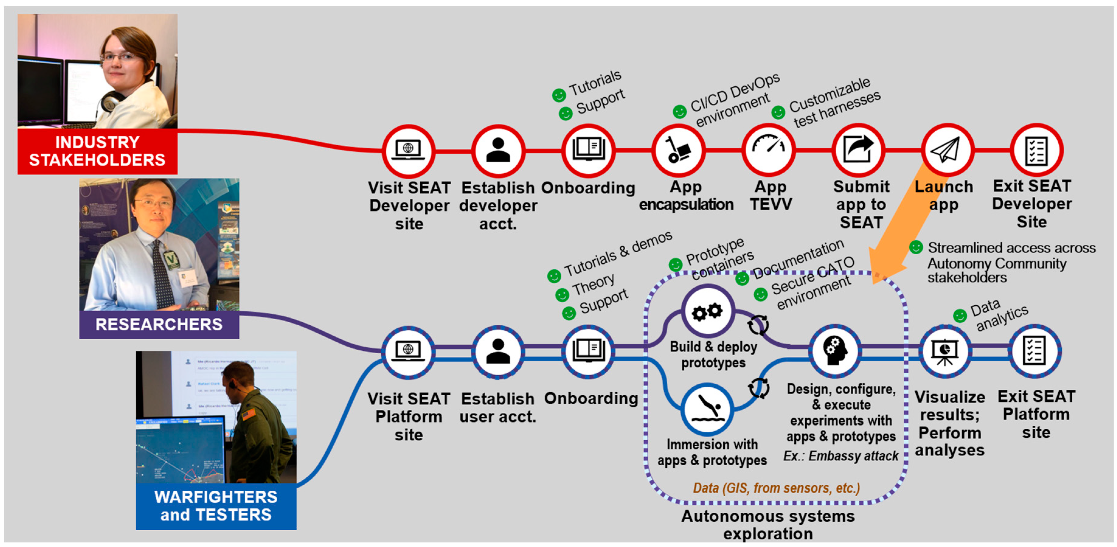
  • Warfighter/Test and Evaluation Assessor—A domain expert, evaluator, or end-user that may provide the model or the overall scenario context and is interested in all aspects of the modeled System of Systems (SoS) or may want to test out or experiment with a specific capability;
  • Researcher/Developer—A software/systems/simulation engineer that builds or contributes to the SEAT infrastructure and manages the release/build process through the CI/CD DevSecOps methodologies. This user engineers the M&S SoS federation;
  • Industry Stakeholder/Practitioner—An external participant who contributes to the SEAT framework in either a passive or active manner and brings modular capabilities for integration into the SEAT environment that are provided by the researcher/developer.
Figure 2 is a graphical depiction of the generalized workflow supported by the user types defined above each user type.

4.2. SEAT Layered Reference Architecture Framework

From this initial set of driving requirements, Journey-Mapping products, and conceptualization of various user workflows, the team constructed an initial formalized conceptual layered architectural framework, the SEAT Layered Architectural Framework (Figure 3), to guide the prototype and subsequent reference implementations as part of the exploratory and technical-risk reduction process.
This layered M&S reference architecture is built using formalized simulation and software engineering concepts to categorically separate the modeling and simulation layers. It also adds the vertical user app and security layers, indicating the user apps can serve any of the horizontal layers and that the security aspect must be handled at both horizontal and vertical levels in support of DR-3, DR-4, DR-5, and DR-6. The reference architecture supports driving requirements DR-1 and DR-2 by isolating both hardware and cloud platform services such that higher-level components and applications can be containerized and run on a variety of hardware and cloud platforms. Security, shown as a vertical bar, can serve across layers and supports DR-2.
Additionally, the layers are also categorized into end-user and automation aspects to emphasize the automation technologies that are available for simulation, cloud APIs, and infrastructure levels. The “End-user” layers are recognized to emphasize support for customized interfaces for the appropriate user roles as described in Section 4.1 and are in direct support of DR-3, DR-4, and DR-5. Many of the layers are marked “dockerized” to emphasize the use of container technology in those layers in support of DR-1 and DR-6. Although the entire SEAT framework intends to take advantage of advancing containerization technology, some visualization services may not lend themselves to containerization as they may require considerable graphical processing power. This is to be supported by semi-automated workflow engineering practices that need to be customized for every project and leverage integrated Development, Security, and Operations (DevSecOps) and on-demand deployment capabilities in support of DR-6.
Finally, the SEAT framework is offered as a service architecture in line with the MSaaS paradigm. It is also envisioned that all of the layers will be available within a service paradigm. Next, we describe these service layers.

4.3. SEAT Reference Service Layers

4.3.1. Hardware Infrastructure (IaaS)

The identification of the hardware infrastructure layer highlights the need to isolate applications from specific hardware dependencies and limit those dependencies as much as possible. This also accounts for specific requirements to support GPU or high-performance computing (HPC) hardware, and SEAT can interoperate with those applications; however, the focus is to use standards-based APIs for operating system interfaces to minimize the special cases. Applications integrated within the SEAT environment include both Linux- and Windows-based applications that run on commercial hardware. This layer is invoked from the layer above it (see Figure 3), namely the Cloud Platform layer, implemented as Platform-as-a-Service (PaaS). A MITRE product, namely MITRE Symphony™ [31,32,33], is used for IaaS functionality.

4.3.2. Cloud Platform (PaaS) Services

The Cloud Platform Services Layer identifies the need for executing on multiple cloud-vendor or hybrid cloud solutions and not locking into any one vendor’s cloud-based solution. This layer allows the utilization of IaaS and makes the hardware accessible in a transparent manner. More details are provided in Section 6.

4.3.3. Simulation Infrastructure as a Service (SIMaaS) and Software Utilities as a Service (SaaS) Reference Layer

Many of the fundamental distributed M&S system requirements are handled through the following two layers:
  • Simulation Infrastructure (SIMaaS): This component houses essential and common simulation tools offered as services that can be shared across the executing simulations. Examples of simulation tools that have been integrated as services include Unreal Engine, NetLogo (headless), Gazebo, and customized Command and Control simulation software. These common services include middleware message services such as EMQX, object brokering services such as the High-Level Architecture Runtime Infrastructure (HLA RTI), data transfer services through Distributed Interactive Simulation (DIS), time and event management services, database and repository services, and environmental representation services through project-specific middleware. Other specialized services include damage effects services, vulnerability modeling services, etc.;dsf
  • Software Utilities (SaaS): This component houses software libraries and utilities to support scenario creation, data harmonization, and both information and model validation, as well as an asset library for compilation and translation tools. SaaS supports both the SIMaaS and MaaS layers and interfaces with PaaS for deployment on Cloud infrastructure.

4.3.4. Modeling Services (MaaS) Layer Reference Implementation Layers

The MaaS layer describes the user-specific asset (e.g., a model, algorithm, or System Under Test (SUT)) and its utility and applicability as part of the Modeling layer. It handles the availability of models as services. Models are built using specific model design/editing workbenches and are written in either domain-specific languages (DSLs) or directly using programming languages such as C, C++, Java, C#, Python, Lisp, and many others. This layer provides the infrastructure to make models available for the simulation tools as described above in the SIMaaS layer. Figure 1 provides a layered structure where the fidelity and resolution of a model are considered. This layer further stores these models in a model repository for reuse. The MaaS layer leverages SIMaaS and SaaS to fulfill the function of model execution.

4.3.5. Experimentation and Gaming Services (EXaaS)

The next level in the SEAT layered framework is where experimentation services reside that invoke the Modeling Services layer to execute the model (by running a simulation through the SIMaaS layer). Tools to enable random-seed selection, replication configuration, and design point identification are found here, as are analytic tools such as Jupyter notebooks, Python, and Microsoft Excel.

4.3.6. Visualization Services (VISaaS)

The final layer, Visualization Services, is more of a logical partitioning than a separation of specific applications. This is because many of the legacy (non-microservice-oriented) applications provide their own visualization tools. Some provide a browser-based display that can be accessed when the application has been containerized, allowing for greater flexibility in deployment options. However, many applications have been developed with a model-view-controller paradigm that separates the client-side presentation, visualization, and control mechanisms via APIs from the server-side model software components. This aids in refactoring or providing additional separate containers for visualization tools.

4.3.7. Data/Repository Layer

This vertical layer interfaces with all the horizontal layers described above and provides the database backend for all the layers. This layer identifies the data standards, formats/syntax, and storage mechanisms for the whole project. For the PaaS layer, it stores hybrid cloud configurations as “SEAT-packs” that can be deployed at once. For the SIMaaS and SaaS layers, it stores various software/simulation tools that are eventually made available as service instances. This may include licensing servers as well. For the MaaS layer, this offers a model repository and associated data exchange requirements for a model. For the EXaaS layer, it offers various experiment configurations and data capture specifications to readily deploy an experiment. For the VISaaS, it offers storage of various visualization tools and associated licenses that can be leveraged by a project. The data/repository layer also interfaces with the analytics vertical layer to fulfill various analytics data needs.

4.3.8. Analytics Layer

This vertical layer interfaces with all the horizontal layers and provides instrumentation and analytics services to them. For PaaS, it provides instrumentation of cloud resource utilization. For the SIMaaS/SaaS layers, it provides instrumentation for simulation resource utilization. For the MaaS layer, it offers analytics services to instrument the fidelity/resolution tradeoff and utilization. Similarly, it supports EXaaS and VISaaS layers with appropriate analytics. It leverages the data/repository layer to store instrumentation data.

4.3.9. User App Layer

This layer is made vertical for one simple reason: a user (Figure 2), especially an industry stakeholder/practitioner, can develop an app/service that may interface with any of the horizontal or vertical layers to support an ongoing project. This is the prime feature of the SEAT layered framework, wherein external user apps can be brought into an existing project in a modular manner using service facades.

4.3.10. Security Layer

This vertical layer corresponds to various security features that need to be implemented to secure tools, services, physical assets, and various other project artifacts. The security layer can further be organized into various layers, and there are efforts underway to implement Multi-Level Security (MLS) approaches for distributed LVC architectures. Presently, we are dealing with Unclassified/Controlled Unclassified Information (CUI) infrastructure. The case study described in Section 8 is CUI-compliant, as are the incorporated M&S and AI-enabled tools.

5. SEAT Engineering Methodology

For any scalable simulation and experimentation environment, one must consider the extreme case of a distributed application with federated simulators. Consequently, the SIMaaS and SaaS layers incorporate toolsets that facilitate engineering a distributed simulation environment. In any distributed simulation integration within a digital engineering endeavor, the following factors must be addressed:
  • Selection of appropriate SEAT architecture layers: Every SEAT-compliant project and the associated SoS architecture will be different in terms of the different tools and services that need to be brought together for a specific project (Figure 4);
  • Unified data model: Having a common data model is a fundamental requirement for integrating two different systems that need to interoperate;
  • Transport mechanism between constituent systems: This includes the communication protocols and the actual physical channels for message exchange;
  • Hardware/Software interfaces are implemented through Application Programming Interfaces (APIs). This includes various APIs wrapping the hardware/software components;
  • Deployment of the software components over the hardware and Cloud infrastructure: If the software is modular, this aspect provides external APIs for access and control, and if it is platform-neutral, then it may be containerized and made available as a container within the Docker paradigm;
  • Dependency management for the constituent systems. This includes various software libraries and execution environments that need to be bundled for a certain component;
  • Time and event synchronization: This is a critical aspect of any distributed simulation integration. The software systems may have time and event dependencies;
  • Information, message, and object brokering. This includes various message brokers for enabling information/data exchange;
  • Existing Continuous Integration/Continuous Delivery (CI/CD) mechanisms. This includes various CI/CD pipelines that each of the software components brings;
  • Rapid and Continuous Authority to Operate (rATO, cATO): The objective is to have a SEAT environment where new or modified applications can be rapidly approved and incorporated into the simulation environment through a process that supports a Continuous Authority-to-Operate (Continuous ATO or cATO). There are two primary objectives for information assurance: rapid ATO and application approval and security. Rapid ATO is a process by which applications can receive an ATO quickly. Application approval and security provide a mechanism to integrate applications with minimal delay and without jeopardizing security objectives.
For Information Assurance (IA) analysis, the SEAT framework can be viewed as a three-tiered system (Figure 5) composed of:
  • An operational SEAT Development runtime environment that runs the simulations with interoperating models (for Warfighter/Tester);
  • An infrastructure development CI/CD pipeline (for Researcher/Provider);
  • An application development CI/CD pipeline (for Industry/Vendor).
The infrastructure and policies that require CI/CD pipeline approval are relatively static, so the timeline to acquire the ATO as compared to the application software, which changes much more frequently, can be significantly reduced. Containerized servers instantiated by an approved CI/CD pipeline can help develop compliant infrastructure quickly. Achieving a cATO requires clearing a high bar [34]. The key requirements are Continuous Monitoring (CONMON), Active Cyber Defense, and a Secure Software Supply Chain. A full cATO system is beyond the scope of SEAT; however, SEAT has been designed to fit into a larger system that has achieved cATO. SEAT does not have a CONMON solution of its own but has configuration options that facilitate various types of CONMON scanning. The underlying MITRE SymphonyTM platform (see Section 6) providing the Infrastructure-as-Code (IaC) implementation is hardened at the network, application, database, and OS layers.

6. Cloud-Based Infrastructure

Many projects need to engage in infrastructure experimentation, design, creation, redesign, hardening, deployment, and transition in addition to the actual R&D goals of the project. These projects are often staffed with an eye towards the project goals as opposed to the “solved” problem of infrastructure. While this affords learning opportunities for staff in infrastructure development, it is also a large drain on project resources. At an organizational level, this results in a lot of duplicated effort as every project reinvents the infrastructure wheel to suit their needs. It also hinders deployment and technology transfer, as every project requires the sponsor to learn all about the underlying infrastructure in addition to the actual system itself. Sponsors’ environments often house many different systems, and frequently, the new project needs to be modified to fit into their environment. A successful deployment typically involves lengthy security assessments and remediation, replacement of ad hoc monitoring and authentication systems with enterprise integrations, etc. Deploying on cloud-enabled infrastructure adds additional complexity due to elements of elastic resource provisioning, scheduling, etc., and a framework such as SEAT allows semi-automating the deployment of an operational virtual, constructive component architecture on to a cloud-enabled infrastructure.
Cloud resource provisioning is an integral part of the SEAT Project’s execution. The SaaS, PaaS, IaaS, Data/Repository, and Security SEAT layers (Figure 3) are utilized in this exercise. Each SEAT Project is provisioned with an isolated enclave that includes dedicated cloud computing resources. We leverage the MITRE Symphony™ platform to automate this provisioning process. This automation supports various ATO mechanisms, such as cATO or rATO. As this provisioning process is designed for extensibility, we exercised that capability to develop various SEAT packs, which are modular configurations of SEAT components that can be utilized as canned configurations in the overall project and can be pieced together in a composable manner.
Accrediting a system is a lengthy and intensive process. It involves considerable overhead that is often not justified until a sponsor has shown real interest in bringing a project into production. Many software engineers are unfamiliar with the accreditation process and the requirements that may come into play when deploying a system for a sponsor. It is also very burdensome for the sponsor, who must learn the design and security systems of every new project from scratch and evaluate each one in turn. A standardized foundation for systems eases the burden on both the development team and security assessors. The development team has a clear view of an approved architecture that can guide early decisions to minimize later rework to meet security standards. The assessors can avoid reassessing the portions of a system that are standardized (often supporting infrastructure like perimeter firewalls or OS logging) and instead focus on the unique components of each system.

6.1. MITRE Symphony Platform

MITRE’s Symphony Platform [31,32,33] is a system for deploying computing enclaves into the cloud via IaC. Roughly, it can be seen as a big installation script that, when run against an empty cloud platform (e.g., an Amazon Web Service (AWS) account) it automatically produces a secure computing enclave with centralized IdAM (Identity and Access Management), centralized logging, firewalls, virtual desktops, and customizable additional tools. The initial deployment creates a working Linux environment that is secure out-of-the-box and ready to host the R&D effort. This lets the team get to work more quickly on the actual project. A key feature of Symphony is the Pack API, which lets a project customize their enclave with virtual machines (VMs), subnets, firewall rules, software, and cloud computing constructs. This encourages the team to automate their own software deployment, which makes future tech transitions much easier. It also lets the project reuse the packs created by other teams as building blocks for their own system.
Symphony’s standardized IaC design provides such a foundation. Symphony enclave deployments are repeatable and automated, so the generated system is consistent. This gives confidence to the AO that two different Symphony enclaves created by the same version of Symphony with the same input configuration will be functionally identical. Then, instead of accrediting a single Symphony enclave, the AO can accredit the Symphony platform itself. Any enclaves generated by the Symphony platform in the approved configurations do not need to obtain their own ATO. If a new enclave needs to modify the baseline by adding a new application server, for example, then the ATO process is much shorter because only the differences between the new enclave and the baseline need to be assessed and authorized.
Symphony’s IaC design also facilitates the automated build and deployment of Symphony enclaves. An automated build pipeline is a key component of DevSecOps, which is a requirement for continuous Authority to Operate (cATO). cATO represents the “gold standard” for cyber security in the DoD and is a target to strive for.
As the project matures, Symphony’s automated deployment lets the team easily maintain one stable enclave for demos and user testing and a separate dev enclave for experiments and further development, in alignment with Figure 6. These automated deployments also prepare the system for transition to the sponsor. Symphony offers an adjustable range of security controls and firewalls that allow the project to tailor an enclave to meet a sponsor’s security requirements. Automated deployments let the project rapidly test their system in different security postures without breaking the existing development and test enclaves.
At transition time, Symphony’s Platform Abstraction Layer helps integrate the project into a sponsor’s environment. It lets the team customize lower-level aspects of the enclave to fit nicely into a sponsor’s network. It can be used to change network layouts, customize base VM images, integrate with existing IdAM systems, and switch cloud environments.

6.2. Infrastructure-as-Code (IaC)

Symphony is primarily implemented in Terraform and Ansible (Symphony 2022a,b). Terraform is an IaC tool that provisions and configures virtual and physical infrastructure in a declarative manner. It has support for many different cloud platforms as well as some hardware. Terraform employs a domain-specific language to define the resources to provision.
Ansible is a configuration management tool that configures the Operating System (OS) and installs software on various Virtual Machines (VMs) that comprise a Symphony enclave. Ansible is a lightweight tool that does not require a centralized server. It uses an “agentless” design that employs SSH as a control channel and only requires Python to be installed on remote nodes that it manages. The base unit of execution in Ansible is the task. Tasks are usually bundled together into roles. Plays are collections of roles and tasks that target a specific set of hosts. Playbooks are a series of plays. The SoS configuration is represented through these playbooks.

6.3. Hybrid Cloud Deployment

Some environments are hybrid clouds that involve multiple hosting platforms. Symphony’s Provider API can support a hybrid cloud as easily as a single cloud, but some minor changes to the core of Symphony and the Pack API were necessary to make it easy to configure an enclave regardless of the chosen cloud environment. A key design goal was to minimize the changes to a pack for it to be used in a hybrid environment. The strategy chosen was to map the network zones in an enclave to different clouds. This configuration occurs outside of the pack manifests and the providers themselves, so that the layout of the enclave can be adjusted without modifying any of the mission packs or providers. Each network zone is assigned to a cloud. All VMs are assigned to a network zone. Symphony’s Pack API required some adjustments to make hybrid deployments more user-friendly. The API itself was refined to be less AWS-centric and to support VM and network customization by cloud type.

7. MSaaS Workflow Engineering

This chapter describes the architecture for workflow engineering for MaaS and SIMaaS layers.

7.1. Workflow Engineering for M&S

As we are dealing with heterogeneous architectures, not all software can be containerized. Some are commercial tools that need an entire Virtual Machine. Each type of tool will need to be either packaged as an executable that is controllable via a command-line script using languages like Perl or Python, or the tools must be masked behind a service façade with a specific functional interface that allows other applications to exchange data with the tool. The workflow engineering aspect of this framework is to understand the tool’s external capabilities and interfaces and guide their development towards semi-automated service façade development.
The workflow engineering is divided into two phases, described below:
  • Onboarding and provisioning;
  • Software and simulation integration.

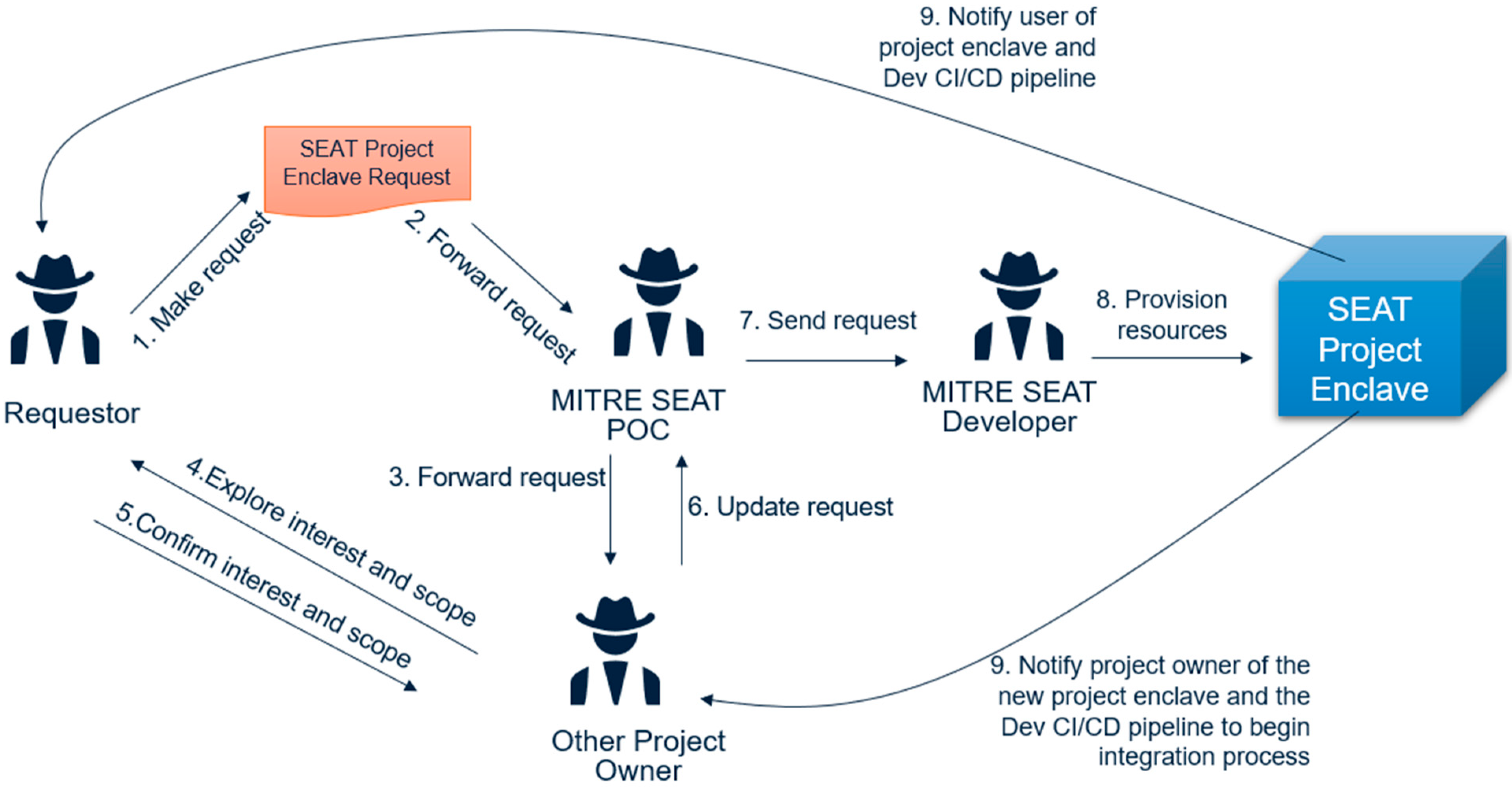
7.1.1. Onboarding and Provisioning Workflows

This workflow (Figure 7) sets up a SEAT Project enclave for two types of users and is executed as such.
  • Provider Workflow: This workflow is executed by a Researcher (Figure 2) user class. This user (Other Project Owner in Figure 7) provides Simulator/SDK, which offers the M&S project’s backbone and the associated data communication and simulation infrastructure;
  • Model/System Workflow: This workflow is executed by an Industry Practitioner (Figure 2). This user (the Requestor in Figure 7) contributes a model/algorithm that is to be integrated with an existing simulator or project;
  • Experimentation Workflow: This workflow is executed by the Warfighter or T&E practitioner (Figure 2). This user exercises the integrated solution developed by the other two user types for large-scale concurrent experimentation.

7.1.2. Software and Simulation Integration Workflow

This workflow assumes a project enclave, and its objective is to align the data models between the provider and model/algorithm. It unifies and harmonizes the data model. There are two modes for this integration:
  • Passive (read) mode for data listening only: The incoming model/algorithm application, or “app”, will passively listen to the data channels for accessing data/repositories to add value through its app. It may work with or without simulation integration and may provide value addition both during simulation and post-simulation;
  • Active (read/write) mode for simulation integration: The incoming application, or “app”, requires comprehensive integration with simulation engines. The level of effort is dependent on a case-by-case basis. Various available simulation interoperability standards, such as DIS, HLA, or Test and Training Enabling Architecture (TENA), could be used to align the data models and implement time synchronization strategies.
While the onboarding and provision workflows are semi-automated, the integration workflows can be automated once the integration touchpoints have been defined. A methodology is described in the section ahead.

8. Case Study

This section will describe a case study that:
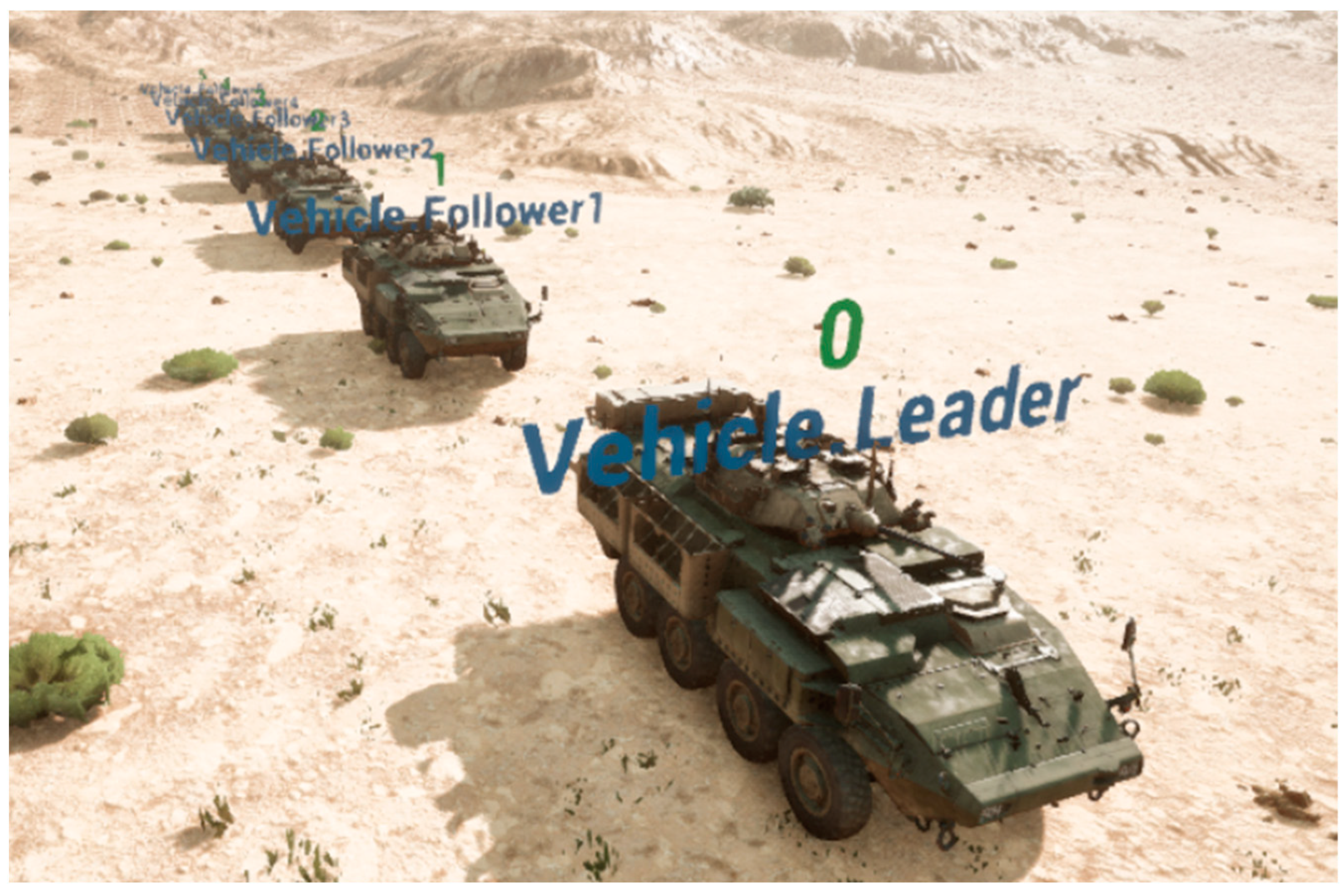
  • Models Expedient Leader Follower (ExLF) using unmanned ground vehicles (UGVs) in a high-fidelity, high-resolution environment within a broader mission context;
  • Applies MSaaS and the SEAT framework to engineer the M&S architecture;
  • Offers the entire augmented architecture as an on-demand test architecture deployable in a cloud environment.

8.1. Scenario Description

We developed a scenario to evaluate the utility of UAVs to support ground forces in a mission-focused breach scenario. The ground forces include a UGV convoy that has leader-follower behaviors, allowing us to start the convoy by directing the commands to the leader only. The convoy has 6 UGV vehicles, including the leader vehicle. The commands include orders like stop, move, deploy, etc. The breach scenario has an established red force that blue is trying to breach through. It is setup around a traffic circle, with the blue’s mission being to overcome the red forces around the traffic circle. There are some red elements that are on the forward side of this force to provide jamming and ISR for the red. The blue forces will initially take them out. The blue UGV convoy will engage in interactions with these forward red elements to reveal their position through sensing and fires. This information is relayed back to the blue command center through a network of communication links established between the blue UAVs and UGVs. The UGV convoy further represents a supply-chain convoy that is delivering supplies to forward positions. Their role is dual: delivering supplies and drawing fire from the red forces to reveal their position and, in turn, protect and help guide convoy trajectory (in an expedient leader-follower manner). As the convoy moves up in the traffic circle area, they will be identified and engaged by the red, and although the blue strategy does want them to draw enemy fire, the strategy does not want to sacrifice the entire convoy, so stop orders will be issued once the enemy locations have been revealed after sacrificing a maximum of three follower UGV units. This will lead to stopping the remaining convoy in its tracks and preserving their supplies.
This scenario is designed to accomplish the following objectives:
  • Demonstrate modeling of UGV expedient leader-follower behaviors at high fidelity and resolution using gaming engines such as Unreal Engine;
  • Integrated a convoy pattern in a larger mission context using high-fidelity and low-resolution models;
  • Demonstrate an integrated multi-fidelity simulation architecture;
  • Demonstrate MaaS and SimaaS as separate capabilities;
  • Demonstrate the deployment of the entire M&S architecture in an on-demand manner in a target cloud environment.

8.2. Application of SEAT Engineering Methodology

Section 5 described a 10-step methodology for implementing a SEAT-guided solution. Let us elaborate on each of the factors as they are addressed in implementing the scenario described above.
  • Selection of appropriate SEAT architecture layers: To implement the scenario, we will be working with the MaaS, SIMaaS, SaaS, PaaS, IaaS, User App, Security, and VISaaS layers from the SEAT layered architecture framework (Figure 3). Table 1 associates the layers with the different tools brought together;
  • Unified data model: Google Protocol buffers [35] as our data specification format. The data bindings can be generated in languages such as C++, C#, Dart, Go, Java, and Python;
3.
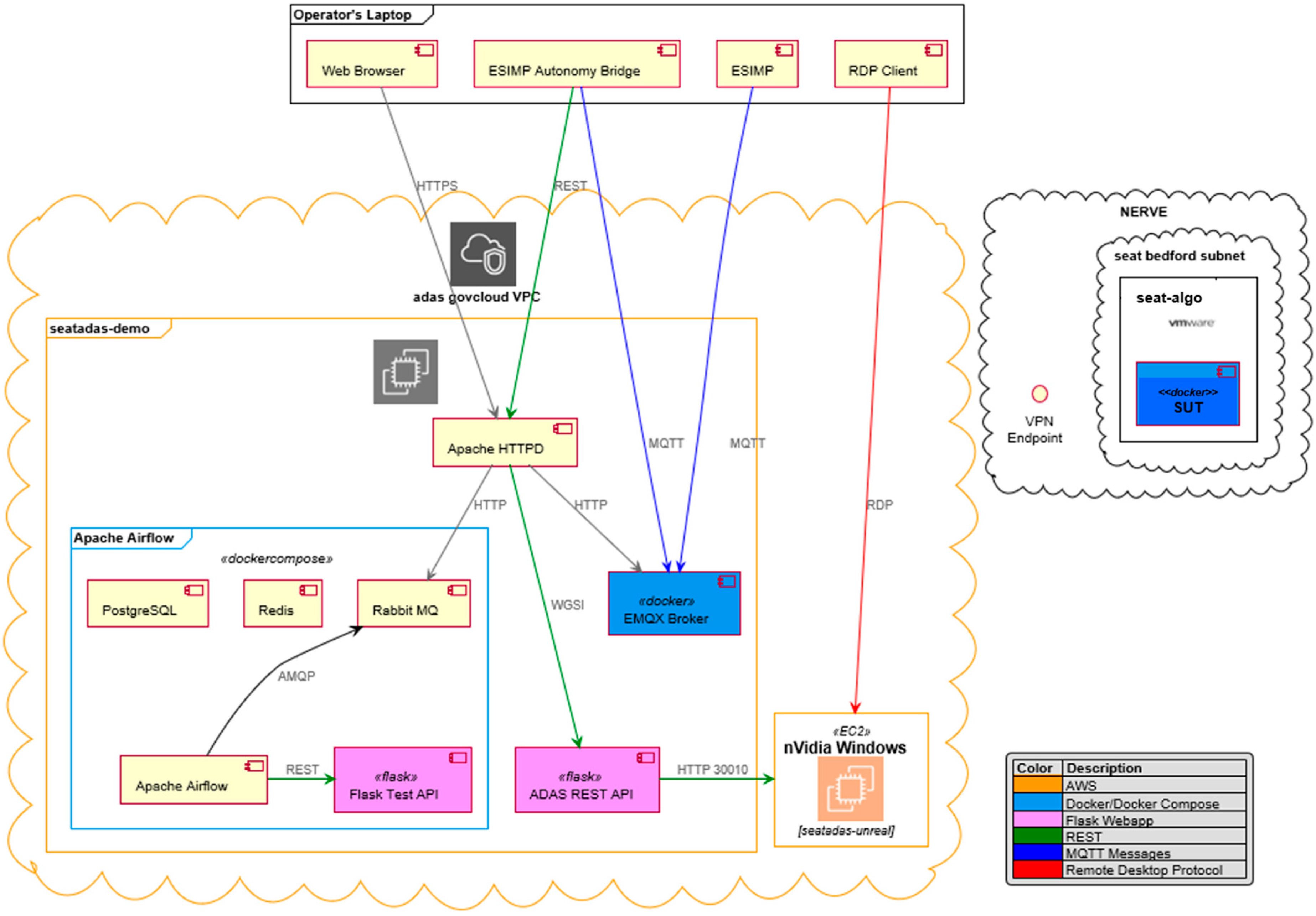
Transport mechanism between constituent systems: The EMQX (2020) message broker and the MQTT (2020) communication protocol that runs on TCP/IP between the simulation participants (ESimP and Unreal). The EMQX broker is a fully open source (Apache License Version 2.0), highly scalable, highly available distributed MQTT messaging broker for the Internet of Things (IoT), Machine-to-Machine (M2M), and mobile applications that can handle tens of millions of concurrent clients. EMQX supports MQTT V5.0 protocol specifications [36,37] as well as other communications protocols such as MQTT-SN, CoAP, LwM2M, WebSocket, and STOMP.
We also used REST HTTP protocol at the service façade layer to connect the command and control (C2) layers, User App and workflow execution;
4.
Hardware/Software interfaces: The Unreal and ESimP M&S systems through the Protocol Buffers interface with the EMQX message broker. EMQX provides various bindings and adapters to interface with the two systems;
5.
Deployment of the software components over the hardware:
  • EMQX, ESimP, Flask, and Apache Airflow [38] are deployable on Windows, Linux, and MacOS platforms or as a docker image for cloud deployment;
  • Unreal is deployable on Windows platforms within a VM. A plugin called Remote Web Interface was used to develop the service façade in Unreal;
6.
Dependency management for the constituent systems: EMQX requires the Erlang OTP runtime environment. ESimP is built on NetLogo and requires Python binding. Unreal requires specific network configuration for remote visualization. Flask and Workflow engines require Python runtime;
7.
Time synchronization: We adhere to real-time integration, so both Unreal and ESimP advance in real-time. All the propagation delays are negligible as both systems will be within the same enclave;
8.
Information, message, and object brokering: EMQX and RabbitMQ were used as information brokers. EMQX was used to integrate ESimP and Unreal. RabbitMQ was used in building customized workflow execution;
9.
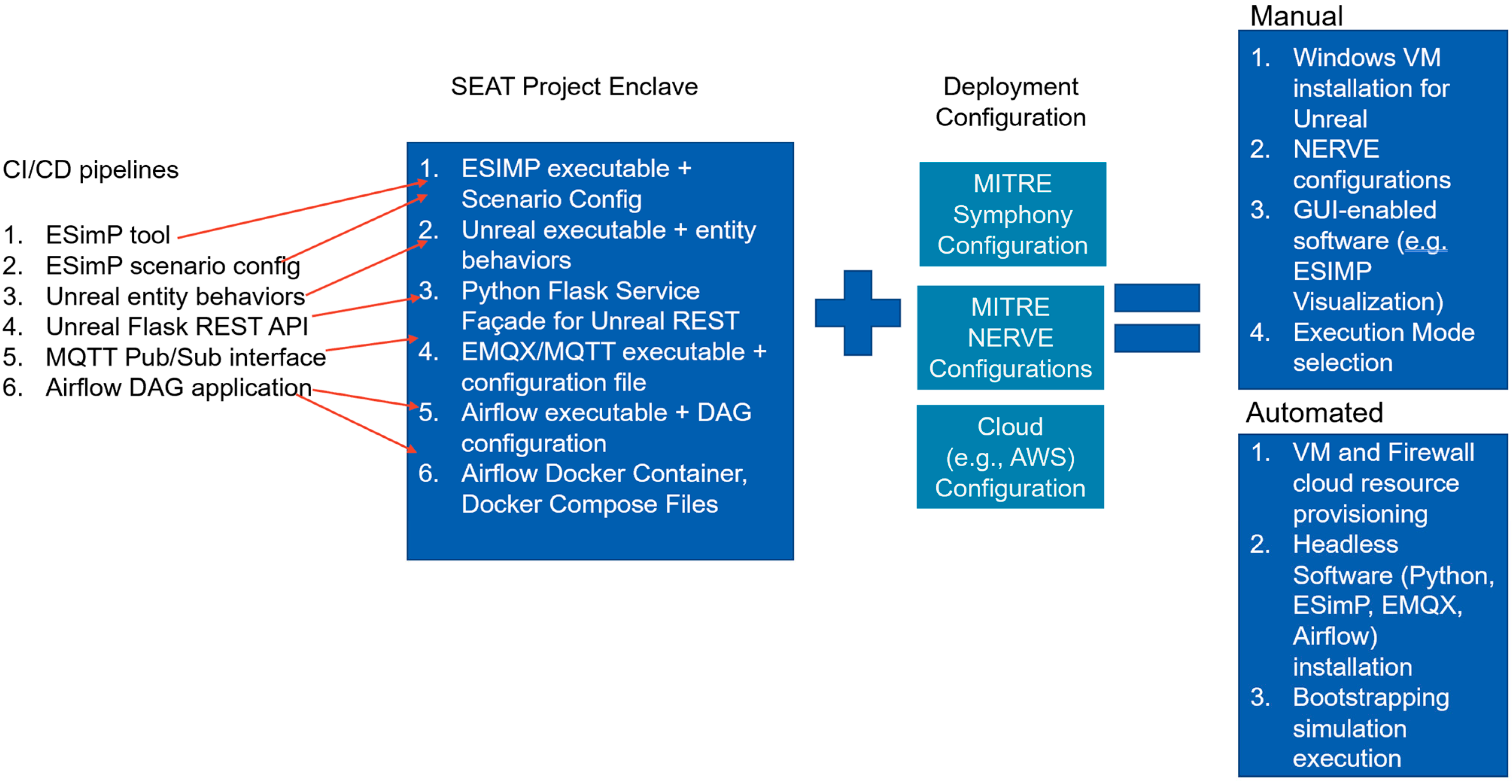
Existing Continuous Integration/Continuous Delivery (CI/CD) mechanisms: The project had multiple software modules that contributed to the solution. Figure 8 shows various CI/CD pipelines that must be brought together to build the entire M&S architecture solution;
10.
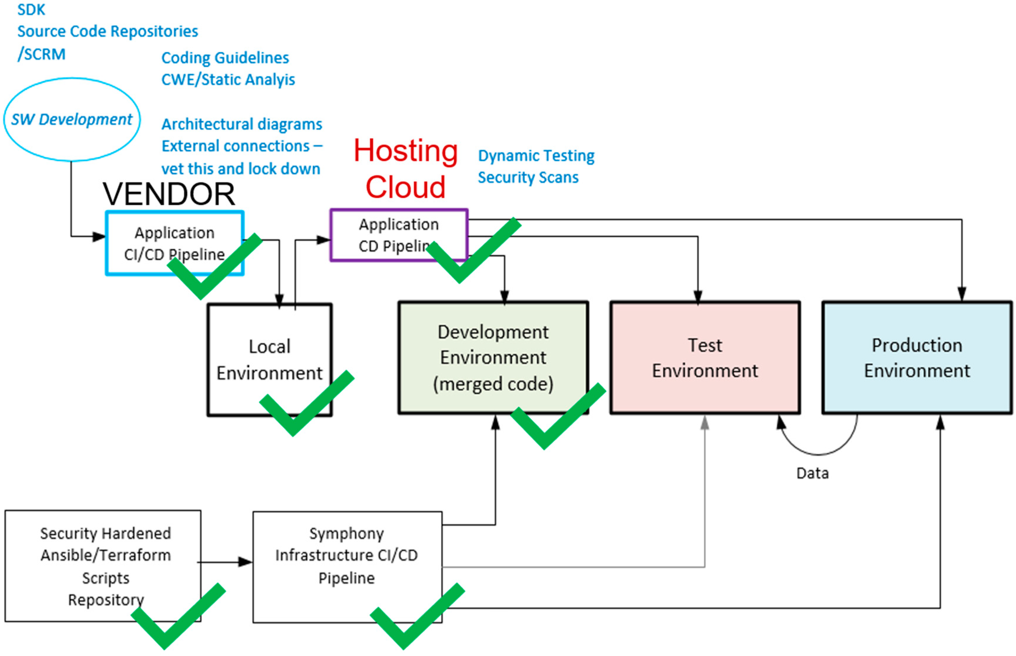
Rapid and Continuous Authority to Operate (r-ATO, c-ATO): As stated earlier, for the purpose of an IA analysis, the SEAT framework can be viewed as a three-tiered system (Figure 5). The operational SEAT environment is the Development Environment Enclave. The infrastructure and application CI/CD pipelines are to be brought together to integrate the modeling and simulation tools and applications in the Development Environment. This entire configuration set, along with the deployment configuration, can be subjected to cATO and rATO processes. Figure 8 shows the various CI/CD pipelines and configurations that support semi-automated deployment. Once the Development Environment Enclave is operational and the scenario is executable as an integrated architecture with ESimP and Unreal, the entire solution architecture is ready for on-demand deployment as a test environment (Figure 5) enclave using the IaC. The green checkmarks in Figure 5 reflect the state of maturity of the semi-automated process.

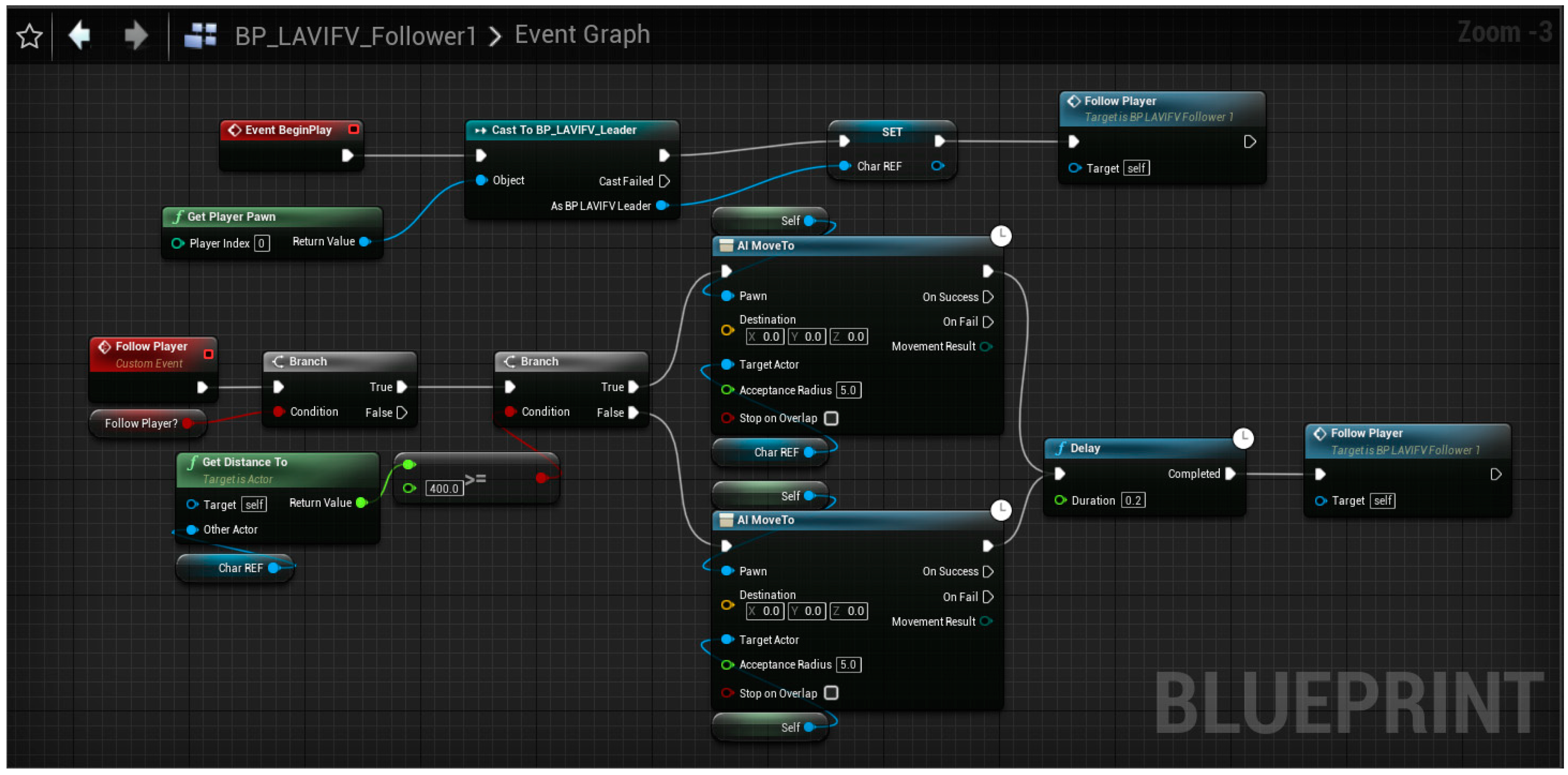
8.3. ESimP and NetLogo Mission-Level Modeling Environment

ESimP was initially developed in early 2019 as part of the MITRE internally funded small-robot capstone effort to provide a simulation environment to explore unmanned system capability trade-space within a limited, mission-focused “breaching operation”. For this project, in addition to traditional kinetic and maneuver warfare, the simulation environment was required to support representations detailing the impact of capabilities across contested spectrum use, manned and unmanned (tele-operated, semi-autonomous, and autonomous) system engagements, and fighting against a competitive and well-armed adversary. The simulation environment had to allow agile and quick model and simulation development and refinement; be easy to use and run; and not require significant overhead to obtain, setup, run, and analyze results.
To meet original timelines and small-robot capstone study requirements ESimP was developed as an extensible simulation platform using Netlogo. NetLogo is a free open-source multi-agent-based simulation infrastructure [39]. The initial investment in this simulation environment has produced a working multi-resolution combat simulation highlighting the impact of networked capabilities on mission impact where autonomous, semi-autonomous, and completely teleoperated systems carrying a variety of sensors, weapons (kinetic and non-kinetic), and radio devices can be explored within a visual environment or run as a closed-form analytical environment. The ESimP combat simulation allows the simulation developer and analyst to focus on and assess complex system interactions, dependencies, and contributions to higher-level mission outcomes. ESimP is now growing as an extensible simulation-based environment supporting a variety of experimentation possibilities, from human-in-the-loop “what if” type concept exploration to fully autonomous with artificial intelligence (AI) driving agents exploring emergent behavior space for competitive advantages. It is also being used to provide a mission-focused simulation to explore third-party decision-support tools.

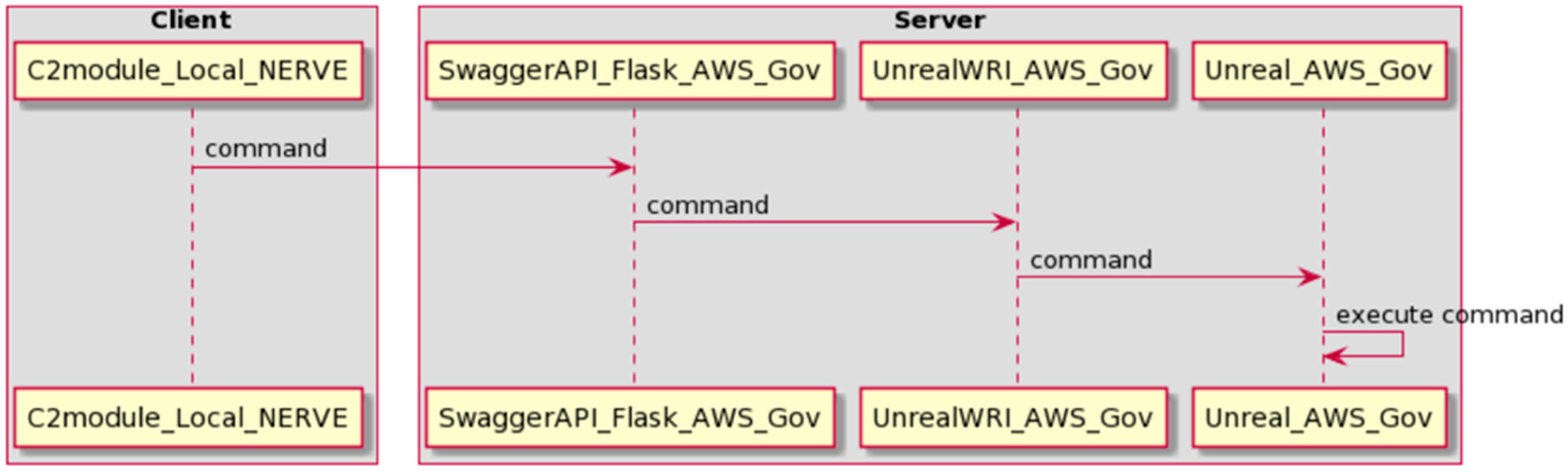
8.4. Unreal Engine and Modeling as a Service (MaaS) API Design

This case study explored the use of the Unreal Engine for creating a high-fidelity/high-resolution simulation that allows for external C2 using a layered services approach (Section 4) in a cloud-based environment using REST APIs. Externalizing the C2 is analogous to separating the brain from the body. In our case, separation is mediated by a set of layered services through REST APIs. The Unreal implementation includes a six-vehicle UGV convoy with basic leader-follower behaviors defined (Figure 9).
A library of custom functions was developed in Unreal using the Blueprint system that allows the user to perform a variety of commands, such as moving the leader vehicle or retrieving information such as speed and heading for the vehicles, through customized service functions. This library of functions is externally exposed using the Unreal Web Remote Control API plugin, which sets up an internal web server and REST service within Unreal and allows the ability to call the user-defined functions. A second REST service was created using Python and Flask that provides a more user-friendly set of endpoints as well as the ability to define higher-level functions outside of the game logic. This REST service calls into the Unreal REST service and provides the structure needed to allow external systems to send C2 instructions to the Unreal simulation. This capability can be used for a variety of mission-level assessments, such as testing the resiliency of a convoy or testing vehicle swarming behaviors.

API Architecture

The API architecture developed for this capability is designed in a layered fashion, where one REST service calls the other. The first layer of the REST service is what the user interacts with directly. This is the Command and Coordination Behavior Service API Layer (MaaS depiction in Figure 1). It is implemented as a Python Flask application deployed on an AWS GovCloud machine (Figure 10). This REST service defines higher-level behaviors that the user can invoke to issue a variety of commands that are sent into the Unreal simulation. These include behaviors such as having the leader vehicle perform a patterned movement such as a box or circle pattern. The logic for calculating the waypoints in the movement patterns is defined within the REST service as opposed to in the Unreal simulation. This decoupling of the vehicle logic from the simulation provides an example of how the capability can be expanded by defining new behaviors within the first-layer REST service without having to change anything within the simulation itself.
The Complex and Primitive Behavior Service API layers (Figure 1). These two layers are implemented as REST APIs within the Unreal simulation and are created by enabling the Unreal Web Remote Control API plugin. The main use of the Coordination Behavior Service REST API is to call custom functions defined within the Unreal Blueprint system (Figure 11) or C++ scripts through these two lower-level APIs. A library of functions was developed within Unreal and exposed via this method. These functions include behaviors such as moving the leader’s vehicle, destroying a vehicle, assigning leader/follower roles, and retrieving values such as speed, heading, and location. Table 2 describes the API definitions.

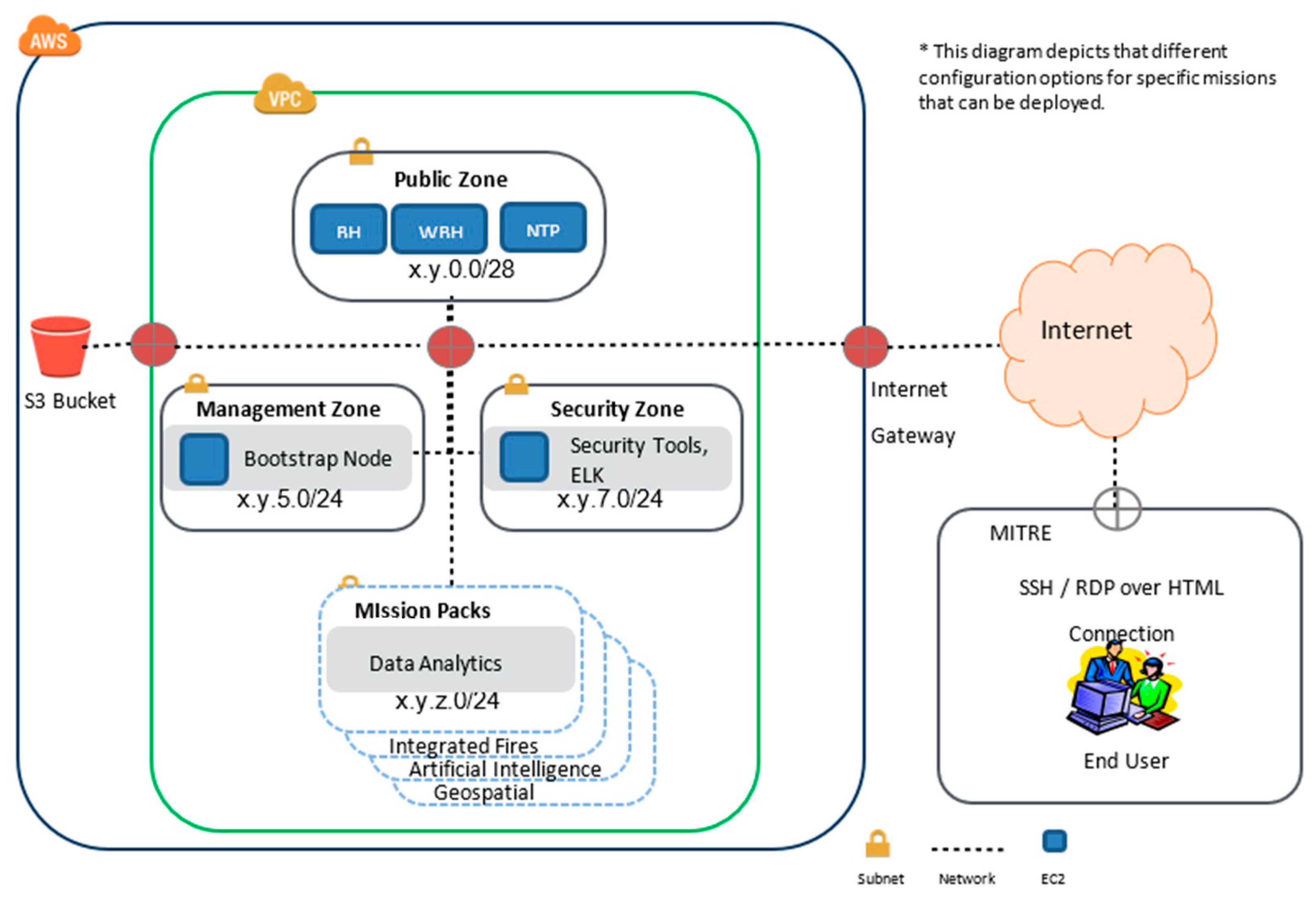
8.5. Cloud Deployment Architectures

The base system consists of two VMs:
  • seatadas-demo: Running Linux to handle EMQX, the REST APIs, and Apache Airflow;
  • seatadas-unreal: Running Windows to host Unreal.
The system deployment was semiautomated (Figure 8). The MITRE XCloud Team provisioned the base AWS environment automatically using a mixture of AWS CloudFormation and Python. Our team provisioned the AWS firewalls and seatadas-demo automatically with the Symphony platform. Our team manually provisioned seatadas-unreal. Most of the installation and configuration of the software on seatadas-demo was handled by Symphony and NERVE’s own Chef-based configuration management system. The REST API was hosted directly on seatadas-demo because of existing Symphony automation for hosting Python web applications with the Universal Web Server Gateway Interface (uWSGI) and reverse proxies. The project team wrote additional Ansible roles in the Symphony platform for the automated deployment of the standard EMQX Docker container. Apache Airflow and the related workflow components were deployed manually on the server via Docker Compose. The overall hybrid cloud-enabled architecture utilizing AWS GovCloud, NERVE, and a local laptop is shown in Figure 12. It also shows a fictitious SUT enclave that is accessible through a VPN within the NERVE environment.

8.6. On-Demand Deployment for a Test Environment

Although the deployment was successful (Figure 13), it still involved a fair amount of manual installation and configuration of tools. The REST API on seatadas-demo is now automatically installed and configured. The ESimP Autonomy Bridge middleware was migrated from the operator’s laptop to seatadas-demo as well and configured to run as a persistent service. The NERVE team granted our team permission to provision VMware VMs, and the Leader/Follower pack was updated to the new API to take advantage of Symphony’s new hybrid cloud support. The next steps include automated configuration of the Apache Airflow components and seat-mimic deployment. Provisioning and configuration of seatadas-unreal are possible but require enough effort that the sponsor would need to prioritize that feature.
This effectively demonstrates that an on-demand, semi-automatic deployment of Development Environment M&S infrastructure can be extended to test and production environments (Figure 8). To make such a deployment useful to other teams (and partners), the next step is to work with a sponsor to explore desired extension or customization points of the system. That will be explored in future work.

9. Discussion

We further investigated Platform One as a potential target cloud environment for hosting SEAT development and test enclaves, including a review of the services and policies associated with deploying capabilities on Platform One. To securely deploy environments on Platform One, a 12-factor application development process must be followed:
  • Codebase: A single application codebase tracked with a verified revision control system allowing for managed deployments;
  • Dependencies: Explicit declaration, isolation, and management of dependencies;
  • Configuration: Explicit storage of configuration information and data in the environment;
  • Backing Services: The treatment of backing services as attached resources;
  • Build, release, and run: Strict separation of build and run stages;
  • Processes: The application should be executed as one or more stateless processes;
  • Port binding: Export services via port binding;
  • Concurrency: Scale out via the process model;
  • Disposability: Maximize robustness with fast startup and graceful shutdown;
  • Dev/prod parity: Keep development, staging, and production as similar as possible;
  • Logs: Treat logs as event streams;
  • Admin processes: Run admin/management tasks as one-off processes.
The Platform ONE 12-step process is largely for software-oriented systems engineering. However, digital engineering for SoS engineering requires bringing several domains together, viz., model-based engineering, simulation engineering, M&S-based T&E, and integration with other domain-specific engineering tools for contextual and domain-dependent analyses.
The SEAT methodology is API-oriented and incorporates integrated workflows to manage synchronous and asynchronous data exchanges. While the focus of earlier approaches, viz., DIS-based is data-oriented, HLA- and TENA-based are API-oriented (for engineers), the focus of the SEAT-based approach is on business services as applicable to the end-user (through the considered Journey-Maps).

10. Conclusions

MSaaS requires specific architectural constructs, especially when developing hybrid architectures that include autonomous and AI-enabled components and an API-first paradigm. These architectures need to leverage modularity and API-first principles for the packaging required to integrate the latest software engineering and cloud computing technologies, such as DevSecOps, CI/CD pipelines, workflow engineering, and on-demand deployment. The SEAT layered architecture framework facilitates the development and deployment of M&S-enabled architectures and a shared data model in hybrid cloud environments. Having an on-demand M&S-enabled cloud environment with the latest DevSecOps practices and customized workflows allows large-scale experimentation for multi-domain use cases.
The MITRE Symphony Platform offers an on-demand hybrid cloud configuration capability that can be semi-automated to rapidly stand up an entire M&S SoS architecture in a cloud environment. The IaC capability expedites the cATO and rATO processes, bringing tractability and quicker approval cycles. These capabilities can be aligned with various Role-Based Access Control policies for different types of users, especially warfighter/tester, industry practitioner, or researcher users. The modular configuration aids resource provisioning and capacity planning for different target cloud hosting requirements, such as NERVE, AWS, PlatformONE, or CloudONE [7].
This effort has made the following contributions:
  • M&S services are implemented through a layered approach supported by a reference architecture (SEAT layered architecture framework);
  • Modular architecture was deployed in a cloud SEAT enclave using MITRE Symphony IaC and IaaS, reproducible to other target cloud infrastructures as well;
  • The heterogeneous architecture includes a federated M&S architecture using MaaS and MSaaS principles;
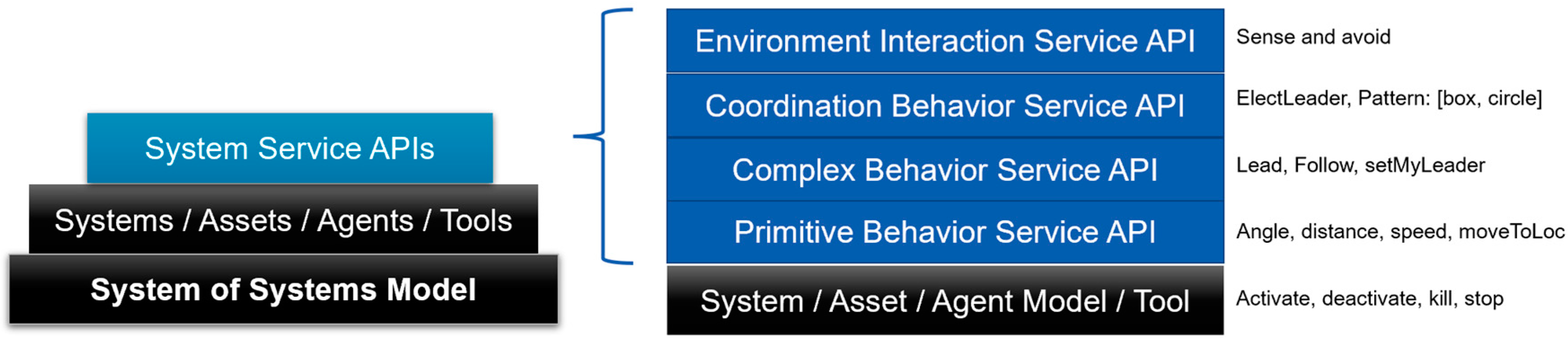
  • A modular autonomy controller can be replaced by a more advanced controller for experimentation with other leader-follower formations, leveraging entity-level behavioral APIs for a multi-fidelity experimentation environment;
  • The entire M&S architecture is made available on-demand and cloud-ready using MSaaS principles for extensibility, continued development, and large-scale T&E;
  • The workflow engineering infrastructure allows expedited development of service facades on various tools to be made available as tools-as-a-service within the layered multi-fidelity architecture for API-enabled SoS;
  • The development workflow with associated CI/CD pipelines and various tools as services can be deployed in a semi-automated manner in hybrid cloud settings;
  • The 10-step methodology can be reproduced for other M&S and AI-enabled integrated architectures with a rapid turnaround.
Having demonstrated the complete workflow engineering pipeline for “as-a-Service” for the ExLF multi-fidelity M&S test bench use case, we shall extend the methodology to demonstrate it in a more specific SoS T&E use case.

Future Work

The current effort brought together a mission-level high-fidelity, low-resolution model with a detailed UGV ExLF high-fidelity, high-resolution model. Efforts are underway to: (1) incorporate AI/ML components that can learn ExLF behaviors from this virtual environment and inject them in a “test” entity that is dynamically injected in the ExLF convoy; (2) incorporate various existing software-in-the-loop capabilities that offer services such as the Radio Frequency (RF) communication network model in a contested environment to support MDO experimentation; and (3) incorporate an API-agnostic data layer that separates the MaaS API with the data elements and includes adapters to transform data exchange between Protobuf, Test Enabling and Network Architecture (TENA)-objects and DIS/HLA data structures.
From the SEAT cloud infrastructure perspective, the existing provider API does not impose requirements on the intermediate steps of provisioning (firewall rules, subnets, VMs, etc.). This allows for flexibility in implementation but makes it difficult to employ multiple providers in concert to create a hybrid environment in a generalized manner. A new hybrid combination often requires modifying the existing cloud providers (ex. VMware/Azure, Azure/AWS, multi-vCenter VMware, etc.) and writing custom code to glue them together. We shall expand the Provider API (for the researcher/developer user) to allow providers to expose networking and VM information with a standardized interface so that new hybrid cloud combinations will be easier to implement. The Provider API itself may remain implemented wholly in Ansible, or it may need to be refactored to use the Cloud Development Kit for Terraform or a similar tool. Other areas for expansion include new declarative manifests for logging, software mirroring (for air-gapped deployments), and disk partitioning.

Author Contributions

Conceptualization, S.M.; Methodology, S.M., R.L.W., J.G. and J.H.; Software, J.G. and J.H.; Investigation, J.G. and J.H.; Resources, R.L.W. and H.M.; Writing—original draft, S.M. and R.L.W.; Writing—review & editing, R.L.W. and H.M.; Supervision, S.M. and R.L.W.; Project administration, S.M. All authors have read and agreed to the published version of the manuscript.

Funding

This is the copyright work of The MITRE Corporation, and was produced for the U.S. Government under IDIQ Contract Number W56KGU-18-D-0004, and is subject to Department of Defense FAR 52.216-22. No other use other than that granted to the U.S. Government, or to those acting on behalf of the U.S. Government, under that FAR is authorized without the express written permission of The MITRE Corporation. For further information, please contact The MITRE Corporation, Contracts Management Office, 7515 Colshire Drive, McLean, VA 22102-7539, (703) 983-6000. Approved for Public Release; Distribution Unlimited. Public Release Case Number 23-1623.

Data Availability Statement

Data is unavailable in public domain. Please contact S.M. for access to the entire environment, subject to approvals by the funding agencies and MITRE.

Conflicts of Interest

The authors declare no conflict of interest. The funders had no role in the design of the study; in the writing of the manuscript; or in the decision to publish the results.

References

  1. David, R.; Nielsen, P. Summer Study on Autonomy; Defense Science Board, Office of Under Secretary of Defense: Washington, DC, USA, 2016.
  2. Mittal, S.; Martin, J.L.R. Simulation-Based Complex Adaptive Systems. In Guide to Simulation-Based Disciplines: Advancing Our Computational Future; Mittal, S., Durak, U., Oren, T., Eds.; Springer: Berlin/Heidelberg, Germany, 2017. [Google Scholar]
  3. DeLaurentis, D.A.; Moolchandani, K.; Guariniello, C. System of Systems Modeling and Analysis, 1st ed.; CRC Press: Boca Raton, FL, USA, 2022. [Google Scholar] [CrossRef]
  4. Mittal, S.; Zeigler, B.P.; Martin, J.L.R.; Sahin, F.; Jamshidi, M. Modeling and Simulation for System of Systems Engineering. In System of Systems Engineering for 21st Century; Jamshidi, M., Ed.; Wiley & Sons: Hoboken, NJ, USA, 2008. [Google Scholar]
  5. Muehlen, M.; Hamilton, D.; Peak, R. Integration of M&S (Modeling and Simulation), Software Design and DoDAF (Department of Defense Architecture Framework RT 24), A013–Final Technical Report SERC-2012-TR-024, Systems Engineering Research Center. 2012. Available online: https://apps.dtic.mil/sti/pdfs/ADA582069.pdf (accessed on 20 May 2023).
  6. Mittal, S.; Martin, J.L.R. DEVSML 3.0: Rapid Deployment of DEVS Farm in Cloud Environment using Microservices and Containers. In Proceedings of the Symposium on Theory of Modeling and Simulation, Spring Simulation Multi-Conference, Virginia Beach, VA, USA, 23–26 April 2017. [Google Scholar]
  7. Air Force. Platform One. 26 October 2021. Available online: https://software.af.mil/team/platformone/ (accessed on 20 May 2023).
  8. Amazon Cloud Services . 10 September 2023. Available online: https://aws.amazon.com/govcloud-us/?whats-new-ess.sort-by=item.additionalFields.postDateTime&whats-new-ess.sort-order=desc (accessed on 20 May 2023).
  9. Henninger, A. Strategic Implications of Cloud Computing for Modeling and Simulation (Briefing), IDA. 2016. Available online: https://apps.dtic.mil/sti/pdfs/AD1018235.pdf (accessed on 20 May 2023).
  10. Mittal, S.; Kasdaglis, N.; Harrell, L.; Wittman, R.; Gibson, J.; Rocca, D. Autonomous and Composable M&S System of Systems with the Simulation, Experimentation, Analytics and Testing (SEAT) Framework. In Proceedings of the Winter Simulation Conference, Orlando, FL, USA, 14–18 December 2020. [Google Scholar]
  11. Simulation Interoperability Standards Organization. Available online: http://www.sisostds.org (accessed on 20 May 2023).
  12. IEEE Standard 1278.1-2012; IEEE Standard for Distributed Interactive Simulation—Application Protocols. IEEE: New York, NY, USA. Available online: https://standards.ieee.org/ieee/1278.1/4949/ (accessed on 20 May 2023).
  13. IEEE Std 1516-2020; Framework and Rules, High Level Architecture Federation Rules. IEEE: New York, NY, USA, 2020.
  14. IEEE Std 1516.1-2010; Federate Interface Specification, The Runtime Infrastructure (RTI) Service Specification. IEEE: New York, NY, USA, 2010.
  15. IEEE Std 1516.2-2010; Object Model Template Specification The HLA Object Model Format Specification. IEEE: New York, NY, USA, 2010.
  16. IEEE Std 1730; Distributed Simulation Engineering and Execution Process. IEEE: New York, NY, USA, 2010.
  17. Turrel, C.; Brown, R.; Igarza, J.L.; Pixius, K.; Renda, F.; Rouget, C. Federation Development and Execution Process (FEDEP) Tools in Support for NATO Modelling & Simulation (M&S) Programmes; RTO Technical Report, TR-MSG-005; NATO Research and Technology Agency: Neuilly-Sur-Seine Cedex, France, 2004; Available online: https://apps.dtic.mil/dtic/tr/fulltext/u2/a429045.pdf (accessed on 20 May 2023).
  18. SISO-STD-019-2020; Standard for Command-and-Control Systems- Simulation Systems Interoperation. Simulation Interoperability Standards Organization, Inc.: Orlando, FL, USA, 2020.
  19. Test and Training Enabling Architecture. Available online: http://tena-sda.org (accessed on 20 May 2023).
  20. Test Resource Management Center. Test and Training Enabling Architecture Overview. Available online: https://www.trmc.osd.mil/tena-home.html (accessed on 20 May 2023).
  21. Van den Berg, T.; Siegel, B.; Cramp, A. Containerization of high level architecture-based simulations: A Case Study. J. Def. Model. Simul. 2016, 14, 115–138. [Google Scholar] [CrossRef]
  22. Kewley, R.; McGroarty, G.; McDonnell, J.; Gallant, S.; Diemunsch, J. Cloud-Based Modeling and Simulation Study Group. Available online: https://www.sisostds.org/StandardsActivities/StudyGroups/CBMSSG.aspx (accessed on 20 May 2023).
  23. Hannay, J.E.; van den Berg, T. The NATO MSG-136 Reference Architecture for M&S as a Service. STO-MP-MSG-149. 2017. Available online: https://www.sto.nato.int/publications/STO%20Meeting%20Proceedings/STO-MP-MSG-149/MP-MSG-149-03.pdf (accessed on 20 May 2023).
  24. NATO MSG-136; Modelling and Simulation as a Service, Volume 2: MSaaS Discover Service and Metadata; TR-MSG-136-Part-V. NATO Science and Technology Organization: Neuilly-sur-Seine Cedex, France. Available online: https://apps.dtic.mil/sti/pdfs/AD1078382.pdf (accessed on 20 May 2023).
  25. Bucher, N. “Always On–On Demand”: Supporting the Development, Test and Training of Operational Networks & Net-Centric Systems. In Proceedings of the NDIA 16th Annual Systems Engineering Conference, Hyatt Regency, Crystal City, VA, USA, 28–31 October 2013. [Google Scholar]
  26. US Army Futures and Concepts Center, Battle Lab Collaborative Simulation Environment (BLCSE) Overview. Available online: https://www.erdc.usace.army.mil/Media/News-Stories/Article/2782269/battle-lab-collaborative-simulation-environment-offers-erdc-new-capabilities/2021 (accessed on 20 May 2023).
  27. Open API 3.0. Available online: http://openapis.org (accessed on 20 May 2023).
  28. Swagger Toolset. Available online: http://swagger.io (accessed on 20 May 2023).
  29. Async API. Available online: http://asyncapis.com (accessed on 20 May 2023).
  30. OUSD. DOD Instructure 5000.87: Operation of the Software Acquisition Pathway, under Secretary of Defense for Acquisition and Sustainment; Department of Defense: Washington, VA, USA, 2020.
  31. Bond, J.; Rocca, D.; Foote, A.; Gibson, J.; Dalphond, J. Symphony Documentation. 4 August 2022. Available online: https://symphonydocs.mitre.org/ (accessed on 20 May 2023).
  32. Symphony Development Team. Symphony Core. 2022. Available online: https://git.codev.mitre.org/projects/SYMPHONYDEV/repos/symphony-core/ (accessed on 20 May 2023).
  33. Symphony Team. Internal Symphony Website. 2022. Available online: https://symphony.mitre.org/ (accessed on 20 May 2023).
  34. McKeown, D. Memorandum for Senior Pentagon Leadership Defense Agency and DoD Field Activity Directors, Subject: Continuous Authorization to Operate (cATO). 2022. Available online: https://mitre.sharepoint.com/sites/straighttalkforgov/Shared%20Documents/General/CONTINUOUS-AUTHORIZATION-TO-OPERATE.PDF (accessed on 20 May 2023).
  35. Google. Protocol Buffers. 2020. Available online: https://developers.google.com/protocol-buffers (accessed on 20 May 2023).
  36. EMQX. 2020. Available online: https://www.emqx.io/ (accessed on 20 May 2023).
  37. MQTT. Available online: http://mqtt.org (accessed on 20 May 2023).
  38. Airflow. Available online: http://airflow.apache.org (accessed on 20 May 2023).
  39. Wilensky, U.; Rand, B. Introduction to Agent-Based Modeling: Modeling Natural, Social and Engineering Complex Systems with NetLogo; MIT Press: Cambridge, MA, USA, 2015. [Google Scholar]
Figure 1. Layered Modeling as a Service (MaaS) for Agent-Based Modeling.
Information 14 00528 g001
Figure 2. SEAT generalized user types.
Information 14 00528 g002
Figure 3. SEAT layered architectural framework.
Information 14 00528 g003
Figure 4. Project enclaves utilizing the SEAT layered framework.
Information 14 00528 g004
Figure 5. CI/CD pipelines and staging environments.
Information 14 00528 g005
Figure 6. Conceptual symphony AWS network diagram.
Information 14 00528 g006
Figure 7. Onboarding and provisioning workflow.
Information 14 00528 g007
Figure 8. Semi-automated workflow execution in the SEAT Project Development Environment Enclave.
Information 14 00528 g008
Figure 9. Unreal scene showing vehicle convoy and assigned leader/follower roles.
Information 14 00528 g009
Figure 10. Unreal REST API architecture.
Information 14 00528 g010
Figure 11. Follower behavior functions implemented in Unreal Blueprints.
Information 14 00528 g011
Figure 12. SEAT FY22 demo layout.
Information 14 00528 g012
Figure 13. Unreal UGV Convoy and ESimP Mission Level Model synced in a hybrid cloud environment.
Information 14 00528 g013
Table 1. SEAT layers in use for the case study.
LayerTool
VISaaSESimP, Unreal, EMQx Management Console via Browser
MaaSESimP scripts, Unreal blueprint and models
SIMaaSESimP NetLogo core, Unreal Engine
SaaSPython, Apache Airflow, RabbitMQ, EMQX
PaaSMITRE Symphony, IaC
IaaSMITRE NERVE, Amazon AWS
User AppMIMIC
SecurityIaC, cATO
Table 2. Layered API definitions for the UGV agent.
LayerAPI FunctionREST URLParameters
Coordination Behavior
Service API
Destroy a vehicle/KillVehicleVehicle ID
Move leader to x/y/MoveLeaderX/Y
Get current leader position/LeaderPosition
Get the requested leader location/GetRequestedLeaderLocation
Select vehicle to assume role of leader/ElectLeaderVehicle ID
Get situation report that includes all vehicle ID, location, speed, heading/SitRep
Stop vehicle/StopVehicleVehicle ID
Start vehicle/StartVehicleVehicle ID
Complex
Behavior
Service API
Perform box pattern/PerformBoxPatternRadius, starting angle (degrees), number of repetitions
Perform circle pattern/PerformCirclePatternRadius, starting angle (degrees), number of repetitions
Calculate reward for autonomous applications/Reward
Spawn red/blue cube with spawn name above/SpawnActorSpawn name, X/Y, color(red/blue)
Get basic attributes of vehicle/DescribeVehicle{Zero,One,Two,Three,Four,Five}
Primitive
Behavior
Service API
Get comprehensive attributes of vehicle/Vehicle{Zero,One,Two,Three,Four,Five}Attributes
Return number of vehicles not destroyed/NumOfVehicles
Vehicle speed/VehicleSpeedVehicle ID
Vehicle position/VehiclePositionVehicle ID
Magic move a vehicle/TeleportVehicleVehicle ID, X/Y
Vehicle heading/VehicleHeadingVehicle ID
Get vehicle controller attributes/GetVehicleControllerAttributes
Disclaimer/Publisher’s Note: The statements, opinions and data contained in all publications are solely those of the individual author(s) and contributor(s) and not of MDPI and/or the editor(s). MDPI and/or the editor(s) disclaim responsibility for any injury to people or property resulting from any ideas, methods, instructions or products referred to in the content.

