Article

Exploiting Incremental Virtual Full Duplex Non-Orthogonal Multiple Access Systems

1
School of Information Science and Engineering, Shandong University, Qingdao 266237, China
2
School of Cyber Science and Engineering, Qufu Normal University, Qufu 273165, China
Information 2022, 13(5), 216; https://doi.org/10.3390/info13050216
Submission received: 1 March 2022 / Revised: 16 April 2022 / Accepted: 20 April 2022 / Published: 21 April 2022

Abstract

:
This paper investigates the throughput performance of an incremental virtual full-duplex non-orthogonal multiple access (I-VFD-NOMA) communication system, where two energy harvesting (EH) enabled near users are willing to forward message for far user using decode-and-forward (DF) protocol. If the direct link between the source and the far user exists, I-VFD-NOMA scheme is used to save the channel resources. If the direct link between the source and the far user does not exist, I-VFD-NOMA can not be used and only VFD-NOMA can be used. With this structure, The analytical expressions of the system throughput considering imperfect successive interference cancellation (I-SIC) and selection combining (SC) are derived when the direct link exists or not. With the aim of maximizing the throughput, the expression for the optimal power splitting factor at near users is also derived when the direct link does not exist. All theoretical results are validated by numerical simulations which demonstrate that the proposed I-VFD-NOMA scheme is superior to existing NOMA systems.

1. Introduction

Non-orthogonal multiple access (NOMA) has been recognized as a promising technique attributed to its efficient utilization of available resources. As opposed to conventional orthogonal multiple access (OMA) techniques, the key idea of NOMA is to serve multiple users in the same time slot over the same frequency band, but with different power levels to achieve a tradeoff between system throughput and user fairness [1]. Considering that cooperative communication is an effective way to deal with the multipath fading, it is reasonable to apply NOMA to relaying networks which can provide higher spectral efficiency, lower energy consumption, and improved fairness. The authors in [2] analyzed the system performance of a basic cooperative NOMA network and derived the exact end-to-end bit error probability in the closed-form. In [3], two cooperative NOMA schemes were proposed for vehicle-to-everything networks and the power allocation problem was also investigated.
In order to save bandwidth or time slot and improve spectral efficiency, the combination of cooperative NOMA and full-duplex (FD) was also explored in the literature. Both uplink and downlink performance of cooperative NOMA network with FD relaying was investigated in [4]. The outcome of this study shows that cooperative NOMA with FD relaying can be regarded as a better way for improving the fifth generation (5G) systems’ performance than traditional half-duplex (HD) system. In [5], a novel FD cooperative NOMA system was proposed and the closed-form expressions for system performances in delay-limited and delay-tolerant transmission modes were derived. Nevertheless, the significant amount of self-interference (SI) caused by the imperfect cancellation means that the performance of FD relay is degraded seriously [6]. In [7], a two-way FD relaying scheme with residual SI was investigated and the outcome revealed that FD relaying scheme should be adopted only if residual SI was not very severe.
Recently, virtual full duplex (VFD) relaying which is a distributed version of a FD system comes as an alternative where the interference can be managed when information decoding. In the VFD system, two physical separated HD relays adopt successive relaying to assist users to imitate the operation of FD relaying. This VFD system can achieve the benefits of the FD system while the SI problem can be eliminated perfectly [8]. In [9], the author found that the VFD-NOMA system achieves a lower outage probability and a higher ergodic rate than the existing VFD-OMA system and FD-NOMA system. However, whether the spectral efficiency of VFD-NOMA system can be further improved is still an unsolved problem.
Recall that in conventional cooperative networks, incremental relaying is widely adopted since it can save the spectral resources by restricting the relaying process to the necessary conditions. This is implemented by exploiting a limited feedback from the destination. If the signal-to-interference plus noise ratio (SINR) over the source-to-destination direct link is above the given threshold, the feedback indicates success of the direct transmission, and the relay does nothing. If the SINR is not sufficient and falls below the given threshold, the relay participates in transmission [10]. By integrating incremental relaying with VFD-NOMA, the spectral efficiency can be further improved. However, there are few studies on the incremental relaying over VFD-NOMA system. In [11], the authors proposed an incremental relaying cooperative NOMA protocol and this protocol is used in cognitive networks in [12]. The authors in [13] analyzed the performance of unmanned aerial vehicle-enabled NOMA networks with selective incremental relaying. It is worth noting that how to improve the spectral efficiency in incremental relaying cooperative NOMA system is not mentioned in all the existing works above and integrating VFD with this system is an effective way.
As mentioned above, the combination of cooperative NOMA and VFD can improve the frequency efficiency and eliminate the residual SI of FD relaying simultaneously. By integrating incremental relaying with VFD-NOMA, the spectral efficiency can be further improved. But there are few studies on the incremental relaying over VFD-NOMA system. Moreover, the aforementioned works have assumed perfect successive interference cancellation (SIC) in system model which is difficult to realize in practice, owing to complexity scaling and error propagation [14]. Consequently, these critical factors will lead to an incorrect decoding when SIC is in process caused by residual interference signal. While few recent works have considered the impact of imperfect SIC (I-SIC) on the performance evaluation of cooperative NOMA networks [15,16], no work has analyzed the performance of incremental relaying VFD-NOMA system integrated with energy harvesting (EH) technique under I-SIC situation. Note that such analyses are important to the design of incremental EH-enabled VFD-NOMA networks for a more sustainable communication in 5G environments. Motivated by the above, this paper studies an incremental EH-enabled cooperative VFD-NOMA transmission under I-SIC situation. Our principal contributions and novelty are summarized as follows.
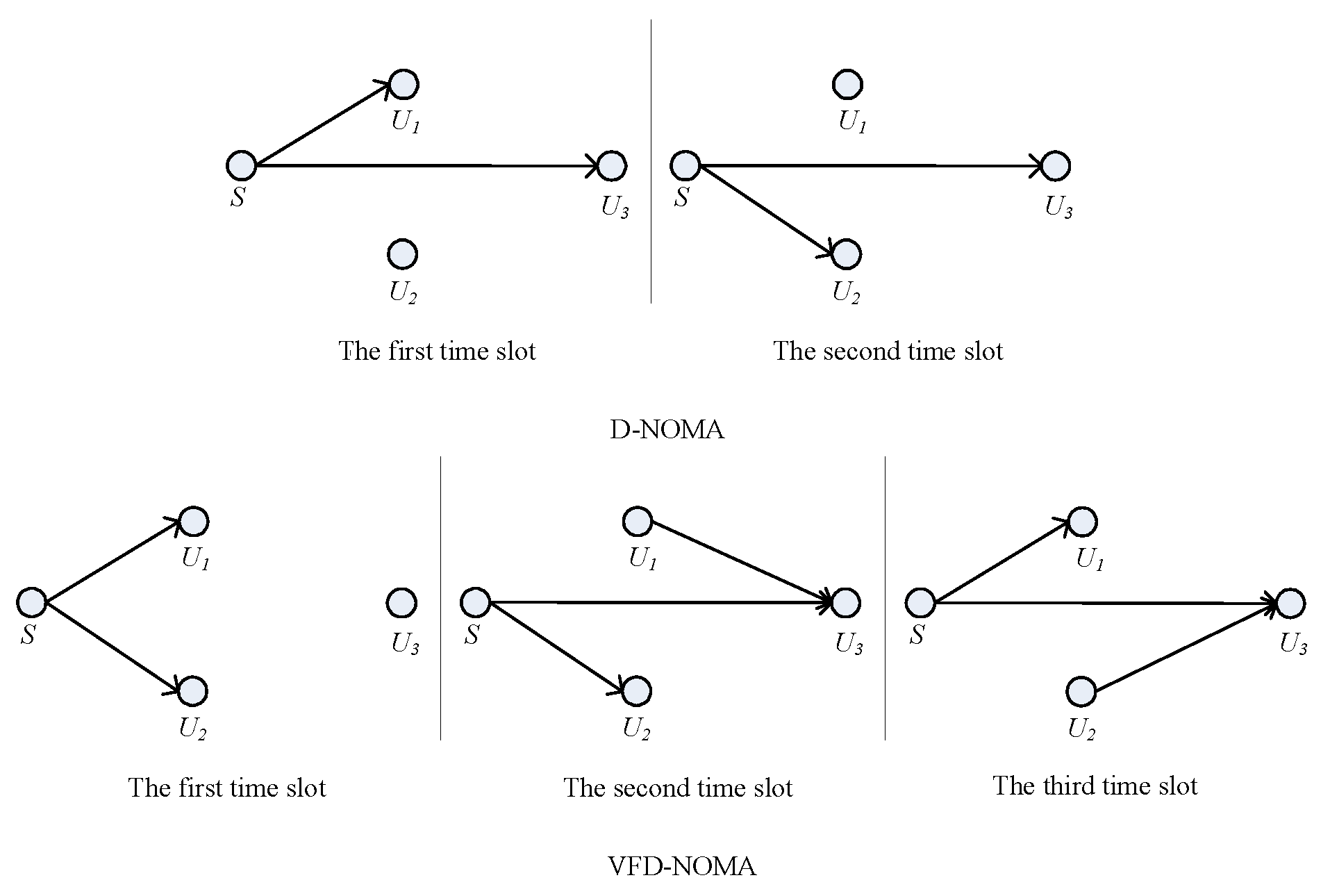
  • An incremental VFD-NOMA (I-VFD-NOMA) scheme is proposed in this study. When the SINR of direct link is greater than the given threshold, direct NOMA (D-NOMA) with two time slots is used. When the SINR of this link falls below the given threshold, VFD-NOMA with three time slots is adopted. In VFD-NOMA scheme, two energy harvesting (EH) enabled near users can be considered as relays for forwarding the information successively for the far user. The analytical expression of throughput for this I-VFD-NOMA system is derived with I-SIC.
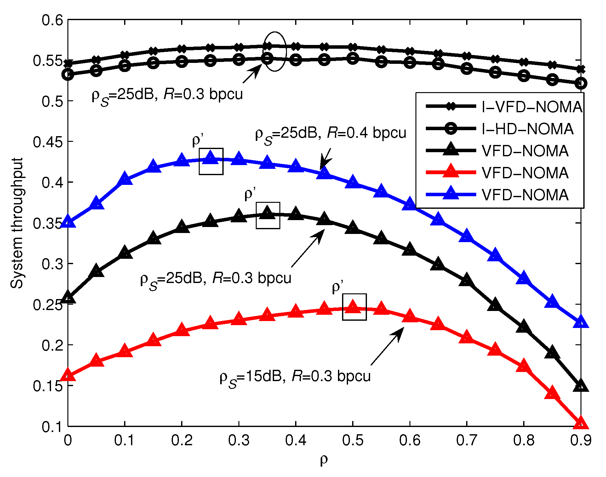
  • It is well known that power splitting factor affects the performance of the EH system greatly. So the optimal power splitting factor at relay that maximizes the throughput of VFD-NOMA system without direct link is derived in this study. Numerical and simulation results show that this optimal factor can improve system performance greatly.
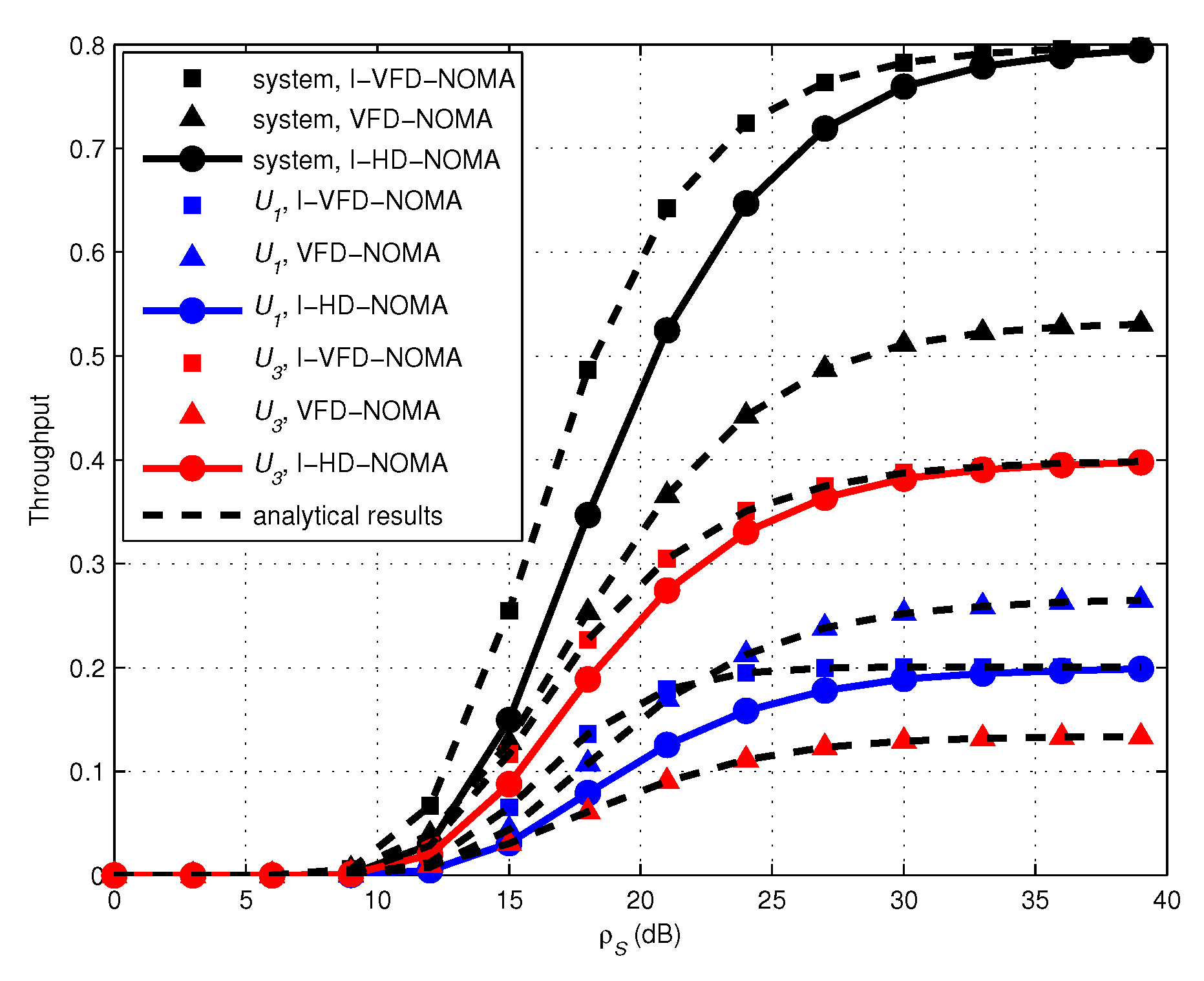
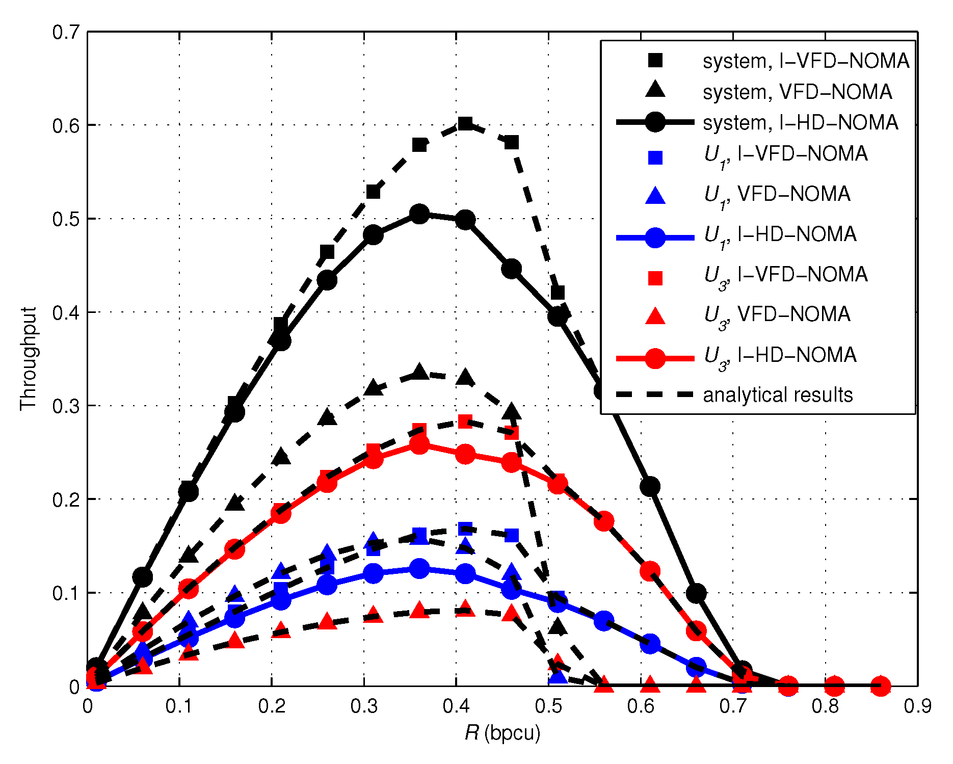
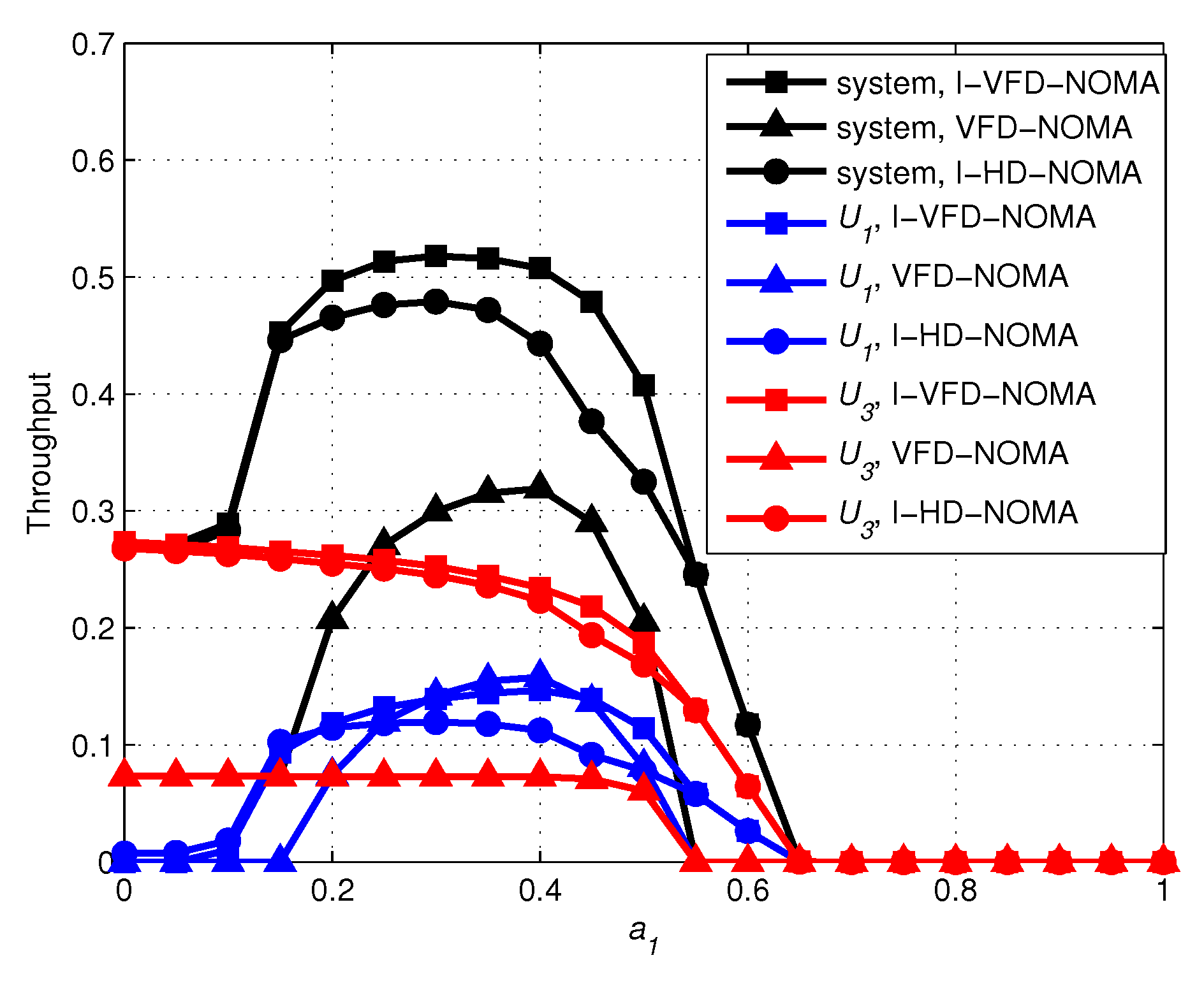
  • Finally, The throughput performance of incremental HD-NOMA (I-HD-NOMA) and VFD-NOMA schemes is compared with our scheme. Numerical and simulation results show that the proposed I-VFD-NOMA scheme has better performance than existing I-HD-NOMA and VFD-NOMA schemes.
  • The main novelty of this paper can be summarized as follows. (1) To the best of our knowledge, the proposed I-VFD-NOMA is the first time that the incremental relaying protocol is introduced into cooperative VFD-NOMA networks and the spectral efficiency can be further improved by this integration. (2) For the effective design of the proposed I-VFD-NOMA system, we provide an valuable insight into the I-SIC factor and optimal power splitting factor through detailed theoretical analysis and numerical results.
The rest of this paper is organized as follows. In Section 2, system model is introduced. The closed-form expressions of system throughput for the system with the direct link and without direct link are derived in Section 3. The optimal power splitting factor for the system without direct link is also derived in this part. Numerical and simulations results are presented in Section 4 and conclusions are drawn in Section 5.

2. System Model

In this part, we introduce models of I-VFD-NOMA system with direct link and VFD-NOMA system without direct link.

2.1. System Model for I-VFD-NOMA System

As shown in Figure 1, in our system, a source node S intends to communicate with three users ( U 1 , U 2 , U 3 ), U 1 and U 2 are close to S, but U 3 is far away from S. U 1 and U 2 can operate as EH relays with power splitting protocol. The channels between any transmitter and receiver are assumed to experience independent block Rayleigh fading and the additive white Gaussian noise of all links has a zero mean and equal variance N 0 . Let h S 1 , h S 2 , h S 3 , h 13 , h 23 and h 12 denote channel coefficients corresponding to the links, S- U 1 , S- U 2 , S- U 3 , U 1 - U 3 , U 2 - U 3 and U 1 - U 2 , respectively. The channel power gains of those hops G S 1 , G S 2 , G S 3 , G 13 , G 23 and G 12 are assumed to be exponentially distribution with parameters λ S 1 , λ S 2 , λ S 3 , λ 13 , λ 23 and λ 12 , respectively. All nodes are equipped with one antenna. The signal transmission schemes for the system with the direct link and without the direct link are presented in this and the following subsection, respectively.
When the direct link is available, I-VFD-NOMA protocol is adopted and S either uses D-NOMA mode or VFD-NOMA mode to send messages for three users. In the beginning of a transmission block, S transmits a pilot signal to U 3 . If U 3 finds that the SINR over the S- U 3 (i.e., direct) link is greater than a given threshold, it sends a 1-bit ACK to S. When S receives ACK, it adopts the D-NOMA mode which contains 2 time slots in one transmission block. In the first time slot of D-NOMA mode, S transmits a superimposed signal
x D N t 1 = a 1 P S x 1 + a 2 P S x 3 t 1 ,
where x 1 and x 3 t 1 are the signals for U 1 and U 3 respectively, P S is the transmission power of S, a 1 and a 2 are the power allocation coefficients for U 1 and U 3 . We assume that a 1 < a 2 and a 1 + a 2 = 1 . We also assume U 2 does not receive signal in this time slot. The received signals at U 1 and U 3 are given by
y 1 D N t 1 = h S 1 ( a 1 P S x 1 + a 2 P S x 3 t 1 ) + n 1 ,
y 3 D N t 1 = h S 3 ( a 1 P S x 1 + a 2 P S x 3 t 1 ) + n 3 ,
where n 1 and n 3 are the additive white Gaussian noise at U 1 and U 3 . All nodes are assumed to have the ability to apply SIC. When y 1 D N t 1 is received at U 1 , x 3 t 1 is demodulated first by treating x 1 as noise which is because x 3 t 1 is allocated more power. Conditioned on x 3 t 1 is demodulated successfully, U 1 can directly demodulated its own information x 1 after subtracting the interference of x 3 t 1 [17]. The received SINRs at U 1 for decoding x 3 t 1 and x 1 can be written as
γ 1 3 D N = G S 1 a 2 ρ S G S 1 a 1 ρ S + 1 ,
γ 1 1 D N = G S 1 a 1 ρ S β G S 1 a 2 ρ S + 1 ,
where ρ S = P S P S N 0 N 0 , β is the I-SIC factor ( 0 < β < 1 ) and β G S 1 a 2 ρ S is residual interference signal. U 3 decodes x 3 t 1 from y 3 D N t 1 and the corresponding SINR is given by
γ 3 3 , 1 D N = G S 3 a 2 ρ S G S 3 a 1 ρ S + 1 .
In the second time slot of D-NOMA mode, S transmits a superimposed signal
x D N t 2 = a 1 P S x 2 + a 2 P S x 3 t 2 ,
where x 2 and x 3 t 2 are the signals for U 2 and U 3 respectively. According to SIC, the received SINRs for decoding x 3 t 2 and x 2 at U 2 can be written as
γ 2 3 D N = G S 2 a 2 ρ S G S 2 a 1 ρ S + 1 ,
γ 2 2 D N = G S 2 a 1 ρ S β G S 2 a 2 ρ S + 1 .
The SINR for U 3 to decode its own message in this time slot can be written as
γ 3 3 , 2 D N = G S 3 a 2 ρ S G S 3 a 1 ρ S + 1 .
When receiving the pilot signal before transmission, if U 3 finds that the SINR over direct link falls below the given threshold, it sends a 1-bit NACK to S. Consequently S adopts VFD-NOMA mode which contains 3 time slots in one transmission block. In the first time slot, S sends a superimposed signal to U 1 which is given by
x V F D N t 1 = a 1 P S x 1 t 1 + a 2 P S x 3 ,
where x 1 t 1 and x 3 are the signals for U 1 and U 3 respectively. U 1 first harvests energy using power splitting protocol and then decodes the message of U 3 , if U 1 decodes x 3 successfully, it then subtracts x 3 from the received signal to detect its own information. Therefore, the received SINRs at U 1 for the decoding the information of U 3 and U 1 are given by
γ 1 3 V F D N = 1 ρ G S 1 a 2 ρ S 1 ρ G S 1 a 1 ρ S + 1 ,
γ 1 1 , 1 V F D N = 1 ρ G S 1 a 1 ρ S 1 ρ β G S 1 a 2 ρ S + 1 ,
where ρ is power splitting factor which means ρ percentage of received power is used for EH and ( 1 ρ ) percentage is used for message decoding at U 1 . In this time slot, U 2 also receives message from S, ρ percentage of received power is harvested and ( 1 ρ ) percentage is used for decoding the message of U 3 which is used for interference cancellation in the second time slot. U 3 does not receive signal in this time slot because selection combining (SC) is used in our system. SC is less complex than maximal ratio combining (MRC) and is a widely studied combining scheme in the literature.
As decode-and-forward (DF) scheme is used in our protocol, in the second time slot of VFD-NOMA mode, U 1 forwards the decoded signal x 3 to U 3 . Simultaneously, S transmits a new superimposed signal
x V F D N t 2 = a 1 P S x 2 + a 2 P S x 3
to U 2 in this time slot, where x 2 is the signal for U 2 . Accordingly, the received signals at U 2 is given by
y 2 V F D N t 2 = h S 2 a 1 P S x 2 + a 2 P S x 3 + h 12 P 1 x 3 + n 2 ,
where P 1 = η ρ P S G S 1 , η is the energy harvesting efficiency and n 2 is additive white Gaussian noise at U 2 . U 2 can remove interference signal, h 12 P 1 x 3 because it can estimate h 12 P 1 using side information of signal x 3 obtained during the first time slot. After removing the interference signal, the received signal at U 2 can be rewritten as
y 2 V F D N t 2 = h S 2 a 1 P S x 2 + a 2 P S x 3 + n 2 ,
With this observation, U 2 proceeds to use SIC to decode signal x 2 . x 3 is first detected with a SINR value of
γ 2 3 V F D N = G S 2 a 2 ρ S G S 2 a 1 ρ S + 1 .
After decoding x 3 successfully and then subtracting it from (16), x 2 is subsequently detected by U 2 with the SINR value of
γ 2 2 V F D N = G S 2 a 1 ρ S β G S 2 a 2 ρ S + 1 .
We have to notice that U 2 does not perform EH in this time slot because it has harvested energy in the first time slot. The SINR at U 3 to decode x 3 in this time slot is given by
γ 3 3 , 2 V F D N = η ρ ρ S G S 1 G 13 + G S 3 a 2 ρ S G S 3 a 1 ρ S + 1 .
From (19), we can see that the signal received at U 3 to detect its own message in the second time slot is a superimposed mixture which consists of signal sending from U 1 and signal sending from S.
During the third phase, U 2 relays the decoded signal x 3 to U 3 . Simultaneously, S transmits a new signal x 1 t 3 to U 1 with transmission power of a 1 P S . The observation at U 1 is given by
y 1 t 3 = a 1 P S h S 1 x 1 t 3 + P 2 h 12 x 3 + n 1 ,
where P 2 = η ρ P S G S 2 . Similar to U 2 ’s processing in the second time slot, U 1 can also remove interference signal P 2 h 12 x 3 in this time slot. The received SINR at U 1 to detect signal x 1 t 3 is given by
γ 1 1 , 3 V F D N = G S 1 a 1 ρ S .
The observation at U 3 in this time slot is given by
y 3 t 3 = a 1 P S h S 3 x 1 t 3 + P 2 h 23 x 3 + n 1
and the received SINR at U 3 to detect signal x 3 in this time slot is given by
γ 3 3 , 3 V F D N = η ρ ρ S G S 2 G 23 G S 3 a 1 ρ S + 1 .
Finally, SC is used at U 3 and the final SINR to detect x 3 is given by
γ 3 V F D N = max γ 3 3 , 2 V F D N , γ 3 3 , 3 V F D N .
Remark 1.(1) From (24), we can see that the final SINR to decode x 3 in VFD-NOMA mode is obtained by adopting SC. MRC can also be used to get the better performance, but MRC requires the individual signals from each path to be time-aligned, cophased and optimally weighted by their own fading amplitude, and then summed [2]. It is a complex optimal combining scheme as it requires the information of all channel fading parameters. SC is simply the process of selecting the signal of the branch with the highest SINR and no information of other branches is required. So we use SC in our scheme to improve the performance and ensure the complexity is not so high.
(2) If the transmission is in VFD-NOMA mode, S transmits one signal for U 3 and two signals for U 1 in one transmission block. This is because in this mode, the SINR over the direct link is very low, if S transmits two signal for U 3 , the throughput of U 3 will be decreased compared with one signal which will be demonstrated by the simulation in Section 5. But in D-NOMA mode, the SINR over the direct link is good enough, so U 3 receive two signals in one transmission block.

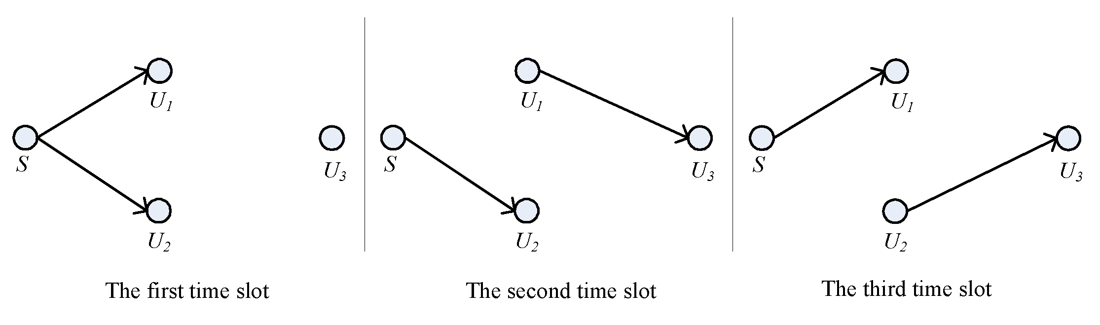
2.2. System Model for the VFD-NOMA System without Direct Link

When the direct link is not available because of long distance or obstructions, only VFD-NOMA can be used for transmission. In this case, VFD-NOMA with no direct link is adopted. The detail of this scheme is demonstrated as follows.
As shown in Figure 2, the first time slot is the same as VFD-NOMA with direct link which is stated in (11)–(13). In the second time slot of this mode, U 1 relays the decoded symbol to U 3 and concurrently, S transmits a new superimposed mixture signal to U 2 . (14)–(18) are also applicable for this mode. As there is no direct link between S and U 3 , (19) can be modified as
γ 3 3 , 2 V F D N = η ρ ρ S G S 1 G 13 .
Similarly, (20)–(21) can also be used in the third time slot of this mode and (23) can be modified as
γ 3 3 , 3 V F D N = η ρ ρ S G S 2 G 23 .
The reason for the discrepancy between (23) and (26) is also that there is no direct link. The final SINR to detect x 3 using SC at U 3 in this mode is given by
γ 3 V F D N = max γ 3 3 , 2 V F D N , γ 3 3 , 3 V F D N .

3. Throughput Analysis

Here we analyze the throughput performance of I-VFD-NOMA system and VFD-NOMA system (When direct link is not available).

3.1. Throughput of I-VFD-NOMA System

When the direct link is available, the system adopts I-VFD-NOMA scheme. Let the target rates for the successful decoding of x 1 , x 2 and x 3 be R 1 , R 2 and R 3 (bits per channel use(bpcu)), respectively. When D-NOMA mode is adoptable, 2 time slots are needed and the corresponding threshold SINR values are γ t h 1 D N = 2 2 R 1 1 , γ t h 2 D N = 2 2 R 2 1 and γ t h 3 D N = 2 2 R 3 1 , respectively. Since the VFD-NOMA mode requires 3 time slots, the threshold SINR can be expressed as γ t h 1 V F D N = 2 3 R 1 1 , γ t h 2 V F D N = 2 3 R 1 1 and γ t h 3 V F D N = 2 3 R 1 1 , respectively. In the D-NOMA mode, if x 1 and x 2 are successfully delivered to U 1 and U 2 , the achieved rates equal R 1 R 1 2 2 and R 2 R 2 2 2 , respectively, while if x 3 t 1 and x 3 t 2 are successfully delivered to U 3 , the rate equals R 3 . In the VFD-NOMA mode, the corresponding rates are 2 R 1 R 1 3 3 , R 2 R 2 3 3 and R 3 R 3 3 3 , respectively. Under the delay-limited transmission mode, where the users are served with constant rates, the system throughput depends on the outage probability experienced by the users and is determined as
τ I V F D N = P 1 D N R 1 2 + P 2 D N R 2 2 + P 3 D N R 3 + P 1 V F D N 2 R 1 3 + P 2 V F D N R 2 3 + P 3 V F D N R 3 3 .
In (28), P 1 D N , P 2 D N and P 3 D N are the probabilities with which signals are successfully decoded at U 1 , U 2 and U 3 in the D-NOMA mode, respectively. P 1 V F D N , P 2 V F D N and P 3 V F D N are the probabilities with which signals are successfully decoded at respective users in the VFD-NOMA mode. Now, according to the above analysis, P 1 D N can be expressed as
P 1 D N = Pr γ 3 3 , 1 D N > γ t h 3 D N , γ 1 3 D N > γ t h 3 D N , γ 1 1 D N > γ t h 1 D N = Pr G S 3 a 2 ρ S G S 3 a 1 ρ S + 1 > γ t h 3 D N Pr G S 1 a 2 ρ S G S 1 a 1 ρ S + 1 > γ t h 3 D N , G S 1 a 1 ρ S β G S 1 a 2 ρ S + 1 > γ t h 1 D N = exp γ t h 3 D N a 2 ρ S a 1 ρ S γ t h 3 D N λ S 3 exp θ 1 λ S 1 ,
where θ 1 = max γ t h 3 D N a 2 ρ S a 1 ρ S γ t h 3 D N , γ t h 1 D N a 1 ρ S a 2 ρ S γ t h 1 D N β and γ 3 3 , 1 D N > γ t h 3 D N is application condition of D-NOMA mode. Notice that (29) is derived under the independent fading assumption. We also have to notice that a 2 a 1 γ t h 1 D N > 0 and a 1 a 2 γ t h 1 D N β > 0 must be satisfied, if not, P 1 D N will be zero. Similarly, P 2 D N can be written as
P 2 D N = Pr γ 3 3 , 1 D N > γ t h 3 D N , γ 2 3 D N > γ t h 3 D N , γ 2 2 D N > γ t h 2 D N = exp γ t h 2 D N a 2 ρ S a 1 ρ S γ t h 2 D N λ S 3 exp θ 2 λ S 1 ,
where θ 2 = max γ t h 3 D N a 2 ρ S a 1 ρ S γ t h 3 D N , γ t h 2 D N a 1 ρ S a 2 ρ S γ t h 2 D N β . P 3 D N can be written as
P 3 D N = Pr γ 3 3 , 1 D N > γ t h 3 D N = exp γ t h 3 D N a 2 ρ S a 1 ρ S γ t h 3 D N λ S 3 .
When VFD-NOMA mode is adopted, according to (12), (13) and (21), P 1 V F D N can be written as
P 1 V F D N = Pr γ 3 3 , 1 D N < γ t h 3 D N , γ 1 3 V F D N > γ t h 3 V F D N , γ 1 1 , 1 V F D N > γ t h 1 V F D N , γ 1 1 , 3 V F D N > γ t h 1 V F D N = Pr G S 3 a 2 ρ S G S 3 a 1 ρ S + 1 < γ t h 3 D N , 1 ρ G S 1 a 2 ρ S 1 ρ G S 1 a 1 ρ S + 1 > γ t h 3 V F D N , 1 ρ G S 1 a 1 ρ S 1 ρ β G S 1 a 2 ρ S + 1 > γ t h 1 V F D N , G S 1 a 1 ρ S > γ t h 1 V F D N = 1 exp γ t h 3 D N a 2 ρ S a 1 ρ S γ t h 3 D N λ S 3 exp θ 3 λ S 1 .
where θ 3 = max γ t h 3 V F D N 1 ρ a 2 ρ S a 1 ρ S γ t h 3 V F D N , γ t h 1 V F D N 1 ρ a 1 ρ S a 2 ρ S γ t h 1 V F D N β and γ 3 3 , 1 D N < γ t h 3 D N is application condition of VFD-NOMA mode. According to (17) and (18), P 2 V F D N can be written as
P 2 V F D N = Pr γ 3 3 , 1 D N < γ t h 3 D N , γ 2 3 V F D N > γ t h 3 V F D N , γ 2 2 V F D N > γ t h 2 V F D N = Pr G S 3 a 2 ρ S G S 3 a 1 ρ S + 1 < γ t h 3 D N , G S 2 a 2 ρ S G S 2 a 1 ρ S + 1 > γ t h 3 V F D N , G S 2 a 1 ρ S β G S 2 a 2 ρ S + 1 > γ t h 2 V F D N = 1 exp γ t h 3 D N a 2 ρ S a 1 ρ S γ t h 3 D N λ S 3 exp θ 4 λ S 2 ,
where θ 4 = max γ t h 3 V F D N a 2 ρ S a 1 ρ S γ t h 3 V F D N , γ t h 2 V F D N a 1 ρ S a 2 ρ S γ t h 2 V F D N β . According to (19), (23) and (24), P 3 V F D N can be written as
P 3 V F D N = Pr γ 3 3 , 1 D N < γ t h 3 D N , γ 1 3 V F D N > γ t h 3 V F D N , γ 2 3 V F D N > γ t h 3 V F D N , γ 3 V F D N > γ t h 3 V F D N J 1 + Pr γ 3 3 , 1 D N < γ t h 3 D N , γ 1 3 V F D N > γ t h 3 V F D N , γ 2 3 V F D N < γ t h 3 V F D N , γ 3 3 , 2 V F D N > γ t h 3 V F D N + Pr γ 3 3 , 1 D N < γ t h 3 D N , γ 1 3 V F D N < γ t h 3 V F D N , γ 2 3 V F D N > γ t h 3 V F D N , γ 3 3 , 3 V F D N > γ t h 3 V F D N ,
in which J 1 can be expressed as
J 1 = Pr G S 3 a 2 ρ S G S 3 a 1 ρ S + 1 < γ t h 3 D N , 1 ρ G S 1 a 2 ρ S 1 ρ G S 1 a 1 ρ S + 1 > γ t h 3 V F D N , G S 2 a 2 ρ S G S 2 a 1 ρ S + 1 > γ t h 3 V F D N , max η ρ ρ S G S 1 G 13 + G S 3 a 2 ρ S G S 3 a 1 ρ S + 1 , η ρ ρ S G S 2 G 23 G S 3 a 1 ρ S + 1 > γ t h 3 V F D N = Pr G S 3 a 2 ρ S G S 3 a 1 ρ S + 1 < γ t h 3 D N , 1 ρ G S 1 a 2 ρ S 1 ρ G S 1 a 1 ρ S + 1 > γ t h 3 V F D N , G S 2 a 2 ρ S G S 2 a 1 ρ S + 1 > γ t h 3 V F D N Pr G S 3 a 2 ρ S G S 3 a 1 ρ S + 1 < γ t h 3 D N , 1 ρ G S 1 a 2 ρ S 1 ρ G S 1 a 1 ρ S + 1 > γ t h 3 V F D N , G S 2 a 2 ρ S G S 2 a 1 ρ S + 1 > γ t h 3 V F D N , η ρ ρ S G S 1 G 13 + G S 3 a 2 ρ S G S 3 a 1 ρ S + 1 < γ t h 3 V F D N , η ρ ρ S G S 2 G 23 G S 3 a 1 ρ S + 1 < γ t h 3 V F D N = Pr G S 3 a 2 ρ S G S 3 a 1 ρ S + 1 < γ t h 3 D N , 1 ρ G S 1 a 2 ρ S 1 ρ G S 1 a 1 ρ S + 1 > γ t h 3 V F D N , G S 2 a 2 ρ S G S 2 a 1 ρ S + 1 > γ t h 3 V F D N J 2 Pr G S 3 a 2 ρ S G S 3 a 1 ρ S + 1 < γ t h 3 D N , 1 ρ G S 1 a 2 ρ S 1 ρ G S 1 a 1 ρ S + 1 > γ t h 3 V F D N , η ρ ρ S G S 1 G 13 + G S 3 a 2 ρ S G S 3 a 1 ρ S + 1 < γ t h 3 V F D N J 3 × Pr G S 3 a 2 ρ S G S 3 a 1 ρ S + 1 < γ t h 3 D N , G S 2 a 2 ρ S G S 2 a 1 ρ S + 1 > γ t h 3 V F D N , η ρ ρ S G S 2 G 23 G S 3 a 1 ρ S + 1 < γ t h 3 V F D N J 4 .
Note that J 2 can be easily obtained according to the channel assumption above and the derivation is omitted here. Let G S 1 = X , G S 3 = Y and G 13 = Z , J 3 becomes
J 3 = 1 Pr X < θ 5 , Y > θ 6 ,   Z < γ t h 3 V F D N + X ρ S a 1 γ t h 3 V F D N a 2 η ρ ρ S Y ,
where θ 5 = γ t h 3 D N a 2 a 1 γ t h , 3 ρ S and θ 6 = γ t h 3 V F D N 1 ρ a 2 a 1 γ t h 3 V F D N ρ S . Since X, Y and Z are exponentially distribution, J 3 can be written as
J 3 = 0 θ 5 1 λ S 3 exp x λ S 3 d x θ 6 1 λ S 1 exp y λ S 1 d y × 0 γ t h 3 V F D N + x ρ S a 1 γ t h 3 V F D N a 2 η ρ ρ S y 1 λ 13 exp z λ 13 d z = 1 exp θ 5 λ S 3 exp θ 6 λ S 2 0 θ 5 1 λ S 3 exp x λ S 3 d x θ 6 1 λ S 1 exp y λ S 1 d y exp Δ y J 5 ,
where Δ = γ t h 3 V F D N + x ρ S a 1 a 1 γ t h 3 V F D N a 2 η ρ ρ S λ 13 . By expanding exp Δ y using Maclaurin series and using (3.352.2)and (3.353.1) in [18], J 5 can be determined as
J 5 = 1 exp θ 5 λ S 3 exp θ 6 λ S 1 + θ 7 λ S 3 θ 7 λ S 3 exp θ 5 λ S 3 1 + θ 5 λ S 3 + θ 8 1 exp θ 5 λ S 3 + n = 2 1 n n ! r = 0 n C n r θ 7 n θ 8 n r r ! λ S 3 r + 2 exp θ 5 λ S 3 k = 0 r r ! k ! θ 5 k λ S 3 r k + 2 × exp θ 6 λ S 1 q = 1 n 1 q 1 ! 1 n q 1 n 1 ! θ 6 k λ S 1 n q 1 n 1 n 1 ! λ S 1 n E i θ 6 λ S 1 ,
where θ 7 = max γ t h 3 V F D N a 2 ρ S a 1 ρ S γ t h 3 V F D N , γ t h 1 V F D N a 1 ρ S a 2 ρ S γ t h 1 V F D N β , θ 8 = γ t h 3 V F D N η ρ ρ S and E i · is exponential integral function [18]. Submitting (38) into (37), we can get the closed-form of J 3 . The derivation of J 4 is similar to J 3 , so we omit it here. With the closed-form of J 2 , J 3 and J 4 , J 1 can be obtained. The derivation of other parts in (34) is similar to the derivation of J 1 and we omit them too. Now submitting (29)–(34) into (28), we can get the closed-form expression of τ I V F D N .

3.2. Through of VFD-NOMA System without Direct Link

When the direct link is not available, only VFD-NOMA scheme can be used. Similar to the analysis in Section 3.1, the system throughput can be expressed as
τ V F D N = P 1 V F D N 2 R 1 3 + P 2 V F D N R 2 3 + P 3 V F D N R 3 3 .
Similar to (32), P 1 V F D N can be obtained as
P 1 V F D N = Pr γ 1 3 V F D N > γ t h 3 V F D N , γ 1 1 , 1 V F D N > γ t h 1 V F D N , γ 1 1 , 3 C N > γ t h 1 V F D N = exp θ 7 1 ρ λ S 1 .
The difference between (32) and (40) is that incremental mode cannot be used when direct link is not available. Similarly, P 2 V F D N can be derived as
P 2 V F D N = Pr γ 2 3 V F D N > γ t h 3 V F D N , γ 2 2 V F D N > γ t h 2 V F D N = exp θ 4 λ S 2 .
According to the VFD-NOMA scheme, P 3 V F D N can be written as
P 3 V F D N = Pr γ 1 3 V F D N > γ t h 3 V F D N , γ 2 3 V F D N > γ t h 3 V F D N , γ 3 V F D N > γ t h 3 V F D N J 6 + Pr γ 1 3 V F D N > γ t h 3 V F D N , γ 2 3 V F D N < γ t h 3 V F D N , γ 3 3 , 2 V F D N > γ t h 3 V F D N + Pr γ 1 3 V F D N < γ t h 3 V F D N , γ 2 3 V F D N > γ t h 3 V F D N , γ 3 3 , 3 V F D N > γ t h 3 V F D N .
where J 6 can be expressed as
J 6 = Pr γ 1 3 V F D N > γ t h 3 V F D N , γ 2 3 V F D N > γ t h 3 V F D N , max γ 3 3 , 2 V F D N , γ 3 3 , 3 V F D N > γ t h 3 V F D N = Pr 1 ρ G S 1 a 2 ρ S 1 ρ G S 1 a 1 ρ S + 1 > γ t h 3 V F D N , G S 2 a 2 ρ S G S 2 a 1 ρ S + 1 > γ t h 3 V F D N J 7 Pr 1 ρ G S 1 a 2 ρ S 1 ρ G S 1 a 1 ρ S + 1 > γ t h 3 V F D N , η ρ ρ S G S 1 G 13 < γ t h 3 V F D N J 8 × Pr G S 2 a 2 ρ S G S 2 a 1 ρ S + 1 > γ t h 3 V F D N , η ρ ρ S G S 2 G 23 < γ t h 3 V F D N J 9 .
In (43), J 7 can be easily get with the channel assumption above and we omit the derivation here. With the help of Maclaurin series and (3.353.1) in [18], J 8 can be written as
J 8 = exp θ 6 λ S 1 + θ 8 λ S 1 λ S 3 Ei θ 6 λ S 1 + n = 2 θ 8 n λ S 3 n n ! λ S 1 exp θ 6 λ S 1 × k = 1 n 1 k 1 ! n 1 ! λ S 1 n k 1 θ 6 k 1 n 1 ! λ S 1 n 1 Ei θ 6 λ S 1 .
The derivation of J 9 is the same as J 8 , so we omit it here. Invoking J 7 , J 8 and J 9 into (43), we can get the closed-form expression of J 6 . The derivation of other parts in (42) is similar to J 6 and we give no more details. Invoking (40), (41) and (42) into (39), we can get the closed-form expression of τ V F D N .

3.3. Optimal Power Splitting Factor of VFD-NOMA Mode without Direct Link

When the direct link is not available, if ρ is very small, τ V F D N will decrease since the forwarding power of U 1 and U 2 will be very small. Similarly, τ V F D N will also reduce if ρ tends to unity because increasing of ρ may lead to information decoding failure at U 1 and U 2 . So there exists the optimal ρ that maximizes the throughput of VFD-NOMA system without direct link and we will derive the expression of this value in this part. First, when ρ S , we rewrite J 8 as
J 8 = γ t h 3 V F D N 1 ρ ρ S a 2 a 1 γ t h 3 V F D N 1 λ S 1 exp x λ S 1 d x 0 γ t h 3 V F D N η ρ ρ S x 1 λ 13 exp y λ 13 d y = γ t h 3 V F D N 1 ρ ρ S a 2 a 1 γ t h 3 V F D N 1 λ S 1 exp x λ S 1 1 exp γ t h 3 V F D N η ρ ρ S x λ 13 d x a γ t h 3 V F D N 1 ρ ρ S a 2 a 1 γ t h 3 V F D N 1 λ S 1 exp x λ S 1 γ t h 3 V F D N η ρ ρ S x λ 13 d x = γ t h 3 V F D N η ρ ρ S λ S 1 λ 13 E i γ t h 3 V F D N 1 ρ ρ S a 2 a 1 γ t h 3 V F D N λ S 1 b γ t h 3 V F D N η ρ ρ S λ S 1 λ 13 exp γ t h 3 V F D N 1 ρ ρ S a 2 a 1 γ t h 3 V F D N λ S 1 ÷ 1 + γ t h 3 V F D N 1 ρ ρ S a 2 a 1 γ t h 3 V F D N λ S 1 c γ t h 3 V F D N η ρ ρ S λ S 1 λ 13 1 γ t h 3 V F D N 1 ρ ρ S a 2 a 1 γ t h 3 V F D N λ S 1 ÷ 1 + γ t h 3 V F D N 1 ρ ρ S a 2 a 1 γ t h 3 V F D N λ S 1 d γ t h 3 V F D N η ρ ρ S λ S 1 λ 13 .
In (45), steps (a) and (c) are obtained by using the approximation exp x 1 x ( 0 < x < < 1 ) when ρ S . Step (b) is obtained by using a tight lower bound E i x exp x exp x 1 + x 1 + x . Step (d) is obtained by using ρ S . The derivation of approximate expressions of J 7 and J 9 is similar as (45), so we omit it here. With approximate expressions of J 7 , J 8 and J 9 , we can get the approximation of J 6 . The approximations of other two parts of P 3 V F D N can also be derived as J 6 . From (41), we can see that P 2 V F D N is not relating to ρ , so we do not need to take this part into consideration when optimizing ρ . When ρ S , the approximation of P 1 V F D N can also be written as
P 1 V F D N 1 θ 7 1 ρ λ S 1 .
(46) is obtained as step (a) in (45). To maximize the throughput of VFD-NOMA system without direct link, we have to substitute the probabilities in (39) with approximations above and solve the equation 2 R 1 3 P 1 V F D N ρ + R 3 3 P 3 V F D N ρ = 0 . The optimal ρ can be obtained by solving the resulting equation. When all the system parameters are substituted into the equation, it is easy to solve the equation using Shengjin formula and there is no need to list the detailed solution process here. We will give the detailed results in the simulation part.
Remark 2.
There is no need to derive the optimal ρ to maximize the throughput of I-VFD-NOMA mode. This is because the effect of ρ in I-VFD-NOMA mode is not so obvious as in the VFD-NOMA mode without direct link which will be verified in the simulation part.

4. Numerical Results and Discussions

In this section, computer simulations are performed to validate the above theoretical analysis. We introduce the channel model E h i j 2 = d i j d i j d 0 d 0 α , where d i j is the distance between node i and j and α = 3 is the path loss exponent. In our simulation, the S- U 3 line is perpendicular to U 1 - U 3 line and the intersection point of two lines is the midpoint of U 1 - U 3 line as shown in Figure 3. The horizontal distance between S and U 1 is set as d. The other parameters are set as follows: d S U 3 = 30 m, d U 1 U 2 = 5 m, R 1 = R 2 = R 3 = R , β = 0.2, η = 0.5, a 1 = 1/3 and a 2 = 2/3.
Figure 4 illustrates the performance of the proposed schemes and incremental HD-NOMA (I-HD-NOMA) scheme versus ρ S with R = 0.3 bpcu , d = 15m and ρ = 0.5 . The difference between I-VFD-NOMA and I-HD-NOMA is that when the direct link is not good enough, I-HD-NOMA requires a total of 4 equal orthogonal time slots which is similar to [19]. From the figure, we can see that simulation and theoretical results match very well with each other for all users in I-VFD-NOMA and VFD-NOMA systems. As for system throughput and throughput of U 3 , it can be observed that I-VFD-NOMA achieves the best performance compared with other two schemes. This is because the proposed I-VFD-NOMA save one time slot compared with I-HD-NOMA and VFD-NOMA can not utilize the direct link. We can also see that I-HD-NOMA has the better performance compared with VFD-NOMA which is because the direct link of I-HD-NOMA system is available and I-HD-NOMA does not need to use energy to estimate h 12 P 1 and h 12 P 2 , so it saves energy to forward the signal. As for U 1 , I-VFD-NOMA has the best performance compared with other two schemes when the ρ S is below 22 dB. But when ρ S is high, VFD-NOMA scheme has the best performance. The reason is that when ρ S is high, the D-NOMA mode is adopted for I-VFD-NOMA and I-HD-NOMA schemes and U 1 only receive information once in this mode, but U 1 can receive information twice in VFD-NOMA mode. It is also worth noting that when ρ > 30 dB , I-VFD-NOMA and I-HD-NOMA have the same performance for system throughput and throughput of all users. This behavior is caused by that when ρ increases, the SINR of direct link is enough for successful decoding, both I-VFD-NOMA and I-HD-NOMA adopt D-NOMA mode, so they have the same performance.
Figure 5 plots throughput of three schemes versus R with ρ = 0.5 , d = 15 m and ρ S = 25 dB . It is shown that the analytical curves perfectly match the Monte Carlo simulation results for I-VFD-NOMA and VFD-NOMA. The throughput of system and all users first increases and then decreases with the increase of R. This is because when R is greater than a certain value, increasing of R increases the outage probabilities. The optimal value of R to maximize the system throughput or throughput of any users can easily be obtained by a one-dimension exhaustive search. Further, the proposed I-VFD-NOMA scheme outperforms other two schemes for the system throughput and the throughput of U 3 which demonstrates the superiority of our scheme. Although VFD-NOMA outperforms I-VFD-NOMA for U 1 in some cases, the performance degrades badly for U 1 in VFD-NOMA scheme as R increases. Since the theoretical analyses agree well with the simulations, we will only plot the analytical results in the remaining figures.
Figure 6 plots the performance of three schemes versus d with ρ = 0.5 , ρ S = 25 dB and R = 0.3 bpcu . We can observe that the performance degrades for U 1 , U 3 and the whole system as d increases. This is because high values of d leads to information decoding failure and decreasing of forwarding power at U 1 and U 2 . Although increasing d leads to improvement of channel power gain of second hop, forwarding power decreases more at U 1 and U 2 as d increases. We can also observe that the performance of VFD-NOMA falls fastest in three schemes as d 1 increases. This behavior is caused by the fact that there is no direct link for VFD-NOMA scheme. The direct link remains constant as d changes, so the performance of I-VFD-NOMA and I-HD-NOMA tend to be constant as d 1 increases.
Figure 7 shows the system throughput versus ρ with d = 15 m for three systems. We can see that ρ has a great influence on performance of VFD-NOMA scheme and the system throughput reduces for both lower and higher values of ρ . Further, an optimal ρ exists that maximizes the throughput of VFD-NOMA system. But ρ has little influence on the other two systems. This is because when the direct link is available, energy harvesting is not necessary in D-NOMA mode, so the ρ does not affect the performance so dramatically. Figure 7 also shows the impact of target rate R and ρ S on the optimal ρ for VFD-NOMA system. When R is increased, the threshold SINR increases, which implies that optimal ρ must decrease since more power is required for successful decoding. likewise, when ρ S is increased, the proportion of energy harvesting can be reduced, so the optimal ρ will be reduced. From Figure 7, we can find a ρ which is marked as ρ in each curve of VFD-NOMA system corresponding to the maximum value of system throughput. Both ρ and the optimal results of ρ derived from Section 3.3 under various cases are depicted in Table 1, the close agreement of them confirms the correctness of our analysis.
Figure 8 plots the the performance of I-VFD-NOMA scheme versus a 1 with ρ = 0.5 , ρ S = 25 dB , d = 15 m and R = 0.3 bpcu . It can be observed that a 1 has a significant impact on the system performance and the throughput of systems first goes up and then goes down with the increase of a 1 . The performances of U 1 have the same trend, but does not change much for U 3 . This is because when SIC is used at U 1 and U 2 , increasing a 1 can increase the probability of correct decoding the information of themselves, but can also decreasing the probability of correct decoding the information of U 3 . So there exists an optimal a 1 to maximize throughput of U 1 and U 2 . From (19), (23) and (24), it can be easily seen that increasing a 1 can decrease the performance of U 3 , but G S 3 is small (If G S 3 is greater than the threshold, D-NOMA mode will be selected), so a 1 has little impact on the performance of U 3 . The system throughput is the sum of throughput of U 1 , U 2 and U 3 , so the system throughput has the same trend as U 1 .

5. Conclusions

In this paper, an I-VFD-NOMA scheme integrated with EH was proposed and the closed-form expression of system throughput was derived considering I-SIC. The analytical expression of system throughput for VFD-NOMA system was also derived when the direct link is not available. Moreover, the optimal power splitting factor for this VFD-NOMA system was obtained. Numerical and simulation results show that the proposed I-VFD-NOMA scheme is more practical than existing I-HD-NOMA and VFD-NOMA schemes and the optimal power splitting factor can improve the performance of VFD-NOMA system greatly.

Funding

This research received no external funding.

Institutional Review Board Statement

Not applicable.

Informed Consent Statement

Not applicable.

Data Availability Statement

Not available online. Please contact corresponding author for data requests.

Conflicts of Interest

The authors declare no conflict of interest.

Abbreviations

The following abbreviations are used in this manuscript:
I-VFD-NOMAIncremental virtual full-duplex non-orthogonal multiple access
EHEnergy harvesting
DFDecode-and-forward
I-SICImperfect successive interference cancellation
SCSelection combining
OMAOrthogonal multiple access
5GFifth generation
HDHalf-duplex
SISelf-interference
SINRSignal-to-interference plus noise ratio
D-NOMADirect NOMA
I-HD-NOMAIncremental HD-NOMA
MRCMaximal ratio combining
bpcubits per channel use

References

  1. Ding, Z.; Yang, Z.; Fan, P.; Poor, H.V. On the performance of non-orthogonal multiple access in 5G systems with randomly deployed users. IIEEE Signal Process. Lett. 2014, 21, 1501–1505. [Google Scholar] [CrossRef] [Green Version]
  2. Kara, F.; Kaya, H. On the error performance of cooperative-NOMA with statistical CSIT. IEEE Commun. Lett. 2015, 23, 128–131. [Google Scholar] [CrossRef]
  3. Liu, G.; Wang, Z.; Hu, J.; Ding, Z.; Fan, P. Cooperative NOMA broadcasting/multicasting for low-latency and high-reliability 5G cellular V2X communications. IEEE Internet Things J. 2019, 6, 7828–7838. [Google Scholar] [CrossRef]
  4. Kader, M.F.; Shin, S.Y.; Leung, V.C.M. Full-duplex non-orthogonal multiple access in cooperative relay sharing for 5G systems. IEEE Trans. Veh. Technol. 2018, 67, 5831–5840. [Google Scholar] [CrossRef]
  5. Wang, X.; Jia, M.; Ho, I.W.; Guo, Q.; Lau, F.C.M. Exploiting full-duplex two-way relay cooperative non-orthogonal multiple access. IEEE Trans. Commun. 2019, 67, 2716–2729. [Google Scholar] [CrossRef]
  6. Ren, C.; Zhang, H.; Wen, J.; Chen, J.; Tellambura, C. Successive two-way relaying for full-duplex users with generalized self-interference mitigation. IEEE Trans. Wireless Commun. 2019, 18, 63–76. [Google Scholar] [CrossRef]
  7. Zhang, Z.; Ma, Z.; Xiao, M.; Karagiannidis, G.K.; Ding, Z.; Fan, P. Two-timeslot two-way full-duplex relaying for 5G wireless communication networks. IEEE Trans. Commun. 2016, 64, 2873–2887. [Google Scholar] [CrossRef] [Green Version]
  8. Jose, J.; Shaik, P.; Bhatia, V. VFD-NOMA under imperfect SIC and residual inter-relay interference over generalized nakagami-m fading channels. IEEE Commun. Lett. 2021, 25, 646–650. [Google Scholar] [CrossRef]
  9. Liau, Q.Y.; Leow, C.Y.; Ding, Z. Amplify-and-forward virtual full-duplex relaying-based cooperative NOMA. IEEE Wireless Commun. Lett. 2018, 7, 464–467. [Google Scholar] [CrossRef]
  10. Laneman, J.N.; Tse, D.N.C.; Wornell, G.W. Cooperative diversity in wireless networks: Efficient protocols and outage behavior. IEEE Trans. Inf. Theory 2004, 50, 3062–3080. [Google Scholar] [CrossRef]
  11. Reshma, K.; Babu, A.V. Throughput analysis of energy harvesting enabled incremental relaying NOMA system. IEEE Commun. Lett. 2020, 24, 1419–1423. [Google Scholar] [CrossRef]
  12. Shukla, A.K.; Singh, V.; Upadhyay, P.K.; Kumar, A.; Moualeu, J.M. Performance analysis of energy harvesting-assisted overlay cognitive NOMA systems with incremental relaying. IEEE Open J. Commun. Soc. 2021, 2, 1558–1576. [Google Scholar] [CrossRef]
  13. Guo, C.; Guo, C.; Zhang, S.; Ding, Z. UAV-Enabled NOMA networks analysis with selective incremental relaying and imperfect CSI. IEEE Trans. Veh. Technol. 2020, 69, 16276–16281. [Google Scholar] [CrossRef]
  14. Yue, X.; Liu, Y.; Yao, Y.; Li, X.; Liu, R.; Nallanathan, A. Secure communications in a unified non-orthogonal multiple access framework. IEEE Trans. Wireless Commun. 2020, 19, 2163–2178. [Google Scholar] [CrossRef] [Green Version]
  15. Im, G.; Lee, J.H. Outage probability for cooperative NOMA systems with imperfect SIC in cognitive radio networks. IEEE Trans. Commun. Lett. 2019, 23, 692–695. [Google Scholar] [CrossRef]
  16. Bisen, S.; Shaik, P.; Bhatia, V. On performance of energy harvested cooperative NOMA under imperfect CSI and imperfect SIC. IEEE Trans. Veh. Technol. 2021, 70, 8993–9005. [Google Scholar] [CrossRef]
  17. Liu, Y.; Qin, Z.; Elkashlan, M.; Gao, Y.; Hanzo, L. Enhancing the physical layer security of non-orthogonal multiple access in large-scale networks. IEEE Trans. Wireless Commun. 2017, 16, 1656–1672. [Google Scholar] [CrossRef]
  18. Gradshteyn, I.; Ryzhik, I. Table of Integrals, Series and Products, 1st ed.; Academic Press: San Diego, CA, USA, 1994. [Google Scholar]
  19. Kim, J.B.; Lee, I.H. Non-orthogonal multiple access in coordinated direct and relay transmission. IEEE Commun. Lett. 2015, 19, 2037–2040. [Google Scholar] [CrossRef]
Figure 1. Illustration of I-VFD-NOMA system.
Information 13 00216 g001
Figure 2. Illustration of VFD-NOMA system without direct link.
Information 13 00216 g002
Figure 3. Illustration of system setting.
Information 13 00216 g003
Figure 4. Throughput of system, U 1 and U 3 versus ρ S .
Information 13 00216 g004
Figure 5. Throughput of system, U 1 and U 3 versus R.
Information 13 00216 g005
Figure 6. Throughput of system, U 1 and U 3 versus d.
Information 13 00216 g006
Figure 7. System throughput versus ρ .
Information 13 00216 g007
Figure 8. Throughput of system, U 1 and U 3 versus a 1 .
Information 13 00216 g008
Table 1. Optimal ρ obtained by two methods.
Parameters ρ Optimal ρ Derived from 3.3
ρ S  = 15 dB, R = 0.3 bpcu0.24480.2358
ρ S  = 25 dB, R = 0.3 bpcu0.36060.3722
ρ S  = 25 dB, R =  0.4 bpcu0.42840.4335
Publisher’s Note: MDPI stays neutral with regard to jurisdictional claims in published maps and institutional affiliations.

