Article

Double-Layer Mobile Edge Computing-Enabled Power Line Inspection in Smart Grid Networks

1
Information & Telecommunication Branch Company, East Inner Mongolia Electric Power Co., Ltd., Hohhot 010010, China
2
School of Information and Communication Engineering, Beijing University of Posts and Telecommunications, Beijing 100876, China
*
Author to whom correspondence should be addressed.
Information 2022, 13(4), 167; https://doi.org/10.3390/info13040167
Submission received: 7 December 2021 / Revised: 14 March 2022 / Accepted: 22 March 2022 / Published: 25 March 2022
(This article belongs to the Special Issue Wireless Communications, Networking and Applications)

Abstract

:
Unmanned aerial vehicles (UAVs) have the advantages of flexibility, low cost, and good communication channel gain. In recent years, the inspection of power grid systems supported by UAVs has been widely used. However, due to the constraint of wireless channels and UAVs, it is impossible to transmit video content to the surveillance center. To solve this problem, in this study, a new mobile edge computing (MEC) technology-enabled power line inspection scheme for smart grid networks was designed. Within this scheme, a double-layer MEC architecture is proposed. In the upper-level layer, several UAVs installed with MEC equipment can locally process inspection videos with higher propriety. At the same time, the remaining tasks with lower priority are performed by the terrestrial base stations. In addition, a cost minimization problem is proposed and solved by the alternating optimization algorithm. The simulation results show that the proposed algorithm can significantly reduce the energy consumption of the system.

1. Introduction

Mobile edge computing (MEC) is a scheme that places computing and storage resources on the edge of the mobile network to alleviate the network delay problem [1,2]. In a smart grid scenario, high inspection accuracy cannot be guaranteed via human patrols due to large-scale distribution and a complex geographical environment. Simultaneously, the labor, transportation, and equipment costs can be enormously high. Using MEC-enabled unmanned aerial vehicles (UAVs) to inspect remote units (RUs, such as power towers and energy generators) in transformer substations is a promising technical scheme to solve the above problems [3]. UAVs fly periodically over RUs in the network supporting UAVs, and RUs can report working status or alarm information to UAVs. This method offloads the task of RU inspection to the MEC server of UAVs and makes full use of the flexibility and good channel gain of UAVs.
In smart grid scenarios, RUs usually have different priorities. The RU inspection tasks with high priority should be completed first, whereas the tasks with low priority can be completed within the maximum tolerance delay. However, the existing studies only consider optimizing energy consumption within the maximum tolerant delay, while ignoring the task priority in actual scenarios. In addition, previous works only consider a single UAV that serves users. However, it is impossible for a single UAV to complete a large number of computing tasks since the ground base station is far away and the resources of a UAV are limited. To this end, in this study, a new MEC architecture of double-layer UAVs and multiple ground base stations was designed to complete the computing tasks of RU inspection. Under the constraint of computing resources, the upper-level UAV optimizes the allocation of resources. The UAV completes some RU inspection tasks to maximize the priority of RUs and minimize their transmission energy consumption. The remaining RUs relay their status to the lower UAV. Under the constraint of time delay, the UAV trajectory and bit allocation are optimized to achieve the goal of minimizing transmission energy consumption between RUs and UAVs.
The main contributions of this paper are summarized as follows:
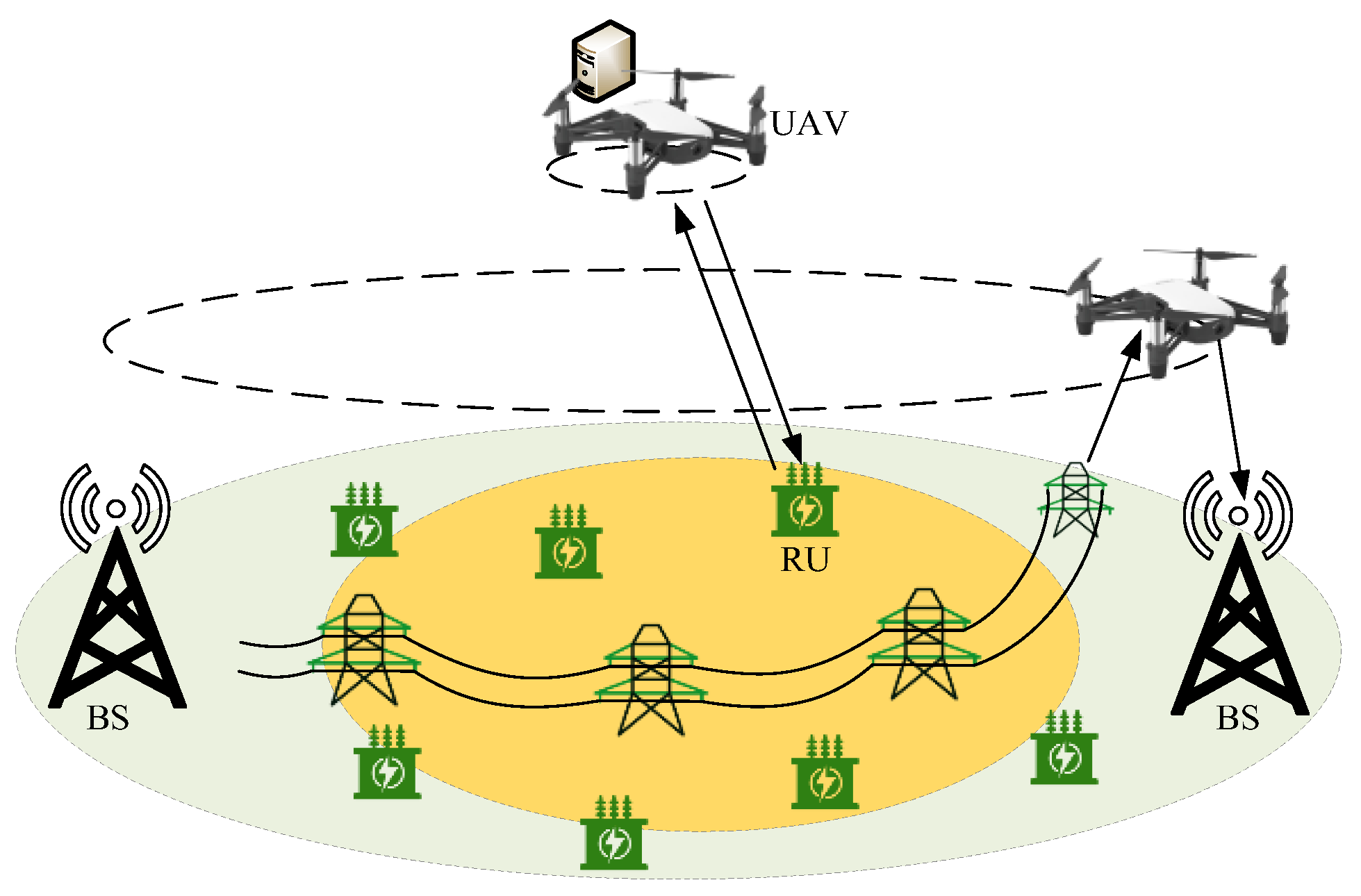
  • A double-layer MEC-enabled power line inspection scheme is proposed in this paper. In the upper-level layer, several UAVs equipped with MEC servers can locally process inspection videos with higher propriety, while the remaining tasks with lower priority can be processed by the terrestrial base stations.
  • An integer linear programming problem is formulated to jointly optimize the accessed RUs’ priority and the transmission energy consumption. The problem is solved by the proposed alternating optimization algorithm.
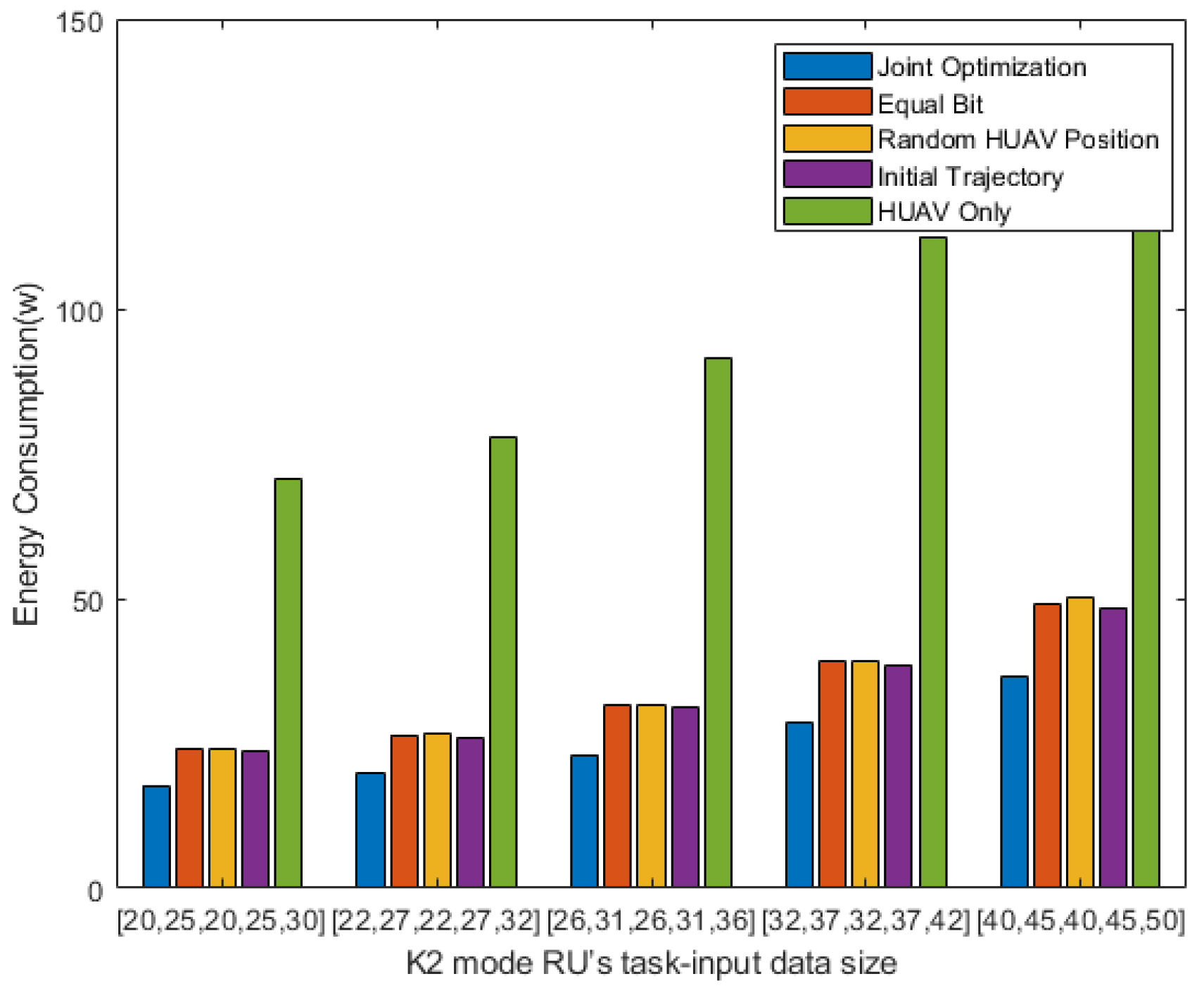
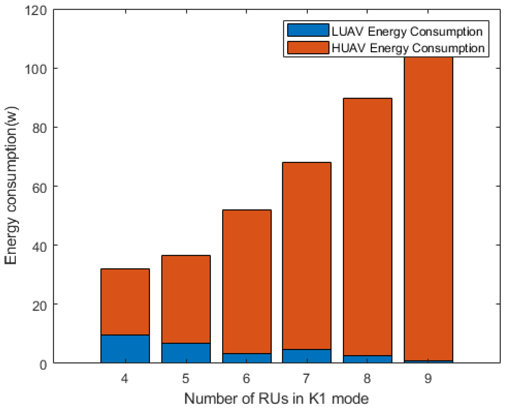
  • The results of the simulation show that the proposed scheme can significantly reduce the energy consumption of the considered system.
The rest of this paper is organized as follows. Section 2 gives a brief overview of related studies. The model of the considered system is introduced in Section 3. Section 4 presents the formulation of the problem, to which the solution is demonstrated in Section 5. Next, the simulation results and discussions are shown in Section 6. Finally, Section 7 concludes this paper.

2. Related Works

In recent years, UAV-assisted mobile edge computing has become a popular research topic. Due to the limited size of the UAV itself and the limited battery capacity it carries, energy consumption is significant for UAV-assisted mobile edge computing. In [4], a joint rate decomposition problem is proposed to optimize the allocation of transmission link rates between two antenna arrays on unmanned aerial vehicles, and finally minimize energy consumption in centralized and distributed MEC modes. Study [5] considers the cooperative offloading of joint base stations and unmanned aerial vehicles. By jointly optimizing the location, communication, and computing resource allocation and task segmentation decisions of unmanned aerial vehicles, the weighted sum of the service delay of all Internet of Things devices and the energy consumption of unmanned aerial vehicles is minimized. The work of [6] considers a deployment mechanism of multiple UAVs to realize load balancing and improve UAV mission execution efficiency. Study [7] is different from others because it considers merging tasks at several hot spots based on the geography. Its goal is to improve server utilization and UAV scheduling. In [8], new optimization parameters are considered, and parameters such as CPU frequency and transmission power are considered to minimize unmanned aerial vehicles’ total energy consumption. The two algorithms are compared, and the conclusion is drawn that trajectory optimization plays a leading role in reducing system energy consumption. In contrast, acceleration optimization has a significant influence on the total energy demand for unmanned aerial vehicles. Some studies consider using wireless power transfer (WPT) technology to equip base stations with the ability to provide energy. Study [9] considers establishing a resource allocation framework in partial and binary offload modes to maximize weighted sum computation bits. In their work, the UAV not only calculates the user’s tasks but also supplies energy to the user through WPT. Considering the limited power consumption of unmanned aerial vehicles, work [10] considers an energy-saving resource allocation scheme that uses SWIPT technology to supply power to unmanned aerial vehicles, and optimizes the power allocation ratio of base stations to unmanned aerial vehicles and the time slot allocation ratio of unmanned aerial vehicles to minimize energy consumption.
Based on the overview of the related research, it can be seen that none of the previous works related to UAV-assisted MEC has considered the task priority in actual smart grid scenarios. In addition, dealing with the limited resources of a single UAV by fully utilizing the architecture of double-layer UAVs remains an unsolved problem.

3. System Model

We consider a two-layer UAV architecture to complete RU inspection tasks, as is shown in Figure 1. The upper unmanned aerial vehicle carries an MEC server, which is located at a fixed position to serve ground RUs. The lower unmanned aerial vehicle makes periodic flights to relay the RUs’ status to the ground base station.
In this scenario, BS is a terrestrial base station with a built-in high computing performance server. Table 1 provides the description of frequently used symbols. We use K to represent the number of RUs, 1 k K . The status of RU k can be described as I k = { L k , C k , T k , A k } , where L k represents the size of input status data, C k represents the number of cycles required to compute 1 bit, and T k represents the maximum tolerated delay of the RU. A k represents the priority of the RU’s status. We use M to represent the number of BS, 1 m M . Since a two-layer UAV architecture is used in this paper, we consider using a variable a k { 0 , 1 } , k K to represent the RU’s access mode. When the variable is 1, it means the RU selects the upper layer UAV. When the variable is 0, it means that the lower UAV is selected to relay the RU’s status to the ground base station.

3.1. Communication Model

Without losing generality, we construct a three-dimensional Cartesian coordinate system model. The horizontal coordinates of the RU and the ground base station are z k = ( x k , y k ) and z B S [   m   ] = ( x B S [ m ] , y B S [ m ] ) , respectively. The upper UAV hovers at z U A V H = ( x U A V H , y U A V H , h U A V H ) to serve RUs. The initial horizontal position of the lower UAV is z U A V L = ( x U A V L , y U A V L ) . It flies at a fixed altitude value H . We assume that the flight period of UAV is T . T is divided into N time slots, and Δ describes each time slot. Since Δ is small, we assume that the position of the UAV will not change in each time slot. Therefore, the horizontal trajectory K of the UAV in the i -th time slot can be represented by discrete-time positions. The trajectory constraints of UAV are as follows:
q [ 1 ] = q [ N ] q [ i + 1 ] q [ i ] 2 ( v max Δ ) 2 , i τ
where · represents the Euclidean distance and v max represents the maximum flight speed (meters/second).
In this paper, we consider using the FDMA protocol to access the upper UAV for RUs that choose to offload the status to the upper UAV. For RUs that choose to relay their status to the lower-level UAV, we consider using the TDMA protocol to access the lower-level UAV.
In the UAV auxiliary network, the UAV’s flying height is generally much higher than that of ground RUs. The line-of-sight (Los) channel of the UAV communication link is less damaged than other channels, so the Los channel is selected for the UAV wireless channel. The gain between the lower UAV and BS, and the gain between the upper-layer UAV and RU k in the i -th slot, can be written as:
h B S L ( i , m ) = ρ 0 H 2 + q [ i ] z B S [ m ] 2 , i N , m M h k L [ i ] = ρ 0 H 2 + q [ i ] z k 2 , k K , i N h k H = ρ 0 ( h U A V H ) 2 + z U A V H z k 2 , k K
where ρ 0 represents the unit channel gain (the channel gain when the distance from the UAV is 1 m and the transmission power is 1 W).

3.2. Computing Model

RUs have two ways to report their status, which can be offloaded to the upper UAV for calculation or offloaded to the lower UAV and relayed to the base station for calculation.
(1)
Offloading to Upper UAV
The upper UAV hovers at a fixed height to serve the RU. The RU and the UAV use the Los channel to transmit through the FDMA protocol. To ensure fairness, we allocate the same bandwidth to each RU to transmit data. The transmission speed between UAV and the RU can be written as:
R k U 2 H = B 1 K 1 log 2 ( 1 + P k h k H σ 2 ) , k K 1
where B 1 is the total communication bandwidth between the upper UAV and RU, and K 1 is the RU set that chooses to offload to the upper UAV. P k is the maximum transmission power of RU k and σ 2 is the power of noise. To improve the signal-to-noise ratio (SNR), we let RUs use the maximum power to transmit. h k H is the channel gain between RU k and UAV.
When the RU offloads its status to the upper UAV, the RU’s total transmission energy consumption can be written as:
t k = L k R k U 2 H , k K 1 E k H = P k t k , k K 1 E H = k K 1 E k H
(2)
Offloading to Lower UAV
The lower unmanned aerial vehicle makes frequent flights over the RUs and relays the RU’s status to the ground base station for execution. We consider dividing the RU’s time slot into two parts: one part transmits the status to the lower UAV, and the other part relays the status to the ground base station by the UAV.
The transmission rate between the RU and the lower UAV in the i -th time slot can be written as:
R k U 2 L [ i ] = B 2 log 2 ( 1 + p k h k [ i ] σ 2 ) , k K 2
where B 2 is the total communication bandwidth between the lower UAV and RU, and K 2 is the RU set that chooses to offload to the lower UAV. h k [ i ] is the channel gain between RU and the lower UAV in the i -th slot.
Let us set the bit offloaded by RU in the i -th slot as L k [ i ] . Then, there are the following constraints. This constraint means that RU must offload all bits in N time slots:
i = 1 N L k [ i ] = L k , k K 2
The following formula can express the transmission energy consumption between the RU and the lower UAV:
E k U 2 L = i N p k L k [ i ] R k U 2 L [ i ]
The lower UAV will select the nearest base station for the relay according to the channel gain, and the transmission rate between the UAV and the base station in the i -th time slot can be written as:
h B S [ i ] = max { h B S L ( i , m ) } , m M R k L 2 E [ i ] = B 3 log 2 ( 1 + p U A V h B S [ i ] σ 2 ) , k K 2
where B 3 is the communication bandwidth between the UAV and AP, and p U A V is the transmission power between the UAV and the ground base station. h B S [ i ] is the channel gain between the i -th UAV and AP communication.
The transmission energy consumption between UAV and ground base station in the i -th time slot can be written as:
E k L 2 E = i N p U A V L k [ i ] R k L 2 E [ i ]
The total energy consumption in the lower mode can be written as:
E L = k K 2 E k L E k L = E k U 2 L + E k L 2 E , k K 2

4. Problem Formulation

This problem has two objectives. Our first goal is to optimize the allocation of computing resources under the constraint of upper-level UAV computing resources to maximize the accessed RUs’ priority:
P 1 : max a k k K a k A k C 1 : a k { 0 , 1 } , k K C 2 : k K 1 C k L k f U A V H
where C 1 means that each RU can only choose one offloading method, and C 2 means that the sum of computing resources that choose to offload to the upper UAV cannot exceed the UAV’s computing capability.
The goal is to minimize the transmission energy consumption between RUs and UAVs. The transmission energy consumption can be composed of two parts: the transmission energy consumption offloaded by the RU to the double-layer UAV and the transmission energy consumption offloaded by the UAV to the base station.
P 2 : E = k K ( a k E H + ( 1 a k ) E L ) C 1 : a k { 0 , 1 } , k K C 2 : i = 1 n L k [ i ] = L k , k K 2 C 3 : q [ 1 ] = q [ N ] C 4 : q [ i + 1 ] q [ i ] 2 ( v max Δ ) 2 , i τ C 5 : k = 1 K 2 L k [ i ] C k , i N , k K 2 C 6 : 0 < x U A V H < x max C 7 : 0 < y U A V H < y max C 8 : T < t M A X
where C 1 means that RU can only choose one offload method. C 2 indicates that the RU that chooses to offload to the lower UAV mode needs to offload the status of N time slots. C 3 represents the periodic flight of the lower UAV. C 4 indicates that the UAV’s maximum horizontal distance in a one-time slot cannot exceed the threshold. C 5 means that the bits offloaded by all RUs to the UAV in a one-time slot cannot exceed the UAV calculation threshold. C 6 and C 7 represents the range of coordinates of the upper UAV. C 8 indicates that the lower UAV’s flight period is less than the maximum tolerated delay of the RU.

5. Proposed Algorithm

5.1. Resource Allocation of Upper UAV

This problem optimizes the allocation of computing resources of unmanned aerial vehicles to achieve the highest total priority of accessed RUs. The knapsack problem is an NP-complete problem of combinatorial optimization. We can transform this problem into a 0–1 knapsack problem to solve it. The upper UAV allocates resources to RUs under resource capacity limitation, thus maximizing the priority of completed RU tasks:
P 1.1 : max a k k K a k A k C 1 : a k { 0 , 1 } , k K C 2 : k K 1 C k L k f U A V H

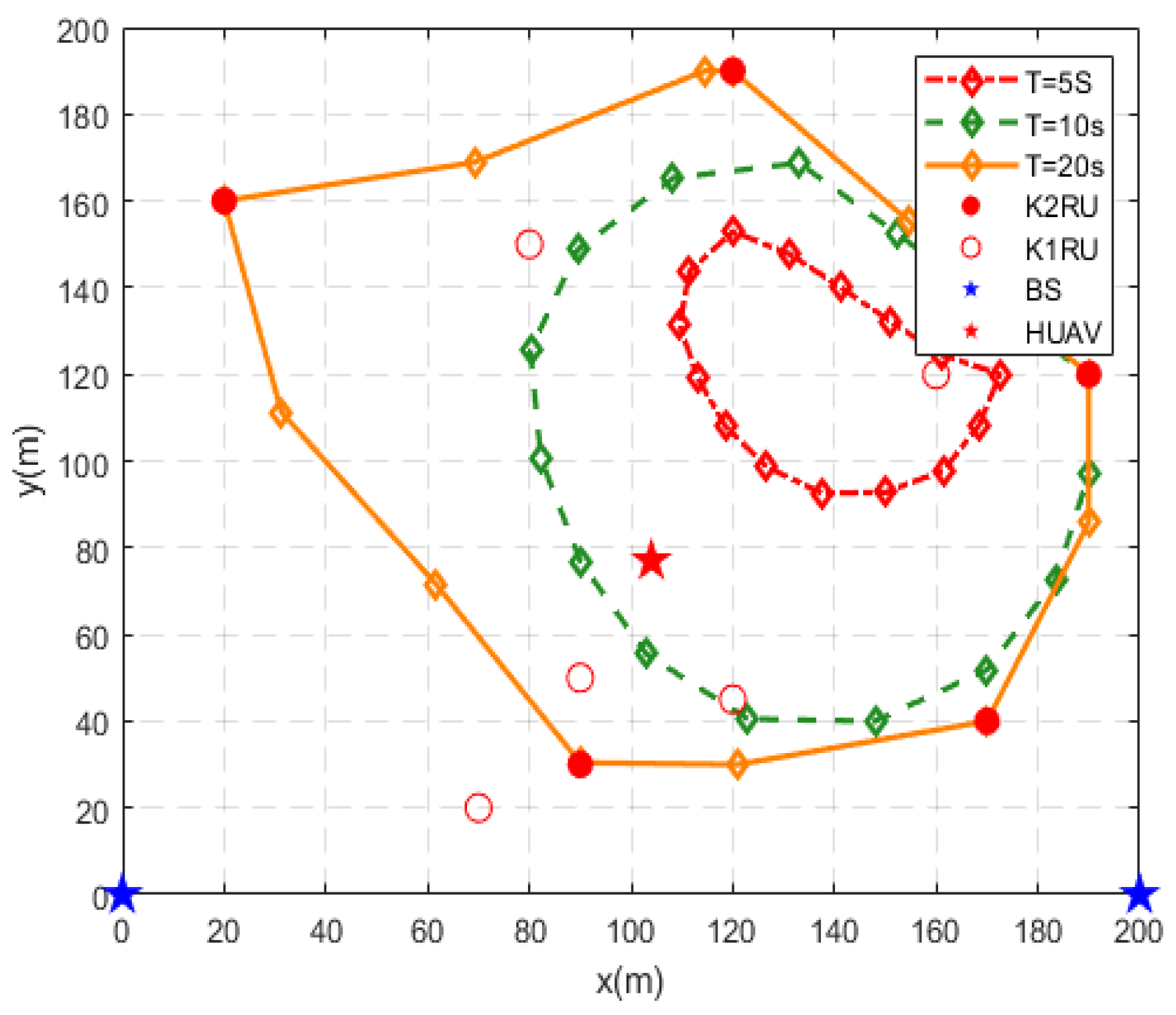
5.2. Location Optimization of Upper UAV

We need to optimize the position of the UAV to minimize the energy consumption of the upper mode. Because the scene is small, the traversal algorithm is used to obtain the optimal solution:
P 2.1 : min l o c k K 1 E k H C 6 : 0 < x U A V H < x max C 7 : 0 < y U A V H < y max

5.3. Joint Optimization of Lower UAVs

We optimize the lower UAV trajectory and the bit allocation of RUs to minimize the total energy consumption. We designed an improved alternating optimization algorithm to decouple the optimization variables, as shown in Algorithm 1. The algorithm jointly optimizes the UAV flight trajectory sub-problem and bit allocation sub-problem through the iterative method. The algorithm can achieve better results.
P 2.2 : min { L k [ i ] , q [ i ] } k K 2 E L C 2 : i = 1 n L k [ i ] = L k , k K 2 C 3 : q [ 1 ] = q [ N ] C 4 : q [ i + 1 ] q [ i ] 2 ( v max Δ ) 2 , i τ C 5 : k = 1 K 2 L k [ i ] C k , i N , k K 2
(1)
Bit optimization sub-problem
Given the lower UAV trajectory, we can derive the number of bits that the RU optimally allocates in each time slot:
P 2.2.1 : min { L k [ i ] } k K 2 E L C 2 : i = 1 n L k [ i ] = L k , k K 2 C 5 : k = 1 K 2 L k [ i ] C k , i N , k K 2
When we expand P 2.2.1, we can see that the problem solved is a mixed-integer linear programming problem only related to L k [ i ] . We used the intlinprog function of MATLAB to solve the integer linear programming problem.
Algorithm 1. Time Resource Allocation Optimization.
1: Initialize Q ( i ) , the error tolerance threshold ε , and index of iteration i = 0 ;
2: The energy distribution of the upper UAV is obtained by (13);
3: The position of the upper UAV is obtained by (14), and then the minimum energy consumption of the upper UAV is obtained;
4: repeat
5: Obtain L ( i ) with Q ( i ) thorough (16);
  Obtain Q ( i + 1 ) with L ( i ) thorough (18)
   i = i + 1 ;
until  E sum ( i + 1 ) E sum ( i ) < ε .
P 2.2.2 : min { L k [ i ] } k K 2 i N ( p U A V R k L 2 E [ i ] + p k R k U 2 L [ i ] ) L k [ i ] C 2 : i = 1 n L k [ i ] = L k , k K 2 C 5 : k = 1 K 2 L k [ i ] C k , i N , k K 2
(2)
Trajectory optimization sub-problem
After we find L k [ i ] , we can determine the trajectory of the lower UAV.
P 2.2.3 : min { L k [ i ] } k K 2 i N ( a 1 log 2 ( 1 + b 1 ( c 1 ) ) + a 2 log 2 ( 1 + b 2 c 2 ) ) a 1 = p U A V L k [ i ] B 3 , a 2 = p k L k [ i ] B 2 b 1 = p U A V ρ 0 σ 2 , b 2 = p k ρ 0 σ 2 c 1 = H 2 + q [ i ] z B S [ m ] 2 , c 2 = ( H 2 + q [ i ] z k 2 )
For simple calculation, we substitute the trajectory of UAV in the i -th slot as x into P 2.2.3 and extract some constants at the same time. By solving the second derivative of x , we can find that the above problem is nonconvex. We can solve the nonconvex problem using the Taylor expansion. We use the P4 Taylor expansion to replace the objective function with the first-order Taylor expansion. Where f ( x 0 ) and f ( x 0 ) are Taylor coefficients expanded at q x 0 , respectively, the converted P 2.2.4 problem is convex and can be solved using the CVX toolbox in MATLAB.
P 2.2.4 : min { x = q [ i ] } k = 1 K 2 i = 1 N ( f ( x 0 ) + f ( x 0 ) ( x x 0 ) )
We iterated many times and repeated the above two steps. Under the condition of keeping other variables unchanged, the UAV trajectory and bit allocation are alternately optimized. When the reduction in energy consumption is less than the threshold, the iteration is stopped, and the current calculation result is the optimal value.
E sum ( i + 1 ) E sum ( i ) < ε
Next, we provide a computational complexity analysis of the proposed algorithm. In Algorithm 1, each step has its own calculation method. In step 2, the 0–1 knapsack problem can be solved by a greedy algorithm, in which the time complexity is O ( K log K ) , where K is the number of RUs. In step 3, the time complexity of the traversal algorithm can be represented as O ( c ) , where c is the covered area of the considered scenario. In step 5, the calculation of the first sub-step has exponential time complexity, of which the minimum value is O ( 2 N K 2 ) , where N is the number of time slots and K 2 is the number of RUs in K2 mode. Since the second sub-step is an unconstrained optimization problem with many possible solutions, its time complexity depends on the specific method.

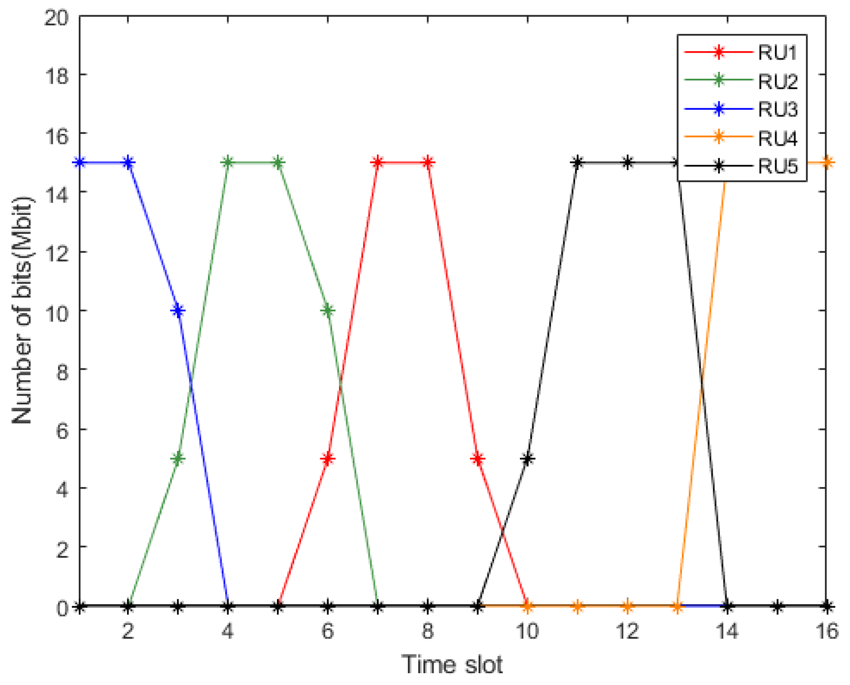
6. Simulation Results and Discussions

In this section, we present the simulation results to evaluate the proposed algorithm’s performance and efficiency. We assume ten ( K = 10) RUs are randomly distributed in the 200 m × 200 m two-dimensional area. Two BSs are located in the lower-left corner and the lower-right corner of the two-dimensional area. Each RU has a different status. The communication bandwidth between the upper UAV and the RU is 10 MHz. The communication bandwidth between the lower UAV and the RU is 5 MHz, and the communication bandwidth between the lower UAV and the ground base station is 5 MHz. The upper UAV provides services to RUs at a fixed position at 100 m. In comparison, the lower UAV flies periodically at a fixed height of 50 m, with a computing capacity of 1200 MHz and a maximum flight speed of 40 m/s. Other parameters and their references are shown in Table 2.
According to other articles, we chose the following strategies to compare the performance with the algorithm proposed in this paper: the Local Computing policy, where RUs only compute locally; the HUAV Only strategy, which only considers all RUs served by upper-level unmanned aerial vehicles; the Equal Bit strategy, in which RUs divide the statuses equally into time slots and offload them to lower-level unmanned aerial vehicles; the Initial Trajectory strategy, in which the lower UAV flies at a constant speed during flight; the Random HUAV Position strategy, in which the upper UAV serves some RUs at a random location; and the Joint Optimization strategy, which is an improved alternating optimization algorithm proposed in this paper.
As shown in Figure 2, as the flight period T of the lower unmanned aerial vehicle increases, the unmanned aerial vehicle’s trajectory is closer to K2 RUs. When T = 10   s , the trajectory is biased towards the two ground base stations below. The reason for this is that in order to ensure good communication with ground base stations, unmanned aerial vehicles can only be far away from RUs. We find that if unmanned aerial vehicles have an extended flight time, they can provide better services for RUs. Simultaneously, due to the need to relay the status to the ground base station, the ground base station’s position is also an essential factor affecting the trajectory of the UAV.
Figure 3 shows the relationship between the RU’s status size and each scheme’s energy consumption in K2 mode when the UAV’s flight time is 20 s. The performance of the “HUAV Only” scheme is much worse than that of other schemes, which can explain the necessity of deploying dynamic services of double-layer unmanned aerial vehicles and lower-layer unmanned aerial vehicles. The results of the other three schemes are not much different. Thus, it can be seen that bit allocation, upper UAV position deployment, and trajectory optimization have similar effects on the algorithm. As the K2 mode RUs’ status size increases, the gap between the above three energy consumption results and the proposed algorithm gradually increases. These results verify that the algorithm proposed in this paper not only improves the computing power of the MEC system, but also significantly reduces the energy consumption of the RUs’ computing status.
Figure 4 shows the offloading of five RUs which choose K2 mode in N time slots. From the figure and transmission rate, it can be seen that RUs will offload their status as much as possible when the UAV approaches them, to obtain better communication quality and further reduce transmission time. In one time slot, we allow multiple RUs to offload their status. However, we must meet the restriction that the number of offloading statuses in a one-time slot is less than the computational capacity of the UAV.
Figure 5 shows the relationship between the number of RUs that choose K1 mode and the proportion of upper and lower UAV energy consumption. It can be seen that the upper UAV consumes more energy than the lower UAV because the upper UAV has a limited bandwidth allocation and needs to be equally distributed to K1 mode RUs, resulting in higher energy consumption. Due to the limitation of UAV flight time and maximum computation bits in the time slot, the number of RUs that the lower UAV can serve is limited, so the number of RUs that choose K1 mode is at least 4. As shown from the figure, the lower the number of RUs that choose K1 mode, the higher the proportion of lower-level unmanned aerial vehicles. This is because, as the number of RUs that choose K2 decreases, the fewer benefits will be achieved by planning the allocation of unmanned aerial vehicle trajectory bits. To summarize, the allocation of upper-level unmanned aerial vehicles and lower-level unmanned aerial vehicles is significant. Only a reasonable allocation can minimize the total energy consumption.

7. Conclusions

In this study, a new MEC architecture of a double-layer UAV and multiple ground base stations was designed to help RUs report their status. First, the upper UAV collects some RUs’ status to maximize the priority and minimize the energy consumption of the RUs. We transform the problem into a 0–1 knapsack problem to solve it. The remaining RUs relay their status to the lower UAV. Under the constraint of time delay, the UAV trajectory and bit allocation are optimized to achieve the goal of minimizing transmission energy consumption between RUs and UAV. In order to solve this non-convex problem, we designed an improved alternating optimization algorithm to decouple variables. According to the simulation results, the algorithm has better energy consumption performance than other algorithms, reflecting the necessity of double-layer UAVs serving RUs. In future works, we will further consider the mobility of RUs and investigate its impact on the optimal resource allocation and the trajectory of UAVs. In addition, comprehensive performance comparisons of different optimization strategies proposed in related studies will be provided in our future works.

Author Contributions

Investigation, S.L., X.Z. and H.X.; supervision, H.Z.; writing—original draft, X.Z.; writing—review & editing, Z.L. All authors have read and agreed to the published version of the manuscript.

Funding

This research received no external funding.

Informed Consent Statement

Not applicable.

Conflicts of Interest

The authors declare no conflict of interest.

References

  1. Li, H.; Shou, G.; Hu, Y.; Guo, Z. Mobile Edge Computing: Progress and Challenges. In Proceedings of the 2016 4th IEEE International Conference on Mobile Cloud Computing, Services, and Engineering (MobileCloud), Oxford, UK, 29 March–1 April 2016; pp. 83–84. [Google Scholar]
  2. Abbas, N.; Zhang, Y.; Taherkordi, A.; Skeie, T. Mobile Edge Computing: A Survey. IEEE Internet Things J. 2018, 5, 450–465. [Google Scholar] [CrossRef] [Green Version]
  3. Zhou, Z.; Zhang, C.; Xu, C.; Xiong, F.; Zhang, Y.; Umer, T. Energy-Efficient Industrial Internet of UAVs for Power Line Inspection in Smart Grid. IEEE Trans. Ind. Inform. 2018, 14, 2705–2714. [Google Scholar] [CrossRef] [Green Version]
  4. Han, R.; Wen, Y.; Bai, L.; Liu, J.; Choi, J. Rate Splitting on Mobile Edge Computing for UAV-Aided IoT Systems. IEEE Trans. Cogn. Commun. Netw. 2020, 6, 1193–1203. [Google Scholar] [CrossRef]
  5. Yu, Z.; Gong, Y.; Gong, S.; Guo, Y. Joint Task Offloading and Resource Allocation in UAV-Enabled Mobile Edge Computing. IEEE Internet Things J. 2020, 7, 3147–3159. [Google Scholar] [CrossRef]
  6. Yang, L.; Yao, H.; Wang, J.; Jiang, C.; Benslimane, A.; Liu, Y. Multi-UAV-Enabled Load-Balance Mobile-Edge Computing for IoT Networks. IEEE Internet Things J. 2020, 7, 6898–6908. [Google Scholar] [CrossRef]
  7. Wang, J.; Liu, K.; Pan, J. Online UAV-Mounted Edge Server Dispatching for Mobile-to-Mobile Edge Computing. IEEE Internet Things J. 2020, 7, 1375–1386. [Google Scholar] [CrossRef]
  8. Liu, Y.; Xiong, K.; Ni, Q.; Fan, P.; Ben Letaief, K. UAV-Assisted Wireless Powered Cooperative Mobile Edge Computing: Joint Offloading, CPU Control, and Trajectory Optimization. IEEE Internet Things J. 2020, 7, 2777–2790. [Google Scholar] [CrossRef]
  9. Zhou, F.; Wu, Y.; Hu, R.Q.; Qian, Y. Computation Rate Maximization in UAV-Enabled Wireless-Powered Mobile-Edge Computing Systems. IEEE J. Sel. Areas Commun. 2018, 36, 1927–1941. [Google Scholar] [CrossRef] [Green Version]
  10. Chen, S.; Li, X.; Luo, C.; Ji, H.; Zhang, H. Energy-Efficient Power, Position and Time Control in UAV-Assisted Wireless Networks. In Proceedings of the 2019 IEEE Globecom Workshops (GC Wkshps), Waikoloa, HI, USA, 9–13 December 2019; pp. 1–6. [Google Scholar]
Figure 1. Network scenario.
Information 13 00167 g001
Figure 2. Optimized trajectory of the UAV under different flight periods.
Information 13 00167 g002
Figure 3. The relationship between the RU’s status size and each scheme’s energy consumption in K2 mode when the flight time of the UAV is 20 s.
Information 13 00167 g003
Figure 4. Bit offloading in N time slots by an RU which selects K2 mode.
Information 13 00167 g004
Figure 5. Relationship between the number of RUs selecting K1 mode and the energy consumption proportion of upper and lower unmanned aerial vehicles.
Information 13 00167 g005
Table 1. Notations.
Table 1. Notations.
SymbolDescription
K Number of RUs
L k The size of input data on RU k
C k The number of CPU cycles required to compute 1 bit on RU k
T k The maximum tolerated delay of RU k
A k Priority value of RU k
M Number of BSs
a k Access mode parameter
P k The transmission power of RU k
N Number of time slots
σ The noise power
ρ 0 The channel power gain
z k , z B S , z U A V Coordinate parameters
H The altitude of UAV
T The flight period of UAV
Δ The duration of a time slot
v m a x The maximum flight speed of UAV
h Wireless channel gain
q [ i ] The position of UAV at time slot i
R The transmission rate
E Energy consumption
Table 2. System parameters.
ParametersValue
Number of ground RUs K 10
Number of BSs2
Number of UAVs2
RU’s status input data size range L k from 30 to 50 Mbits
RU’s required CPU cycles per bit range C k from 100 to 300 cycles/bit [9]
RU’s priority range A k from 1 to 10
RU’s transmission power P k 30 dbm
Number of time slots N 16 [9]
The noise power σ −100 dB [10]
The channel power gain ρ 0 at a reference distance of d0 = 1 m−50 dB [9]
Publisher’s Note: MDPI stays neutral with regard to jurisdictional claims in published maps and institutional affiliations.

