Article

Remote Sensing Image Change Detection Using Superpixel Cosegmentation

1
School of Geomatics and Urban Spatial Information, Beijing University of Civil Engineering and Architecture, Beijing 100044, China
2
Beijing Institute of Surveying and Mapping, Beijing 100038, China
*
Author to whom correspondence should be addressed.
Information 2021, 12(2), 94; https://doi.org/10.3390/info12020094
Submission received: 5 January 2021 / Revised: 15 February 2021 / Accepted: 19 February 2021 / Published: 23 February 2021
(This article belongs to the Special Issue Remote Sensing and Spatial Data Science)

Abstract

:
The application of cosegmentation in remote sensing image change detection can effectively overcome the salt and pepper phenomenon and generate multitemporal changing objects with consistent boundaries. Cosegmentation considers the image information, such as spectrum and texture, and mines the spatial neighborhood information between pixels. However, each pixel in the minimum cut/maximum flow algorithm for cosegmentation change detection is regarded as a node in the network flow diagram. This condition leads to a direct correlation between computation times and the number of nodes and edges in the diagram. It requires a large amount of computation and consumes excessive time for change detection of large areas. A superpixel segmentation method is combined into cosegmentation to solve this shortcoming. Simple linear iterative clustering is adopted to group pixels by using the similarity of features among pixels. Two-phase superpixels are overlaid to form the multitemporal consistent superpixel segmentation. Each superpixel block is regarded as a node for cosegmentation change detection, so as to reduce the number of nodes in the network flow diagram constructed by minimum cut/maximum flow. In this study, the Chinese GF-1 and Landsat satellite images are taken as examples, the overall accuracy of the change detection results is above 0.80, and the calculation time is only one-fifth of the original.

1. Introduction

The surface of the Earth changes with the time, mainly because of natural and human impacts. Natural forces such as continental drift, glaciers action, floods, and tsunamis, as well as human forces, such as the transformation from forest to agriculture land, urban expansion, and the dynamic change in forest planting, have changed the types of land cover. In recent decades, the rate of land-cover change caused by human factors has greatly accelerated compared with natural factors. This unprecedented rate of change has become a major global environmental problem, and almost all ecosystems in the world are affected by human beings. Human activities have a great impact on the change in land cover mainly due to the development of technology and population expansion [1]. Changes in land cover and land use have both positive and negative impacts on human beings. The transformation of forest into arable land can provide food, vegetables, fruits, and fibers for clothing to meet the needs of more people. At the same time, deforestation also brings a reduction in biodiversity, aggravation of soil erosion, and other consequences. Land-cover and land-use change bring us benefits and economic growth, but often at the cost of ecosystem degradation. Remote sensing images of the same area obtained at different times can be used to identify and determine the types of surface changes and their spatial distribution. This process is the change detection technology of remote sensing images. The core idea of change detection is to find the change between multitemporal images and the location and type of the change target. You et al., on the basis of the output requirement, considered that there are three scales of remote sensing change detection, namely, scene-level, region-level, and target-level [2]. This paper only pays attention to remote sensing region-level change detection. The methods for change information extraction include mathematical analysis, feature space transformation, feature classification, feature clustering, and neural network [2]; conventionally they can be divided into pixel- and object-based change detection methods [3]. For multispectral image change detection, the object-based change detection method was proposed because pixel-based change detection is prone to produce “salt and pepper” noise. The object-based change detection method takes the image patch as the basic unit; therefore, image segmentation is the necessary prerequisite for object-based image processing. Image segmentation is a main research focus in the area of remote sensing image analysis. With the development of geographic object-based image analysis (GEOBIA) around the turn of the century, as the first step of GEOBIA, segmentation plays a fundamental role for remote sensing applications, especially for high-spatial-resolution images. A number of methods have been proposed for remote sensing image segmentation and can be divided into many categories. Traditional segmentation methods include the following [4]:
1. Thresholding. Thresholding is one of the simplest approaches, and the automatic determination of the best segmentation threshold is the main content of research work. Pare et al. [5] conducted an extensive survey on various optimization algorithms in multilevel thresholding focusing on metaheuristics, swarm algorithms, and different entropy-based objective criteria.
2. Region growing or extraction. The popular remote sensing image processing software eCognition uses the multiscale segmentation algorithm, which is a region merging technique [6]. The merging decision of adjacent image objects is based on local homogeneity criteria.
3. Edge- or gradient-based approaches. Watershed segmentation is a gradient-based method which is well known with the problem of oversegmentation. In order to reduce the oversegmentation of watersheds segmentation, Gaetano et al. [7] automatically generated morphological and spectral markers that help in limiting oversegmentation. Ciecholewski [8] merged the region by maximizing average contrast with the use of gradient morphological reconstruction.
In addition to the above traditional segmentation methods, remote sensing image segmentation has also developed some other methods combined with specific theoretical tools including image segmentation method based on wavelet transform [9], genetic algorithms [10,11], and active contours. Braga et al. [12] developed a fast level set-based algorithm encompassing a nonparametric median filter for curvature regularization and morphological operations to perform front propagation to efficiently deal with speckle noise on synthetic aperture radar (SAR) images. Jin et al. [13] modified the energy functional in the level set method and employed the distribution for high-resolution PolSAR (polarimetric synthetic aperture radar) image segmentation, which is applicable to heterogeneous regions.
In image segmentation, the result is image objects for further classification and other procedures. In recent years, deep learning (DL) has been widely used in the field of computer vision. Image segmentation using DL to predict classes on a pixel level, which is regarded as semantic segmentation [14]. Hoeser et al. [15] reviewed 261 studies in the Earth observation field which used Convolutional Neural Networks (CNNs) for image segmentation, among which 62% were encoder–decoder models and 54% were related to the U-Net design. This is related to the property of remote sensing data having the occurrence of tiny and fine-grained targets.
The above methods are applied to the segmentation of single temporal remote sensing image. For object-based change detection methods, multitemporal remote sensing images need to be segmented and compared. Multitemporal image objects are segmented independently, resulting in different boundaries [16,17], which brings difficulties to the subsequent change analysis. To solve the problem, three different methods are adopted:
1. Stacking all the multi-temporal images into a single layer, and then performing synchronous segmentation [18]. This has been widely used with the emergence of commercial software represented by eCognition.
2. Segmenting one image and assigning the result to another image. Through analysis, the change can be detected [19].
3. Segmenting bitemporal images and detecting straight lines separately, before overlapping the segmentation results to obtain changes using a refining stage [20].
Cosegmentation is a method used in computer vision to extract a common object of interest from a set of images. Rother [21] firstly proposed the idea of cosegmentation. Markov random field is used to construct an energy function. The idea of graph theory is introduced to build the image into an undirected graph with weights, namely, the network flow diagram. The energy function is taken as the weight in the graph and is optimized on the basis of graph cut theory to obtain the final segmentation result. Cosegmentation has attracted the attention of a wide range of scholars. Ma et al. [22] roughly classified cosegmentation methods into three types in accordance with different basic units: pixel-based, region-based [23,24], and object-based cosegmentation. Pixel-based cosegmentation takes pixels as the basic processing unit, calculates the probability that the pixel belongs to foreground or background in accordance with different energy function models, and optimizes the energy function to conduct segmentation. The advantage of this method is its simple operation steps, whereas its disadvantage is its large computational load. Recently, Merdassi et al. [25] made an overview of existing cosegmentation methods and classified them into eight categories (Markov random field (MRF)-based, co-saliency-based, image decomposition-based, random walker-based, map-based, active contour-based, clustering-based, and deep learning-based cosegmentation) according to their strategies. Most existing methods are based on graphs, particularly on the MRF framework, because these methods are widely used to solve the combinatorial optimization problems. Cosegmentation methods are now capable of processing multiple band images with different objects. The author mentioned that cosegmentation can be applied to detect roads, bridges, and rivers in remote sensing images and pointed out that, in the nonmilitary field, the application of cosegmentation in aerial images is still limited.
Yuan et al. [26] combined cosegmentation and remote sensing image change detection with a change intensity map as the guide. The change intensity map is based on the difference between bitemporal images. The change detection and image segmentation are linked together, and the image is constructed into a network flow diagram. The method of minimum cut/maximum flow is used to optimize the energy function and simultaneously complete the image segmentation and change detection. In bitemporal change detection, each image has its own feature item; therefore, there are two cosegmentation change detection results according to each phase image. Xie [27] and Zhu et al. [28] changed the optimization method of the energy function and obtained the minimum cut of the energy function with Dinic’s algorithm of maximum flow/minimum cut. By changing the form of the image feature item in the energy function, they obtained a unified change image.
Compared with traditional change detection methods, cosegmentation change detection has the following advantages:
  • Cosegmentation change detection can adequately overcome the “salt and pepper phenomenon” compared with the pixel-based change detection method;
  • It can generate a multitemporal change object with a consistent boundary compared with the object-based detection method;
  • Cosegmentation considers the image information, such as spectrum and texture, and mines the spatial neighborhood information between pixels.
However, the network flow diagram constructed in the minimum cut/maximum flow method of cosegmentation change detection takes each pixel as a node in the graph. Thus, the number of algorithm iterations is closely related to the total number of pixels in the graph. If the number of pixels of the image is more than 1000 × 1000, the number of edges in the image reaches 1 million, and the number of iterations is greatly increased, reducing the operation efficiency of the algorithm. In this paper, superpixel segmentation is introduced to make it suitable for the change detection of a large scene and enhance its practicability.
A superpixel is a homogeneous region composed of adjacent pixels with similar texture, brightness, spectral value, and other properties. Superpixel segmentation is to divide adjacent pixels with homogeneity into large pixels. This technique is usually used in the preprocessing step of segmentation and reduces the redundancy in the image. The concept of a superpixel was first proposed by Ren and Malik [29] in 2003. In accordance with different principles, Achanta et al. [17] classified superpixel segmentation into two types: based on graph theory and on the gradient descent method. Superpixel segmentation based on graph theory regards the entire image as a network flow diagram, each pixel as a node in the network flow diagram, spatial adjacency relationships between the pixels as edges, and the characteristics of the adjacent pixels as edge weights. Different segmentation criteria are used to segment the image after the network flow diagram is constructed [30,31]. The gradient descent-based superpixel segmentation is to iterate the initial clustering pixels and modify the clustering by gradient descent until the error of the iteration converges or is less than a certain threshold. Several methods based on gradient descent have been developed. These methods include the mean shift method proposed by Comaniciu et al. [19] in 2002, superpixels extracted via energy-driven sampling (SEEDS) segmentation proposed by Van et al. [32] in 2012, and simple linear iterative clustering (SLIC) proposed by Achanta et al. [17].
Different superpixel segmentation algorithms have their own advantages and disadvantages, and no optimal segmentation algorithm is suitable for all cases. Superpixel segmentation is developing continuously. Stutz et al. [33] reviewed 28 state-of-the-art superpixel segmentation algorithms and used five different datasets and a set of metrics to evaluate superpixel algorithms. Six algorithms were recommended for use in practice regarding the performance in boundary recall, undersegmentation error, explained variation, and stability. The six algorithms were extended topology preserving segmentation (ETPS) [34], SEEDS, entropy rate superpixels (ERS) [35], contour relaxed superpixels (CRS) [36], eikonal region growing clustering (ERGC) [37], and SLIC. In this study, pixels in the network flow diagram were replaced by superpixels; therefore, compact and highly uniform superpixels coherent with image boundaries were desirable to easily establish the neighborhood relationship among superpixels. The SLIC method was used to transform the red, green and blue (RGB) color image into the LAB colour model proposed by Commission Internationale de l’Eclairage (CIE), and the results were combined with XY coordinates to form a five-dimensional feature vector. Then, a color and spatial distance measure was constructed by using the LABXY five-dimensional feature vector, and the image was locally clustered by simple linear iteration to generate uniform superpixels. The superpixels generated were compact and roughly equally sized with a controllable number. This approach was simple and easy to implement with few input parameters. Thus, SLIC was adopted as the superpixel segmentation algorithm in this study after analyzing the advantages and disadvantages of these methods.
This paper has three main contributions. The first contribution is the proposal of a superpixel cosegmentation method for change detection of satellite remote sensing images for the first time to the best of the authors’ knowledge. Superpixel segmentation and cosegmentation are advanced computer vision methods, which can enrich the change detection algorithms used in the remote sensing community. The second contribution is the use of superpixels as primitives for cosegmentation, thereby greatly improving the efficiency of the algorithm. In order to obtain a unified comprehensive superpixel segmentation boundary of the multitemporal images, superpixel images of different phases were superimposed to extract the inconsistent parts, and the boundary of superpixels was adjusted. The third contribution involves taking Chinese GF-1 and Landsat TM images to carry out the superpixel cosegmentation experiments, and the results were compared to analyze the applicability of the algorithm.

2. Method

2.1. Workflow

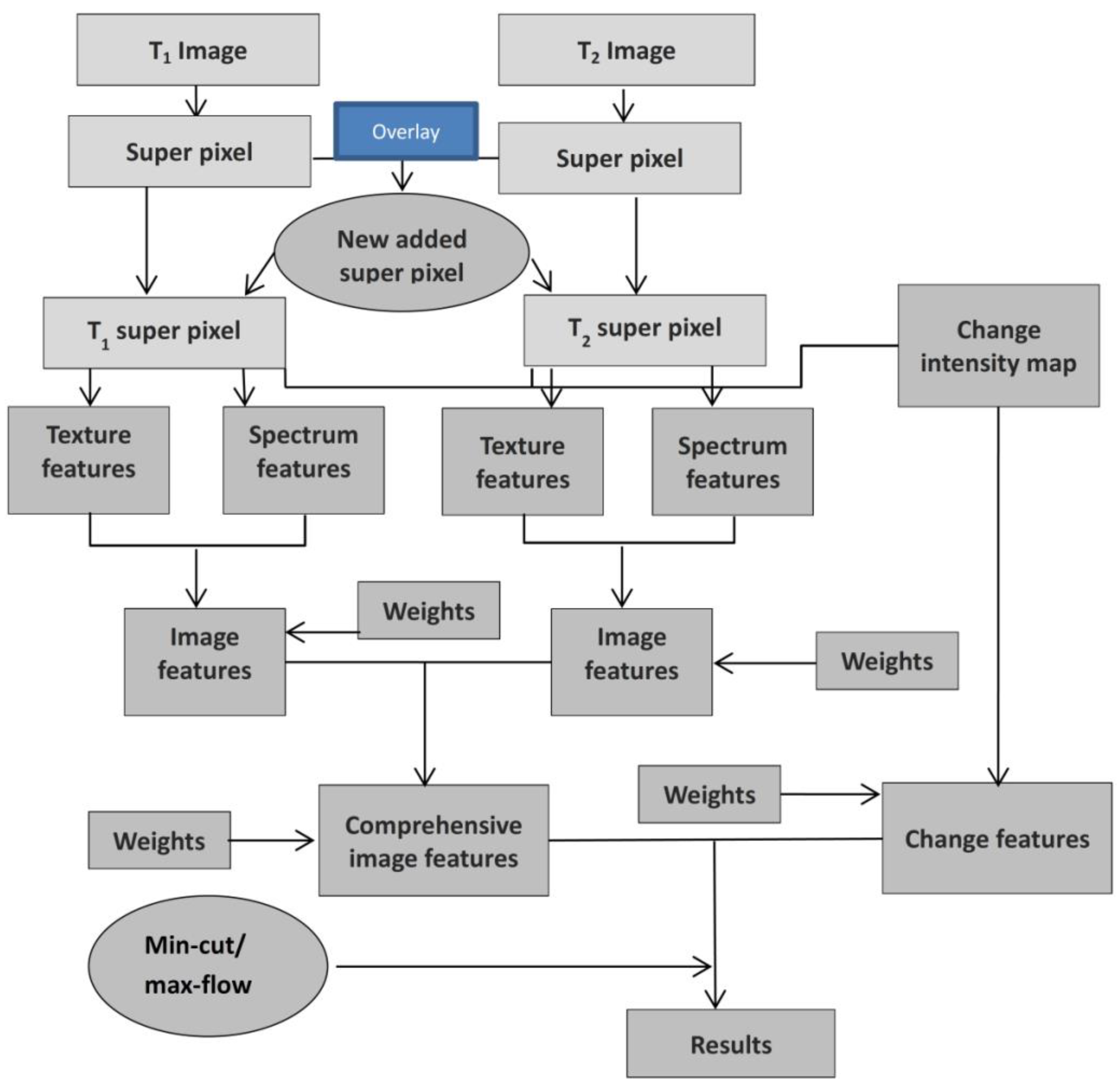
Figure 1 shows the flowchart of this study. It mainly includes four parts:
(1) Preprocessing step, which is presented in detail in Section 2.2.
(2) Superpixel segmentation and superposition analysis. After preprocessing, the T1 and T2 bitemporal images were transformed into superpixels by SLIC segmentation, and the bitemporal superpixels were overlaid to carry out the superposition analysis. This step is further discussed in Section 2.3.
(3) Construction of change detection energy function. After superposition analysis, new superpixels were added to T1 and T2 superpixels, and then the texture and spectral features were extracted from each superpixel to form the image feature of the energy function. On the other hand, a change intensity map was obtained via change vector (CV) calculation to form the change feature of the energy function. This step is illustrated in Section 2.4.
(4) Minimum cut/maximum flow cosegmentation. Superpixel-based cosegmentation is discussed in Section 2.5.

2.2. Preprocessing

All the operations in the preprocessing step of this study were conducted using ENVI software 5.3, and they included three parts:
(1) Geometric correction. For change detection tasks, multitemporal image registration, which aligns images of the same scene, is essential. The satellite images were all level 1 images and underwent preliminary geometric correction. However, misregistration is inevitable for multitemporal images [1]. A certain degree of geometric deviation and deformation is found between multitemporal images. In this study, the common method of selecting some control points was used for the registration of two images to ensure that the error was less than one pixel.
(2) Fast line-of-sight atmospheric analysis of hypercubes (FLAASH) atmospheric correction. The first step of atmospheric correction for the original image was radiometric calibration. Radiometric calibration was applied to eliminate or correct the image distortion caused by radiometric error.
(3) Relative atmospheric correction. In addition to FLAASH atmospheric correction, relative atmospheric correction was required for the image. This condition is mainly because sometimes images used in change detection are acquired with different sensors onboard, resulting in a large difference in spectral values between the images. Thus, conducting linear correction is necessary to prevent the effect on the results. A linear relationship is found between the gray values of images of different phases in the same region [38]. The key to linear correction is to determine the gain and offset parameters. An appropriate ground object sample point was selected from the two-phase images, and then the spectral value of the sample point was used to calculate the two parameters.

2.3. Superpixel Segmentation and Superposition Analysis

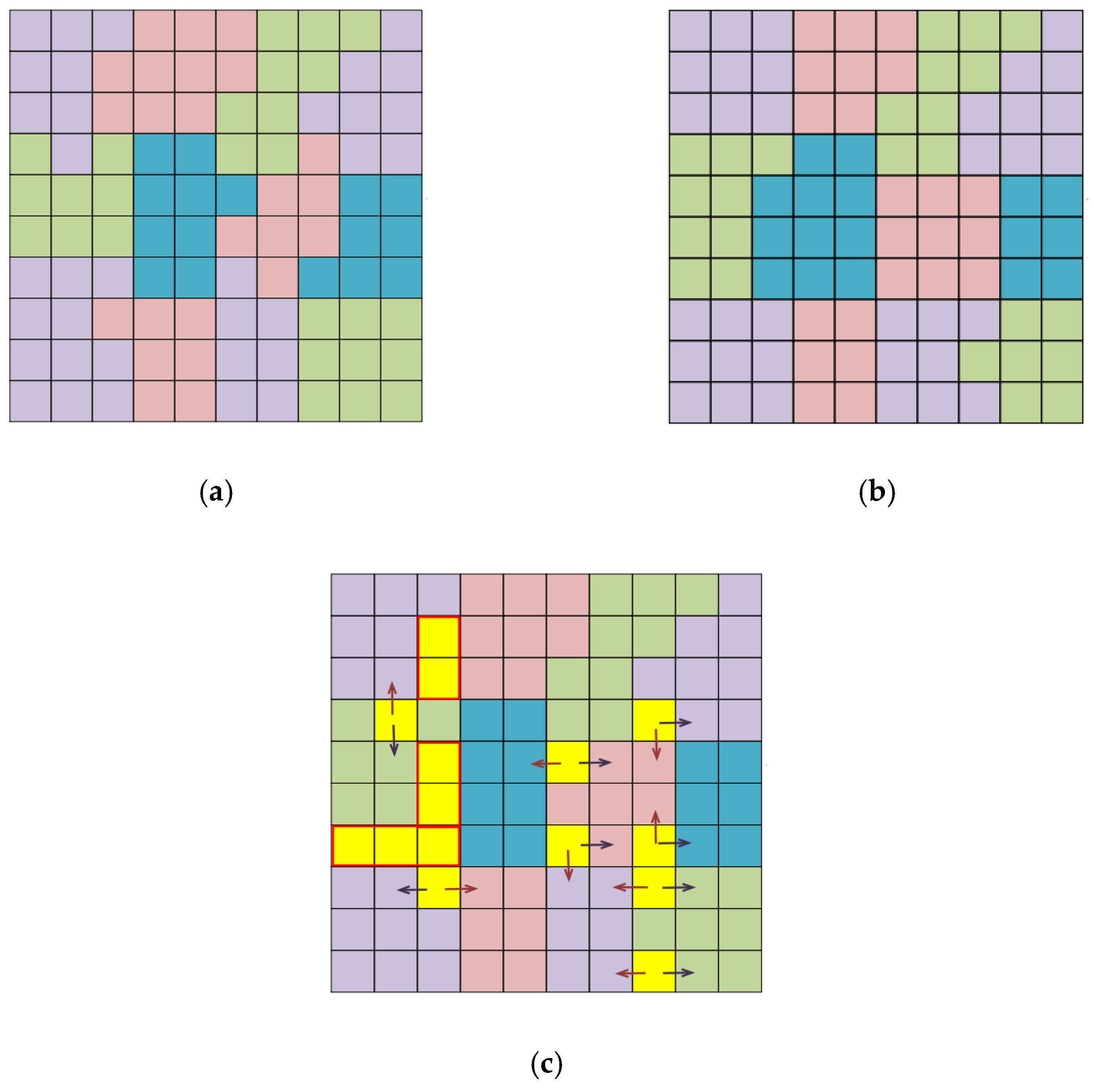
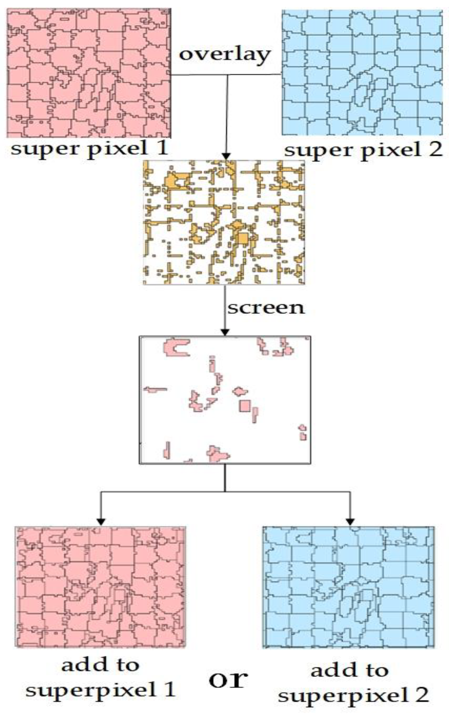
After preprocessing, the original image of different time phases in the same region can be segmented with SLIC superpixel segmentation. Although the number of superpixels in the two-time phase image after SLIC superpixel segmentation is the same, the boundaries of corresponding superpixels cannot align with each other due to the difference in spectral and texture feature distribution of images of different phases. The next step of cosegmentation can be conducted only when the two-time superpixel images are adjusted to a consistent boundary. Separating the inconsistent parts as new superpixels is needed. Superpixel images of two phases are superimposed to extract the inconsistent parts, and the superpixel boundary is adjusted to obtain a unified comprehensive superpixel segmentation boundary. The process of superpixel overlay is shown in Figure 2. The superpixel patches of two-phase images contain different boundaries. Two-phase superpixel images are overlaid to extract the inconsistent parts. Most of the extracted patches are interference patches of only one pixel size located at the boundary of the superpixel. This condition is mainly caused by the deviation of one to half a pixel of the two-phase image. Therefore, the screening condition related to patches of 1 pixel size being interfering patches is removed. The interfering pixels need to be returned to the corresponding images for reconstituting the boundary of the superpixel. Figure 3 illustrates the stacking process more clearly. Figure 3a,b represent the two-phase superpixel images, where different color patches represent different superpixel patches. They are superimposed to extract Figure 3c, where the yellow patches represent the extracted inconsistent pixels. As shown in Figure 3c, the interfering patches can be merged into a phase 1 superpixel image (illustrated by the red arrow) or phase 2 superpixel image (illustrated by the blue arrow). Different merges result in different superpixel boundaries. Therefore, the criterion for judging is that the closer the interference pixel is to the average gray value of the superpixel to be merged, the more proper it can be merged into the superpixel image of that time phase. The remaining inconsistent patches (the three yellow patches with a red frame in Figure 3c) are added to the superpixel set after merging the interfering pixels.
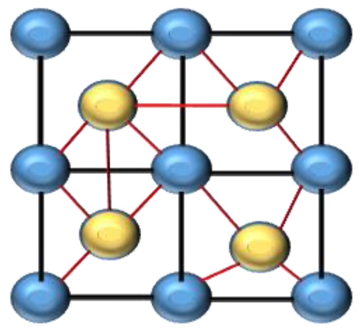
The neighborhood relationship between the original superpixels in the network flow diagram is disrupted due to the addition of some new superpixels after the superposition analysis. The locations of these new superpixels are random and irregular. Thus, establishing the neighborhood relationship for them is necessary (a four-neighborhood relationship was adopted in this study). As shown in Figure 4, the blue points represent the original superpixels, yellow points represent the newly added superpixels, red edges represent the adjacency relationship between the new superpixels and surrounding superpixels, and black edges represent the adjacency relationship between the existing original superpixels. The neighborhood relationship of the original blue superpixels is established. Thus, the neighborhood relationship of the new yellow superpixels is required to be determined. The four-neighborhood relationship in this study involved finding the four closest superpixels by calculating the shortest centroid distance between the superpixel blocks. In this way, the newly added superpixels could be incorporated into the original network flow diagram.
After the establishment of the neighborhood relationship of superpixels, the subsequent cosegmentation change detection is roughly the same as the previous pixel-based cosegmentation method [6], except that the superpixel is used as the node of the network flow diagram. The main steps and processes are briefly described in the sections below.

2.4. Construction of Energy Functions

The energy function consists of two parts, namely, change feature and image feature items, and is shown in Equation (1).
E = λ E 1 + E 2 ,
where E 1 is the change feature item, E 2 is the image feature item, and λ is the weight of the change feature item used to balance the proportion of the image feature and the change feature in the formula.
Change feature item E 1 is based on the change intensity map, which is obtained by calculating the CV value of each pixel. The probability that each pixel becomes the background (bkg) or object (obj-change area) is then assigned [27].
The image features of a single image are composed of two parts: spectral and texture features. Each image has different image features; thus, each image feature produces the corresponding results of cosegmentation change detection [26]. This study constructs a comprehensive image feature E 2 to obtain a unique result. Thus, the algorithm produces only one change detection result of cosegmentation.
The detailed process of energy function construction can be found in [27]. The superpixel is used to replace the original pixel after the construction of the energy function of each pixel. The image and change features of all pixels in the superpixel block are averaged to obtain the image and change features of the superpixel.

2.5. Minimum Cut/Maximum Flow Algorithm Based on Superpixel

Cosegmentation is the optimization of the energy function to achieve the final image segmentation, and the optimization of the energy function is achieved by obtaining the minimum cut of the network flow diagram. The minimum cut/maximum flow algorithm is used as the energy function optimization method. The superpixel image should be transformed into the network flow diagram. The construction of the network flow diagram is as follows: each superpixel is set as a node, and two special nodes S (object) and T (background) are set. The nodes are connected by edges. Two special nodes are connected to each superpixel node, which are the edges (S, P) and (P, T). Superpixel node P is connected to adjacent superpixel node Q (in four adjacent neighbors), and the edge (P, Q) is constructed. The change feature item is used as the edge weight between the two special nodes and the superpixel node, which is called the t-connection. The image feature item is regarded as the edge weight of the two superpixel nodes, which is called the n-connection. At this point, the network flow diagram of superpixel construction is completed.
According to the Ford and Fulkerson theorem [8], the maximum flow value in the network flow diagram is equal to the capacity of the minimum cut. Equation (2) expresses the minimum cut.
c u t = P V 1 , Q V 2 w ( P , Q ) ,
where cut is the minimum cut set, that is, the set of edges with the minimum weight in the graph. w(P, Q) represents the edge between superpixels P and Q with the minimum weight. If V 1 and V 2 are subsets of ordinary nodes belonging to object and background, respectively, then the edge between superpixel nodes P and Q belongs to two different subsets P V 1 and Q V 2 in the network flow graph with the minimum weight. This edge can be divided into the minimum cut set. The edges of all the minimum cut sets in the graph are found and broken. Each superpixel is classified into V 1 or V 2 . The superpixel in the V 1 subset is assigned as the change region, and the V 2 subset is assigned as the no change region.
In this study, the method to calculate the graph’s maximum flow used by Xie [27] was followed, and Dinic’s algorithm [39] was used to obtain the minimum cut set of the graph.

3. Results

3.1. Study Areas

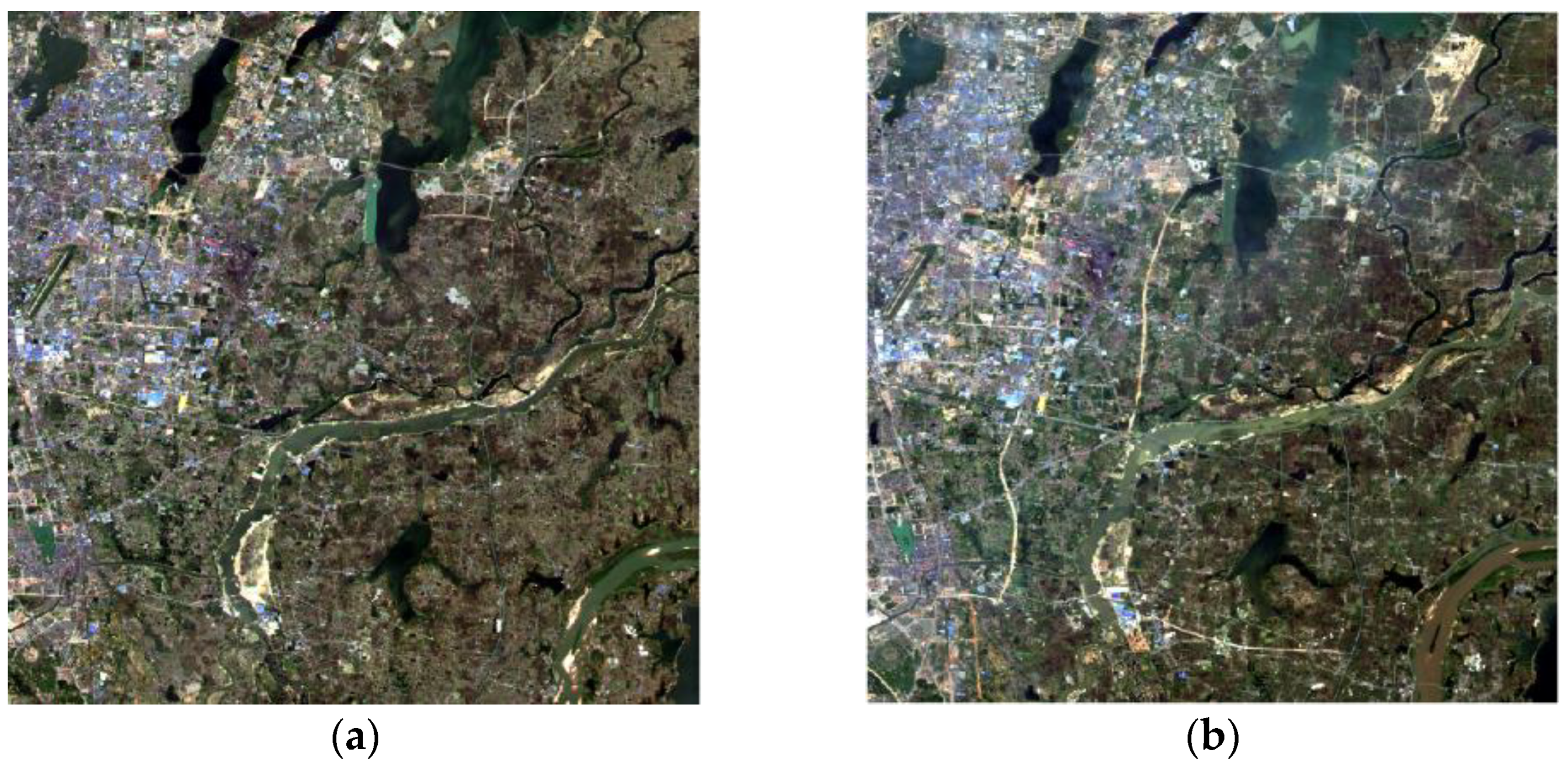
Two study areas with different resolution satellite images were used to test the applicability of the proposed algorithm. The Chinese GF-1 satellite wide field view (WFV) image of Nanchang County, Jiangxi Province, China was selected as one of the test areas in this study (Figure 5). The spatial resolution of the GF-1 WFV image is 16 m, and the image has four bands, which are blue, green, and red visible bands and a near-infrared band. Nanchang County is located between 28°16′ and 28°58′ north (N) latitude and 115°49′ and 116°19′ east (E) longitude, covering an area of approximately 1810.7 km2. The image size of the experimental area selected in this study was 1350 × 1350 pixels, and the acquisition dates of the two-phase images were 14 April 2015 (Figure 5a) and 29 April 2017 (Figure 5b). True color (red, green, and blue bands) was adopted for the composite display of the two images. The two-phase images of the same month and different years were selected to effectively avoid the changes in surface vegetation caused by seasonal changes, thereby reducing the detection of spurious changes.
From the visual interpretation of the images, the main land-cover types were grassland, cultivated land, shrub land, water body, artificial cover, and bare land. The main changes in the experimental area were the increase in artificial cover and uncompleted bare land caused by human activities and the change in water body caused by pollution.
In the second study area, Landsat images of Jackson, Mississippi, United States were selected (Figure 6). The image size of the study area was 1200 × 1200 pixels. The acquisition dates of the two-phase images were 17 September 2000 and 5 September 2010. The year 2000 TM images were acquired by the Landsat-7 satellite with eight bands, and the year 2010 TM images were acquired by the Landsat-8 satellite with a total of 11 bands, both at a spatial resolution of 30 m.
A visual interpretation of the study area in the United States showed no large-scale change in this area. The main changes were the artificial cover and the conversion between forest grassland and shrub in a small area.

3.2. Superpixel Segmentation Results

Two parameters, namely, compactness m and segmentation step size S, need to be set in SLIC superpixel segmentation [17]. The variable m is introduced to allow controlling the compactness of a superpixel. The greater the value of m, the more spatial proximity is emphasized and the more compact the cluster. The range of m can be within 10–40 with a step of 10 according to [17]. The variable S is the segmentation step size. Since, in SLIC segmentation, the spatial extent of any superpixel is approximately S2, the minimum value of S was 3, which represented that the size of the super pixel was about 3 × 3 pixels. In this study, multiple experiments were conducted to determine the optimal value of the two parameters.
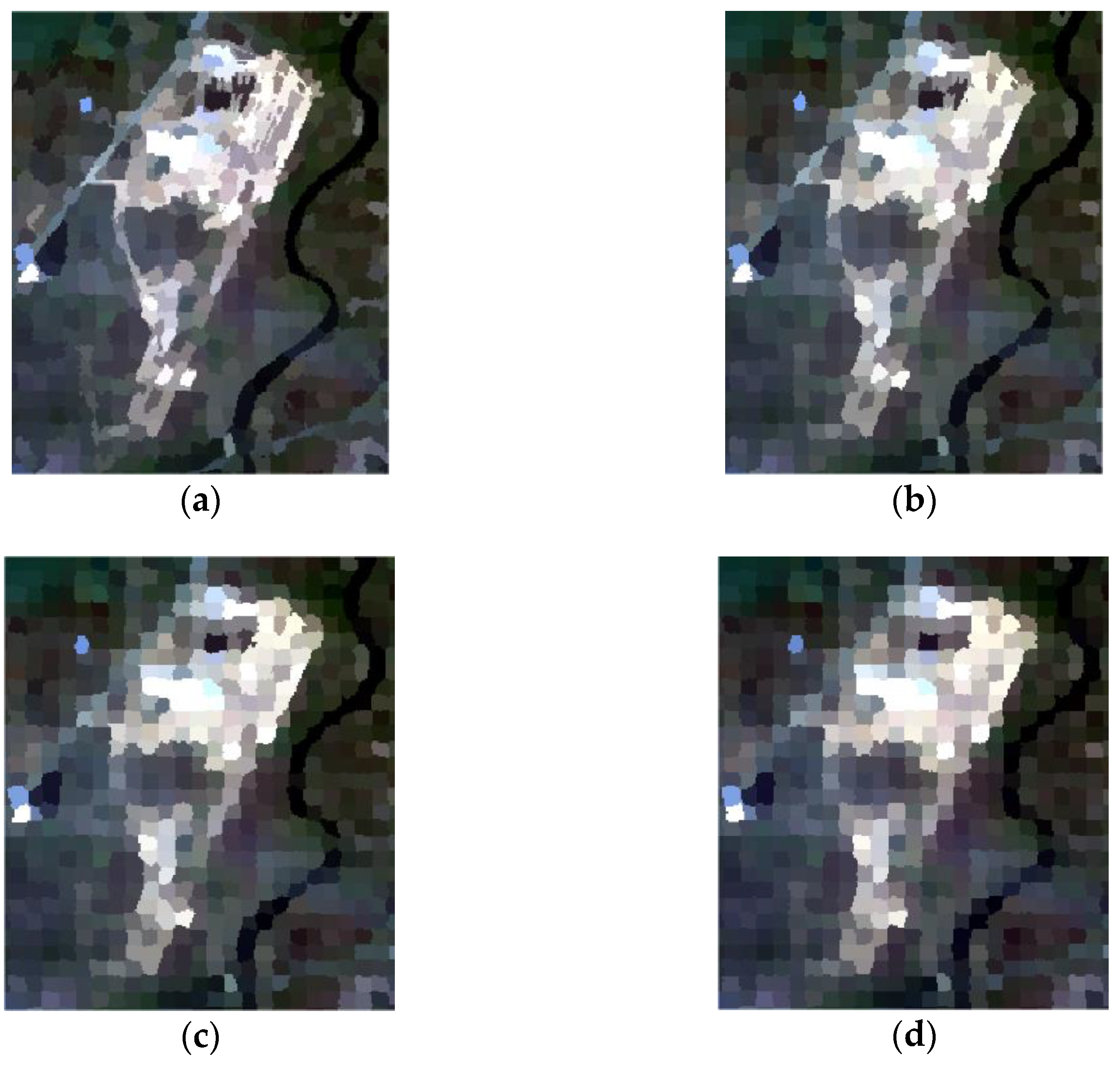
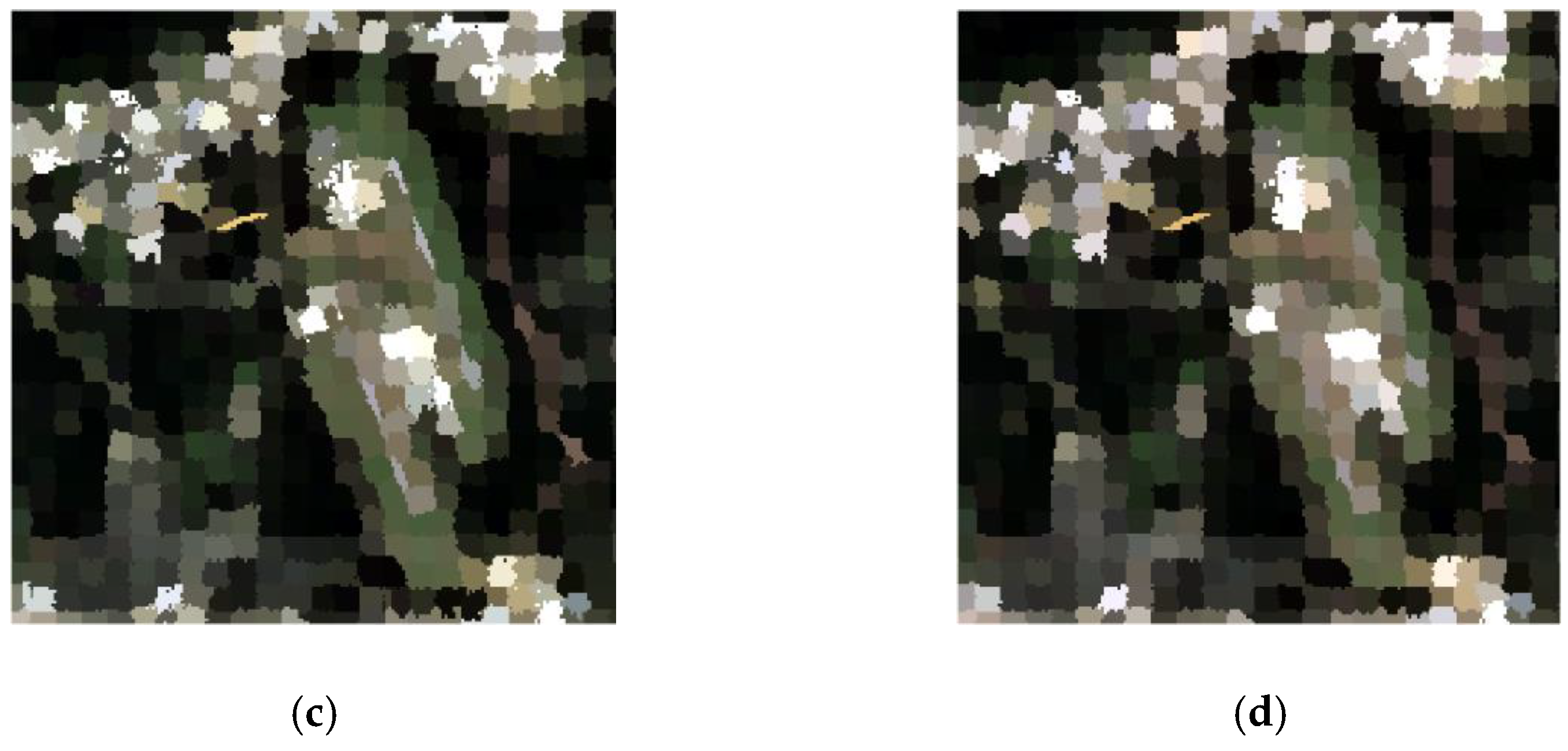
All of the four possible values (10, 20, 30, and 40) of compactness parameter m were set to conduct experiments. The results are shown in Figure 7 and Figure 8.
As shown in Figure 7 and Figure 8, the larger the m value, the less fine the segmentation result, and the edge of the superpixel did not fit the original image object. The shape or texture of the object disappeared with the increase in m. On the contrary, the smaller the m value, the more the superpixel segmented edge fit the object. This condition could better retain the feature information of the object in the image.
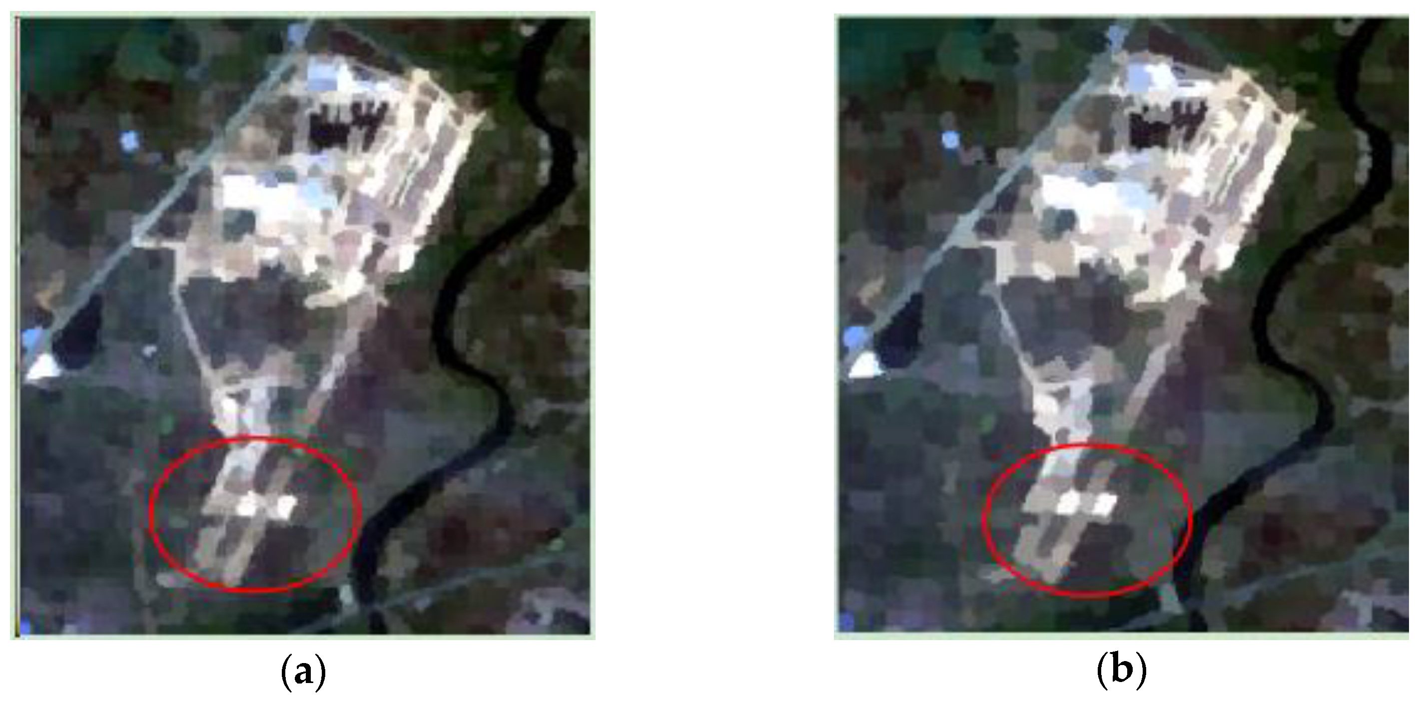
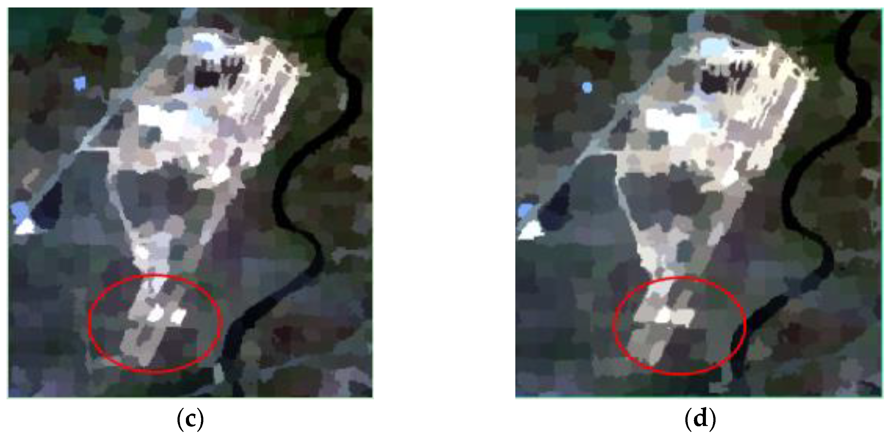
As mentioned above, step length S is another parameter used in superpixel segmentation. It affects the subsequent segmentation change detection speed and accuracy of the result. If S is one pixel size, the change detection is carried out on a pixel level and the speed of the algorithm cannot be improved, On the contrary, if S is extremely large, the speed of the algorithm increases but the accuracy of the results reduces. In this study, considering that the purpose of superpixel segmentation is to reduce the number of primitives in the network flow diagram, the minimum value of S (S = 3) was discarded. Because S must be a singular number, the experiment started from 5, and superpixel step sizes S of 5, 7, 9, and 11 were evaluated in the test areas. This process was performed to determine the optimal superpixel segmentation step size for final change detection. Figure 9 and Figure 10 show the results of superpixel segmentation with different values of S in the test areas.
As shown in the part marked by a red circle in Figure 9 and Figure 10, the superpixel obtained in the two test areas was mainly consistent with the original contour of the ground object and was compact and uniform when the superpixel step length S was 5, 7, or 9. This finding could simplify the image information whilst retaining the basic features of the ground object in the image to a great extent. However, the generated image was relatively fuzzy when the superpixel step length S is 11, regardless of whether the image had high resolution or low-to-medium resolution. This image could not completely present the original shape and texture of the ground objects, and some linear ground objects were blurred, making it indiscernible. On the contrary when the step size was 5, the ground objects were extremely detailed, and the ground objects presented a phenomenon of oversegmentation. Considering that the step size is inversely proportional to the running time, the best step size was selected to be 7 or 9.

3.3. Results of Cosegmentation Change Detection Based on Superpixels

Figure 11 shows the final change detection results in the study areas on the basis of superpixels with a superpixel segmentation step size S of 9 and compactness m of 10.
Table 1 shows the comparison of the overall accuracy, kappa coefficient, and running time of change detection results in Figure 11. The overall accuracy of the GF-1 image was 0.860, and its kappa coefficient was 0.724. The overall accuracy of the Landsat image was 0.785, and its kappa coefficient was 0.570. The detection accuracy of the GF-1 image was higher than that of the Landsat image. The higher-resolution image showed better adaptability when two images of different spatial resolutions had the same segmentation step value. This is because more mixed pixels can be found in low-to-medium resolution images than high-resolution ones. On this basis, using superpixels to simplify image information causes information loss and reduces the accuracy of change detection results.
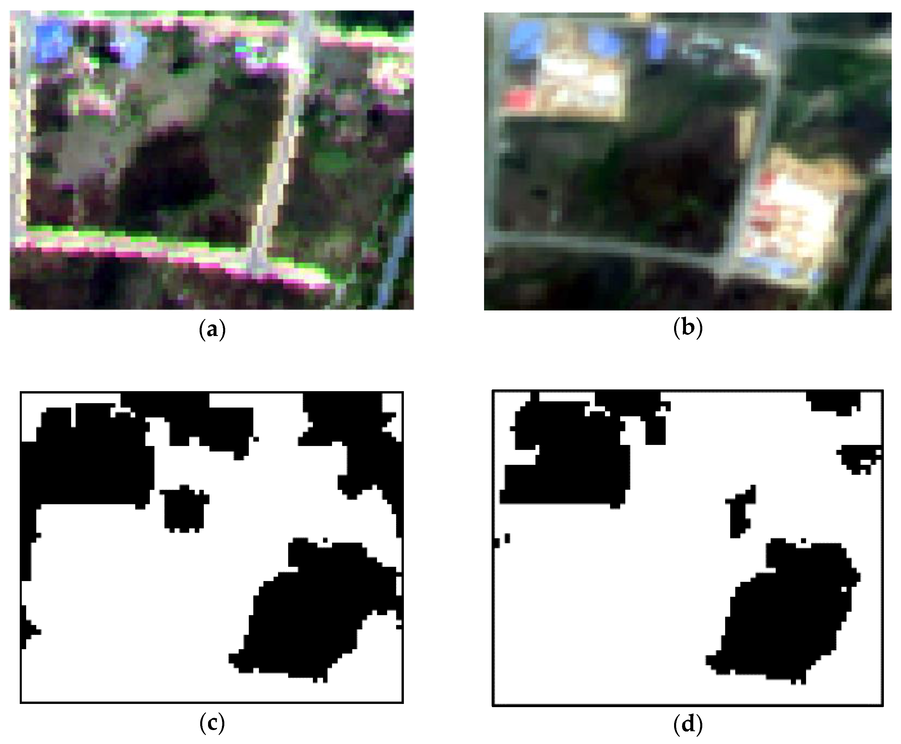
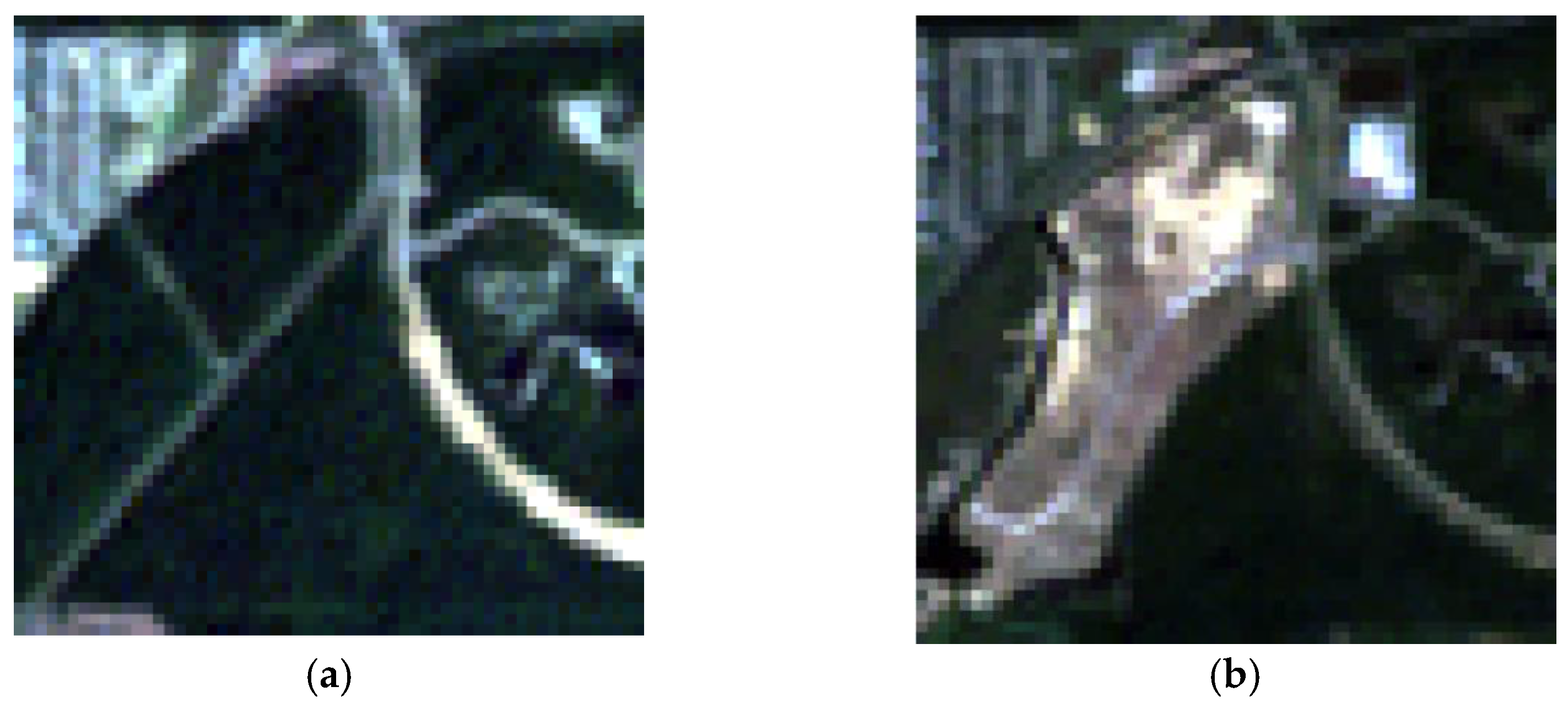
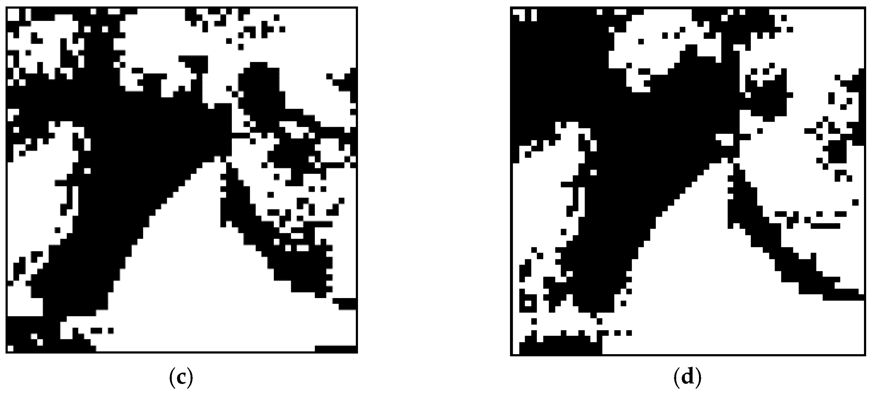
A comparative experiment was conducted to verify the validity of the superpixel superposition analysis in Section 3.2. Analysis areas were selected from the study areas to facilitate detailed analysis, as shown in Figure 12 and Figure 13. The detection result for stacking two-phase superpixels in overlay analysis was better, that is, the result was in line with the original changing surface boundary. The boundary of change detection results without stacking analysis showed that the detected change target did not fit the boundary of the real ground object, and some small changes were ignored, resulting in a decrease in accuracy. The addition of superposition analysis allowed extracting the parts with different geometric shapes of two-phase images and adding them into the image as separate superpixels. This process can avoid the problems of missing and false detection of the ground object boundary to a certain extent.

3.4. Comparison with Other Change Detection Methods

This research compared three methods, namely, pixel-based change detection, object-based change detection, and pixel-level cosegmentation, to test the effect of the cosegmentation algorithm based on superpixels.

3.4.1. Pixel-Based Change Detection

The normalized difference vegetation index (NDVI) is obtained by the ratio method of combined red and near-infrared bands. This index is less affected by topography and radiation and can reflect the change trend of surface vegetation coverage. NDVI is used as the characteristic index to detect change information, and the calculation formula is shown in Equation (3).
NDVI = B N I R B R B N I R + B R ,
where BNIR is the near-infrared band reflectance, BR is the red band reflectance, and the range of the NDVI value is (−1, 1). The difference between the two-phase NDVI values is obtained using Equation (4).
dNDVI = N D V I t 1 N D V I t 2 ,
where N D V I t 1 is the NDVI value of the phase 1 image, and N D V I t 2 is the NDVI value of the phase 2 image. The threshold of dNDVI was obtained by using a histogram-based method (Otsu’s method; Otsu 1979) to obtain the optimal value automatically. Pixel-based change detection was completed using the Image Change Workflow tool in ENVI software 5.3.
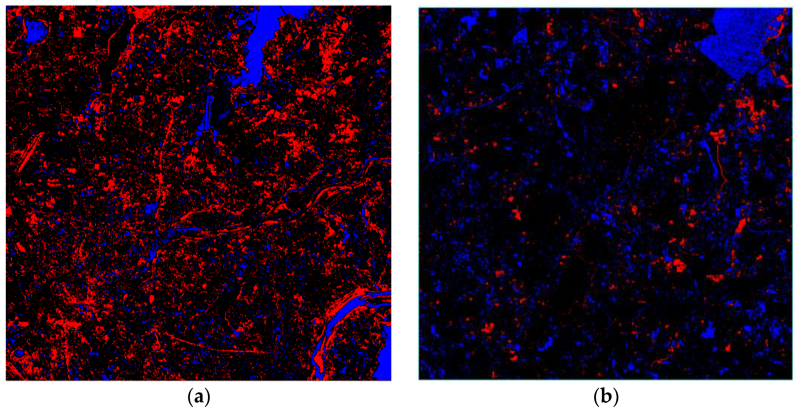
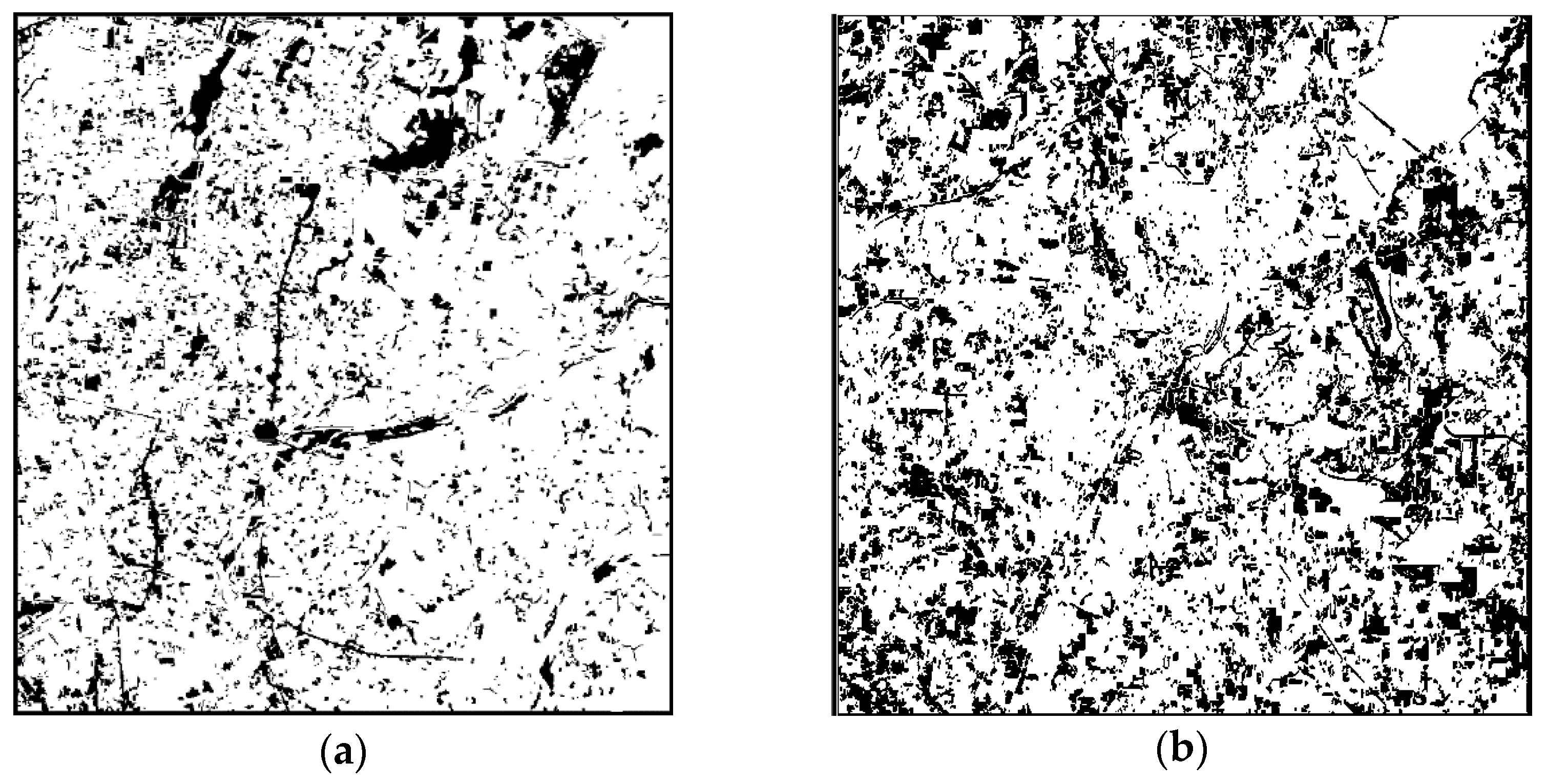
In Figure 14, the black part remained unchanged, whereas the blue and red parts were changed regions. The blue region represents the increase in NDVI value, that is, the increase in vegetation in this region, and the red region represents the decrease in vegetation in this region. From the detection results, the changes detected by the pixel-based method were scattered fragmented pixels distributed throughout the whole image. As shown in Figure 14a, the water body remained unchanged but a large number of changes were extracted. On the contrary, the cosegmentation results were less affected by “same object different spectrum, foreign body same spectrum” than the pixel-based results.
Table 2 and Table 3 show the results of accuracy evaluation using a confusion matrix. In this study, a certain number of sample points in the study area were selected as the evaluation criteria by using the visual interpretation of the Google Earth image. A total of 365 sample pixels were selected from the GF-1 image, with 177 changed samples and 188 unchanged samples. A total of 525 pixel sample points were selected in Landsat images, including 264 changed samples and 261 unchanged samples. The result accuracy for Landsat images was higher than that for GF-1 images. This was mainly due to the poor quality of the GF-1 image.

3.4.2. Object-Based Change Detection

The object-based change detection experiment was conducted through the multiscale segmentation of eCognition Developer 9 (Trimble Geospatial, Munich, Germany). The multiscale composite segmentation of two-time phase images was performed through multitime combination segmentation. The shape factor and tightness factor were set to 0.1 and 0.5, respectively. The image objects with the same segmentation boundary were obtained and used as the basic processing unit for change detection.
Multiscale segmentation was combined with the two-time phase image. The segmentation results were affected by the two-time phase image, and the integrity of the segmented objects could not be guaranteed, making it difficult to determine the optimal segmentation scale. The segmentation scale was set to a small value of 10 to ensure the integrity of the object to a certain extent.
CV was used as the feature index to extract the change image patches after the image was segmented into objects. The calculation formula of CV is as follows:
CV = k = 1 n ( B p k ( t 1 ) B p k ( t 2 ) ) 2 ,
where B p k ( t 1 ) represents the spectral value of image object p in the band k of t 1 phase, and B p k ( t 2 ) represents the spectral value of image object p in the band k of t 2 phase. K = 1, 2, …, n, where n represents the total number of image bands.
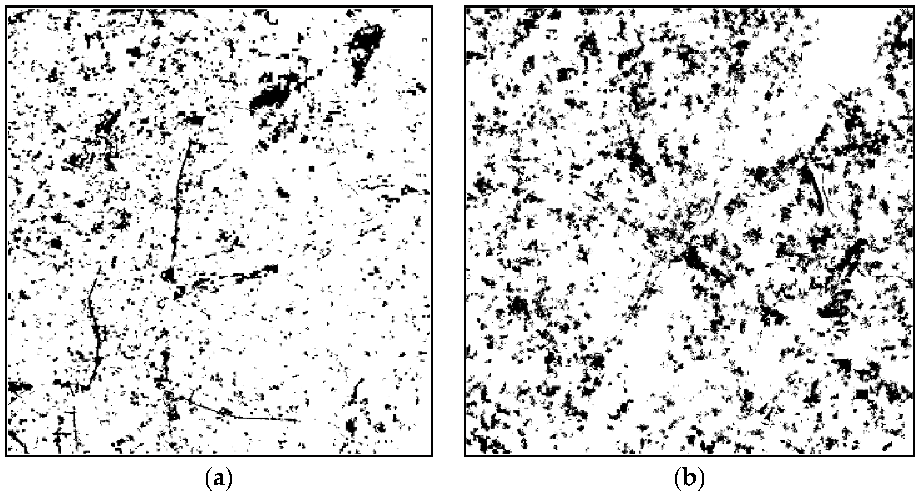
In accordance with the test results, the overall accuracy and Kappa coefficient of the test results were optimal when the threshold value of CV was set as CV > µ + 0.1σ, where µ is the mean value of CV of all objects, and σ is the standard deviation. In Figure 15, the black part represents the changed patches, and the white part represents the unchanged area. Compared with pixel-based change detection, the scattered changed pixels were eliminated, and the change in water area decreased considerably. Table 4 and Table 5 show the results of object-based change detection accuracy of GF-1 and Landsat imagery respectively.

3.4.3. Change Detection of Pixel-Level Cosegmentation

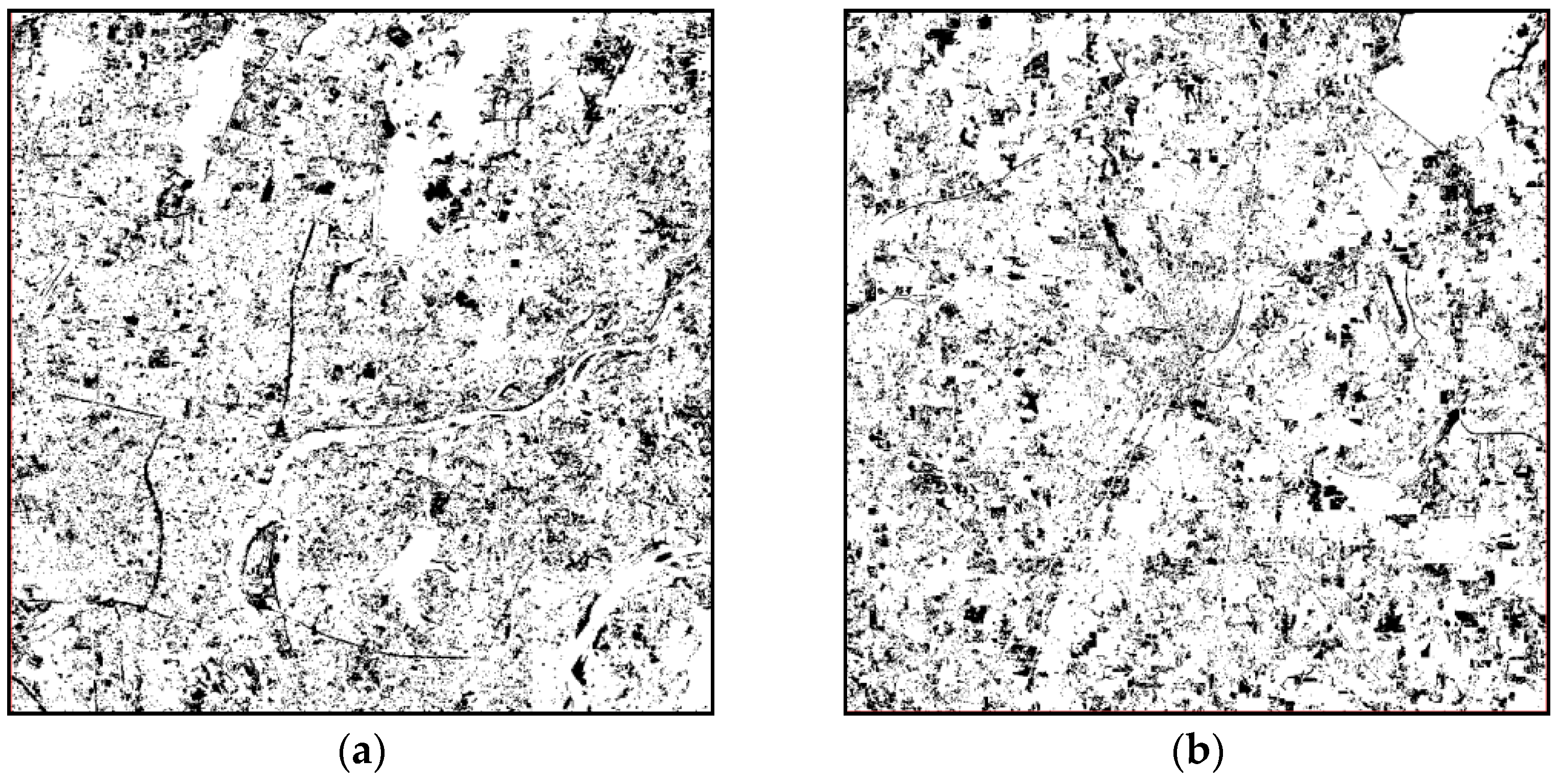
The change detection method of pixel-level cosegmentation cannot process the image of the whole study area at one time due to the limitation of computation efficiency. Therefore, the image of the study area was divided into several small images of 150 × 150 pixels. The parfor parallel processing statement in MATLAB 2016a was used to perform multithreaded parallel computation on the small images, and the small images were stitched together.
Figure 16 shows the results of change detection based on cosegmentation and Table 6 and Table 7 are the results of accuracy assessment of GF-1 and Landsat imagery respectively The black part represents the change patches, and the white part represents the unchanged area. The change patches detected by pixel-level cosegmentation could reflect the patchy property, and the result was better than the pixel-based detection method. Although the integrity of the image patches was lower than that of the object-based detection method, the accuracy was similar by comparing Table 4 and Table 5. Pixel-level cosegmentation solves the difficult selection of segmentation scale. However, the crucial shortcoming of this method is that it cannot directly process a large image, and the whole process takes an extremely long time, thereby making the detection method based on pixel-level cosegmentation impractical.

4. Discussion

Table 8 compares the accuracy of four change detection methods, i.e., pixel-based, object-based, pixel-level, and superpixel cosegmentation. The accuracy of the superpixel-based method for the medium- and low-resolution image, that is, the Landsat image, reduced from 0.887 to 0.785. This was mainly because the superpixel constructed by this method causes the information loss of medium- and low-resolution images, resulting in a decrease in accuracy. However, high-resolution images have minimal influence on the information loss of such images. On the contrary, they ignore some scattered noises and spurious changes. Thus, the accuracy is improved. Therefore, in this experiment, the superpixel cosegmentation change detection method was more suitable for images with a high resolution, whereas it was less suitable for images with a resolution of 30 m or lower.
The pixel-based detection method only considers the spectral value of a single pixel and simply performs the calculation between pixels without considering the spatial relationship between adjacent pixels. Therefore, the image patches extracted by this method are extremely scattered and vulnerable to image noise, with low accuracy. The object-based detection method combines adjacent pixels with homogeneity as the object for change detection. Although the detected image patches are reliable and the accuracy is greatly improved, this method relies on the selection of the best segmentation scale. The cosegmentation and superpixel cosegmentation change detection methods improve this shortcoming and ensure that the accuracy of the detection results is similar to that of the object-based method. However, cosegmentation and superpixel cosegmentation methods are relatively different in terms of operational efficiency. Table 9 compares the computing efficiency of the two methods in detail according to four aspects, namely, running time, whether to cut the image into small blocks, number of fragmentary image patches, and accuracy.
The operating time of superpixel cosegmentation in Table 9 was about 4–5 h, and the corresponding pixel-level cosegmentation took more than 24 h. The operations were conducted with the same computer using the same hardware facilities and operating environment. The configuration of the computer was as follows: Intel(R) Xeon(R) central processing unit (CPU) E5-1620 V4. @ 3.50 GHz; memory 16 GB; 64-bit operating system.
The detection method based on cosegmentation has extremely low computational efficiency and is inconvenient to calculate the large sized image. Thus, the image needs to be partitioned for processing. The overall accuracy of the two methods was similar, but the computational efficiency was improved by many times. Compared with the detection results, the number of scattered image patches (2 × 2 pixels and smaller pixel patch) in the detection results shows that the number of scattered image patches based on the cosegmentation method was significantly higher than that based on the superpixel method. Although this condition had minimal effect on the accuracy of the results, it still affected the region of the image spots. Thus, the proposed superpixel-based cosegmentation change detection method can improve the efficiency of cosegmentation change detection and ensure the accuracy of detection results. Fewer scattered noise patches are found in the detection results, and the obtained results have better integrity.

5. Conclusions

In this study, a superpixel cosegmentation change detection method was developed to improve the cosegmentation change detection method due to its low efficiency. The introduction of superpixels greatly improved the operation rate of cosegmentation change detection and expanded the size of images that can be processed. The accuracy of change detection results could be kept at approximately 0.8.
The SLIC superpixel segmentation algorithm was integrated into the cosegmentation change detection algorithm. As the first step of the algorithm, multitemporal images were segmented to superpixels. The optimal values of two important parameters in superpixel segmentation were determined (compactness and segmentation step size) by conducting experiments on two experimental images with different spatial resolutions. The superpixel images of multiple phases were superpositioned to extract the different parts as new superpixels. A cosegmentation change detection energy function based on superpixels was constructed and divided into two terms: change feature and image feature items. The two feature terms were calculated with superpixels as the basic unit. Each superpixel was taken as the node to construct the network flow diagram, and the change and image features in the energy function were taken as the weight values of the formation edges in the network flow diagram. The neighborhood relationship between the superpixel nodes in the network flow diagram was obtained by calculating the distance between the centroid of the superpixel and then selecting the shortest four centroid distances as the neighborhood relationship of the current superpixel. The accuracy of the experimental results based on pixel, object, and cosegmentation were evaluated and compared with each other using a confusion matrix. The advantages and disadvantages of the four methods were summarized.
The proposed superpixel cosegmentation change detection method overcame the shortcomings of the cosegmentation change detection method and obtained good results. However, this method has some shortcomings and deficiencies to be improved.
(1) At present, the execution time of the superpixel cosegmentation change detection algorithm is still long. The current algorithm was naïvely coded without any optimization. The two main factors that restrict the execution speed of the algorithm are the algorithm itself and the serial execution mode. The algorithm efficiency can be improved by graphics processing unit (GPU) parallel calculation. Analyzing each step of the algorithm is necessary. For example, in the process of cosegmentation, the calculation of the image features of the T1 image and T2 image is independent. For this task, dual GPUs can be used to speed up the process, where each GPU is responsible for the calculation of one image features. Moreover, the calculation process of each superpixel can be mapped to a thread and then assigned to a stream processor for processing. In this way, a large number of GPU stream processors can be used to achieve large-scale thread parallelism to compress time. In addition to parallel processing, the appropriate data structure can be selected to reduce the nesting of the loop in the code to reduce the computational time complexity and spatial complexity of the cosegmentation method.
(2) The applicability of this method decreases with the decrease in the spatial resolution of the image. In this study, this method was less suitable for images with a spatial resolution of 30 m or lower, whereas it was more suitable for images with a spatial resolution of 16 m or higher. The specific scope of application needs to be further studied and determined. Improving the algorithm and expanding its application scope are necessary.
(3) The change feature item of the energy function is still imperfect. The superpixels are used as the basic processing unit, but only the spectrum value is considered. Thus, the result is influenced by the “same objects with different spectra, different objects with the same spectrum” phenomenon. The change feature item of the energy function largely influences the results. A suitable and efficient algorithm needs to be developed.
(4) A lot of information can be mined from a superpixel image. These features include the NDVI and normalized water index, texture feature, shape feature, and superpixel spatial relationship. These features can be added to the energy function of image features or as a new feature in segmentation for improving the accuracy of results.
(5) Remote sensing (RS) images reflect only the instantaneous state of the Earth’s surface according to the sampling period. The “same objects with different spectra, different objects with the same spectrum” phenomenon and seasonal phase lead to interference. Consequently, the outcome of change detection will include spurious changes. Several studies [40] demonstrated that, through integrating the auxiliary information with the RS images, more accurate changing results are obtained. The change information obtained from the images is only the initial result, and further processing combined with other multisource knowledge is needed to obtain satisfactory results.
This paper was concerned with the change detection of paired images at different time points. At present, remote sensing time series analysis has become a hot research field. Cosegmentation as a weakly supervised segmentation method can simultaneously segment multiple images of common interest. In the future, it can be used to extract time series image changes and more efficiently analyze the trend of land-cover changes.
Author Contributions

Conceptualization, funding acquisition and methodology, L.Z.; data curation, methodology and writing—original draft, J.Z.; methodology and software, Y.S. All authors have read and agreed to the published version of the manuscript.

Funding

This work was funded by The National Key Research and Development Program of China under Grant (NO.2016YFB0501404) Institutional.

Institutional Review Board Statement

Not applicable.

Informed Consent Statement

Not applicable.

Data Availability Statement

The data presented in this study are available on request from the corresponding author.

Conflicts of Interest

The authors declare no conflict of interest.

References

  1. Lambin, E.; Meyfroidt, P. Global land use change, economic globalization, and the looming land scarcity. Proc. Natl. Acad. Sci. USA 2011, 108, 3465–3472. [Google Scholar] [CrossRef] [Green Version]
  2. You, Y.; Cao, J.; Zhou, W. A Survey of Change Detection Methods Based on Remote Sensing Images for Multi-Source and Multi-Objective Scenarios. Remote Sens. 2020, 12, 2460. [Google Scholar] [CrossRef]
  3. Zhou, Z.; Ma, L.; Fu, T.; Zhang, G.; Li, M. Change Detection in Coral Reef Environment Using High-Resolution Images: Comparison of Object-Based and Pixel-Based Paradigms. Int. J. Geo-Inf. 2018, 7, 441. [Google Scholar] [CrossRef] [Green Version]
  4. Jin, X.Y. A Segmentation-Based Image Processing System. U.S. Patent 20090123070A1, 14 May 2007. [Google Scholar]
  5. Pare, S.; Kumar, A.; Singh, G.K.; Bajaj, V. Image Segmentation Using Multilevel Thresholding: A Research Review. Iran. J. Sci. Technol. Trans. Electr. Eng. 2019, 44, 1–29. [Google Scholar] [CrossRef]
  6. Baatz, M.; Schäpe, A. Multiresolution segmentation: An optimization approach for high quality multi-scale image segmentation. J. Photogramm. Remote Sens. 2000, 58, 12–23. [Google Scholar]
  7. Gaetano, R.; Masi, G.; Poggi, G.; Verdoliva, L.; Scarpa, G. Marker-controlled watershed-based segmentation of multiresolution remote sensing images. IEEE Trans. Geosci. Remote Sens. 2014, 53, 2987–3004. [Google Scholar] [CrossRef]
  8. Ciecholewski, M. River channel segmentation in polarimetric SAR images: Watershed transform combined with average contrast maximisation. Expert Syst. Appl. 2017, 82, 196–215. [Google Scholar] [CrossRef]
  9. Chen, G.B.; Sun, Z.W.; Zhang, L. Road Identification Algorithm for Remote Sensing Images Based on Wavelet Transform and Recursive Operator. IEEE Access 2020, 8. [Google Scholar] [CrossRef]
  10. Gonalves, J.; Pas, J.; Marcos, B.; Mücher, C.A.; Honrado, J.P. SegOptim-A new R package for optimizing object-based image analyses of high-spatial resolution remotely-sensed data. Int. J. Appl. Earth Obs. Geoinf. 2019, 76, 218–230. [Google Scholar] [CrossRef]
  11. Yang, D.; Lv, J.; Zhang, D.; Zhang, J.; Yuan, J. Extracting multi-features and optimizing feature space with sparse auto-encoder over WorldView-2 images. Int. J. Remote Sens. 2019, 40, 6418–6443. [Google Scholar] [CrossRef]
  12. Braga, A.M.; Marques, R.C.P.; Rodrigues, F.A.A.; Medeiros, F.N.S. A Median regularized level set for hierarchical segmentation of SAR images. IEEE Geosci. Remote Sens. Lett. 2017, 14, 1171–1175. [Google Scholar] [CrossRef]
  13. Jin, R.; Yin, J.; Wei, Z.; Jian, Y. Level Set Segmentation Algorithm for High-Resolution Polarimetric SAR Images Based on a Heterogeneous Clutter Model. IEEE J. Sel. Top. Appl. Earth Obs. Remote Sens. 2017, 10, 4565–4579. [Google Scholar] [CrossRef]
  14. Yuan, X.Y.; Shi, J.F.; Gu, L.C. A Review of Deep Learning Methods for Semantic Segmentation of Remote Sensing Imagery. Expert Syst. Appl. 2020, 169. [Google Scholar] [CrossRef]
  15. Hoeser, T.; Bachofer, F.; Kuenzer, C. Object Detection and Image Segmentation with Deep Learning on Earth Observation Data: A Review-Part II: Applications. Remote Sens. 2020, 12, 3053. [Google Scholar] [CrossRef]
  16. Niemeyer, I.; Marpu, P.R.; Nussbaum, S. Change detection using the object features. In Proceedings of the IEEE International Geoscience & Remote Sensing Symposium, Barcelona, Spain, 23–27 July 2007; pp. 91–106. [Google Scholar]
  17. Achanta, R.; Shaji, A.; Smith, K.; Lucchi, A.; Fua, P.; Süsstrunk, S. SLIC superpixels compared to state-of-the-art superpixel methods. IEEE Trans. Pattern Anal. Mach. Intell. 2012, 34, 2274–2282. [Google Scholar] [CrossRef] [PubMed] [Green Version]
  18. Hussain, H.; Chen, D.M.; Cheng, A.; Wei, H.; Stanley, D. Change detection from remotely sensed images: From pixel-based to object-based approaches. ISPRS J. Photogramm. Remote Sens. 2013, 80, 91–106. [Google Scholar] [CrossRef]
  19. Comaniciu, D.; Meer, P.J.I.T.P.A.; Intelligence, M. Mean Shift: A Robust Approach Toward Feature Space Analysis. IEEE Trans. Pattern Anal. Mach. Intell. 2002, 24, 603–619. [Google Scholar] [CrossRef] [Green Version]
  20. Huang, J.; Liu, Y.; Wang, M.; Zheng, Y.; Wang, J.; Ming, D. Change Detection of High Spatial Resolution Images Based on Region-Line Primitive Association Analysis and Evidence Fusion. Remote Sens. 2019, 11, 2484. [Google Scholar] [CrossRef] [Green Version]
  21. Ford, B.L.R., Jr.; Fulkerson, D.R. Flows in Networks; Mathematics of Computation; Princeton University Press: New York, NY, USA, 1962; pp. 319–331. [Google Scholar]
  22. Ma, X.; Liu, X.; Gao, Y.X.; Jin, X.L. A Review of Cooperative Image Segmentation Methods. J. Comput. Aided Des. Graph. 2017, 29, 1767–1775. [Google Scholar]
  23. Listner, C.; Niemeyer, I. Recent advances in object-based change detection. In Proceedings of the Geoscience & Remote Sensing Symposium, Vancouver, BC, Canada, 24–29 July 2011; pp. 110–113. [Google Scholar]
  24. Lefebvre, A.; Corpetti, T.; Hubertmoy, L. Object-Oriented Approach and Texture Analysis for Change Detection in Very High Resolution Images. In Proceedings of the IEEE International Geoscience & Remote Sensing Symposium, Cape Town, South Africa, 12–17 July 2009; p. 663. [Google Scholar]
  25. Merdassi, H.; Barhoumi, W.; Zagrouba, E. A Comprehensive Overview of Relevant Methods of Image Cosegmentation. Expert Syst. Appl. 2020, 140, 112901. [Google Scholar] [CrossRef]
  26. Yuan, M.; Xiao, P.F.; Feng, X.Z.; Zhang, X.L.; Hu, Y.Y. High-resolution remote sensing image change detection based on collaborative segmentation. J. Nanjing Univ. 2015, 51, 1039–1048. (In Chinese) [Google Scholar]
  27. Xie, Z.L. Remote Sensing Image Change Detection Based on Collaborative Segmentation. Master’s Thesis, Beijing Construction University, Beijing, China, 2017. (In Chinese). [Google Scholar]
  28. Zhu, L.; Sun, Y.; Shi, R.M.; La, Y.X.; Peng, S. Exploiting Cosegmentation and Geo-Eco Zoning for Land Cover Product Updating. Photogramm. Eng. Remote Sens. 2019, 85, 597–611. [Google Scholar] [CrossRef]
  29. Ren, X.; Malik, J. Learning a classification model for segmentation. IEEE Comput. Soc. 2003, 2, 10. [Google Scholar]
  30. Shi, J.; Malik, J. Normalized cuts and image segmentation. In Proceedings of the Conference on Computer Vision & Pattern Recognition, Washington, DC, USA, 17–19 June 1997; pp. 731–737. [Google Scholar]
  31. Moore, A.P.; Prince, S.J.D.; Warrell, J.; Mohammed, U.; Jones, G. Superpixel lattices. In Proceedings of the IEEE Computer Society Conference on Computer Vision and Pattern Recognition (CVPR 2008), Anchorage, AK, USA, 24–26 June 2008. [Google Scholar]
  32. Bergh, M.V.D.; Boix, X.; Roig, G.; de Capitani, B.; Van Gool, L. SEEDS: Superpixels Extracted Via Energy-Driven Sampling. Int. J. Comput. Vis. 2015, 111, 298–314. [Google Scholar] [CrossRef]
  33. Stutz, D.; Hermans, A.; Leibe, B. Superpixels: An evaluation of the state-of-the-art. Comput. Vis. Image Underst. 2018, 166, 1–27. [Google Scholar] [CrossRef] [Green Version]
  34. Yao, J.; Boben, M.; Fidler, S.; Urtasun, R. Real-time coarse-to-ne topologically preserving segmentation. In Proceedings of the IEEE Conference on Computer Vision and Pattern Recognition, Boston, MA, USA, 7–12 June 2015; pp. 2947–2955. [Google Scholar]
  35. Lui, M.Y.; Tuzel, O.; Ramalingam, S.; Chellappa, R. Entropy rate superpixel segmentation. In Proceedings of the IEEE Conference on Computer Vision and Pattern Recognition, Springs, CO, USA, 20–25 June 2011; pp. 2097–2104. [Google Scholar]
  36. Mester, R.; Conrad, C.; Guevara, A. Multichannel segmentation using contour relaxation: Fast super-pixels and temporal propagation. In Proceedings of the Scandinavian Conference Image Analysis, Ystad, Sweden, 23–25 May 2011; pp. 250–261. [Google Scholar]
  37. Buyssens, P.; Gardin, I.; Ruan, S. Eikonal based region growing for superpixels generation: Application to semi-supervised real time organ segmentation in CT images. Innov. Res. Biomed. Eng. 2014, 35, 20–26. [Google Scholar] [CrossRef] [Green Version]
  38. Srinivasaperumal, P.; Shanmugam, S.; Ganapathi, P. Satellite imagery and spectral matching for improved estimation of calcium carbonate and iron oxide abundance in mine areas. Arab. J. Geosci. 2020, 13, 1–13. [Google Scholar] [CrossRef]
  39. Dinic, E.A. Algorithm for solution of a problem of maximum flow in networks with power estimation. Sov. Math Dokl. 1970, 11, 754–757. [Google Scholar]
  40. Biao, W.; Jaewan, C.; Seokeun, C.; Soungki, L.; Penghai, W.; Yan, G. Image Fusion-Based Land Cover Change Detection Using Multi-Temporal High-Resolution Satellite Images. Remote Sens. 2017, 9, 804. [Google Scholar]
Figure 1. Superpixel cosegmentation change detection flowchart.
Information 12 00094 g001
Figure 2. Overlay analysis flow chart.
Information 12 00094 g002
Figure 3. Enlarged overlay analysis illustration: (a) T1 superpixel segmentation; (b) T2 superpixel segmentation; (c) merging the interfering pixels.
Information 12 00094 g003
Figure 4. Example of a new superpixel in the neighborhood relationship.
Information 12 00094 g004
Figure 5. GF-1 wide field view (WFV) imagery of Nanchang Province: (a) 2015; (b) 2017.
Information 12 00094 g005
Figure 6. Landsat imagery of Jackson, Mississippi study area in true color: (a) 2000; (b) 2010.
Information 12 00094 g006
Figure 7. Results of different compactness parameters for GF-1 satellite imagery: (a) m = 10; (b) m = 20; (c) m = 30; (d) m = 40.
Information 12 00094 g007
Figure 8. Results of different compactness parameters for Landsat satellite imagery: (a) m = 10; (b) m = 20; (c) m = 30; (d) m = 40.
Information 12 00094 g008aInformation 12 00094 g008b
Figure 9. Results of different segmentation steps for GF-1 satellite imagery: (a) S = 5; (b) S = 7; (c) S = 9; (d) S = 11.
Information 12 00094 g009aInformation 12 00094 g009b
Figure 10. Results of different segmentation steps for Landsat satellite imagery: (a) S = 5; (b) S = 7; (c) S = 9; (d) S = 11.
Information 12 00094 g010
Figure 11. Change detection results for (a) GF-1 satellite imagery and (b) Landsat imagery.
Information 12 00094 g011
Figure 12. Comparison of the detection results for GF-1 imagery: (a) original image in 2015; (b) original image in 2017; (c) without stacking analysis; (d) with stacking analysis.
Information 12 00094 g012
Figure 13. Comparison of the detection results for Landsat imagery: (a) original image in 2000; (b) original image in 2010; (c) without stacking analysis; (d) with stacking analysis
Information 12 00094 g013aInformation 12 00094 g013b
Figure 14. Pixel-based change detection results for (a) GF-1 and (b) Landsat images.
Information 12 00094 g014
Figure 15. Object-based change test results for (a) GF-1 and (b) Landsat imagery.
Information 12 00094 g015
Figure 16. Change detection results based on cosegmentation for (a) GF-1 and (b) Landsat imagery.
Information 12 00094 g016
Table 1. Change detection results.
ImageRun TimeOver AccuracyKappa
GF-15.4 h0.8600.724
Landsat4.5 h0.7850.570
Table 2. Change detection accuracy of pixel-based GF-1 satellite imagery.
ChangedUnchangedSumProducer Accuracy
Changed132291610.820
Unchanged451592040.779
Sum177188365
User accuracy0.7460.846
Overall accuracy = 0.797
Kappa = 0.593
Table 3. Change detection accuracy of pixel-based Landsat satellite imagery.
ChangedUnchangedSumProducer Accuracy
Changed255573120.966
Unchanged92042130.781
Sum264261525
User accuracy0.8170.958
Overall accuracy = 0.854
Kappa = 0.748
Table 4. Change detection accuracy of object-based GF-1 imagery.
ChangedUnchangedSumProducer Accuracy
Changed173532260.765
Unchanged41421460.972
Sum177195372
User accuracy0.9770.728
Overall accuracy = 0.847
Kappa = 0.696
Table 5. Change detection accuracy of object-based Landsat imagery.
ChangedUnchangedSumProducer Accuracy
Changed233282610.882
Unchanged312332640.892
Sum264261525
User accuracy0.8920.882
Overall accuracy = 0.888
Kappa = 0.775
Table 6. Accuracy of GF-1 imagery change detection results based on cosegmentation.
ChangedUnchangedSumProducer Accuracy
Changed169502190.771
Unchanged81451530.947
Sum177195372
User accuracy0.9540.743
Overall accuracy = 0.844
Kappa = 0.691
Table 7. Accuracy of Landsat imagery change detection results based on cosegmentation.
ChangedUnchangedSumProducer Accuracy
Changed261573180.820
Unchanged32132160.986
Sum264270534
User accuracy0.9880.788
Overall accuracy = 0.887
Kappa = 0.775
Table 8. Comparison of the accuracy of four change detection methods.
MethodLandsatGF-1
Overall AccuracyKappaOverall AccuracyKappa
Pixel-based0.8540.7480.7970.593
Object-based0.8880.7750.8470.696
Cosegmentation0.8870.7750.8440.691
Superpixel Cosegmentation0.7850.5700.8600.724
Table 9. Comparison of efficiency based on cosegmentation and pixel-based change detection.
MethodRunning TimeWhether to Cut the Image into Small BlocksNumber of Fragmentary Image PatchesOverall Accuracy
LandsatGF-1LandsatGF-1LandsatGF-1LandsatGF-1
CosegmentationMore than 24 hMore than 24 hYesYes13,03416,0440.8870.844
Superpixel Cosegmentation4.5 h5.4 hNoNo330118820.7850.860
Publisher’s Note: MDPI stays neutral with regard to jurisdictional claims in published maps and institutional affiliations.