Article

Partial Fractional Fourier Transform (PFrFT)-MIMO-OFDM for Known Underwater Acoustic Communication Channels

Centre for Signal and Image Processing (CeSIP), University of Strathclyde, Royal College Building, 204 George Street, Glasgow G1 1XW, UK
*
Author to whom correspondence should be addressed.
Information 2021, 12(11), 469; https://doi.org/10.3390/info12110469
Submission received: 27 August 2021 / Revised: 8 November 2021 / Accepted: 9 November 2021 / Published: 12 November 2021
(This article belongs to the Special Issue Channel Estimation and Detection for Large-Scale MIMO Systems)

Abstract

:
Communication over doubly selective channels (both time and frequency selective) suffers from significant intercarrier interference (ICI). This problem is severe in underwater acoustic communications. In this paper, a novel partial fractional (PFrFT)-MIMO-OFDM system is proposed and implemented to further mitigate ICI. A new iterative band minimum mean square error (BMMSE) weight combining based on LDLH factorization is used in a scenario of perfect knowledge of channel information. The proposed method is extended from SISO-OFDM configuration to MIMO-OFDM. Simulation results demonstrate that the proposed PFrFT-LDLH outperforms the other methods in the SISO-OFDM scenario and that its performance can be improved in MIMO-OFDM scenarios.

1. Introduction

Underwater acoustic communication (UWA) suffers from significant time delays reaching fractions of seconds as well as severe Doppler spread attributed to relative motion between the transmitter and receiver. This problem is exacerbated due to the low speed of sound in water (1500 m/s). Orthogonal frequency division multiplexing (OFDM), is widely used in wireless communications that exhibits high dispersion due to its superior resistance to inter-symbol interference (ISI) [1] and its low complexity. Equipped with multiple transmitters and receivers, multiple-input and multiple output (MIMO) techniques have been applied to the OFDM system in UWA. The resulting MIMO-OFDM was shown to not only improve the data rate over the bandwidth-limited channels through spatial multiplexing, but also enhance the systems quality by means of spatial diversity. Different from spatial diversity, spatial multiplexing enables the high-rate encoded data streams to be separated into several segments with low data rate. Each segment is sent independently over different transmitters at the same frequency band and processed by receivers parallelly. In [2,3,4], a MIMO-OFDM system with spatial multiplexing was proposed in UWA communication resulting in a block-by-block receiver design.
With an increase of subcarrier numbers of MIMO-OFDM, the bandwidth of each subcarrier will be smaller, and therefore the system becomes more vulnerable to a loss in orthogonality caused by highly Doppler spread, leading to inter-carrier interference (ICI) [5]. Recent research [1,2,4,6] has focused on ICI suppression for enhanced performance with acceptable complexity. These mainly dealt with post-FFT processing methods, such as low complexity equalization. Banded minimum mean square error (BMMSE) equalization was used in [7] on the band the structure of channel frequency response. It was shown that the complexity increases linearly with the block length. However, the complexity of the BMMSE is lower than the conventional MMSE, which is proportional to the cube of the number of subcarriers [7].
In [6,8,9,10], iterative detection and decoding techniques were introduced, including the block turbo equalizer based on the exchange of soft extrinsic information between MMSE equalization and a maximum a posteriori probability (MAP) decoder. The banded equalization with iterative data detection has a superior robustness against errors of channel estimation, which usually occurs in the UWA scenario.
The partial fast Fourier transform (PFFT) [1,11,12] decomposes a received signal into several segments using non-rectangular windows, followed by FFT demodulation and a weight compensation process on each segment. The working principle of the PFFT resides in the fact that the coherence time increases. This is achieved by increasing the bandwidth by splitting the signal in time domain into several segments [12]. A novel partial fractional Fourier (PFrFT) based on SISO-OFDM scenario was proposed in [13], with a band minimum mean square error (BMMSE) weight combining equalizer based on least square MINRES (LSMR) iterative algorithm. Simulation results resulted in significant BER performance improvements over traditional OFDM based methods and PFFT demodulation. In [14], the conventional FFT demodulation in the OFDM was replaced by the fractional Fourier transform (FrFT), which transforms the signal into an intermediate domain between time and frequency. Doubly selective channel response will be concentrated into a narrower band, allowing the ICI in adjacent subcarriers to concentrate around main diagonal of channel frequency matrix. The result presented in [14] showed a better performance with less complexity. FRFT could also be replaced by fractional cosine transform (FRCT), as described in [15].
In this paper, a novel method called MIMO-partial fractional Fourier transform (PFrFT) is presented in conjunction with banded MMSE equalization enhanced communications over known UWA channels. Banded MMSE equalization is used. At the analysis stage, a doubly selective UWA channel scenario is considered, extracting simulated results and showing the superior performance of the PFrFT approach compared with conventional PFFT and FrFT-OFDM ones. Its performance can be enhanced in the MIMO-OFDM scenario. Moreover, the performance obtained uses a low-cost equalizer based on the LDL H approach [16].
The remainder of the paper is organized as follows. Section 2 presents the proposed MIMO-PFrFT based algorithm that includes a MIMO-OFDM block, the partial fractional Fourier (PFrFT) demodulation, and a low complexity ICI equalization based on LDL H algorithm. A computational complexity analysis of the proposed system is also presented. In Section 3, simulation results and discussions are reported. Section 4 concludes the paper.
Notation: In this paper, transpose, conjugate, and conjugate transpose are denoted as [ . ] T ,   [ . ] * , and [ . ] H , respectively. d i a g { . } denotes a diagonal matrix produced by a vector [ . ] i , j extracts the i th row and j th column element from a matrix. Finally, < . > N is the modulo-N calculation.

2. System Model

2.1. PFrFT Based UWA Transceiver

The proposed MIMO-PFrFT-OFDM system is illustrated in Figure 1. Figure 1a shows the Transmitter while Figure 1b shows the Receiver. Both transmitter and receiver comprise several blocks.
As seen in Figure 1a, in the transmitter serial input data is changed to a parallel stream which are transmitted through M transmitters, followed by mapping onto a constellation via quadrature phase shift keying (QPSK) modulation. Then, d k m   m [ 1 : M ] , the data vector at the k t h subcarrier of m t h transmitter, is transformed into chirp waveforms in the time domain using an inverse discrete fractional Fourier transform (IDFrFT) of order α . After inserting cyclic prefix (CP), the chirp waveforms are transmitted through the known UWA channel.
As shown in Figure 1b, after removing CP, the received data stream r α n ( t ) n [ 1 : N ] at each of N receivers corrupted by the UWA channel with additive white Gaussian noise z n ( t ) n [ 1 : N ] , are processed by a PFFT at each receiver, leading to B partial blocks. Subsequently, a novel LDL H factorization-based weight combining is carried out on each partial block r i _ α n ( b ) , b [ 1 : B ] at i t h subcarrier, and converted to estimate the symbol stream d ^ i _ α n using the discrete fractional Fourier transform (DFrFT) demodulation of order ( α 1 ) . The remainder of this section will describe the subcomponents in greater detail.

2.2. Discrete Fractional Fourier Transform (DFrFT)

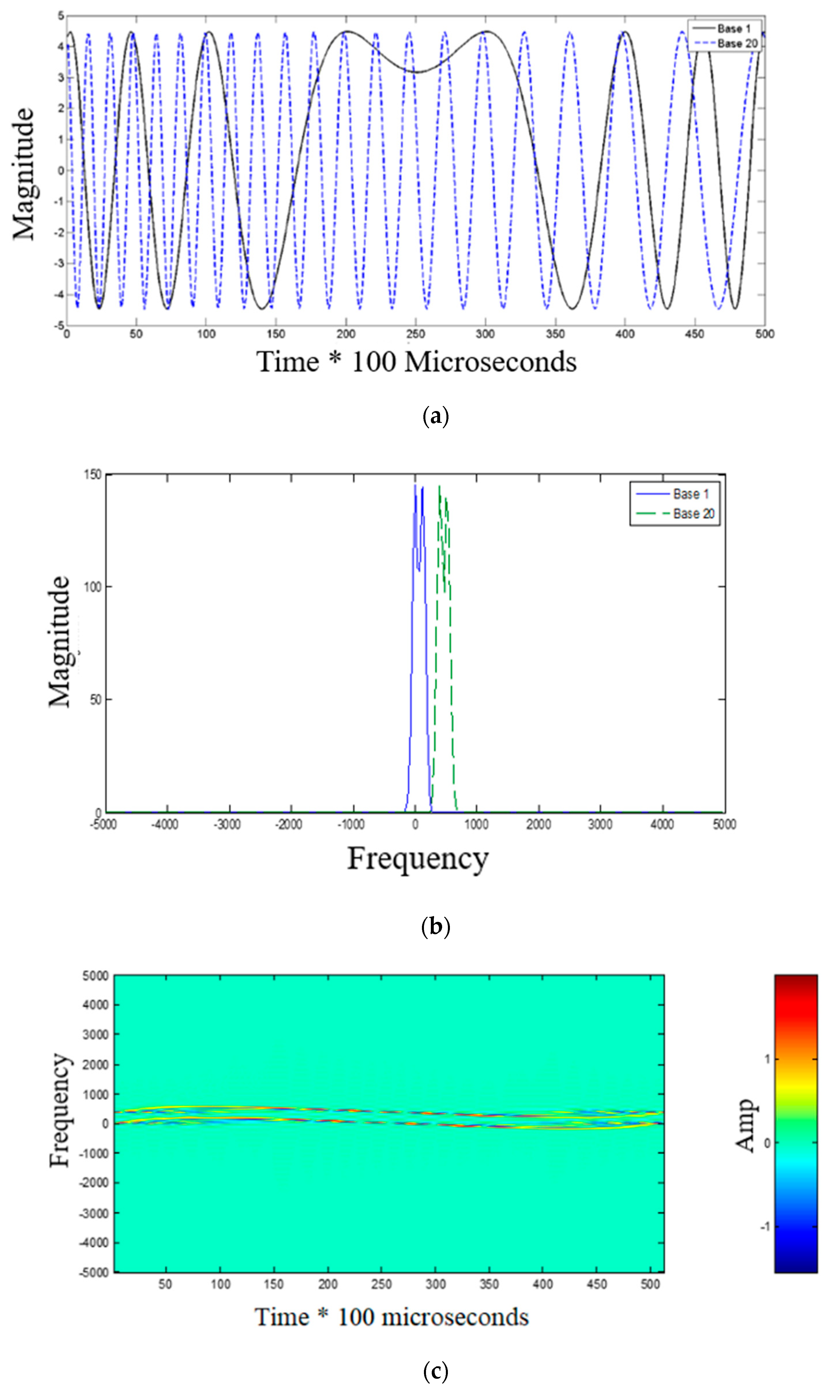
In an OFDM scenario, DFrFT [17] is used to map the in-phase and quadrature (IQ) symbols of QPSK modulation data of different subcarriers to chirp waveforms. Figure 2 displays the chirp waveforms, spectral energy distribution and Wigner distribution of signals from the 1st and 20th subcarrier.
A considerable amount of research has proposed different kinds to discrete FrFT (DFrFT), but many of them do not meet the requirements of all the required properties of continuous FrFT. The choice of DFrFT depends on the real application. In the work proposed in this paper, eigen-decomposition DFrFT [18] is applied due to its property of “orthogonality”, “reversible” and “additivity”, suitable for OFDM communication system. The DFrFT of order α can be written in matrix vector multiplication as [19]
r α = F α s
where the signal in DFrFT domain is r α = [ r α ( 1 ) ,   r α ( 2 ) r α ( N ˜ ) ] , the signal in time domain is s = [ s ( 1 ) ,   s ( 2 ) s ( N ˜ ) ] , and
F α = [ F α ( 1 , 1 ) F α ( 1 , N ˜ ) F α ( N ˜ , 1 ) F α ( N ˜ , N ˜ ) ]
is the N ˜ point DFrFT transformation matrix in which
F α ( t , u ) = n = 0 ϑ n [ t ] e j π 2 n α ϑ n [ u ]   t ,   n [ 1 : N ˜ ]
The DFrFT kernel F α ( t , u ) [19] consists of three parts, similar to the eigen-decomposition of DFT kernel. Both ϑ n [ t ] and ϑ n [ u ] are discrete Hermite-Gaussian functions, while e j π 2 n α is the eigenvalue of DFrFT kernel.
The IDFrFT is written as
s = F α H r α = F α r α
According to [19], the eigen-decomposition type of DFrFT possesses the property of “additivity”, so
F α 1 + α 2 = F α 1 × F α 2
This property is used in the Partial FrFT element of the proposed system.

2.3. MIMO PFrFT-OFDM System

A DFrFT modulated MIMO-OFDM scenario with M transmitters, and N receivers is considered together with a Partial FFT demodulation at the receiver. The total block duration T = T + T g consists of OFDM symbol duration T and guard interval T g . For each transmitter m , QPSK data d k m modulated in each chirp subcarrier in the Fractional Fourier Domain of order α , where K is the total number of subcarriers IDFrFT used to convert d k m into LFM passband waveforms s α m ( t ) in the time domain
s α m ( t ) = 1 T k = 1 K d k m F α ( t , k )   t [ 0 ,   T ]
where F α ( t , k ) is the α order IDFrFT.
After passing through the known time-varying channel, the received signal at the n t h receiver, r α n ( t ) , is expressed as [7]
r α n ( t ) = m = 1 M p = 1 P n , m h p n , m ( t )   s α m ( t τ p n , m ( t ) ) + z n ( t )   t [ 0 , T ]
where z n ( t ) is the additive Gaussian noise and h p n , m ( t ) is the time varying amplitude for the p t h channel of the ( m , n ) t h transmitter-receiver pair.
As shown in Figure 1b the duration of r α n ( t ) , T, is separated into B non-overlapping intervals via non-overlapping rectangular window, followed by each segment of r α n ( t ) demodulated by FFT, contributing to output of b t h interval of i t h subcarrier written as
r i _ α n ( b ) = 1 T ( b 1 ) T B b T B r α n ( t ) e j 2 π f i t d t = 1 T m = 1 M k = 1 K d k m F α + 1 ( t , k ) ( b 1 ) T B b T B H ˜ i , k n , m ( t ) e j 2 π ( k i ) Δ f t d t + z i _ α n ( b ) b = 1 ,   2 , ,   B
in which i [ 1 : K ] is the index of subcarrier in received signal, n [ 1 : N ] is the index of receiver, b [ 1 : B ] is the index of partial segments,
H ˜ i , k n , m ( t ) = p = 1 P n , m h p n , m ( t ) e j 2 π f i ( τ p n , m a p n , m t )
is time varying channel frequency response in Equation (8), and z i _ α n ( b ) denotes additive noise of b t h interval of i t h subcarrier.
Assuming that the UWA channel impulse response changes slowly over each segment, then the time variant channel frequency response over each partial FFT interval [ ( b 1 ) T B , b T B ] can be represented by its midpoint value, r i _ α n ( b ) which can be written as
r i _ α n ( b ) = m = 1 M k = 1 K d k m F α + 1 H ˜ i , k n , m ( b ) v k i ( b ) + z i _ α n ( b )
where
v k i ( b ) = 1 T ( b 1 ) T B b T B e j 2 π ( k i ) Δ f t d t = 1 B e j π ( k i ) ( 2 b 1 ) B s i n c ( π ( k i ) B ) k i = K + 1 , ,   K 1
Equation (10) can be written in matrix -vector form, as
r i _ α n = m = 1 M k = 1 K d k m F α + 1 H ˜ i , k n , m v k i + z i _ α n
where r i _ α n = [ r i _ α n ( 1 ) , r i _ α n ( 2 ) r i _ α n ( B ) ] T , v k i = [ v k i ( 1 ) , v k i ( 2 ) v k i ( B ) ] T , z i _ α n = [ z i _ α n ( 1 ) , z i _ α n ( 2 ) z i _ α n ( B ) ] T and H ˜ i , k n , m = d i a g { [ H ˜ i , k n , m ( 1 ) , H ˜ i , k n , m ( 2 ) H ˜ i , k n , m ( B ) } .
The output of all K symbol subcarriers for at b t h interval of n t h receiver can be written as
[ r 1 _ α n ( b ) r K _ α n ( b ) ] = [ H n , 1 ( b ) H n , M ( b ) ] [ d 1 d M ] + [ z 1 _ α n ( b ) z K _ α n ( b ) ]
where d m = [ d 1 m   d 2 m d K m ] T contains symbol of all the K subcarriers at m t h receiver; and H n , m ( b ) is the channel frequency coupling matrix for all K symbol subcarriers at b t h interval of ( m , n ) t h transmitter-receiver pair which can be written as
H n , m ( b ) = [ H ˜ 1 , 1 n , m ( b ) v 1 1 ( b ) H ˜ 1 , K n , m ( b ) v K 1 ( b ) H ˜ K , 1 n , m ( b ) v 1 K ( b ) H ˜ K , K n , m ( b ) v K K ( b ) ]
The majority of symbol energy for all K subcarriers is concentrated along diagonal of H n , m ( b ) , while the ICI caused by time variant UWA channel which are distributed across neighboring subcarriers, remain to be mitigated using a successive weight combining process w i _ α n = [ w i _ α n ( 1 ) , w i _ α n ( 2 ) w i _ α n ( B ) ] . The vector of output at i t h subcarrier for n t h receiver after weight combining is obtained by
d ^ i n = w i _ α n r i _ α n
What we need to do next is to compute w i _ α n .
As ICI at one subcarrier is mainly caused by subcarriers within its near neighborhood, a parameter D the “ICI span”, is defined which means that each symbol only affects it D direct neighbours on each side, as illustrated in Figure 3.
Re-writing Equation (13) as follows:
[ r 1 α n ( b ) r K α n ( b ) ] = [ H d n , 1 ( b ) H d n , M ( b ) ] [ d 1 d M ] + [ H n , 1 ( b ) H d n , 1 ( b ) H n , M ( b ) H d n , M ( b ) ] [ d 1 d M ] + [ z 1 α n ( b ) z K α n ( b ) ] = [ H d n , 1 ( b ) H d n , M ( b ) ] [ d 1 d M ] + H r n
where
H d n , m ( b ) = { [ H n , m ( b ) ] i , i + d K + 1 D d D 0 o t h e r w i s e
contains main diagonals and two D off-diagonals (super and sub) extracted from H n , m ( b ) , while H r n is the interference, including the ICI beyond the “ICI span” and additive noise.
Then, the output vectors related to i t h subcarrier r i _ α n ( b ) are extracted from equation (16), leading to
r ˜ i _ α n ( b ) = [ H ˜ d n , 1 ( b ) H ˜ d n , M ( b ) ] H ˜ d n ( b )   [ d ˜ i 1 d ˜ i M ]
where r ˜ i _ α n ( b ) = [ r i D _ α n ( b ) r i _ α n ( b ) r i + D _ α n ( b ) ] T is a ( 2 D + 1 ) size vector including not only output of i t h subcarrier, but also its neighboring subcarriers for successive weight computation. d ˜ i m = [ d k 2 D m d k m d k + 2 D m ] T is a ( 4 D + 1 ) size input vector. H ˜ d n , m ( b ) is a square matrix with size of ( 2 D + 1 ) × ( 4 D + 1 ) extracted from H d n , m ( b ) related to r ˜ i _ α n ( b ) , shown below:
H ˜ d n , m ( b ) = [ H i D , i 2 D n , m ( b ) H i D , i n , m ( b ) H i + D , i n , m ( b ) H i + D , i + 2 D n , m ( b ) ]
H ˜ d n ( b ) in equation (18) can be written as
H ˜ d n ( b ) = H ˜ d n ( b ) + h ˜ i n , m ( b )
where h ˜ i n , m ( b ) = [ H i D , i n , m ( b ) H i + D , i n , m ( b ) ] T denotes i t h column of H ˜ d n ( b ) , H ˜ d n ( b ) is obtained by H ˜ d n ( b ) discarding h ˜ i n , m ( b ) .
The weight combining for the i t h subcarrier at b t h interval is given by
w i _ α n ( b ) = h ˜ i n , m ( b ) H ( H ˜ d n ( b ) H ˜ d n ( b ) H + N ˜ 0 B + h ˜ i n , m ( b ) h ˜ i n , m ( b ) H ) 1
where N ˜ 0 = d i a g ( N ˜ 0 1 I 2 D + 1 , N ˜ 0 2 I 2 D + 1 N ˜ 0 N I 2 D + 1 ) .
As D becomes larger, the matrix inversion of ( H ˜ d n ( b ) H ˜ d n ( b ) H + N ˜ 0 Q + h ˜ i n , m ( b ) h ˜ i n , m ( b ) H ) 1 leads to ill-conditioned matrix and a significant increase in computational complexity over a single tap weight combining. In order to solve the problem of matrix inversion in MMSE criterion an LDL H factorization is implemented
LDL H = ( H ˜ d n ( b ) H ˜ d n ( b ) H + N ˜ 0 Q + h ˜ i n , m ( b ) h ˜ i n , m ( b ) H ) 1
Instead of calculating the inverse in (21), (22), the following equations are used:
( LDL H ) 1 r ˜ i _ α n ( b ) = β i _ α n
r ˜ i _ α n ( b ) = L D L H β i _ α n β 1 ,   i _ α n β 2 ,   i _ α n
Equation (23) is solved by forward substitution to obtain β 2 ,   i _ α n via the lower left triangular matrix L and a rescaling by the diagonal matrix D 1 to calculate β 1 ,   i _ α n . Finally, back substation with the upper right triangular L H yields β i _ α n , which can be inserted into (20) in order to determine d ^ i _ α n .
After the computation of d ^ i _ α n , the data detected is converted from frequency domain back to fractional domain via ( α 1 )-order DFrFT, as follows
d ^ i n = F α 1 d ^ i _ α n

2.4. Selection of Optimal Fractional Order

As indicated in Equations (13)–(18), the majority energy of H n , m ( b ) is spread in “ICI span”, which includes main diagonals and two D off-diagonals extracted from H n , m ( b ) , denoted as H d n , m ( b ) . The allocation of its power changes according to fractional order α of PFrFT-OFDM. When the system reaches its optimal fractional order α opt , the power in H d n , m ( b ) will reach maximum value, which means power beyond “ICI span” contributes to the least interference. Consequently, the search of optimal order α opt is based on exploiting carrier–to-interference ratio (CIR), defined as
CIR = E ( | | H d n , m ( b ) d m | | F 2 ) E ( | | ( H n , m ( b ) H d n , m ( b ) ) d m | | F 2
where | | . | | F 2 denotes the Frobenius Norm.
The optimal order can be estimated as a maximum CIR problem, as follows
α opt = arg { max α [ 0 , 2 ] [ CIR ] }
The coarse to precise iterative search approach [20] can be applied within the range of α from −1 to1. It is obvious that the selection of optimal order α depends on the UWA channel properties, including number of subcarriers K, Doppler distortion, number of resolvable paths, and channel power delay profile.

2.5. Complexity Consideration

The computational cost analysis of whole system of both PFrFT- LDL H and G-PFFT [1] are provided in Table 1.
The complexity of PFrFT- LDL H consists of three parts, including (i) calculation of LDL H based weight combining algorithms O(B(8D2 + 22D + 4)K), (ii) computation of PFFT and ( α 1 )-order DFrFT O ( K 2 ) , and (iii) B times of FFT demodulation O ( B K l o g K ) . As seen, there are three key parameters affecting the complexity, including the subcarrier number K, ICI span D and partial interval number B. As seen in Table 1 the complexity of the whole G-PFFT system consists of (i) calculation of weight combining algorithm O ( K B 3 ) + O ( K 2 B 2 ) and (ii) computation of B times of FFT demodulation O ( B K l o g K ) . It can be seen that the PFrFT- LDL H outperforms G-PFFT with a decrease in complexity. According to the weight combining part of the whole system, a comparative computational cost analysis per iteration between LDL H , BMMSE and the weight combining of G-PFFT system is provided in Table 2.
It can be seen that the implementation of LDL H requires O(Q(8D2 + 22D + 4)K) flops per iteration, which is less than the cost of BMMSE and general partial FFT. The complexity of weight combining algorithms of G-PFFT scenario rely on B times computation of one matrix inversion and two covariance matrices, with the cost of O ( K B 3 ) + O ( K 2 B 2 ) altogether.

3. Simulation Result and Discussion

In this section, the performance of the proposed algorithms are evaluated using simulations.

3.1. Parameter of MIMO-OFDM

We design a MIMO-OFDM system with subcarriers of K = 256, in which carrier frequency and baseband frequency is f c = 10 kHz and B w = 12 kHz respectively. The bandwidth of each subcarrier spacing is Δ f = B w K = 46.875 Hz, while the OFDM symbol duration is T = 1 Δ f = 21.33 ms.
A cyclic prefix interval T g = T 8 = 2.67 ms is inserted to eliminate inter-symbol interference (ISI).

3.2. Parameter of UWA Channel

The channels of MIMO system are assumed independent. The multipath delay for each path is distributed exponentially duration of maximum delay spread approximately τ m a x = 2.5 ms. The average power reduces exponentially with delay, while the amplitudes are Rayleigh distributed. The normalized Doppler spread f d T = 0.1 ,   0.2 ,   0.3   a n d   0.4 respectively. The signal to noise ratio (SNR) per channel ranges from to 0 to 30 dB.

3.3. Simulation Analysis

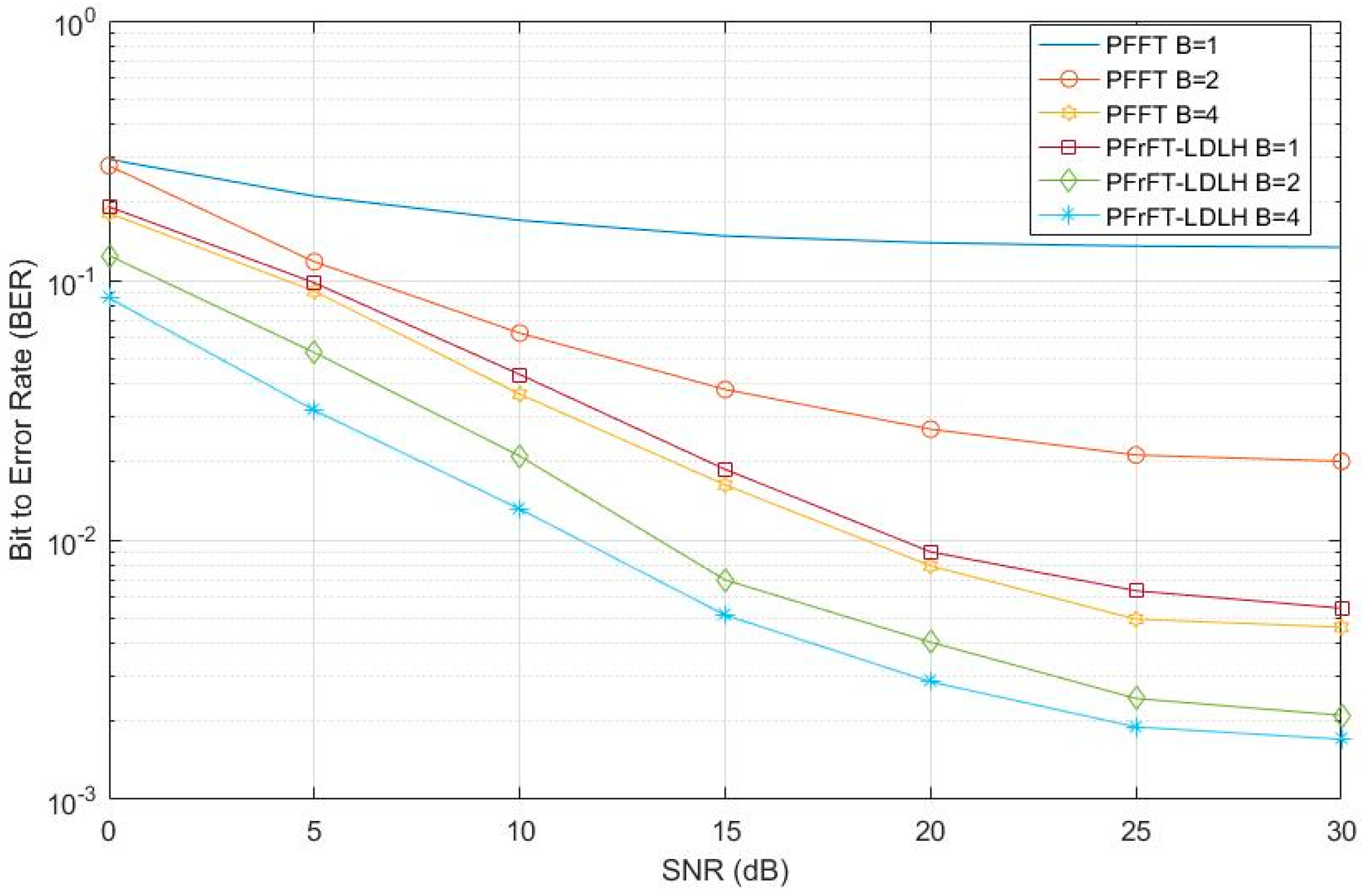
Figure 4 shows the relative perfomance characteristics between the PFrFT-LDLH and the PFFT for B = 1, 2 and 4 and 10,000 Monte Carlo runs.
It is assumed that the time-variant channel information is perfect with f d T = 0.4 and number of partial segments are selected as B = 1, 2, and 4, respectively. The DFrFT optimal order is α is searched in range of [0, 2] by fine-to-coarse method [20] and α = 0.7, The ICI span for channel frequency matrix and LDL H equalization is D = 3. It is seen that the performance of PFrFT- LDL H is superior to that of the PFFT with a BER improvement of 13 dB for B = 1, 9 dB for B = 2, and 3 dB for B = 4. The reasons for positive results are attributed to increase of ICI span and better energy aggregation along the diagonal of channel frequency coupling matrix for DFrFT than that of conventional DFT.
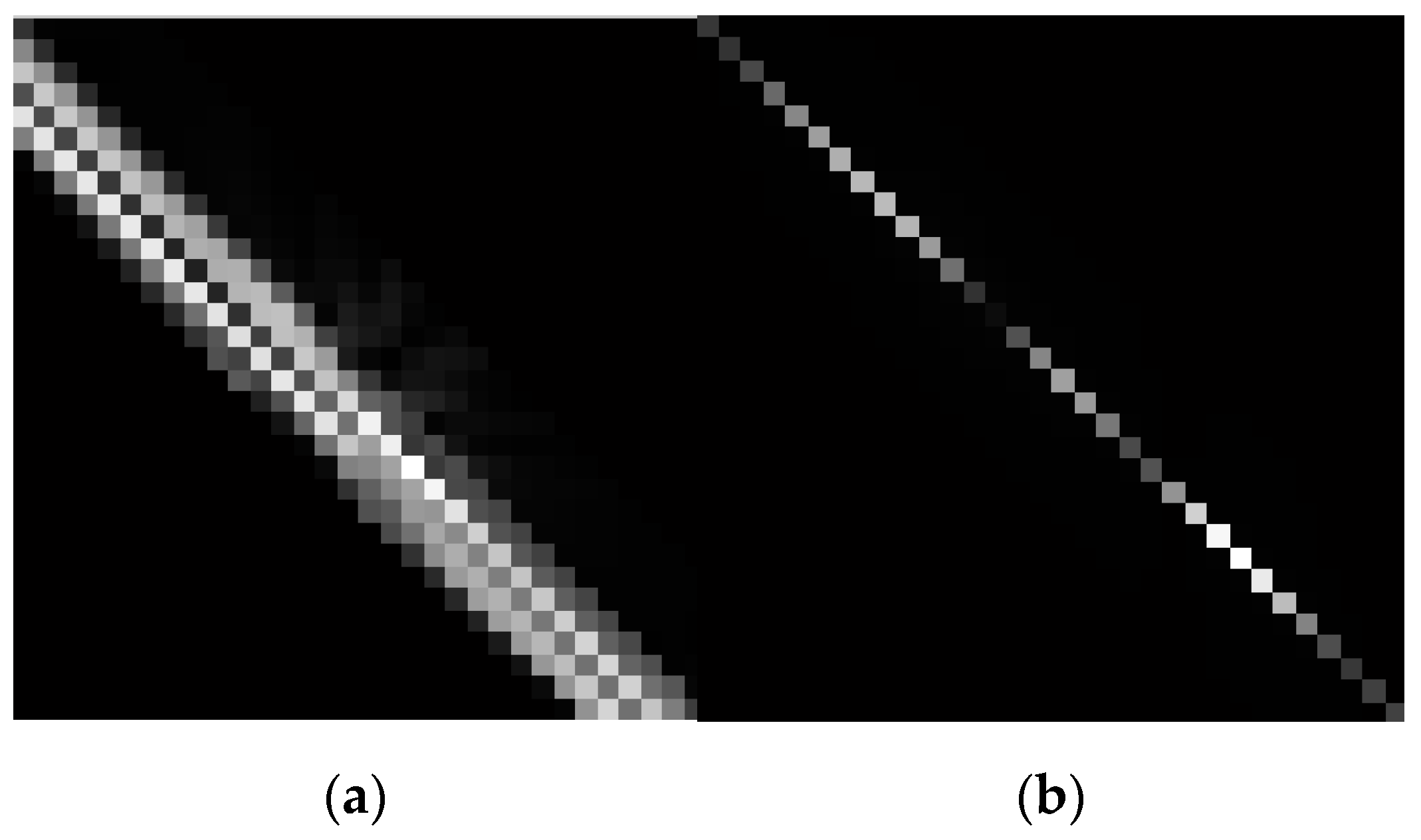
The channel frequency matrices for both PFFT and PFrFT are shown in Figure 5a,b respectively. In Figure 5 the channel frequency matrix H df is scalar into a grey level image, the value of which is in the range of [0, 255]. The value “0” means black and “255” means white. The bands, which are diagonal lines in both images with white color represent the energy of H df . The larger the energy, the closer the pixel value will be to “255”. It is can be appreciated that the distribution of the band of PFFT distributes over more frequencies is than that of PFrFT, which means the energy of H df based on PFrFT concentrate closer to the diagonal, leading to less ICI and better BER performance.
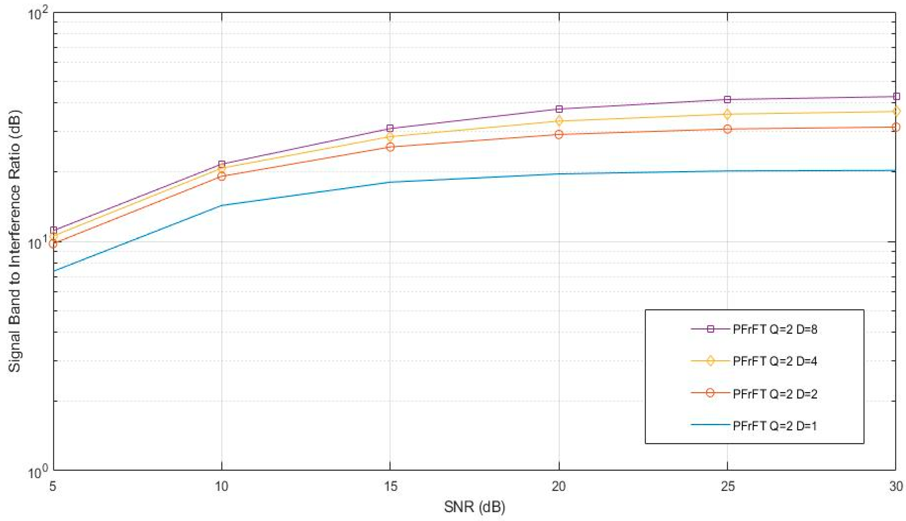
Figure 6 displays how the signal band to interference ratio (SBIR) changes with increase of ICI span D for partial segments B = 2. As D increases, the SBIR improves, but the rate of increase decreases as SNR increases. The reason is that symbol energy congregates among desired signal subcarriers, while the leakage energy of ICI spread into subcarriers alongside. As the index of ICI relative subcarriers increases, the normalized ICI power decrease. As ICI span D increases, more ICI in its neighboring subcarriers are considered for further LDL H equalization, contributing to decrease of residual energy out of ICI span, and finally increases BER performance.
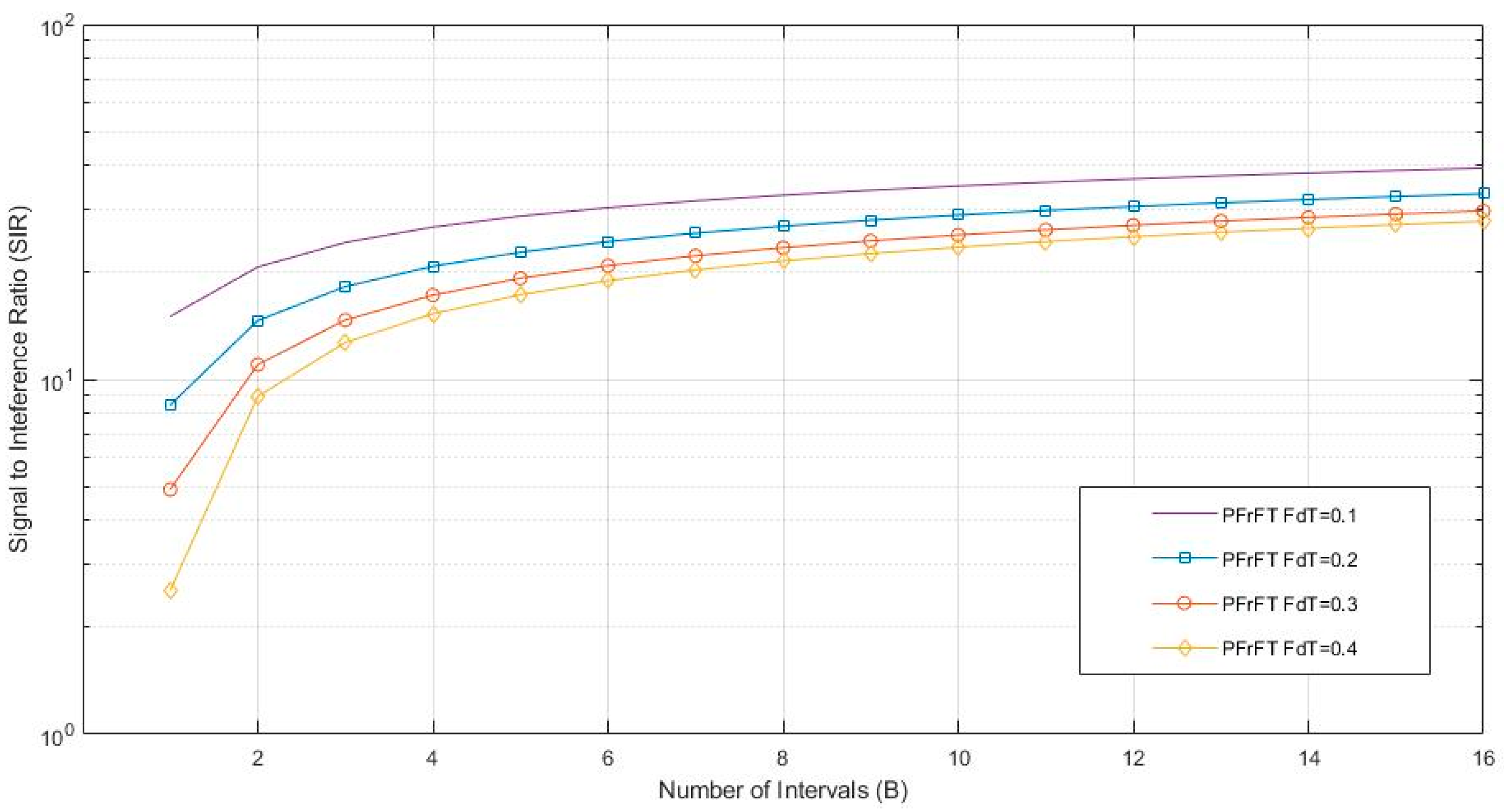
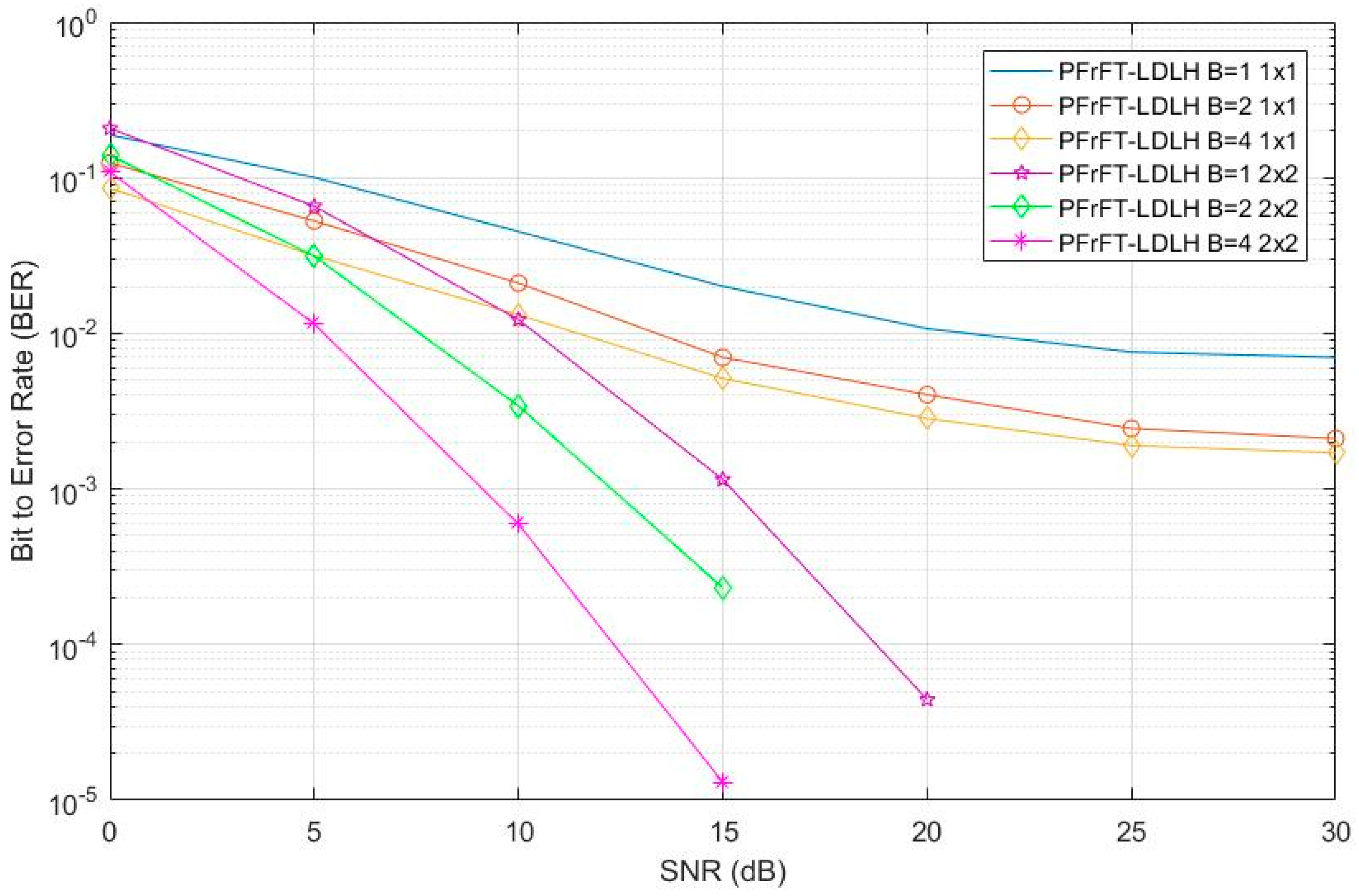
Comparing the performance of PFrFT- LDL H in Figure 4 with B of 1,2, and 4, also confirms that an improved BER is achievable using larger values of B. Figure 7 displays the SIR of PFrFT in PFrFT with B from 0 to 16. The system suffers from the Doppler distortion from F d T = 0.1 to 0.4 and SNR is set at 30 dB. SIR grows with an increase of B, as the growth rate becomes slower. It is obvious that partial segments play a significant role in mitigating residual ICI out of span.
Figure 8 depicts the BER performance of the proposed PFrFT- LDL H algorithm for 2 × 2 MIMO systems with partial segments B = 1, 2, and 4. Time-variant channel information is assumed as perfect with f d T = 0.4 and optimal order is set at 0.86.
It can be seen that an improved BER is achieved in MIMO-OFDM compared to that in the SISO-OFDM due to diversity gains with cost of increase of computational complexity.
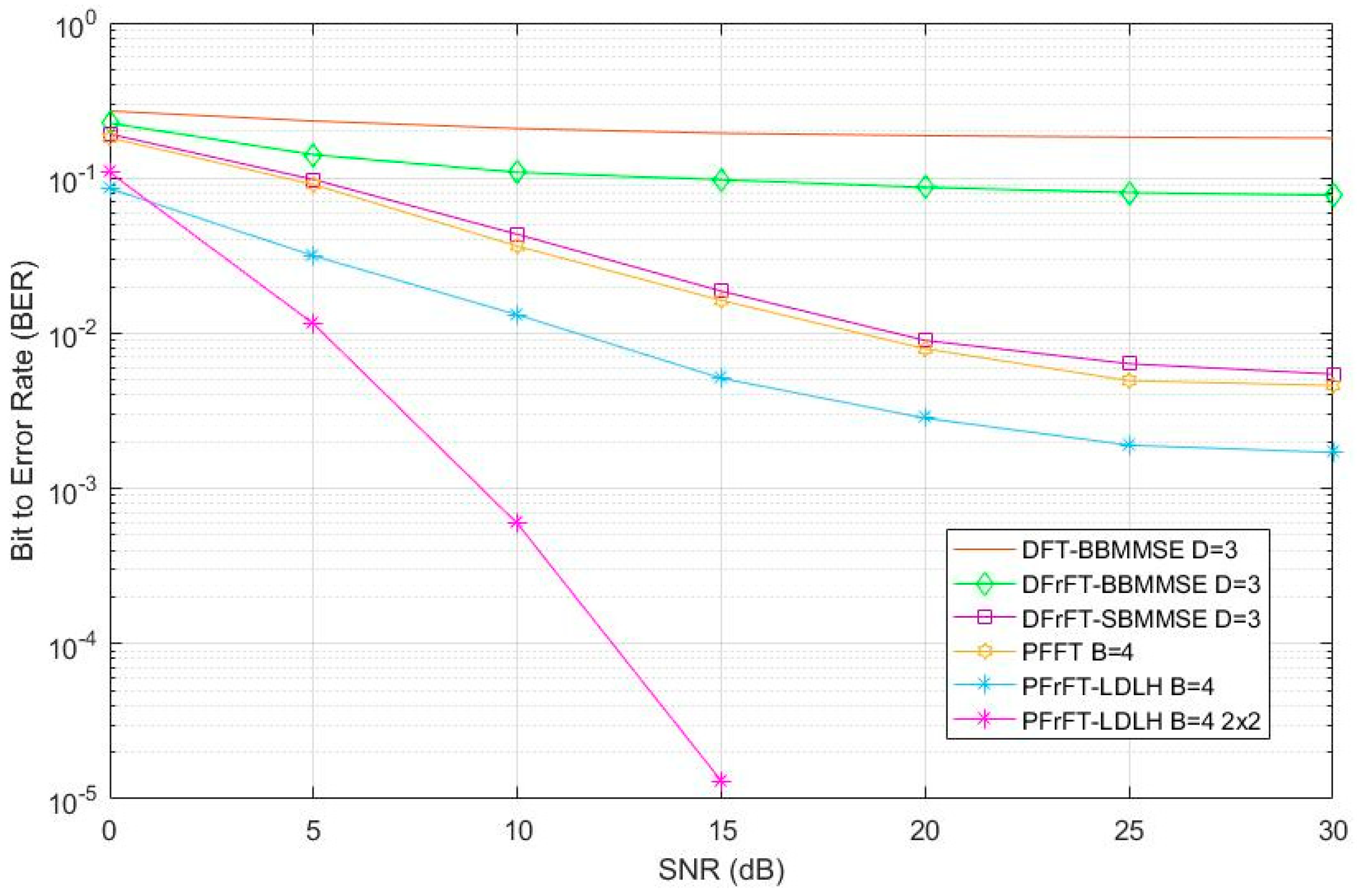
Figure 9 compares the proposed algorithm with other existing approaches. The DFrFT based serial Band MMSE equalization (D = 3) and conventional Partial FFT (B = 4) achieves a moderate performance and their performance are close to each other. The proposed PFrFT- LDL H outperforms the other methods in SISO OFDM scenario and its performance can be improved in MIMO OFDM scenario. At SNR = 15 dB the performance of the B = 4 for MIMO system with N × M = 2 × 2 is 25 dB better than B = 4 and 35 dB better than PFFT B = 4 and DFRFT SBMMSE D = 3.

4. Conclusions

In this paper, a novel concept of PFrFT-MIMO-OFDM based on the hybrid use of the discrete fractional Fourier transform (DFrFT), partial Fourier transform (PFFT) demodulation, and low complexity banded MMSE equalization has been proposed. The LDL H based equalizer was applied not only to improve the performance, but also to reduce the computational complexity. The ICI is significantly mitigated under doubly selective UWA channel compared to the DFrFT-OFDM, PFFT-OFDM at moderate complexity providing an improvement in the overall Bit Error Rate.

Author Contributions

Writing—original draft, Y.C.; writing—review and editing, C.C. and J.J.S. All authors have read and agreed to the published version of the manuscript.

Funding

This research received no external funding.

Conflicts of Interest

The authors declare no conflict of interest.

References

  1. Yerramalli, S.; Stojanovic, M.; Mitra, U. Partial FFT demodulation: A detection method for highly Doppler distorted OFDM systems. IEEE Trans. Signal Process. 2012, 60, 5906–5918. [Google Scholar] [CrossRef] [Green Version]
  2. Li, B.; Huang, J.; Zhou, S.; Ball, K.; Stojanovic, M.; Freitag, L.; Willett, P. MIMO-OFDM for high-rate underwater acoustic communications. IEEE J. Ocean. Eng. 2009, 34, 634–644. [Google Scholar]
  3. Tao, J. DFT-precoded MIMO OFDM underwater acoustic communications. IEEE J. Ocean. Eng. 2017, 43, 805–819. [Google Scholar] [CrossRef]
  4. Qiao, G.; Babar, Z.; Ma, L.; Liu, S.; Wu, J. MIMO-OFDM underwater acoustic communication systems—A review. Phys. Commun. 2017, 23, 56–64. [Google Scholar] [CrossRef]
  5. Stojanovic, M.; Preisig, J. Underwater acoustic communication channels: Propagation models and statistical characterization. IEEE Commun. Mag. 2009, 47, 84–89. [Google Scholar] [CrossRef]
  6. Li, B.; Stojanovic, S.Z.M.; Freitag, L.; Willet, P. Multicarrier Communication over underwater acoustic channels with nonuniform Doppler shifts. IEEE J. Ocean. Eng. 2008, 33, 198–209. [Google Scholar]
  7. Schniter, P. Low-complexity equalization of OFDM in doubly selective channels. IEEE Trans. Signal Process. 2004, 52, 1002–1011. [Google Scholar] [CrossRef]
  8. Huang, J.; Zhou, S.; Huang, J.; Berger, C.R.; Willett, P. Progressive inter-carrier interference equalization for OFDM transmission over time-varying underwater acoustic channels. IEEE J. Sel. Top. Signal Process. 2011, 5, 1524–1536. [Google Scholar] [CrossRef]
  9. Fang, K.; Rugini, L.; Leus, G. Low-complexity block turbo equalization for OFDM systems in time-varying channels. IEEE Trans. Signal Process. 2008, 56, 5555–5566. [Google Scholar] [CrossRef] [Green Version]
  10. Rugini, L.; Banelli, P.; Leus, G. Low-complexity banded equalizers for OFDM systems in Doppler spread channels. EURASIP J. Appl. Signal Process. 2006, 2006, 1–13. [Google Scholar] [CrossRef] [Green Version]
  11. Li, Y.; Sha, X.; Zheng, F.; Wang, K. Low Complexity Equalization of HCM Systems with DPFFT Demodulation over Doubly-Selective Channels. IEEE Signal Process. Lett. 2014, 21, 862–865. [Google Scholar]
  12. Aval, Y.M.; Stojanovic, M. Differentially coherent multischannel detection of acoustic OFDM signals. IEEE J. Ocean. Eng. 2014, 40, 251–268. [Google Scholar] [CrossRef]
  13. Chen, Y. Partial Fractional Fourier Transform (PFrFT)-OFDM for underwater acoustic communication. In Proceedings of the European Signal Processing Conference (EUSIPCO), Nice, France, 31 August–4 September 2015. [Google Scholar]
  14. Solyman, A.; Weiss, S.; Soraghan, J.J. Hybrid DFrFT and FFT based Multimode Transmission OFDM System. In Proceedings of the ICEENG, Cairo, Egypt, 29–31 May 2012. [Google Scholar]
  15. Chen, Y. Fractional Cosine Transform (FrCT)-Turbo based OFDM for underwater acoustic communication. In Proceedings of the Sensor Signal Processing for Defence (SSPD), Edinburgh, UK, 9–10 September 2015. [Google Scholar]
  16. Chen, S.; Yang, Y. Low-Complexity MMSE-SIC Equalizer Employing LDLH Factorization for OFDM Systems over Time-Varying Channels. IEEE Trans. Veh. Technol. 2010, 59, 4128–4131. [Google Scholar]
  17. Candan, C.; Kutay, M.; Ozaktas, H. The discrete fractional Fourier transform. IEEE Trans. Signal Process. 2000, 48, 1329–1337. [Google Scholar]
  18. Namias, V. The Fractional Order Fourier Transform and its Application to Quantum Mechanics. IMA J. Appl. Math. 1980, 25, 241–265. [Google Scholar]
  19. Singh, A.K.; Saxena, R. DFRFT: A classified review of recent methods with its application. J. Eng. 2013, 2013, 214650. [Google Scholar]
  20. Zhao, Y.; Yu, H.; Wei, G.; Ji, F.; Chen, F. Parameter estimation of wideband underwater acoustic multipath channels based on fractional Fourier transform. IEEE Trans. Signal Process. 2016, 64, 5396–5408. [Google Scholar]
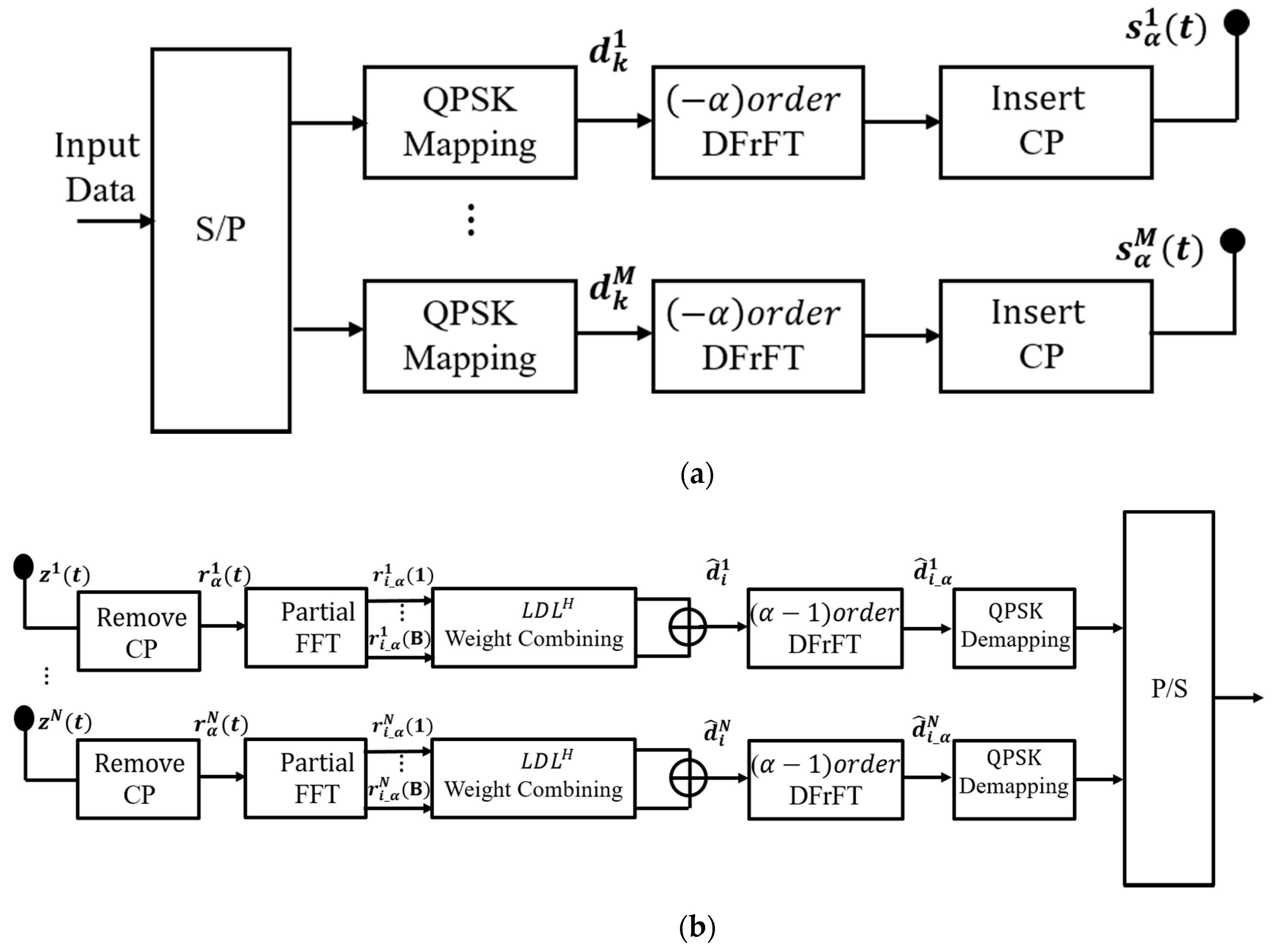
Figure 1. (a) Diagram of transmitter of PFrFT-OFDM with LDL H iterative weight combining in MIMO scenario; (b) diagram of receiver of PFrFT-OFDM with LDL H iterative weight combining in MIMO scenario.
Information 12 00469 g001
Figure 2. (a) Chirp waveforms in time domain; (b) spectral energy distribution; (c) Wigner distribution.
Information 12 00469 g002
Figure 3. The desired structure of H ˜ d n , m ( b ) .
Information 12 00469 g003
Figure 4. BER performance of proposed PFrFT- LDL H compared to PFFT in [1] for a SISO-OFDM scenario. The number of Monte Carlo runs is 10,000 for = B = 1, 2 and 4.
Information 12 00469 g004
Figure 5. Channel frequency matrix ( H df ) of PFFT (a) and PFrFT (b).
Information 12 00469 g005
Figure 6. PFrFT- LDL H with different ICI span D.
Information 12 00469 g006
Figure 7. SIR of PFrFT with increase of B.
Information 12 00469 g007
Figure 8. BER performance for with SISO-PFrFT and MIMO-PFrFT.
Information 12 00469 g008
Figure 9. BER performance of various algorithms.
Information 12 00469 g009
Table 1. Complexity analysis of whole system.
Whole SystemComputational Complexity
PFrFT-LDLH O ( B K l o g K ) + O ( B ( 8 D 2 + 22 D + 4 ) ) + O ( K 2 )
G-PFFT [1] O ( B K l o g K )
+ O ( K B 3 ) + O ( K 2 B 2 )
Table 2. Complexity analysis of different weight combining algorithms.
Weight CombiningComputational Complexity
LDL H O(B(8D2 + 22D + 4)K)
BMMSE O ( B D 3 K )
G-PFFT [1] O ( K B 3 ) + O ( K 2 B 2 )
Publisher’s Note: MDPI stays neutral with regard to jurisdictional claims in published maps and institutional affiliations.