3. Results
The head-fixed prototype was initially designed for 2D (horizontal and vertical) eye movement tracking in a previous work, for which head movements are forbidden. However, it is obviously not suitable for stimulating eye torsion with head movements, so it is difficult to assess the performance of the proposed method with the present prototype. Moreover, there is no standard that clearly indicates the requirements of eye torsion measurement for medical applications. For these reasons, the authors have decided to firstly validate the principle of the present method and evaluate its robustness in a gaze test. The FPR (False Positive Rate) is measured for this purpose to verify if the system does not give mistaken results in the absence of eye torsion.
Five participants (2 males and 3 females) with very different eye morphologies were enrolled in the test, including 3 European eyes, 1 Asian eye and 1 African eye. They were asked to look at the target displayed on the monitor while keeping their head upright and steady. Only zero eye torsion can be measured in the current test, because head movement is forbidden and there is no visual stimulus that may trigger eye torsion in healthy subjects [
23].
The experimental setup is illustrated in
Figure 11. A monitor is placed at 50 cm in front of participant’s eye, such that the target displayed at zero gaze position is already fixed by the participant when the latter is looking straight forward. The targets are displayed in a predefined order. Only one target is shown at a time and it is displayed for 3 s at each position. The test was performed under controlled lights (i.e., low and constant illumination) and the background of the monitor is set to black color to avoid visual distraction. The proposed eye torsion measurement method was executed on a MacBook Pro with an Intel Core i7 (2.8 GHz, Dual-Core), running Microsoft Windows 8.1 under Boot Camp.
A set of 6174 front images of the right eyes were assessed in total. A visual inspection was performed before the analysis to remove the images with missing or inaccurate pupil segmentation in order to focus on eye torsion detection. No eye torsion was observed during the visual inspection, so all non-zero measurements are considered as mistaken detections. The measured FPR is reported in
Table 1.
The accuracy of the present method in the absence of iris distortion and occlusions was demonstrated using the manually shifted iris patterns, as described in
Section 2.3.2.
A large part of the input eye images (i.e., about 2/3) were taken at eccentric eye positions in the current gaze test, and the morphologies of the participants are very different between each other. The obtained results somehow reflect the performance of the proposed methods of iris segmentation and iris rectification (i.e., correction of the iris distortion), showing a great robustness against occlusion and iris distortion in practical conditions, because a very low mean FPR of eye torsion detection is reported (i.e., 3.3%) and only an FPR less than 1% is reported for more than half of the five participants in the current test.
Therefore, the principle of the proposed method in eye torsion measurement is validated, because it always gave correct measurements on the iris patterns with simulated eye torsions (i.e., manually shifted patterns) and rarely provided mistaken detections in the absence of eye torsion in practical conditions.
The present eye torsion measurement method was executed on a single thread and only takes 13 ms per image on average. The image acquisition is set to 30 FPS in the current system, i.e., the interval time between two consecutive frames is about 33 ms. This frame rate was chosen because it is sufficient for most clinical tests that may require 3D (horizontal, vertical and torsional) eye movement tracking and it is commonly adopted by eye tracking systems that are available on the market for medical applications. The required computing time for pupil detection and gaze estimation is about 12 ms per image in the present system. Therefore, the proposed method of eye torsion measurement can be implemented in an online 3D eye tracking system at 30 FPS on a computer with ordinary settings (i.e., no specific hardware configuration is required).
4. Discussion
A wearable eye tracking system is clearly more adequate for eye torsion recording and measurement in practice as previously discussed. Therefore, it will be the first priority for the authors to implement the proposed method into a wearable eye tracking system, so one will be able to freely evaluate its performance (i.e., precision, robustness and computing time) in real application conditions.
The proposed iris segmentation method is more robust against occlusion and ambiguity than image-based approaches, because the iris boundary is computed according to the gaze direction, and the latter is estimated using the result of pupil segmentation, which is less sensitive to noises due to the smaller pupil size than the iris. Nevertheless, the performance of the proposed method still relies on the quality of 2D (horizontal and vertical) eye movement tracking, so some improvements are expected to improve its robustness and to make it useful for every eye tracking system despite the provided precision in gaze estimation. One of the ideas consists of checking additionally the consistency of the obtained result according to image information. More specially, it involves performing a quick detection of the iris boundary within a small range (e.g., a narrow annulus) around the estimated iris. It will allow the system to detect unreliable estimations of the iris boundary as well as the gaze direction and will not cause important additional processing time.
In order to identify the causes of higher FPR that were reported for the two last participants, the referent iris patterns of all participants were extracted and compared. They are listed in
Table 2 and are sorted in descending order of the measured FPR.
One can see that both iris patterns in question contain a part of the lower eyelid, which seems to be the main source of error. A rectangular mask is currently used to prevent the occlusion of the upper eyelid, which can also be applied on the lower eyelid. However, it is more difficult to determine a fixed mask in this case, because the shape and intruded surface of lower eyelid vary a lot between individuals. Therefore, a new method has to be defined in future developments to accurately remove all intruded eyelids from the iris pattern.
The iris pattern of Participant 5 is more textureless and blurred than the others. A global and unique iris texture is considered in the present work, for which its uniqueness is determined by some distinct textures or characteristic features. The iris pattern of Participant 2 is a great example. Otherwise, the system will not be able to measure the displacement of a flat iris pattern, due to the absence of distinctive markers. Some advanced filters were applied in related works to bring out the iris texture [
4], but their effectivity on such a textureless iris needs to be evaluated. The modification of the hardware will be another choice. The image resolution can be increased to capture more details of the iris, but the processing will be consequently slowed. One can also try to highlight the striations of the iris surface by adding some transverse light sources, while extra reflections will be observed in the captured eye images. All these propositions show some advantages and drawbacks, so an assessment on a larger image set taken from more participants will be needed to make a decision.
The width of the unrolled iris pattern is set to 360 pixels in the present work to offer a precision of 1° in the measurement of torsional eye movement. There is no available standard that clearly determines the clinical requirement of the precision in eye torsion measurement, and it is still unclear how practitioners interpret and use these results in diagnosis. For these reasons, the authors decided to only detect the presence of eye torsion with rough measurements in this work. A collaboration with practitioners is expected in future works to better determine their needs, and the precision of the present method in eye torsion measurement will be further improved according to the determined requirements.
Only five participants were enrolled in the current assessment. It was sufficient to validate the principle of the present method in eye torsion measurement as a preliminary test, whereas it will be important to perform a complete and statistical assessment to evaluate its performance (i.e., precision, robustness and processing time) with a large and significant sample size in future works. The precision can be assessed using artificial eyes or on the simulated eye images, and the robustness can be further evaluated through a clinical assessment. A comparison test with existing systems for eye torsion measurement will be interesting, especially with the gold standard (i.e., scleral search coil) that is already widely used in medical applications for 3D (horizontal, vertical and torsional) eye movement tracking. The proposed method may have to be speeded up to address the requirements of different clinical tests, so its processing time will be independently assessed for this reason.
Author Contributions
Conceptualization, N.J., S.M., J.S. and S.C.; methodology, N.J.; software, N.J.; validation, N.J.; formal analysis, N.J.; investigation, N.J.; resources, N.J.; data curation, N.J.; writing—original draft preparation, N.J.; writing—review and editing, N.J., S.M., J.S. and S.C.; visualization, N.J.; supervision, S.B., J.S. and S.C.; project administration, N.J.; funding acquisition, S.C. All authors have read and agreed to the published version of the manuscript.
Funding
This research was funded by SYNAPSYS.
Conflicts of Interest
The authors declare no conflict of interest.
References
- Gatinel, D. Principaux et axes angles utiles en topographie cornéenne. In Topographie Cornéenne; Elsevier Masson, Ed.; Elsevier: Paris, France, 2011; pp. 19–24. ISBN 9782294711343. [Google Scholar]
- Moore, S.T.; Curthoys, I.S.; McCoy, S.G. VTM—An image-processing system for measuring ocular torsion. Comput. Methods Programs Biomed. 1991, 35, 219–230. [Google Scholar] [CrossRef]
- Lee, I.B.; Park, K.S. Measurement of ocular torsion using iterative Lucas-Kanade optical flow method. In Proceedings of the 2005 IEEE Engineering in Medicine and Biology 27th Annual Conference, Shanghai, China, 17–18 January 2006; pp. 6433–6436. [Google Scholar]
- Otero-Millan, J.; Roberts, D.C.; Lasker, A.; Zee, D.S.; Kheradmand, A. Knowing what the brain is seeing in three dimensions: A novel, noninvasive, sensitive, accurate, and low-noise technique for measuring ocular torsion. J. Vis. 2015, 15, 11. [Google Scholar] [CrossRef] [PubMed]
- Clarke, A.H.; Ditterich, J.; Drüen, K.; Schönfeld, U.; Steineke, C. Using high frame rate CMOS sensors for three-dimensional eye tracking. Behav. Res. Methods Instrum. Comput. 2002, 34, 549–560. [Google Scholar] [CrossRef]
- Nakagomi, H.; Hoshino, K. Measurement of Torsional Eye Movement Using Terminal Points of Conjunctival Blood Vessels. In Proceedings of the MVA2013 IAPR International Conference on Machine Vision Applications, Kyoto, Japan, 20–23 May 2013; pp. 4–7. [Google Scholar]
- Zhu, D.; Moore, S.T.; Raphan, T. Robust pupil center detection using a curvature algorithm. Comput. Methods Programs Biomed. 1999, 59, 145–157. [Google Scholar] [CrossRef]
- Kassner, M.; Patera, W.; Bulling, A. Pupil. In Proceedings of the 2014 ACM International Joint Conference on Pervasive and Ubiquitous Computing Adjunct Publication—UbiComp ’14 Adjunct, Seattle, WA, USA, 13–17 September 2014; ACM Press: New York, NY, USA, 2014; pp. 1151–1160. [Google Scholar]
- Long, X. Eye Movement Tracking for Diagnostic Systems. Ph.D. Thesis, Carnegie Mellon University, Pittsburgh, PA, USA, 2010. [Google Scholar]
- Neog, D.R. Research Proficiency Evaluation Project Report—Robust 3D Gaze Estimation; University of British Columbia: Vancouver, BC, Canada, 2012. [Google Scholar]
- Fu, X.; Zang, Y.; Liu, H. A real-time video-based eye tracking approach for driver attention study. Comput. Inform. 2012, 31, 805–825. [Google Scholar]
- Dongheng, L.; Winfield, D.; Parkhurst, D.J. Starburst: A hybrid algorithm for video-based eye tracking combining feature-based and model-based approaches. In Proceedings of the 2005 IEEE Computer Society Conference on Computer Vision and Pattern Recognition (CVPR’05)—Workshops, San Diego, CA, USA, 21–23 September 2005; p. 79. [Google Scholar]
- Arvacheh, E.M.; Tizhoosh, H.R. IRIS Segmentation: Detecting pupil, limbus and eyelids. In Proceedings of the 2006 International Conference on Image Processing, Atlanta, GA, USA, 8–11 October 2006; pp. 2453–2456. [Google Scholar]
- Ryan, W.J.; Woodard, D.L.; Duchowski, A.T.; Birchfield, S.T. Adapting starburst for elliptical iris segmentation. In Proceedings of the 2008 IEEE Second International Conference on Biometrics: Theory, Applications and Systems, Arlington, VA, USA, 29 September–1 October 2008; pp. 1–7. [Google Scholar]
- Sastry, A.V.G.S.; Durga Sri, B. Enhanced segmentation method for iris recognition. Int. J. Comput. Trends Technol. 2013, 4, 68–71. [Google Scholar]
- Haslwanter, T.; Moore, S.T. A theoretical analysis of three-dimensional eye position measurement using polar cross-correlation. IEEE Trans. Biomed. Eng. 1995, 42, 1053–1061. [Google Scholar] [CrossRef] [PubMed]
- Ong, J.K.Y.; Haslwanter, T. Measuring torsional eye movements by tracking stable iris features. J. Neurosci. Methods 2010, 192, 261–267. [Google Scholar] [CrossRef] [PubMed]
- Bradski, G. The OpenCV library. Dr. Dobb J. Softw. Tools 2000, 25, 120–125. [Google Scholar]
- Haslwanter, T. Mathematics of three-dimensional eye rotations. Vision Res. 1995, 35, 1727–1739. [Google Scholar] [CrossRef]
- Donders, F. On the Anomalies of Accommodation and Refraction of the Eye; Moore, W.D., Ed.; New Sydenham Society: London, UK, 1864; ISBN 074531807X. [Google Scholar]
- Tweed, D. Optimizing gaze control in three dimensions. Science 1998, 281, 1363–1365. [Google Scholar] [CrossRef] [PubMed]
- Template Matching—OpenCV 2.4.13.7 Documentation. Available online: https://docs.opencv.org/2.4/doc/tutorials/imgproc/histograms/template_matching/template_matching.html (accessed on 28 February 2020).
- Van Rijn, L.J.; Van Der Steen, J.; Collewijn, H. Instability of ocular torsion during fixation: Cyclovergence is more stable than cycloversion. Vis. Res. 1994, 34, 1077–1087. [Google Scholar] [CrossRef]
Figure 1.
(a) Main steps of the proposed method of eye torsion measurement; (b) the initial iris is transformed according to the gaze direction to estimate current iris; (c) the TM algorithm is applied to measure the shift of current unrolled iris pattern in respect to the referent one.
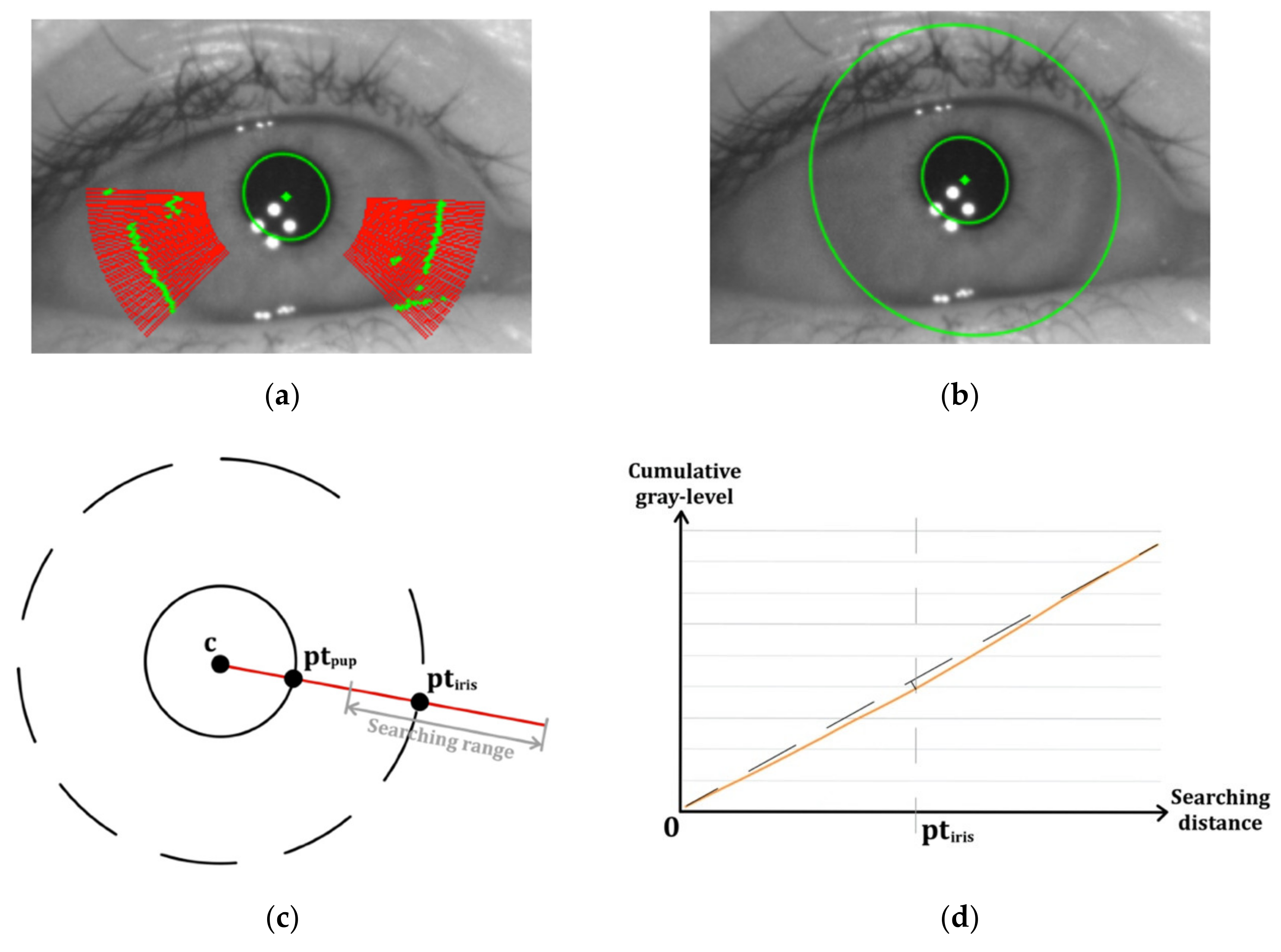
Figure 2.
(a) The pupil (green ellipse) is firstly detected at referent eye position. Several searching rays (red) are projected in radial directions to detect candidate iris boundary points (green); (b) result of initial iris detection at referent eye position; (c) illustration of the searching of the iris boundary along a projected ray. The center of the pupil and the boundary points of the pupil and iris are denoted by, and , respectively. The searching range is indicated in gray; (d) an example of the obtained cumulative gray-level curve (orange), calculated within the searching range along a projected ray. The straight line (dotted line) connecting the two end points of the curve is used to locate the candidate iris point .
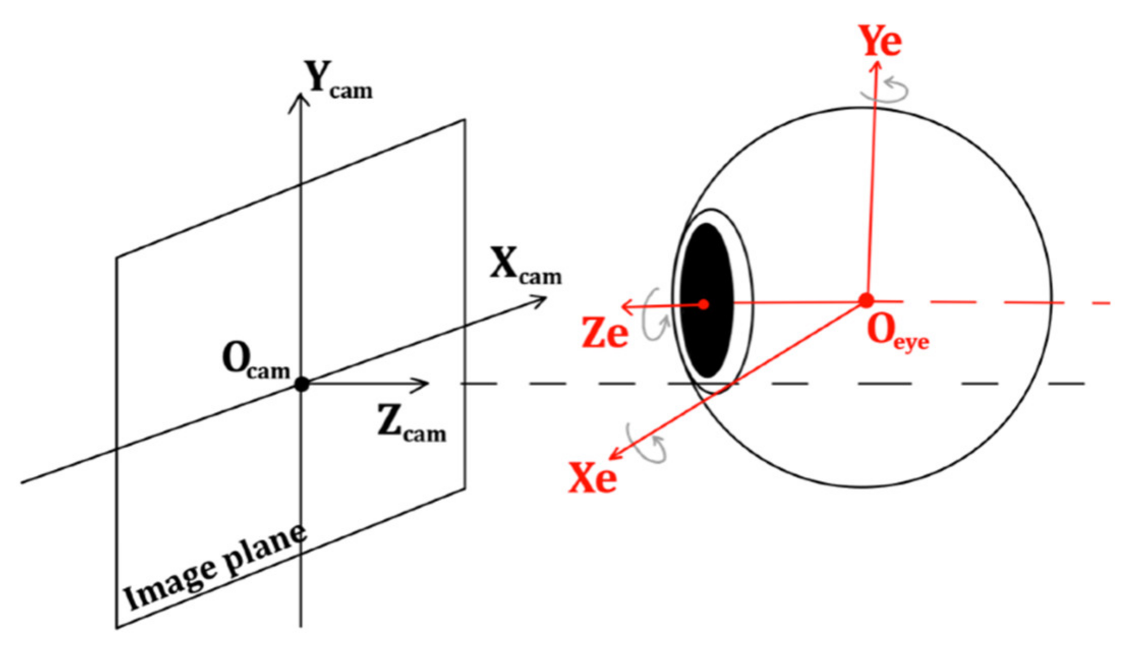
Figure 3.
Illustration of current camera setup, i.e., the eyeball in relation to the camera coordinate frame . An eye coordinate frame is determined at the center of the spherical eyeball.
Figure 4.
(a) Top view of the eye coordinate frame at referent position. The iris plane and the image plane are assumed to be parallel. The initial iris is detected in the eye image and it is centered at ; (b) the iris plane is rotated by . The initial iris is projected from the rotated iris plane onto the image plane , giving .
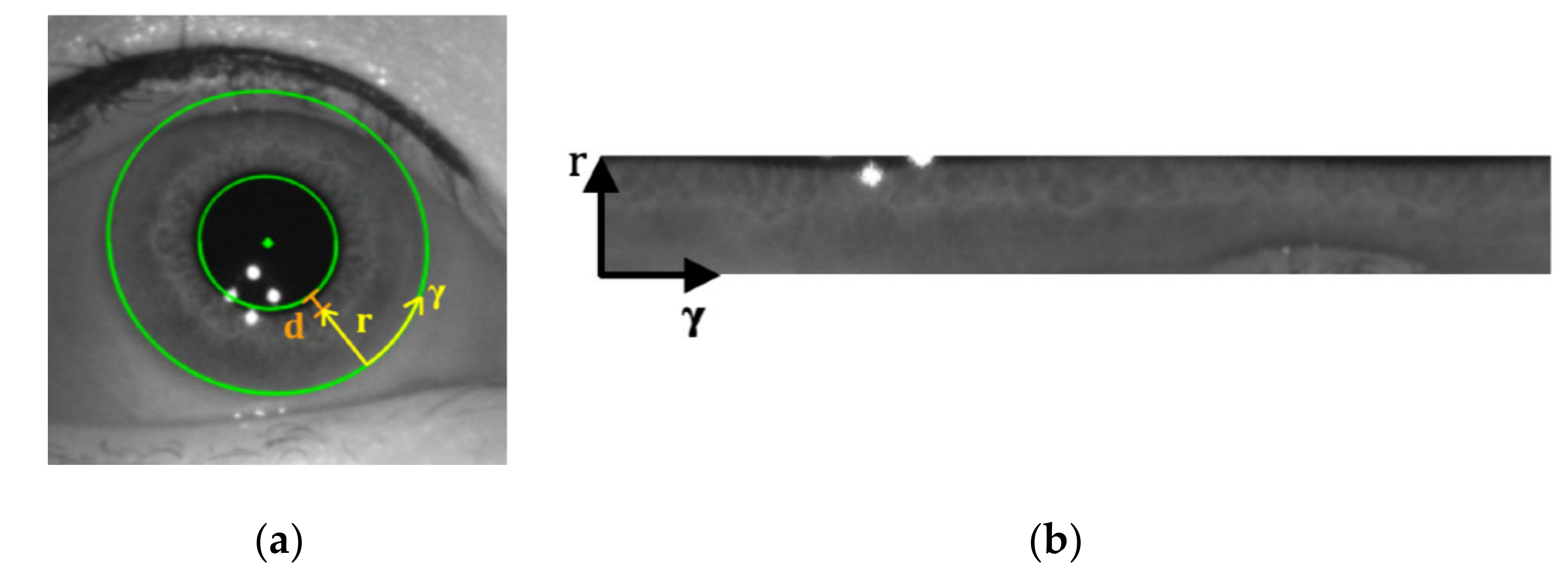
Figure 5.
(a) The iris is unrolled along the mapping axes and ; (b) the iris pattern unrolled from (a).
Figure 6.
(a) Eye image taken at 25° horizontal eye position, with the detected iris to be unrolled; (b) the iris pattern directly unrolled from the current iris; (c) the iris pattern unrolled from current iris using the mapping relation. The black pixels represent the masked areas, including the upper eyelid, eyelashes and CRs.
Figure 7.
(a) Rectangular mask used in present work; (b) a fan-shaped mask.
Figure 8.
(a) The central part of CRs are detected via thresholding; (b) the border of the detected bright spots is then extended in 8 radial directions; (c) result of CR exclusion.
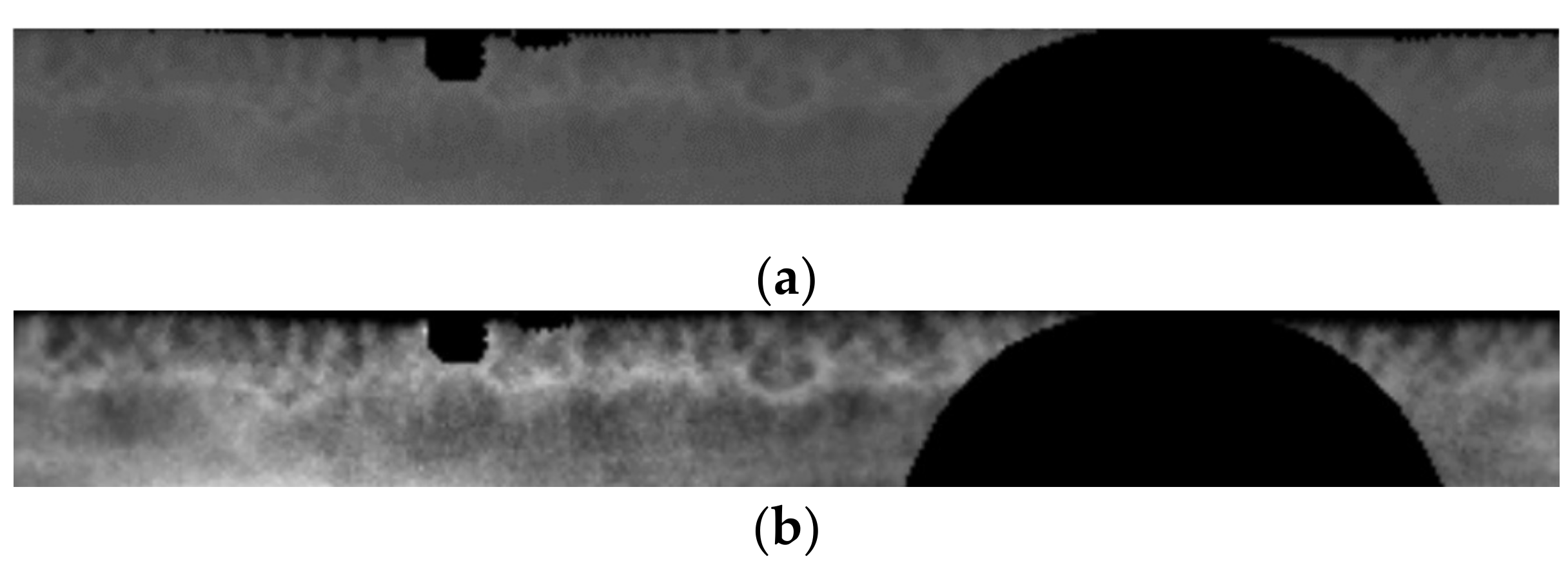
Figure 9.
Unrolled iris pattern: (a) before contrast enhancement; (b) after contrast enhancement.
Figure 10.
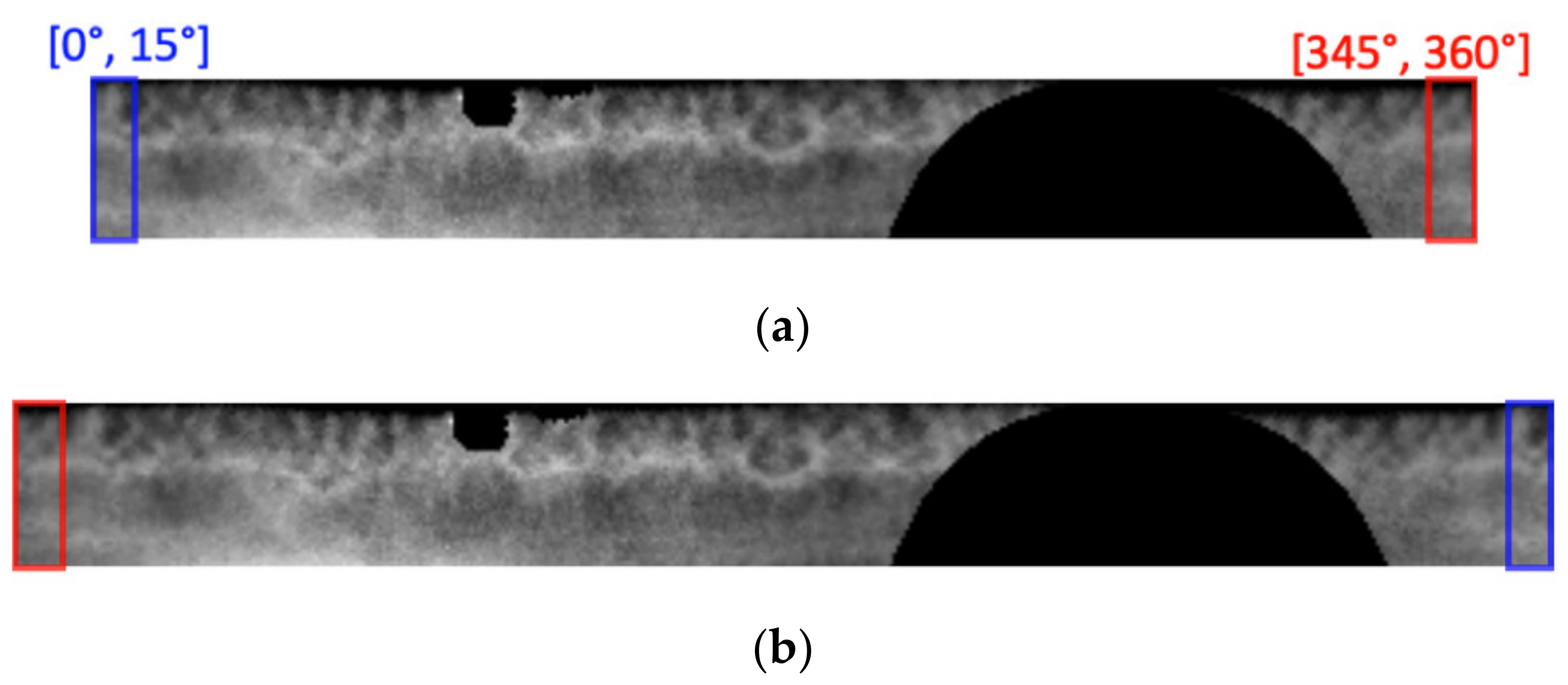
(a) Unrolled referent iris pattern; (b) extended referent iris pattern with redundant pixels at two ends.
Figure 11.
(a) Illustration of the experimental setup; (b) displayed targets (white squares) on the monitor. The grid is not visible during the test and only one target is shown at a time.
Table 1.
Measured FPR of eye torsion detection.
| Participant ID | Number of Images with Mistaken Detection | Number of Input Images | FPR |
|---|
| Participant 1 | 8 | 1208 | 0.7% |
| Participant 2 | 9 | 1258 | 0.7% |
| Participant 3 | 0 | 1258 | 0.0% |
| Participant 4 | 77 | 1193 | 6.5% |
| Participant 5 | 112 | 1257 | 8.9% |
| Overall | 206 | 6174 | 3.3% |
© 2020 by the authors. Licensee MDPI, Basel, Switzerland. This article is an open access article distributed under the terms and conditions of the Creative Commons Attribution (CC BY) license (http://creativecommons.org/licenses/by/4.0/).


