Article

Dew Computing and Asymmetric Security Framework for Big Data File Sharing

School of Information and Software Engineering, University of Electronic Science and Technology of China, Chengdu 610054, China
*
Author to whom correspondence should be addressed.
Information 2020, 11(6), 303; https://doi.org/10.3390/info11060303
Submission received: 17 April 2020 / Revised: 23 May 2020 / Accepted: 28 May 2020 / Published: 5 June 2020

Abstract

:
Due to the advancement of technology, devices generate huge working files at a rapid rate. These data, which are of considerable scale and are created very fast, can be called big data. Keeping such files in one storage device is impossible. Therefore, a large file size is recommended for storage in a cloud storage service. Although this concept is a solution to solve the storage problem, it still faces challenges in terms of reliability and security. The main issues are the unreliability of single cloud storage when its service is down, and the risk of insider attack from the storage service. Therefore, this paper proposes a file sharing scheme that increases both the reliability of the file fragments using a multi-cloud storage system and decreases the risk from insider attack. The dew computing concept is used as a contributor to the file-sharing scheme. The working file is split into fragments. Each fragment is deployed to cloud storage services, one fragment per one cloud provider manner. The dew server controls users’ access and monitors the availability of fragments. Finally, we verify the proposed scheme in aspects of the downloading performance, and security.

1. Introduction

File sharing is an activity where the file owner distributes his or her information to other people or allows verified users to access the current information stored digitally, for example, multimedia files (audio, video, and pictures), computer software, electronic documents, or other electronic formats. In the past, the usual way to store, distribute, and transmit files involved both manual and digital methods. The manual file sharing method was done via removable tangible media such as compact discs (CDs), digital video discs (DVDs), flash drives, or removable hard drives. On the contrary, the digital transfer method is done by computer networks. The file owner stores file in a file server and grants privileged access to authorized users. The authorized user is able to access and downloads the files stored on the file server via the computer network. However, conventional file sharing methods have security and limited storage space issues.
One reasonable solution is cloud storage service renting. Cloud storage service contributes sufficient space and security with affordable service charge. The cloud storage services provide online space where data is stored in non-physical storage hosted by third parties. Usually, the actual data centers cross different geographical areas. Users can access the storage service from anywhere and anytime through their internet-capable devices. The cloud usage concept is pay per use [1,2]. The user does not demand to settle for unused service. Compare using cloud storage with buying a large storage media or server; there is unused storage space remain in the file server, which is an unworthy investment.
Although single cloud storage sounds like a reasonable solution for data sharing, there are single cloud limitation issues [3]. The first limitation is storage capacity. Many cloud storage services grant free storage capacity, which is inadequate for large file usage, and the charge for paid subscriptions that offer higher storage capacity is costly. The second limitation is low performance. The data transfer rate of cloud storage is slower than a local storage device. The available cloud bandwidth is divided among users at the same moment. Consequently, cloud storage providers have to limit bandwidth usage to preserve service quality. The third limitation is vendor lock-in. When users rely on a single cloud provider, it causes a significant risk for users themselves. If the provider abruptly ends its business or service, users may lose their stored data forever. The final limitation is security breaches. Cloud storage providers exclusively manage and maintain the encryption keys by themselves. Consequently, data stored in the providers would be in jeopardy if the provider’s key is endangered. Users are unable to understand providers’ security methods or policies.
In order to overcome single cloud storage limitations, a multi-cloud storage application is an exciting idea [4]. A multi-cloud aggregates various cloud services to form a single application or system. In this case, the multi-cloud storage aggregates multiple storage services from various cloud providers to act as a single storage service. Users can access this system via a developed software interface rather than the default interface or channel provided by cloud storage providers. The main advantages of multi-cloud storage usage are more performance and higher security than single-cloud storage. Users can connect to multi-cloud services at the same time in order to gain more bandwidth. A single-cloud connection is limited and shared due to the bandwidth management policy of a cloud provider itself. Cloud provider has to control bandwidth usage in order to preserve the quality of service.
For security purposes, saving a sensitive file on single-cloud storage puts the file in jeopardy. File owners may lose his or her file for any reason, which causes the cloud storage to go offline or out of service, for example, disasters, internal, or external electronic attacks. On the contrary, the file owner slices the file into fragments and deploy them to multiple clouds. If some cloud provides are out of services, the file owner loses some fragments, but not the whole file.
The multi-cloud application requires appropriate middleware to control and orchestrate various services in order to make the application work smoothly. Many data slicing and cryptography methods [4,5] have been proposed. Some architectures put much burden on middleware, including file slicing, uploading, and downloading, which affect the quality of service when the number of users increases. Another main problem is unauthorized insider data access. The insiders are staff or managers who have the same authority as system administrators. If they are malicious, then they can access and manipulate the user’s data.
This paper proposes a lightweight file sharing framework to relieve the burden of middleware and still preserve reliability and security. Dew computing can be a middleware for control work-flow of a multi-cloud file sharing scheme [6]. It fills the gap that cloud computing creates. The gap is created when cloud services are discontinued while the internet is down. Dew computing provides temporary service to manage and allow the user to continue his or her usage. In order to ensure security, sensitive files are divided and encrypted before deploying to multi-cloud storage. The encryption key is encrypted by the fuzzy identity-based technique. The secret key of each user is generated from his or her biometric identity, which ensures that the encryption key is not falling into the wrong hands.
The contributions of this paper are as follows:
  • We introduce dew computing for significant data sharing. The multi-cloud application requires a middleware to cooperate with each cloud service. A dew server can act as a middleware in this scheme. The dew server controls access control from users and monitors the availability of each file fragments (Section 4.2).
  • We encrypt data as necessary, which would save processing costs and time. All data fragments are not encrypted. It depends on the data owner’s choice as to whether data is encrypted or not. Only sensitive fragments with standard encryption are encrypted. Additionally, we apply the fuzzy identity-based encryption as a security mechanism for sharing encryption keys among authorize users in the group. This method guarantees that even the attacker retrieves the risk items or data fragments. He or she cannot perform the decryption process efficiently (Section 4.3.2).
  • We analyze the security in two scenarios: when the attacker knows the storage path of the file fragments and when the attacker does not know the storage path. The probability shows that, in both cases, our scheme has less opportunity for the attacker to retrieve all fragments on storage clouds (Section 5).
The following part of the paper is organized as follows. Section 2 presents previous studies of cloud security and multi-cloud storage approach. In Section 3, we introduce the related background of dew computing and security mechanism. In Section 4, we provide detail and explain our approach. In Section 5, we analyze the proposed scheme in terms of security and performance. In Section 6, the evaluation is presented in many scenarios. Section 7 concludes the proposed scheme.

2. Related Works

Due to the convenience of cloud storage, the popularity of data outsourcing to cloud storage is increasing. In the case of single-cloud storage, the data owner may encrypt his or her data before deploying it to a cloud storage provider (CSP). Cryptography is a universal tool to provide confidentiality and privacy services to the stored data [7]. Data owners and users manage access control, key management, encryption, and decryption processes to ensure data security [8]. The encryption can prevent the privacy of the data as long as no one knows the encryption key [9]. The encryption-oriented methods are used to protect data on cloud servers, for example, Fully Homomorphic Encryption (FHE) [10] and Attributed-Based Encryption (ABE) [11]. Although encryption-oriented mechanisms can effectively protect data from both external and internal attackers, the computational overhead increases as the number of attributes increases [12]. In addition, some operations cannot even be accomplished because of the technical obstacles, such as noises in FHE [13]. Moreover, the single-could storage approach has limitations, as mentioned in Section 1.
To overcome these limitations, many researchers have proposed multi-cloud storage schemes. RACS [5] applied erasure coding and RAID on a multi-cloud storage scale. RACS avoids vendor lock-in and increases service availability [14]. HAIL also aimed to protect the availability and security of data by using erasure coding in the multi-cloud storage. HAIL allows users to know that the stored file is accessible and retrievable [15]. DepSky is a system that enhances the availability, integrity, and confidentiality of the information stored in the cloud. The enhancement is performed through the encryption, encoding, and replication of the data on different clouds that form a cloud-of-clouds. Depsky also focuses on encryption and encoding at a reasonable cost and on access latency [16]. Triones is a multiple cloud storage system with erasure coding to achieve specific benefits, including fault-tolerance, improving or vendor lock-in avoiding. It systematically models the data placement in multi-cloud storage and focuses on the optimization issue in general.
The distributed environment of the data puts an extra burden on cloud computing technology for processing and retrieving big data. Subramanian [17] proposed a framework that aims to store data in many clouds. This framework is based on 3DES and RSA encryption. However, this approach lacks in providing efficiency, privacy, and overloads middleware with multiple functions. Vaidya and Nehe [18] used a Data Security in Multi-Cloud (DSMC) structure. Files are sliced and stored on different clouds. This approach has a problem solving key distribution and key management problem, which dramatically affects the overall efficiency of the system. The previous works are not suitable for sharing a large file fragment. Each fragment has to be encrypted, which has many costs, for encryption and decryption. Additionally, every activity is done via middleware. It is a burden to the system itself.

3. Background

3.1. Multi-Cloud Storage
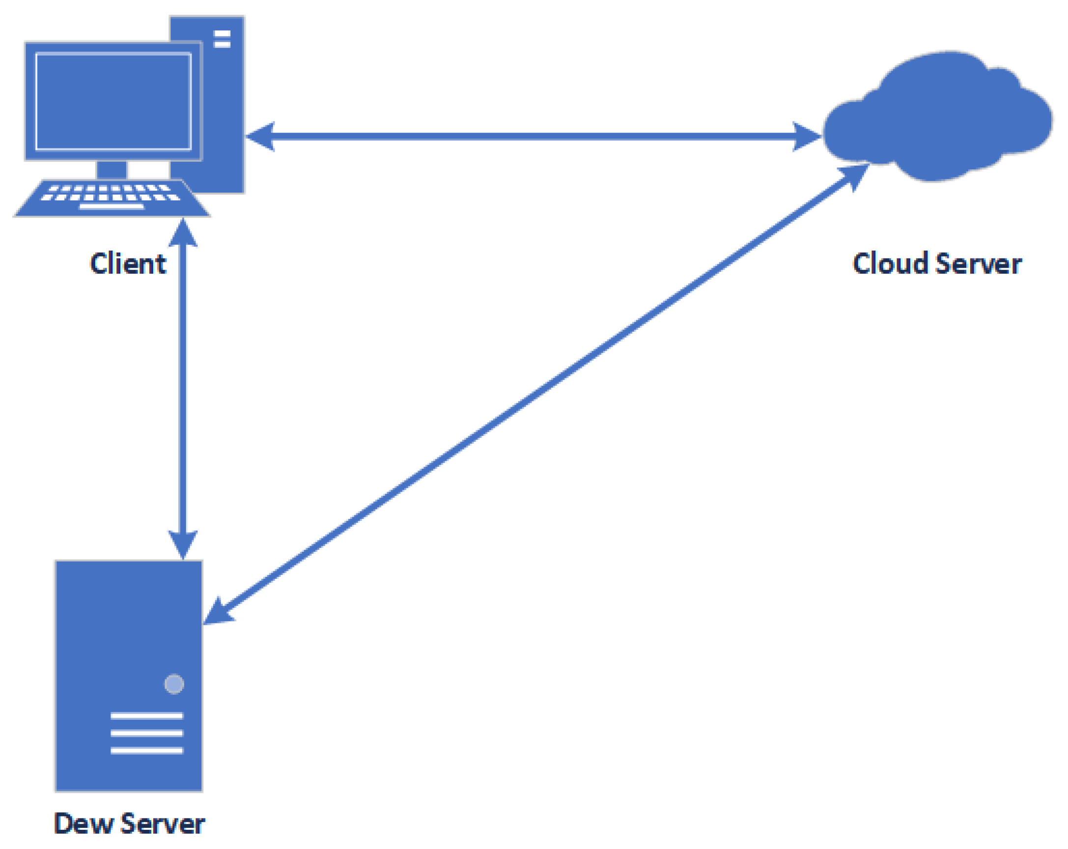
Multi-cloud storage relies on several cloud storage providers. These providers have to collaborate to provide storage service for users. Data is striped and sent to multiple cloud storage providers that are located in different geological areas. The data stored in multiple cloud storage providers may be duplicated from the original data or a part of it. This method improves fault tolerance, higher service availability, data durability, and bypasses vendor lock-in, as we discussed in the previous section. Single cloud storage relies on only one particular cloud storage provider. Users use the service via the given application from the provider on their devices. For single cloud developers, they quickly build systems and applications only over single cloud storage. They require only application programming interface (API) contributed by the cloud storage provider [19].
In contrast, there is no official application for using multiple cloud storage services. Users utilize third-party applications to consume the service. From the developer’s point of view, cloud application development is often not as easy as a single cloud application. Developers need to understand each cloud provider API structure and syntax. Additionally, they have to make them collaborate in order to perform multiple cloud storage services.
From the comparison, there is a trade-off between using single cloud storage and multi-cloud storage. Single cloud storage is easy to utilize, and it is easy to develop applications. However, there are several drawbacks, as already discussed. For multi-cloud storage, the system is more robust and secure than single cloud storage. However, it is hard to develop applications and is time-consuming. The development requires skilled developers. Additionally, data management is a complicated task.
Multi-cloud storage has begun to play a major role in the market. There are applications in e-health data storage for keeping and sharing sensitive health data of patients in hospitals [2,20].

3.2. Dew Computing

3.2.1. Definition

Dew computing is a model that links the core idea of cloud computing with the abilities of end devices. This computing is a new paradigm that fills the gap that cloud computing possesses. The gap is created by discontinuing cloud services while the internet is down. When the internet is out of service, the user loses connection to the cloud and cannot use its services. Dew computing provides temporary service to manage and allow the user to continue his or her usage.
Dew computing was defined in start at 2015 Wang as follows: “Dew computing is a personal computer software organization paradigm in the age of cloud computing. Its goal is fully to realize the potentials of personal computers and cloud services. In this paradigm, software on a personal computer is organized according to the Cloud-dew Architecture; in this paradigm, a local computer provides rich functionality independent of cloud services and also collaborates with cloud services”. The first version of the dew computing definition is presented in [21]. The definition emphasizes that dew computing operates on a personal computer. A personal computer follows cloud-dew architecture. additionally, a local computer provides functionality and collaborates with cloud services.
Wang refined the definition: “Dew computing is an on-premises computer software–hardware organization paradigm in the cloud computing environment where the on-premises computer provides functionality that is independent of cloud services and is also collaborative with cloud services. The goal of dew computing is to fully realize the potentials of on-premises computers and cloud service”. The refined version of the dew computing definition presented in [6]. This definition extends the first definition. It does not only emphasize a personal computer. It includes various computer types from smartphones to high-level computers such as mainframes and servers. The second definition defined them as on-premises computers that operate independently and collaboratively with cloud services.
Recently, Partha [22] proposed a new definition of dew computing: “Dew Computing is a programming model for enabling ubiquitous, pervasive, and convenient ready-to-go, plug-in facility empowered personal network that includes Single-Super-Hybrid-Peer P2P communication link”. Its main goal is to access a pool of raw data equipped with meta-data that can be rapidly created, edited, stored, and deleted with minimal internetwork management effort (i.e., offline mode). It may be specially tailored for efficient usage, installation, and consumption of local computing (i.e., on-premises) resources like PC, Laptop, Tablet, high end Smart Phone. This computing model is composed of six essential characteristics such as. Rule-based Data Collection, Synchronization, Scalability, Reorigination, Transparency, and Any Time Any How Accessibility; three service models such as Software-as-a-Dew Service, Software-as-a-Dew Product, Infrastructure-as-a-Dew; and two identity models (e.g., Open, Closed). All such efforts shall be made towards running of applications in a purely-distributed and hierarchical manner without requiring continuous intervention from remotely located central communication point e.g., cloud server, etc." The latest definition is polished and adds six essential characteristics.
Dew computing can be used for indoor/outdoor applications and life-related scenarios, for example, smart houses, smart offices, and smart health care. The devices in cloud computing are not limit to personal computers or high performance computing devices; for example, in [23] mobile devices were integrated as primary computing providers to a dew computing environment.

3.2.2. Comparative Analysis of Fog and Dew Computing

Fog computing was proposed by Vice President of Cisco System, Flavio Bonomi, in September 2011. Ref. [24] Fog computing is a scenario where a vast number of heterogeneous (wireless and sometimes autonomous) ubiquitous and decentralized devices communicate and potentially cooperate among them and with the network to perform storage and processing tasks without the intervention of third-parties. Fog computing extends cloud computing and its services to devices such as routers, routing switches, multiplexers. It includes automation devices because fog computing was proposed with the Internet of Things (IoT) as its environment. However, automation devices usually have computing power, but they are not operated directly by human users when they are in normal operations.
Meanwhile, dew computing brings processing close to users. Dew computing was proposed in 2015. The dew computing definition is as mentioned in Section 3.2.1. The goal of dew computing is to realize the potential of on-premises computers and be fully capable of cloud services. While cloud computing uses centralized servers to offer its services, dew computing presents on-premises computers to provide distributed, cloud-friendly, and collaborative micro-services to end-users.
Both computing models have a common feature. Fog and dew computing bring computing powers at location that are closer to users. Nevertheless, it is hard to discover the exact variations among these computing models through their definitions. Usually, a computing model was proposed to solve a specific problem. Fog computing is tightly related to the Internet of Things, emphasizes proximity to end-users and client objectives. The IoT hardware are dense geographical distribution, local resource pooling, latency reduction, and backbone bandwidth savings. Dew computing is more related to software design. The strong point of dew computing is to encourage helpful for new applications to be developed. Dew computing was proposed to solve the data availability problem when an Internet connection is not available. Other than that, dew computing does typically not involve edge devices such as routers and switches.
If applications are related to IoT research or the IoT industry, fog computing is the area developers should pay attention to. A massive amount of sensors will be expanded everywhere. The best place for computing powers to process data from these sensors should not be far away from cloud servers or low-capacity sensors. The network devices such as, routers or switches, are a better choice. If the applications are in the design of novice distributed applications, dew computing could bring developers with revelations and constructive assistance. Dew computing does not include edge devices, such as routers and switches; the network topology does not restrict dew computing. Table 1 shows the summarize of comparative analysis between fog and dew computing.
The dew server connects to each cloud storage via micro-service. Each micro-service connects to each cloud storage, as shown in Section 4.3.1. The micro-service is a pluggable software that can install or remove from the dew server.
From Cloud-Fog-Dew Computing Hierarchy, fog computing can be considered close to cloud computing while dew computing is close to users. Fog servers are representing high-level servers situated in front of the clouds. However, dew computing surpasses beyond the concept of a network/storage/service, to a sub-platform. The dew computing is based on a microservice concept in computing hierarchy. Dew computing shifts the boundaries to computing applications, data, and low-level services away from centralized virtual nodes to the end-users [27].
We can look at another point of view. Fog computing works as a back-end layer. It is hard to access or configure from users. Alternatively, dew computing works as a front-end layer. It is easily accessible by users and easy to modify or configuration because dew computing is software basics [28].
From the application point of view, fog computing suit receives data that streaming data sources from sensors or other network hardware automatically. However, data from file-sharing schemes are static and not always streaming all the time. Data transferring occurs when users ask and authorized to download data. However, it does not mean fog computing is not suitable for file sharing scheme. Plainly, it is high-priced and not flexible when balance with dew computing.

3.2.3. Dew Computing Components

Figure 1 shows the structure of the dew computing concept. Dew computing acts as a middleman or buffer between cloud computing and user devices.
The core structure of dew computing is a cloud-dew architecture, depicted in Figure 2. It is an extension of classical architecture and client-server architecture. In a client-server architecture, a server is a central and high-performance machine that clients connect so as to utilize its services. A cloud-dew architecture, it has two main components; dew server, and dew site [29].
From Figure 2, a local computer consists of a client program, a dew server, a database management system, and a database. The dew server is a web server that is installed on a user’s local computer. The dew server and its components provide a similar service as a cloud server offer. It also updates data in the local database along with the cloud server database so that it has the same content.
The dew server has the following features:
  • A dew server is a lightweight web server. It provides service to only one client or user. Therefore, it does not require a high-performance machine.
  • The storage capacity of the dew server is smaller than the storage capacity of the cloud storage provider. The data, stored on a dew server, belongs to a particular user.
  • A dew server may die out immediately. The reason for disappearance may be caused by hardware failure or software virus infections.
  • A vanished or damaged dew server can be restored quickly because all dew server data has a back up in the cloud servers.
  • A dew server can be accessed although the internet connection is lost because it is operating on the local computer.
The dew server can be used when the internet connection is lost and the user can access his or her cloud service. Users can continue to use local service as if they are using the cloud service. The duplicated website in a dew server (called a dewsite) and the original website could be different in the following aspects:
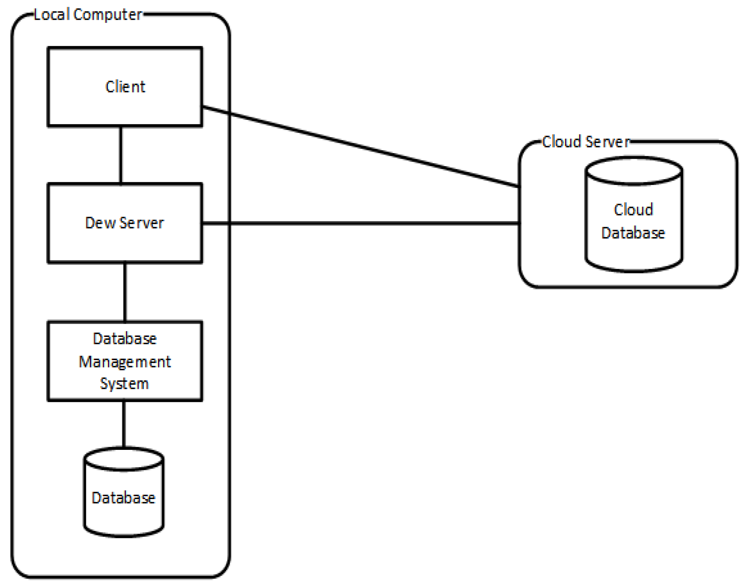
  • The dewsite operates with a light load. Therefore, the dewsite is less complicated than the website.
  • The dewsite uses open technology in its implementation rather than scripts that the website wants to conceal.
  • A dewsite database content and capacity are limited.
  • A new function will be added on both websites and dewsites synchronously.
In this paper, we apply the idea of a cloud-dew architecture for file fragment management in multiple cloud storage, which will be discussed in the next section.

3.3. Distance Base Encryption

Ref. [30] The biometric-based encryption uses a distance-based encryption and a recognition algorithm. The recognition algorithm generates a universal threshold value and distance parameters to measure the difference of vectors. These vectors originate from the biometrics of correspondent users. If the distance of the two vectors is less than the threshold value, then both biometrics are considered as a “match”. The decryption condition follows the result of vector recognition. If the distance between vector x and y is less than or equal to threshold value t u , we can interpret the two biometrics as a match. The corresponding private key can decrypt the corresponding ciphertext. In this algorithm, biometrics are used as public identities. Any encryptor can receive the decryptor’s biometrics for encryption.
The distance-based encryption (DBE) is composed of three entities: a private key generator (PKG), an encryptor, and a decryptor.
  • P K G : The private key generator is the trusted third party that computes the private keys of biometrics for users. Users have to register their biometrics and are verified by the PKG. The PKG will generate private keys for users. The PKG receives the registered biometric and a master secret key as input. It then creates a vector y from the recognition algorithm and a private key for the user from the key generation algorithm.
  • E n c r y p t o r : The encryptor is a message sender who wants to send a sensitive message to a receiver, where the message is encrypted with the receiver’s biometrics. First, the recognition algorithm is called to extract vector x of this biometric. The encryption algorithm then encrypts the message using x and a threshold value t u . The encryptor set t = t u , which means the encryptor wants the decryptor to have a private key vector y close to x under the official recognition. If t < t u , the encryptor wishes the decryptor to have a private key on a vector y close to x .
  • D e c r y p t o r : The decryptor receives a ciphertext sent from the encryptor and private key y as input. If the distance between x and y is less than or equal to t, the decryptor can decrypt the given ciphertext. It is necessary to process further biometrics because both biometrics are transformed into vectors already.
The algorithm of distance-based encryption begin with defining the squared Mahalanobis distance. It defines as
d ( x , y ) = 1 i , j n f i , j ( x i y i ) ( x j y j )
We define variables X , Y , f i ( x ) , f i ( y ) as following
X = 1 i , j n f i , j x i x j
Y = 1 i , j n f i , j y i y j
f i ( x ) = j = 1 n f i , j x j
f i ( y ) = j = 1 n f i , j y j
Let w and z are two vectors which have ( 2 n + 2 ) length.
w = ( x 1 , x 2 , , x n , f 1 ( x ) , f 2 ( x ) , , f n ( x ) , X , 1 )
z = ( f 1 ( y ) , f 2 ( y ) , , f n ( y ) , y 1 , y 2 , , y n , 1 , Y )
Then,
d ( x , y ) = 1 i , j n f i , j ( x i y i ) ( x j y j ) = X + Y + i = 1 n x i f i ( y ) + i = 1 n y i f i ( x ) = w , z .
The inner product of vector transformation equals to zero iff d ( x , y ) = 0 . In order to get zero inner product for all d ( x , y ) t , define w l 1 , z l 2 from x , z with l 1 , l 2 .
w l 1 = ( x 1 , x 2 , , x n , f 1 ( x ) , f 2 ( x ) , , f n ( x ) , X l 1 , 1 )
z l 2 = ( f 1 ( y ) , f 2 ( y ) , , f n ( y ) , y 1 , y 2 , , y n , 1 , Y + l 2 )
We earn the relationship between the inner product and the squared Mahalanobis distance.
w l 1 , z l 2 = d ( x , y ) + l 2 l 1
After we define the Mahalanobis distance and perform the Inner Product Encryption, the Distance Base Encryption is designed for ( 2 n + 2 ) -length vectors as follow. Let PG = ( G , G T , g , p , e ) be the symmetric bilinear pairing groups, where G is an elliptic subgroup and G T is a multiplicative subgroup. Both two groups are of the same prime order p.
g is a generator of G . e is the bilinear map capturing the three properties:
  • e ( g a , h b ) = e ( g , h ) a b for all g , h G , a , b Z p
  • e ( g , g ) is a generator of G T
  • It is efficient to compute e ( g , h ) for all g , h G .
The setup phase of DBE begins with receiving security parameter λ and length of vector n as input. Firstly, we choose PG = ( G , G T , g , p , e ) . Then, the algorithm randomly select α i , β from Z p for all i = 1 , 2 , , n . Finally, it computes group elements g i = g α i and u = e ( g , g ) β . The output from setup phase are master public key ( IPE . mpk ) and the master secret key ( IPE . msk ),
IPE . mpk = ( G , G T , g , p , e , g i , u ) IPE . msk = ( α 1 , α 2 , , α n , β ) .
The next phase is key generation. This phase takes n-length vector z = ( z 1 , z 2 , , z n ) Z p n and master public/secret key from the setup phase. The algorithm select t Z p and calculate for the private key IPE . sk z ,
IPE . sk z = ( g β + t i = 1 n α i z i , g t ) G × G .
The third phase is encryption phase. The message is encrpted by the encryption algorithm. The input of the algorithm are n-length vector w = ( w 1 , w 2 , , w n ) Z p n , and the master public key. The algorithm randomly select r , s from Z p . The cipher text is created,
IPE . CT = ( u r · M , g r , g 1 r g s w 1 , g 2 r g s w 2 , , g n r g s w n )
The final phase is decryption phase. The ciphertext, IPE . CT = ( C m , C 0 , C 1 , , C n ) , is decrypted in this phase to get original message. The ciphertext, encrypted with w , and private key, for z where w , z = 0 , are input for this phase. The decryption process begins with e 0 = e ( g t , i = 1 n C i Z i )
e 0 = e ( g t , i = 1 n C i Z i ) e 1 = e ( g β + t i = 1 n α i z i , C 0 ) .
Then, the algorithm computes the decrypted message
C m · e 1 1 e 0 = M .
When w , z = 0 , the decryption is correct,
e 0 = e ( g t , i = 1 n C i z i ) = e ( g t , i = 1 n ( g i r g s w i ) z i ) = e ( g , g ) r i · i = 1 n α i z i + s t · i = 1 n w i z i e 1 = e ( g β + t i = 1 n α i z i , C 0 ) = e ( g β + t i = 1 n α i z i , g r ) = e ( g , g ) β r · e ( g , g ) r t i = 1 n α i z i C m · e 1 1 e 0 = u r M · e ( g , g ) β r · e ( g , g ) r t i = 1 n α i z i · e ( g , g ) r t i = 1 n α i z i + s t w , z = e ( g , g ) β r M · e ( g , g ) β r · e ( g , g ) s t w , z = M · e ( g , g ) s t · w , z = M

4. Approach

4.1. Problem Formulation

This paper focuses on the privacy and security protection of the big data file sharing. The file owner wants to limit the file accessibility only for authorized users. The original files are categorized into two groups: sensitive and insensitive [31,32]. The sensitive files are divided into fragments and then encrypted before each fragment is deployed to cloud storage—one fragment per cloud storage provider. This situation means one cloud storage device holds only one copy of the file fragment. The insensitive files are also divided without encryption before fragment deployment.
The primary purpose of an attacker is to reconstruct the original file from stolen fragments. The attacker has to breach the security of the cloud storage provider, access the file location and obtain a sufficient amount of correct of pieces of the target file. However, it is hard for the attacker to retrieve some or all of the fragments from every cloud storage location.
There is only one requirement in reconstructing the original insensitive files. Users or attackers have to possess complete fragments of the original file and combine them. For sensitive files, users or attackers require two components: the complete fragments and the encryption key to decrypt the fragments before combining them.

4.2. System Architecture

Figure 3 shows our proposed architecture for file distribution on a multi-cloud. This method ensures that the file cannot obtain access without the knowledge or permission of the owner. The data owner prepares the original files to upload via the client of the framework in the data owner’s machine. He or she selects which files are sensitive or insensitive. For sensitive files, he or she divides them into fragments, then encrypts them with his or her secret key. For insensitive files, the data owner divides the files without encryption. Each fragment is initially stored in the data owner’s machine and then uploads it to the multi-cloud storage providers. Afterward, the metadata which contains the fragment location is created. When a user wants to access or use the files, the user sends the request to the data owner via the client from the user’s machine. After the data owner receives the request, and he or she approves it, the data owner will share his or her credentials through a secure communication channel. The user keys in the credentials through the framework client, and the client on the user’s machine directly connects to each cloud storage based on the fragment location from the metadata and downloads them. When the fragments are completely downloaded, the client will decrypt the fragments and merge them into the original file in the case of a sensitive file. In case of an insensitive file, the decryption is skipped.
The proposed architecture contains the following entities: the data owner, the dew server, the cloud storage providers, the key management unit, and the data user.
  • Data owner: The data owner is the person who keeps the original data file and holds the authorization for users who want to access those fragments of a data file. The data owner sends an authorized token to the user. The token contains fragment information such as username, password, and location.
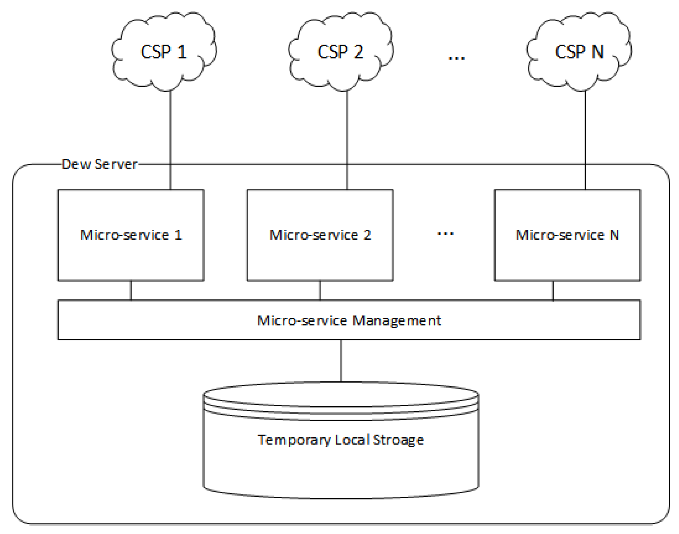
  • Dew server: A dew server is a lightweight server that manages data fragments, accessing requests, and authorization token transfers, and temporarily stores some file pieces when CSPs are out off services.
  • Cloud storage provider: The cloud storage provider offers storage service for customers. Each cloud storage provider has its policies, service offerings, costs, and connection methods.
  • Key management unit: The secret key may be stored in the data owner’s local machine, a third party’s key management server, or a cloud provider data center. In our approach, the private key is on the owner’s premises so as to improve flexibility and enable file sharing.
  • Data user: A data user is a person who needs to use the sharing file in multi-cloud storage. The user must be granted by data owner authorization from the data owner before accessing the file fragments in cloud storage.
  • Data owner’s machine: All of the uploading operations are processed in this machine, including file slicing, fragments encryption, and fragment uploading. Additionally, the key management process is operated on the local machine.
  • Data user’s machine: When all fragments are downloaded, the fragments are decrypted and merged in the user’s machine.

4.3. System Design

This section discusses how the proposed system is designed. We provide more details about how the data is processed before uploading it to cloud storage providers, data reconstruction on the user’s side, and the system management drive by the dew server.

4.3.1. Dew Server

In the proposed scheme, we implement the concept of Storage In Dew (STiD) [6]. Our dew server is a personal computer that hosts cloud storage micro-services in term of cloudlets or small services run on a web server. Each micro-service connects and communicates to each cloud storage provider. However, the dew server has not only communicated with the cloud storage function but also performs other functionalities.
  • User Management: The dew server monitors incoming requests whether they are from registered users or not. The dew server has a responsibility to register new users and create their private key.
  • Fragment Monitoring: The dew server monitors file fragments’ availability. If some fragments do not appear in cloud storage, the dew server will notify the data owner about these missing fragments. The data owner then uploads the missing fragments to the corresponding cloud storage.
  • Temporary Fragment Hosting: When cloud storage services are offline, the file fragment hosted on those cloud storage providers cannot be accessed. The data owner may upload the missing fragments to the dew server. The users are switched to download from temporary storage until the CSPs are online again. However, the dew server does not contain complete fragments due to the size of the whole file is more extensive than the dew server storage space. It just temporarily host some file fragments.
The micro-services are installed on the dew server. One micro-service on the dew server serves one cloud storage provider, as shown in Figure 4. Each micro-service takes responsibility to monitor the availability of the fragment stored in the CSP. The data owner may change the file hosting service from one CSP to a new one. To add a new storage service, the dew server installs the micro-service that support particular CSP. When a hosting service cancels from a CSP, the dew server only removes the particular micro-service from the dew server or leaves it on dew server for future use.
We can implement the micro-service in two ways. First, micro-services can be run as a service on an application server, and can be implemented by traditional web programming languages such as PHP or Java. If we have a high-performance machine, we can implement micro-services as virtual machines, one VM per CSP, and run them on a hypervisor [33].
When users lose communication with the cloud storage, or some cloud fragments are unavailable on a dew server, the temporary fragment hosting feature will be activated. The data owner will be notified of the missing fragments by the dew server. To fix the problem, he or she will upload the missing fragments to cloud storage, whether the clouds are new or old. At the same time, the data owner uploads the missing fragments to the dew server. The client from the user device will connect to the dew server to download missing fragments. The dew server then transfers the fragments to user clients.

4.3.2. Fragment Deployment

This section explains the data pre-processing step before the data owner deploys his or her pieces of the file to cloud storage. In order to preserve privacy, all sensitive files are divided and encrypted before they are deployed to multi-cloud storage.
In Algorithm 1, the data owner chooses which file is sensitive or insensitive. The sensitive file is a file that contains valuable information about the data owner. It must not be leaked to unauthorized people. Therefore, the data owner encrypts this kind of file before outsourcing to cloud storage. Our scheme uses the AES algorithm to encrypt sensitive fragments. On the contrary, the insensitive file is general information or unharmed information. It can be leaked to general people. Even if it is retrieved by unauthorized people, the information inside is not exposed nor does it harm the data owner. There fore, it is necessary to encrypt it.
A metadata file is then created and stored in local storage. The metadata is a place to keep authorization information. It is used as a major component for the right users to access the file fragments and combine them to produce the original file. The details of the metadata are shown in Table 2.
Algorithm 1 File Splitting and Fragment Encryption
  Input: Original file (F), owner’s secret key ( S k )
  Output: File fragments ( F 1 , F 2 , , F N ) or Encrypted file fragments ( E n ( F 1 ) , E n ( F 2 ) , , E n ( F N ) )
procedure FileSplitEncrypt
   if I s S e n s i t i v e ( F ) = t r u e then
    Estimate file size
    Divide file into fragments to an equal number of cloud storage providers (N)
    Give fragments a file name based on the order of fragments on the owner’s machine
    Encrypt each fragment by the AES algorithm with the owner’s secret key
    return E n ( F 1 ) , E n ( F 2 ) , , E n ( F N )
   else
    Estimate file size
    Divide file into fragments to an equal number of cloud storage providers
    Give fragments a file name based on the order of fragments on the owner’s machine
    return F 1 , F 2 , , F N
   end if
   Upload each fragment to multi-cloud storage.
end procedure

4.4. Cloud Selection

In order to achieve optimal performance at an affordable price, we optimize storage expenses for file fragment uploading, which is a payment for the data owner. Additionally, the user cannot retrieve the fragments in an inappropriate time. Therefore, we formulate our problem to multi-objective optimization problem, c 1 and c 2 . The first objective is to minimize the storage cost of fragments hosting in CSPs. The second objective is to minimize the download time of a user. The solution to this optimization problem is a set of N CSPs selected from K available CSPs. Let X = { x 1 , x 2 , , x K } is a set of available CSPs and x X .
min c 1 ( x ) = i = 1 N x j f i k i
min c 2 ( x ) = i = 1 N x j f i v i
where j { 1 , 2 , , K } , subject to
j = 1 K x i = K , x j ( 0 , 1 )
i = 1 N f = | F |
i = 1 N v i u ( S )
The first objective is to try to reduce storage costs as much as possible. The storage cost is the multiplication of the data unit stored on a particular cloud provider, f, and the price per data unit on a particular cloud provider, k i . Therefore, the total cost is f k i .
The second objective is to reduce the download time for a user. The download time for a file fragment from a particular CSP is the multiplication of a fragment data unit, f, and the upload rate of the hosting cloud provider, v i . Therefore, the total download time is f v i . In this objective, we assume the second case of Theorem 1, d m i n > u ( S ) , in which the download rate of the user is greater than the aggregate upload rate from a set of CSPs, which we will discuss in Section 5.2.
There are three constraints for this problem. The first constraint is that the total number of available cloud storage provider equals K providers. We cannot select other cloud providers than in the available CSP set, X . The next constraint is the fragment size stored on a particular cloud equal to | F | N . Since we equally divide file F into N fragments, the total sum of the fragment size does not exceed the size of the original file. The final constraint is the total upload rate from each seeder (CSP) to a leecher (a user who is downloading) is less than the aggregate upload bandwidth of seeders.
This section is related to the execution of a user requests for outsourced fragments, and the aggregation of the outcomes is depicted in Algorithm 2.
Algorithm 2 File Merging and Reconstructing
  Input: File Fragments ( F 1 , F 2 , , F N ) or Encrypted File Fragments ( E n ( F 1 ) , E n ( F 2 ) , , E n ( F N ) ), Encrypted Secret key ( E n ( S k ) )
  Output: Decrypted file fragments and merged to original File(F)
procedure FileMergeReconst
   Get the fragment details and encrypted secret key ( E ( S k ) ) from the file owner
   Decrypted E n ( S k ) to obtain S k
   if D e ( E n ( S k ) ) = t r u e then (Algorithm 3.)
    Get secret key, S k
   else
    End procedure
   end if
   for each cloud storage i do
    Search file fragment
    Download file fragment ( F i or E n ( F i ) )
   end for
   if I s S e n s i t i v e ( ) = t r u e then
    for each fragment i do
     Decrypt fragment E n ( F i ) by S k and obtain F i
    end for
   end if
   Merge fragments F 1 , F 2 , , F N to obtain original file F
   Automatically remove file fragments and the secret key from the user’s machine
   return Original file (F)
end procedure

4.5. Fragment Retrieval and File Reconstruction

The section related to the execution of a user task for outsourced fragments, and the aggregation of the outcomes is depicted in Algorithm 2.
First, the user sends a request to the dew server via a client on his or her device. The request is then transferred to the data owner, who will grant the incoming request. If the request is granted, the data owner will send the metadata and the secret key encrypted by Distance-Based Encryption via the dew server or other communication channel selected by the data owner. The client on the user’s device decrypts the received message for the secret key and metadata. If the decryption fails, the process stops. This situation means that the biometric of the requester is not matched with the user biometric, which is registered in the framework. If the decryption is successful, the client will use connection information from the metadata to directly communicate to each CSP for fragment downloading. For each CSP connection, the user’s client uses authorization information to access and download the corresponding file fragment to the user’s device.
All fragments are then entirely downloaded. They will be decrypted and combined with risk items according to the condition used to split them and provides the complete original file to the user. However, if the downloaded fragments are insensitive file fragments, the framework will skip the decryption process.
The combination of the secret key and metadata are generated by the data owner and kept locally on the data owner’s device. They are not provided on CSPs or even the dew server. Users receive these items only during downloading and regenerate the original file. After the original file is created, risk items and metadata are deleted from the user’s device automatically. We called this scheme an Asymmetric Security Scheme.

4.6. Secret Key Encryption and Decryption

Based on Distance-Based Encryption, in Section 3.3, we designed a procedure to establish a communication key between the data owner and the requested users.
Algorithm 3 represents how the secret key and metadata are sent to users. Both the secret key and the metadata are encrypted by an encryption algorithm to produce ciphertext, C T . In order to decrypt the ciphertext to message M, the biometric vector y from the receiver side must have a distance that is less than the threshold value t. Otherwise, the users cannot encrypt the ciphertext to obtain the secret key and the metadata.
Algorithm 3 Key Communication.
procedure KeyCommunicate [30]
   Setup: The setup algorithm takes as input the security parameter λ and distance parameters ( m , F ). It returns a master public/secret key pair ( m p k , m s k ).
   KeyGen: The key generation algorithm takes as input the data owner secret key m s k and a user’s biometric n-length vector y . The alogirthm then returns a private key S k y for y .
   Encryption: The encryption algorithm uses m p k , an n-length vector x , a threshold value t, and a message M. The result is ciphertext, C T = En[ x , t , M ].
   Decryption: The input of decryption are ciphertext ( C T ), the master public key ( m p k ), and the private key S k y .
     if d ( x , y ) t then
       The decryption is successful: return message M.
     else
       The decryption fails, and the procedure stops.
end procedure

5. Analysis

This section analyzes the character of the proposed architecture in two aspects: security and performance analysis.

5.1. Security Analysis

In our architecture, the data file is categorized into two types: insensitive and sensitive. As we discussed earlier, the insensitive file contains no valuable content. They can be leaked or revealed to unauthorized users or attackers with no effect on or harm to, the identity of the owner himself.
The file fragments of the insensitive type can be stored freely in multi-cloud storage. It contains the content of the file, such as text, a database, pictures, voice, or video. On the other hand, the sensitive fragments contain essential content. If they are leaked or revealed to unauthorized users, they will harm the data owner. Therefore, the sensitive file type is stored with protection by encryption.
Comparing this scheme with single cloud storage, if an insider attack occurs in the CSPs, the attacker will retrieve the whole data file at one attack. In contrast, if there is an insider attack of a CSP in our scheme, the attacker will retrieve only a part of the data file, which is useless for the attacker that holds only one or some pieces of the data file. The attacker has to attack each cloud storage provider in order to retrieve the complete data file.
The secret key and metadata retain the storage index information for each fragment, file structure, file header, and decryption method. It is similar to a treasure map guide user to all data parts. Additionally, these are the most crucial part of the original file reconstruction. The user must have this part from the data owner, along with file fragments, form each cloud storage in order to reconstruct the original data file.
As the owner, he or she holds the storage path (contained in the metadata) confidentially. The data owner may store this part locally on his or her machine or another machine on his or her behalf. Even the attacker retrieves some data parts, he or she cannot reconstruct or interpret the original data file without the secret key and metadata. The data owner will send them to the authorized user who requests to access his or her file fragments on multiple cloud storage.
We define a big data file as F. The F is split into N fragments { F 1 , F 2 , …, F n }. In this research, each fragment has only one copy. The reason behind this idea is to save storage space, i.e. save the cost of service usage. Each copy is hosted on each cloud storage provider. The cloud storage servers store file fragments with encryption for sensitive file fragments and without encryption for insensitive file fragments, represented by F i . The attacker needs to break into n servers, each storing a fragment of file F i to comprise the whole file.
We consider the security of our scheme in two scenarios. The first scenario is where the attacker a knows the storage path of all fragments. The second scenario is where the attacker a does not know the storage path of the fragments. In both scenarios, the attacker has different ways to retrieve file fragments.

5.1.1. Attacker Knows the Storage Path

Ref. [34] Let a be an attacker who desires to obtain the storage path of the big data file illegally. According to our proposed scheme, the attacker can reclaim the entire big data file only when he or she knows the storage paths of all fragments. Therefore, the security of fragment storing can be evaluated by assessing the probability that a knows the storage paths of all fragments.
In the proposed scheme, big data is separated into n fragments, and these n fragments are stored at n different cloud storage providers. We assume that the attacker a can know the storage paths of the parts of big data in cloud i with probability p a i , when 0 < p a i < 1 . In this case, the probability that attacker a may retrieve all the storage paths of the file fragments is
P 1 = i = 1 n p a i
When the value of the probability p a i is low, and the number of fragments n is high enough, the probability P 1 is extremely low.

5.1.2. Attacker Does Not Know the Storage Path

In the second scenario, the attacker does not know the storage paths. The only way to retrieve all fragments is to breach the security of m cloud storage, where n m . The attacker does not know which n clouds from m clouds store the right n fragments. Let p b be the probability that attacker a select the right n clouds from m to attack.
p b = number of select correct n out of n clouds number of select correct n out of m clouds = n n m n = n ! ( m n ) ! m !
Suppose, the attacker selects the right n clouds. Each cloud storage contain fragments of other users. We assume cloud i contains s i fragments. For each attack, the attacker retrieve r i fragments, where r i s i . There is only one target fragment store on the cloud. Theerefore, let p c i be the probability that r i fragments contain the target fragment. Therefore,
p c i = s i 1 r i 1 s i r i = r i s i
which is the extended case of our previous work [35]. That work considered only when the attacker retrieves only one fragment per each attack.
For the second scenario, let P 2 be the probability that attacker a regains all target fragments without the knowledge of storage paths.
P 2 = p b i = 1 n p c i
Substitute p b from Equation (2) and p c i from Equation (3) into Equation (4), we acquire
P 2 = ( m n ) ! m ! i = 1 n r i s i
There are at least two requirements that the attacker must achieve to retrieve all fragments correctly. First, he or she has to select the right n clouds that store target file fragments. Second, even if he or she correctly selects n clouds, he or she has to retrieve the number of fragments on those clouds that contain target file fragments. Moreover, he or she must possess the secret key from the data owner to decrypt the sensitive file fragments. We can say that the probability that the attacker will retrieve all fragments from the proposed scheme is very low.

5.2. Performance Analysis

The proposed architecture is a hybrid between client/server architecture and peer-to-peer architecture. Authorized users download file fragments from CSPs. In this section, each CSP acts like a seeder. We use the term “seeder” to represent CSP, and each user client acts like a leecher in a peer-to-peer architecture. We use the term “leechers” for user clients. However, there are different characteristics between our architecture and peer-to-peer architecture. First, seeders in the proposed work make no data transfer contribution among seeders. Each seeder only uploads its stored fragment to user clients. Second, leechers or user clients perform only downloading functions and do not transfer data among leechers.
To formalize the performance analysis, we define the relevant components. There are two sets of components for file distribution: seeders and leechers. We define a set of seeders as S and a set of leechers as L. Each seeder has a file fragment of size F P = | F P N | , since the file F P is equally divided into N pieces. Each leecher in L requires each of the fragments stored in the corresponding seeders. In the first stage, all of the leechers have no portion of the file fragments. As time passes, a leecher can obtain fragments of the file from any of the seeders. A leecher is permitted to leave after obtaining the entire file.
Let I = SL be the set of all elements in the system. Each element (seeder or leecher) i has an upload capacity u i , and each leecher has a download capacity d i . An element i can transmit bits of data at a maximum rate of u i and download bits of data at a maximum rate of d i . In real life today, the upload capacity or bandwidth is always less than the download capacity, which is u i < d i . Nonetheless, we assume arbitrary upload and download capacities in our analysis.
This section discusses the performance of the proposed architecture. In order to measure the performance, we measure it by a minimum distribution time. We have modified the relevant definitions in [36] to match our proposed architecture. The modified definitions neglect the data transfer contribution to the set of nodes. This means there is no data transfer from seeders to seeders or from leechers to leechers. The data transfer occurs only from seeders to leechers.
The distribution time is the time that all leechers take to retrieve the entire file. The rate profile is the rate at which leecher iL downloads ’fresh’ content from seeders at time t. [34] defines the rate profile as r i ( t ) , which t 0 , iL. Therefore, the minimum distribution time, T m i n , is the minimization of the distribution time achievable over all rate profiles.
As in [36,37], we define the assumptions.
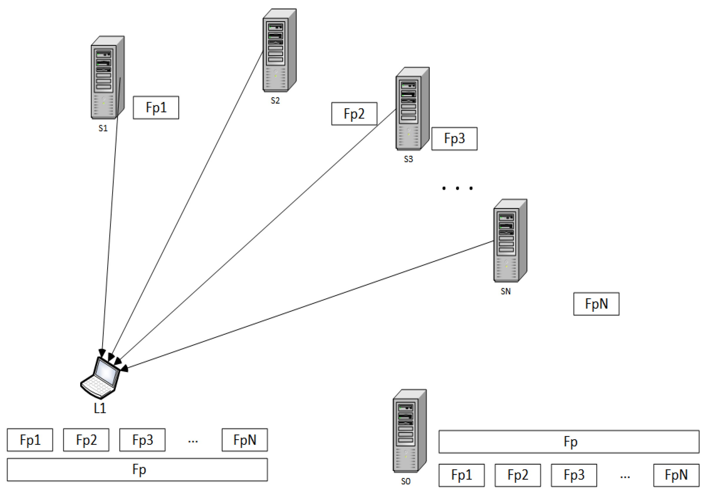
  • The bandwidth bottlenecks are not in the internet heart. They are only at the access end of the Internet, which is uploading and downloading points.
  • Both sets of seeders and leechers participate in file transferring until they completely retrieve all file fragments. There is no extra join or leaving companions between the process.
  • Seeders have a constant upload capacity. In addition, leechers have a constant download capacity.
  • At the first step, all seeders save all file fragments, while the leechers contain none of them.
  • Leechers focus only on downloading interested file fragments during the file transfer. Leechers do not cooperate in downloading other irrelevant files.
We set the notation:
  • the set of seeders is S = { s 1 , s 2 , , s N } ;
  • the set of leeachers is L = { l 1 , l 2 , , l M } ;
  • the number of seeder | S | = N ;
  • the number of leecher | L | = M ;
  • for the set of seeder set S, u ( S ) is the aggregate upload capacity, where u ( S ) = j S u j ;
  • for the set of leecher L, d m i n is the minimum download capacity, where d m i n = min i L d i
  • for subset L L , T m i n ( L ) is the minimum distribution time of leechers in subset L
In order to determine T m i n for our proposed architecture, we have to consider some details. First, the leecher with the slowest download speed is not able to retrieve the file fragments faster than F P d m i n . Second, the set of seeders cannot distribute current data at a rate faster than u ( S ) , and a leecher cannot receive the file fragment at a speed faster than u ( S ) . However, a set of seeders has to transfer the total amount of data equal to M F P to M leechers, implying T m i n > M F P u ( S ) . Thus, we achieve the lower bound for our file fragment distribution:
T m i n max { F P d m i n , M F P u ( S ) }
Theorem 1.
The minimum distribution time for the general heterogenous file distribution system is
T m i n = F P min { d m i n , u ( S ) M }
Proof of Theorem 1.
This proof considers two cases:
  • Case 1: d m i n < u ( S )
  • Case 2: d m i n u ( S )
We use the rate profile as defined earlier. For each instance, we create a rate profile with the following details. Each leecher i receives the file fragments from a set of seeders at a speed less than its download capacity d i , as shown in Figure 5. L1 is the user’s device that parallels connections to CSPs ( S 1 , S 2 , , S N ) to download each of the file fragments ( F p 1 , F p 2 , , F p N ) . S 0 is the data owner’s device that keeps the original file.
  • Case 1: d m i n u ( S )
The first case is a situation when the download rate of the slowest leecher is less than the aggregate seeder upload bandwidth, u ( S ) . A set of seeders sends a different file fragments to each of the leechers i at the following rate:
s i ( t ) = u i , t 0
where u i is the upload bandwidth of the set of seeders to leecher i. In addition, the above rate profile can be supported by the seeds because
i L s i ( t ) u ( S )
However, it is clear that d m i n u ( S ) . Thus, a leecher i L will be downloading fresh content from a set of seeders at a rate equal to the slowest download leecher d m i n .
r i ( t ) = s i ( t ) = d m i n
The download speed can be preserved at each leecher for all time t. The corresponding distribution time for this rate profile is F P d m i n . Each leecher in a set of leechers can finish downloading file fragments before the slowest leecher can. That means the minimum distribution time is equal to the time that the slowest leecher needs to download all file fragments from the set of seeders. According to the inequality in Equation (6), this will imply that the minimum distribution time for Case 1 is T m i n = F P / d m i n .
  • Case 2: d m i n > u ( S )
In this case, the download rate of the slowest leecher is faster than the aggregate upload bandwidth of the seeders. The set of seeders sends the file fragments to each of the leechers for total M F P bits. Additionally, the rate profile can be supported by the seeds because
i L s i ( t ) u ( S )
Nevertheless, it is obvious that d m i n > u ( S ) . Hence, a leecher i L will be downloading brand new content from a set of seeders at a partitioned rate of aggregation upload bandwidth of seeders, u ( S ) . Since the other leechers are identical in downloading file fragments from the related set of seeders, the upload bandwidth is not assigned to one specific leecher. It is shared among them.
r i ( t ) = s i ( t ) = u ( S ) M
The download speed can be maintained at each leecher for time t until all leechers obtain all file fragments. The corresponding distribution time for this rate profile is M F P u ( S ) . According to the inequality in Equation (5), this will presume that the minimum distribution time for Case 2 is T m i n = M F P / u ( S ) .
For simplicity of analysis, we assume that all leechers finish the file fragments downloading at the same time.  □

6. Evaluation

In this section, we will evaluate the proposed scheme in both security and distribution time.

6.1. Security Evaluation

From Section 5.1.1, the first scenarios in Equation (1) can be simplified if the probability p a i = p . This situation means that the probability that attacker a knows that the storage path of each cloud i is equal to p. The P 1 is then
P 1 = p n
as mentioned in [32].
The graph in Figure 6 shows the effect of probability that the attacker knows the storage paths (p) and the number of fragments (n) and can retrieve all fragments from all storage locations. As the number of n increases, the value of P 1 decreases. If the attacker knows less information about storage paths, and the file is split and is stored in different locations, the likelihood that the attacker collects all fragments is nearly zero.
In the second scenario, Section 5.1.2, the probability that the attacker retrieves all fragments is expressed in Equation (5). We can simplify this equation by assuming that the number of fragments obtained by the attacker in each attack equals r fragments, and r i = r . The fragments that are stored in each cloud equal s fragments, and s i = s . P 2 is then simplified to
P 2 = ( m n ) ! m ! ( r s ) n
Mainly, the value of P 2 depends on the number of fragments (or the number of storage clouds that contain target fragments), n. n is a controllable factor by the data owner or the framework. Other factors, such as the number of clouds the attacker chooses to attack (m) and the number of fragments retrieved for each attack ( r i ), depend on the abilities of the attacker. The number of fragments stored in the cloud ( s i ) depends on each cloud storage.
Figure 7 is the line graph that compares the probability that the attacker might retrieve all fragments from cloud storage without knowledge of the storage path. Overall, the probability declines as the number of cloud attacks increases. We set the number of correct file fragments to 5 (n = 5). The fragments stored in each cloud storage device is 20 fragments (s = 20).
When the ability of fragment retrieval of each attack is 20 fragments (r = s = 20), and the attacker is lucky to choose correct cloud storage, which contains the correct fragment (m = n), the probability is equal to 1.0. The probability decline when the number of attacks is increased. This pattern is the same with other lines but different beginning value, and then the probabilities plunge near to zero. This situation means even the attacker can attack the correct clouds, and there is a likelihood that he cannot retrieve the right fragment among stored fragments on the clouds.

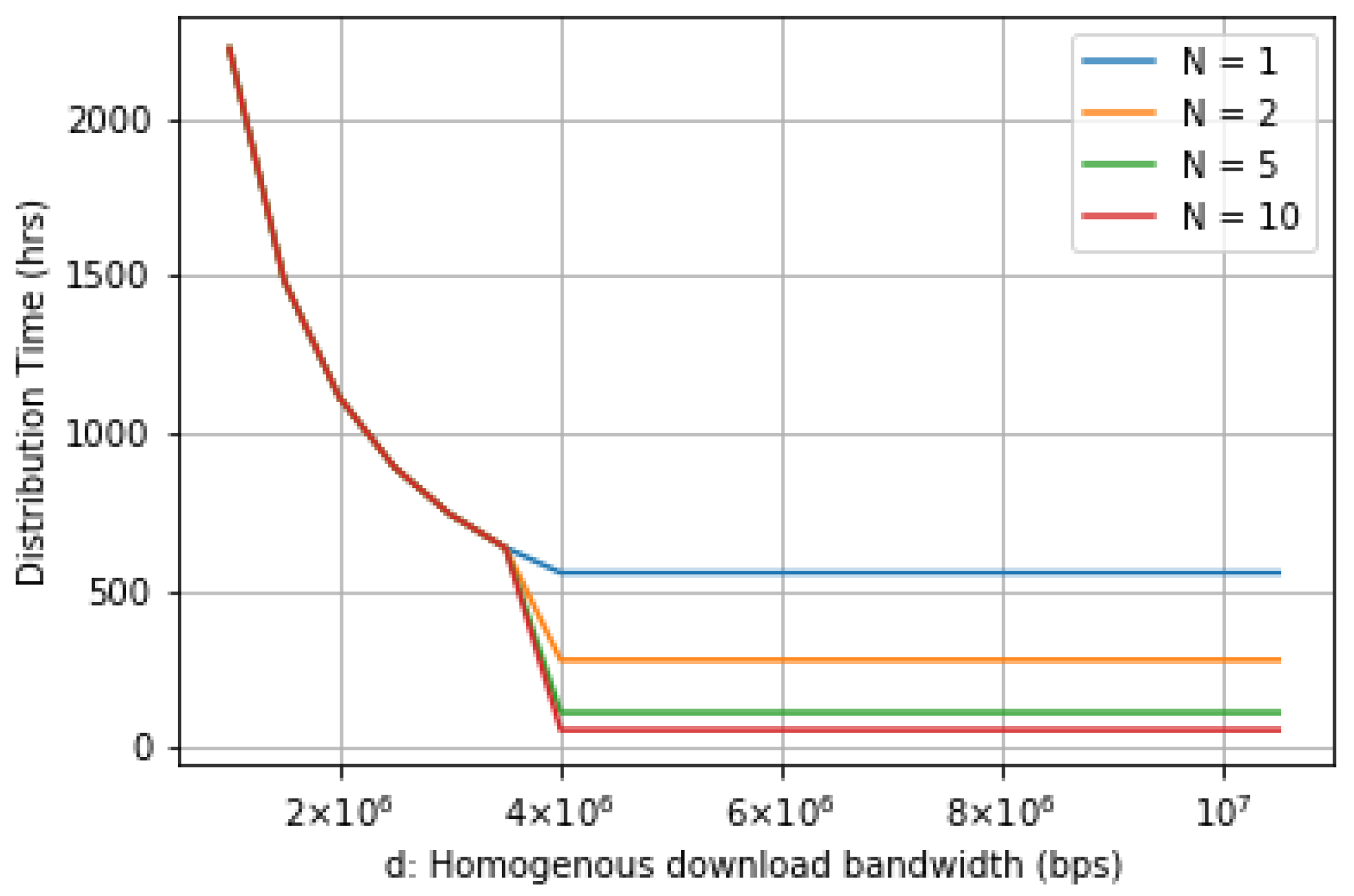
6.2. Distribution Time Evaluation
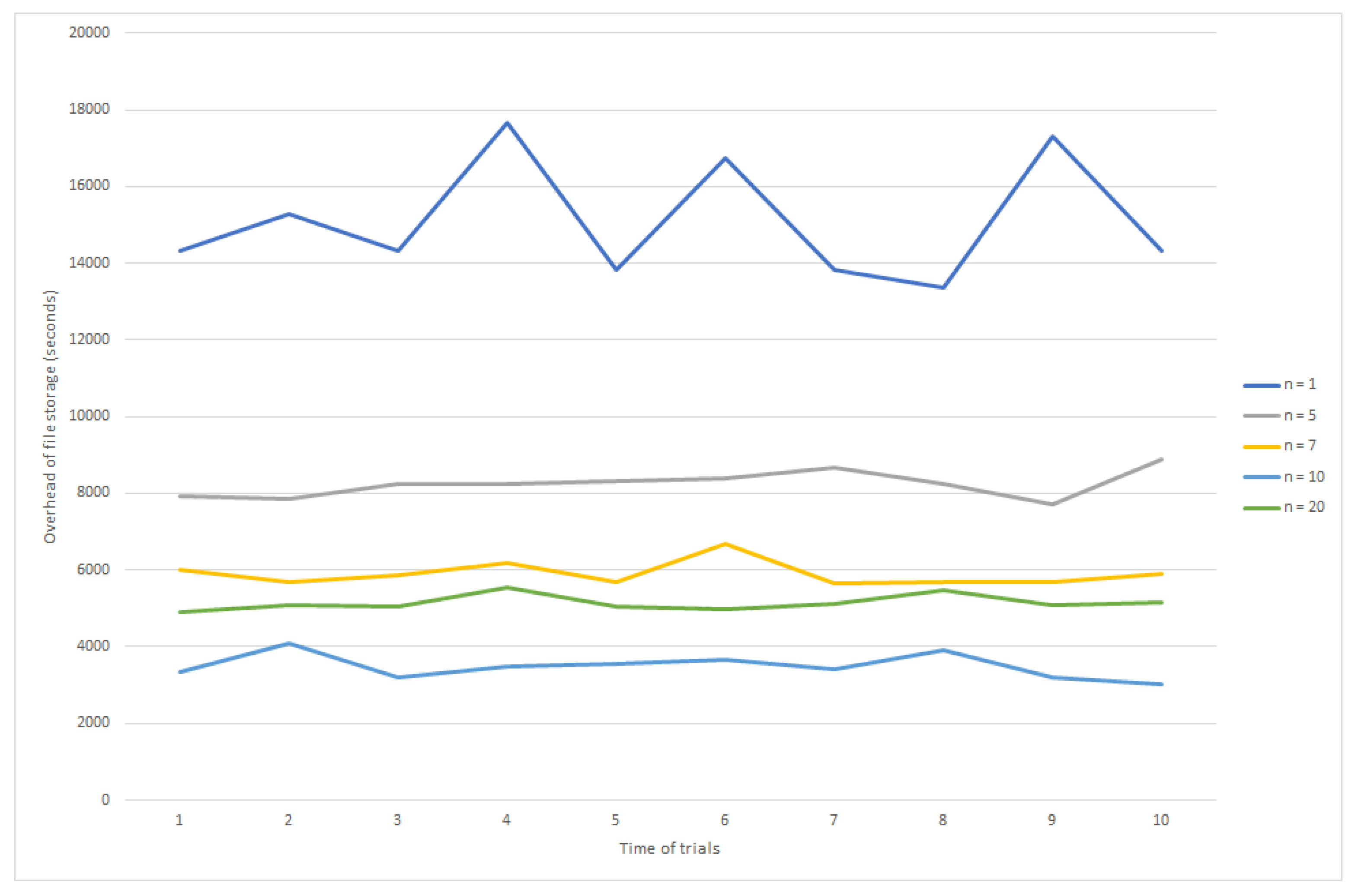
This section presents the distribution time evaluation of our system in different configurations by referring to Theorem 1. We assume that the download rate of the slowest client (leecher or downloader), d m i n , is higher than the aggregate upload bandwidth of a set of CSPs (seeders) is u ( S ) . The distribution time is then
T m i n = M F P u ( S )
We additionally approximate the aggregate upload bandwidth, u ( S ) , equal to the total upload speed of each CSP, v i :
u ( S ) = i = 1 N v i
In the case where each cloud has a static upload speed, the upload speeds of all CSPs are equal, which is v i = v . Thus,
u ( S ) = N v
Consequently, the distribution time is
T m i n = M F P N v
From [35], the minimum distribution time of the single CSP for sending its stored file to M user clients is
T m i n C S = F P min { d m i n , v 1 / M }
where v 1 is upload speed of single cloud storage provider, N = 1 . For the situation that d m i n is large and v 1 = v , the distribution time of single CSP is
T m i n C S = F P v / M = M F P v
We evaluated the factors that affect the distribution time characteristics. Figure 8 shows the effect of both the number of CSPs and the number of downloaders on the distribution time. In the multi-cloud storage scheme, all CSP upload speeds are equal to v = 100 Mbps. We calculated the distribution time to follow the configuration setup in Table 3.
Intuitively, the distribution time increases with the number of downloaders. When there are more downloaders, more copies of files need to be distributed to downloaders. On the other hand, the number of CSPs significant effect on the distribution time. When there are more CSPs, more upload capacity can be provided. This tends to decrease the distribution time. However, the distribution time is never close to zero, as it is limited by d m i n from Theorem 1.
We now study the effect of file size on the distribution time. It is shown in Figure 9 that, when the file size rises, the distribution time also progresses. However, the distribution time can be reduced if the download rate of downloaders is increased.
In this evaluation, the number of CSPs is ten, and the number of downloaders equals 100 users. The minimum download rate varies from 1 to 50 Mbps. However, we cannot increase the download rate to infinity in order to achieve zero downloading time. We discuss the rationale in the next evaluation.
To provide a clearer perception, we assess the influence of download bandwidth on distribution time. If the minimum download bandwidth is low, then it massively alters the value of distribution time. To explain this issue, we consider the download bandwidth when it is both less and greater than the aggregate upload bandwidth of the CSPs.
In Figure 10, the homogeneous download bandwidth d is varied along the x-axis. Similarly, the number of downloaders and plot the minimum distribution time is altered on the y-axis. The number of CSPs is fixed to one.
The single CSP provides its service to a various number of downloaders. We assume that each downloader has the equivalent download capability. When the value of d is lower than the aggregate upload of CSP, from Theorem 1, T m i n = F p d m i n . On the contrary, when d > u ( S ) , downloaders have the same minimum distribution time for all values of d. In addition, if the number of downloaders is increased, the minimum distribution time also increases.
In Figure 11, we further alter the homogeneous download bandwidth d, the number of CSPs, and plot the minimum distribution time on the y-axis. The number of the downloader is fixed to 1.
While the download bandwidth is less than the aggregate upload of CSPs, the distribution time is impacted by the download bandwidth. On the contrary, if the download bandwidth is higher than the aggregate upload of CSPs, the distribution time is constant along with all value of d. Additionally, when the number of CSPs is increased, the distribution time tends to decrease. The reason behind this situation is that the aggregate upload bandwidth is increased.

7. Simulation

We construct our proposed scheme on computer with Windows 10 operating system, Intel core i7-6700HQ CPU processor and 16G DDR memory to perform file spliting, mereging, encryption, and decryption. We separate a 10G big data into n ( n > 1 ) pieces of data. Our scheme connects to commercial cloud storage providers and private clouds. In general situation, the big data fil is always stored in single storage service provider, we call it as the traditional method. In simulation, we mainly evaluate the efficiency of the proposed scheme and the traditional one.
In simulation, the overhead of the traditional scheme includes the time of big data transmission from the client to cloud storage platforms. For the proposed scheme, the overhead includes the pre-processing cost of big data, which are file splitting, encryption, decryption, and the maximum transmission time of all the data parts. We test the proposed scheme in 5 different situations, which each situation handle different of number of fragments. In addition, we test each situation of the proposed scheme and the traditional Scheme 10 times individually. We record the whole process occur in our proposed scheme. It includes file splitting, fragments encryption, fragment uploading to cloud storage, fragment downloading from cloud storage, fragments decryption, and file merging. The simulation results are shown in Figure 12.
The simulation results in Figure 12 correspond to the analysis and evaluation in Section 5 and Section 6. From the simulation results, we can conclude that if we choose the suitable number of data fragments, the proposed scheme is more efficient than the traditional scheme. Even the communication cost reduce by parallel uploading/downloading, we can find that when the number of fragment exceeds a certain value, the proposed scheme will become less efficient. It needs more cost to process the big data. From the simulation results, it must have the balance between the overhead of data processing and data uploading/downloading. In real applications of the proposed scheme, the suitable data size depends on some factors such as data type, network performance, and client terminal’s computation capacity, which should be studied further.

8. Conclusions

An essential drawback of fog computing is low reliability, as the centralized network design implies having a single point of failure: the gateway device [38]. While fog computing expands the proximity of computing, it also increases the responsibility of maintenance and administration of fog nodes. The downtime of fog nodes malfunction or maintenance may generate a service pause, which may be serious in case of time-crucial situations [26].
Dew computing is a newly emerged paradigm. The primary purpose of this model is to make users feel they are still connected to cloud service even though they lost connection with the Internet. In this paper, we study the dew computing and introduce the idea of Storage In Dew (STiD). We proposed a framework for big data file sharing using a dew server as middleware. The dew server controls user access, and monitors the availability of file fragments on CSPs. The dew server seems to be a point of failure. However, the fault might occur anytime due to the nature of the dew server. As a result that it is a lightweight system, we can only install the dew server on new machines and roll back the saved configuration at the time before failure occurs. This paper analyzed security and fragment distribution time. We found that the probability that malicious users or adversaries can retrieve complete pieces and re-create the original file is extraordinary low. The distribution time can be decreased if we have an adequate number of CSP providers and a sufficient upload bandwidth. This paper also introduces the cloud selection method to achieve an optimal storage cost and download time.

Author Contributions

Conceptualization, P.S. and S.K.; methodology, P.S. and S.K.; software, P.S.; validation, S.K., S.H., and J.J.; formal analysis, P.S.; writing—original draft preparation, P.S.; writing—review and editing, S.K., S.H., and J.J.; supervision, S.K. All authors have read and agreed to the published version of the manuscript.

Funding

This research received no external funding.

Conflicts of Interest

The authors declare that there is no conflict of interest.

References

  1. Subashini, S.; Veeraruna, K. A survey on security issues in service delivery models of cloud computing. J. Netw. Comput. Appl. 2011, 34, 1–11. [Google Scholar] [CrossRef]
  2. Saurabh, S.; Young Sik, J.; Jong Hyuk, P. A survey on cloud computing security: Issues, threats, and solutions. J. Netw. Comput. Appl. 2016, 75, 200–222. [Google Scholar]
  3. Hui Shyong, Y.; Xiao Shen, P.; Hoon Jae, L.; Hyotaek, L. Leveraging client-side storage techniques for enhanced use of multiple consumer cloud storage services on resource-constrained mobile devices. J. Netw. Comput. Appl. 2016, 43, 142–156. [Google Scholar]
  4. Subramanian, K.; Leo, J. Enhanced Security for Data Sharing in Multi Cloud Storage (SDSMC). Int. J. Adv. Comput. Sci. Appl. 2017, 8, 176–185. [Google Scholar]
  5. Abu-Libdeh, H.; Princehouse, L.; Weatherspoon, H. RACS: A case for cloud storage diversity. In Proceedings of the 1st ACM Symposium on Cloud Computing (SoCC 10), Indianapolis, IN, USA, 6–11 June 2010; pp. 229–240. [Google Scholar]
  6. Wang, Y. Definition and Categorization of Dew computing. Open J. Cloud Comput. 2016, 3, 1–7. [Google Scholar]
  7. Security Guidelines for Critical Areas of Focus in Cloud Computing v3.0. Available online: https://cloudsecurityalliance.org/artifacts/security-guidance-or-critical-areas-of-focus-in-cloud-computing-v3/ (accessed on 19 May 2020).
  8. Chen, D.; Li, X.; Wang, L.; Khan, S.U.; Wang, J.; Zeng, K.; Cai, C. Fast and Scalable Multi-Way Analysis of Massive Neural Data. IEEE Trans. Comput. 2015, 64, 707–719. [Google Scholar] [CrossRef]
  9. Ali, M.; Dhamotharan, R.; Khan, E.; Khan, S.U.; Vasilakos, A.V.; Li, K.; Zomay, A.Y. SeDaSC: Secure Data Sharing in Clouds. IEEE Syst. J. 2017, 11, 395–404. [Google Scholar] [CrossRef]
  10. Plantard, T.; Susilo, W.; Zhang, Z. Fully Homomorphic Encryption Using Hidden Ideal Lattice. IEEE Trans. Inf. Forensics Secur. 2013, 8, 2127–2137. [Google Scholar] [CrossRef]
  11. Li, M.; Yu, S.; Zheng, Y.; Ren, K.; Lou, W. Scalable and Secure Sharing of Personal Health Records in Cloud Computing Using Attribute-Based Encryption. IEEE Trans Parallel Distrib. Syst. 2013, 24, 131–143. [Google Scholar] [CrossRef] [Green Version]
  12. Zhou, S.; Du, R.; Chen, J.; Deng, H.; Shen, J.; Zhang, H. SSEM: Secure, scalable and efficient multi-owner data sharing in clouds. China Commun. 2016, 13, 231–243. [Google Scholar] [CrossRef]
  13. Brakerski, Z.; Gentry, C.; Vaikuntanathan, V. (Leveled) fully homomorphic encryption without bootstrapping. ACM Trans. Comput. Theory 2014, 6, 1–36. [Google Scholar] [CrossRef]
  14. Bowers, K.D.; Juels, A.; Oprea, A. HAIL: A High-Availability and Integrity Layer for Cloud Storage. In Proceedings of the 16th ACM Conference on Computer and Communications Security (CCS 09), Chicago, IL, USA, 9–13 November 2009; pp. 187–198. [Google Scholar]
  15. Bessani, A.; Correia, M.; Quaresma, B.; André, F.; Sousa, P. DEPSKY: Dependable and Secure Storage in a Cloud-of-Clouds. ACM Trans. Storage 2013, 9, 1–33. [Google Scholar] [CrossRef]
  16. Su, M.; Zhang, L.; Wu, Y.; Chen, K.; Li, K. Systematic Data Placement Optimization in Multi-Cloud Storage for Complex Requirements. IEEE Trans. Comput. 2016, 65, 1964–1977. [Google Scholar] [CrossRef]
  17. Subramanian, K.; John, F.L. Dynamic and secure unstructured data sharing in multi-cloud storage using the hybrid crypto-system. Int. J. Adv. Appl. Sci. 2018, 5, 15–23. [Google Scholar] [CrossRef]
  18. Nehe, S.; Vaidya, M.B. Data security using data slicing over storage clouds. In Proceedings of the IEEE International Conference on Information Processing (ICIP 2015), Pune, Maharashtra, India, 16–19 December 2015; pp. 322–325. [Google Scholar]
  19. Bucur, V.; Dehelean, C.; Miclea, L. Object storage in the cloud and multi-cloud: State of the art and the research challenges. In Proceedings of the 2018 IEEE International Conference on Automation, Quality and Testing, Robotics (AQTR 2018), Cluj-Napoca, Romania, 24–26 May 2018; pp. 1–6. [Google Scholar]
  20. Sánchez, D.; Batet, M. Privacy-preserving data outsourcing in the cloud via semnatic data splitting. Comput. Commun. 2017, 110, 187–201. [Google Scholar] [CrossRef] [Green Version]
  21. The Initial Definition of Dew Computing. Available online: http://www.dewcomputing.org/index.php/2015/11/10/the-initial-definition-of-dew-computing/ (accessed on 12 January 2020).
  22. Ray, P.P. An Introduction to Dew Computing: Definition, Concept and Implication. IEEE Access 2017, 6, 723–737. [Google Scholar] [CrossRef]
  23. Longo, M.; Hirsch, M.; Mateos, C.; Zunino, A. Towards Integrating Mobile Devices into Dew Computing: A Model for Hour-Wise Prediction of Energy Availability. Information 2019, 10, 86. [Google Scholar] [CrossRef] [Green Version]
  24. Vaquero, L.M.; Rodero-Merino, L. Finding your way in the fog: Towards a comprehensive definition of fog computing. ACM SIGCOMM Comput. Commu. Rev. 2014, 44, 27–32. [Google Scholar] [CrossRef]
  25. Alessio, B.; Luigi, G.; Giorgio, V. Cloud, fog, and dew robotics: Architectures for next generation applications. In Proceedings of the 7th IEEE International Conference on Mobile Cloud Computing, Services, and Engineering (MobileCloud 2019), Newark, CA, USA, 4–9 April 2019; pp. 16–23. [Google Scholar]
  26. Tushar, M.; Himanshu, A. Cloud-fog-dew architecture for refined driving assistance: The complete service computing ecosystem. In Proceedings of the IEEE 17th International Conference on Ubiquitous Wireless Broadband (ICUWB 2017), Salamanca, Spain, 12–15 September 2017; pp. 1–7. [Google Scholar]
  27. Skala, K.; Davidovic, D.; Afgan, E.; Sovic, I.; Sojat, Z. Scalable Distributed Computing Hierarchy: Cloud, Fog and Dew Computing. Open J. Cloud Comput. 2015, 2, 16–24. [Google Scholar]
  28. Wang, Y. The Relationships among Cloud Computing, Fog Computing, and Dew Computing. Available online: http://www.dewcomputing.org/index.php/2015/11/12/the-relationships-among-cloud-computing-fog-computing-and-dew-computing/ (accessed on 19 May 2020).
  29. Wang, Y.; Pan, Y. Cloud-dew architecture: Realizing the potential of distributed database systems in unreliable networks. In Proceedings of the International Conference on Parallel and Distributed Processing Techniques and Applications, Athens, Greece, 27–30 July 2015; pp. 85–89. [Google Scholar]
  30. Guo, F.; Susilo, W.; Mu, Y. Distance-based encryption: How to embed fuzziness in biometric-based encryption. IEEE Trans. Inf. Forensics Secur. 2016, 11, 247–257. [Google Scholar] [CrossRef]
  31. Li, Y.; Gai, K.; Qiu, L.; Qiu, M.; Zhao, H. Intelligent cryptography approach for secure distributed big data storage in cloud computing. Inf. Sci. 2017, 387, 103–115. [Google Scholar] [CrossRef]
  32. Gai, K.; Qiu, M.; Zhao, H. Security-Aware Efficient Mass Distributed Storage Approach for Cloud Systems in Big Data. In Proceedings of the IEEE 2nd International Conference on Big Data Security on Cloud (BigDataSecurity), IEEE International Conference on High Performance and Smart Computing (HPSC), and IEEE International Conference on Intelligent Data and Security (IDS), New York, NY, USA, 9–10 April 2016; pp. 140–145. [Google Scholar]
  33. Edward, F.D.; Shuhui, Y. Doing More with the Dew: A New Approach to Cloud-Dew Architecture. Open J. Cloud Comput. 2016, 3, 8–19. [Google Scholar]
  34. Hongbing, C.; Chunming, R.; Kai, H.; Weihong, W.; Yanyan, L. Secure big data storage and sharing scheme for cloud tenants. China Commun. 2015, 12, 106–115. [Google Scholar]
  35. Suwansrikham, P.; She, K. Asymmetric Secure Storage Scheme for Big Data on Multiple Cloud Providers. In Proceedings of the 4th IEEE International Conference on Big Data Security on Cloud (BigDataSecurity 2018), Omaha, NE, USA, 3–5 May 2018; pp. 121–125. [Google Scholar]
  36. Kumar, R.; Ross, K. Peer-Assisted File Distribution: The Minimum Distribution Time. In Proceedings of the 1st IEEE Workshop on Hot Topics in Web Systems and Technologies, Boston, MA, USA, 13–14 November 2006; pp. 1–11. [Google Scholar]
  37. Meng, X.; Tsang, P.S.; Lui, K. Analysis of distribution time of multiple files in a P2P network. Comput. Netw. 2013, 57, 2900–2915. [Google Scholar] [CrossRef]
  38. Cristescu, G.; Dobrescu, R.; Chenaru, O.; Florea, G. Dew: A new edge computing component for distributed dynamic networks. In Proceedings of the 22nd International Conference on Control Systems and Computer Science (CSCS 2019), Bucharest, Romania, 28–30 May 2019; pp. 547–551. [Google Scholar]
Figure 1. Dew computing structure.
Information 11 00303 g001
Figure 2. Cloud-dew architecture [29].
Information 11 00303 g002
Figure 3. The proposed architecture of dew computing and asymmetric security framework for big data file sharing.
Information 11 00303 g003
Figure 4. Dew server structure.
Information 11 00303 g004
Figure 5. Details of file fragment distribution.
Information 11 00303 g005
Figure 6. Probability that an attacker retrieves all fragments when the storage path is known.
Information 11 00303 g006
Figure 7. Probability that attaker retrive all fragments in condition storage path is unknown.
Information 11 00303 g007
Figure 8. Distribution time when F P = 1 TB, v = 100 Mbps.
Information 11 00303 g008
Figure 9. Distribution time when N = 10, M = 100.
Information 11 00303 g009
Figure 10. Distribution time while d is varied for some value of M.
Information 11 00303 g010
Figure 11. Distribution time while d is varied for some value of N.
Information 11 00303 g011
Figure 12. Overhead of two schemes to deal with big data storage.
Information 11 00303 g012
Table 1. Comparative analysis between fog and dew computing.
Computing ModelOriginFeaturesApplications
FogVice president of Cisco, in 2011Extends cloud computing to the edge of networkLatency-sensitive applications, large-scale distributed control systems, and geo-distributed applications
DewWang in 2015Improve scalability [25]Offline or local area computation [26]
Table 2. Basic detail of the metadata.
Entity NameDetails
UsernameFor logging in to each cloud storage provider
PasswordAuthority code that corresponds to the username of a cloud storage provider
DirectoryLocation of each cloud that keeps file fragments
Integrity ValueIntegrity value of each file fragment, e.g., MD5
Table 3. Configuration for distribution time calculation.
ConfigurationNo. of CSPs ( N )
Single CSP1
Configuration 15
Configuration 210
Configuration 315
Configuration 420

