Abstract
The accurate analysis of periodic surface acoustic wave (SAW) structures by combined finite element method and boundary element method (FEM/BEM) is important for SAW design, especially in the extraction of couple-of-mode (COM) parameters. However, the time cost is very large. With the aim to accelerate the calculation of SAW FEM/BEM analysis, some optimization algorithms for the FEM and BEM calculation have been reported, while the optimization for the solution to the final FEM/BEM equations which is also with a large amount of calculation is hardly reported. In this paper, it was observed that the coefficient matrix of the final FEM/BEM equations for the periodic SAW structures was similar to a Toeplitz matrix. A fast algorithm based on the Trench recursive algorithm for the Toeplitz matrix inversion was proposed to speed up the solution of the final FEM/BEM equations. The result showed that both the time and memory cost of FEM/BEM was reduced furtherly.
1. Introduction
The surface acoustic wave (SAW) devices are playing more and more of an important role in RF communication and MEMS sensors. Thus, the simulation methods for SAW structures are theoretical bases for the SAW device fabrication. The simulation methods are divided into two categories: physical approximated models and rigorous models. The physical approximated models include the delta function model [1], impulse model [1,2], equivalent circuit model [3,4], and coupling-of-modes (COM) [5,6,7,8]. These phenomenological models are fast, but the accuracy is poor or the model parameters have to be obtained by some other methods, such as COM parameters [9,10,11]. The rigorous models include the finite element model (FEM), the boundary element model (BEM) [12,13,14,15], and, the combined FEM and BEM (FEM/BEM) [16]. The finite FEM/BEM [17,18,19,20] can combine the advantages of the two methods and simulate the infinite SAW structure accurately. However, the time cost of the FEM/BEM is very large.
To accelerate the accurate SAW device simulation, some optimization algorithms for the FEM and BEM calculation have been reported. Laude et al. introduced asymptotic waveform evaluation (AWE) to reduce the FEM computation for periodic SAW structures [21]. Ke et al. approximated the equations’ coefficients by poles to simplify the solution of the equations [22]. Ventura et al. reduced the dimension of algebraic equations by using the Chebyshev polynomial to approximate Green’s function [20]. Wang, Luo, and Ke et al. did more optimization in BEM based on Ventura’s research [21,23,24]. Peach approximated Green’s function by exponential terms to reduce the time cost in BEM [19]. In addition, some researchers used finite FEM/BEM to extract accurate COM parameters and simulated the SAW devices by the COM method [25]. Thus, the finite FEM/BEM based on periodic SAW devices is one of the most important methods for the extraction of COM parameters. The speed of the simulation was improved, and the computational accuracy could be also ensured.
These studies above were aimed at FEM and BEM, while the time cost of the solution to the final FEM/BEM equations is also very large. Based on the methods above, most of the FEM/BEM computation is transferred to the final solution, which has a large proportion above 80% in the total calculation. Additionally, the optimization of solving the final FEM/BEM equations is hardly reported. It was observed that the coefficient matrix of the final FEM/BEM equations for the periodic SAW structures was similar to a Toeplitz matrix,
Trench proposed a recursive inversion algorithm for the Toeplitz matrix [26,27,28]. It reduced the process of matrix inversion to order N2 instead of N3 [28]. Based on the algorithm of Trench and Bereux [29], a fast algorithm is proposed to inverse the coefficient matrix of the final FEM/BEM equations. Thus, the solution to the final FEM/BEM equations could be accelerated.
In this paper, firstly, the final equations of the FEM/BEM for the periodic SAW structures are introduced. Additionally, the coefficient matrix inversion algorithm based on the Trench recursive algorithm is carried out to accelerate the solution to the final FEM/BEM equations. Then, the accuracy and speed by comparing with the conventional matrix inversion algorithm are verified. Lastly, the computational experiments based on a one port Al/36°YXLiTaO3 SAW resonator were conducted. The result shows that both the time and memory cost of FEM/BEM was further reduced without changing the accuracy of the calculation.
2. Theory
The aim of this chapter is to give the final FEM/BEM equations for the periodic SAW structures and propose a fast algorithm for the coefficient matrix inversion based on the Trench recursive algorithm.
2.1. The Final FEM/BEM Equations for the Periodic SAW Structures
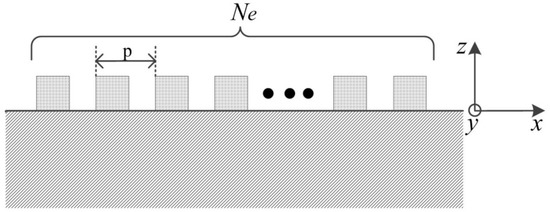
In the FEM/BEM theory, the model of SAW devices is shown in Figure 1, in which the piezoelectric substrate can be assumed to be a semi-infinite solid occupying the region z < 0. The surface of the structure is loaded with metal strip gratings. The grating electrodes are parallel to the y-axis and are assumed to be long enough along the y-axis such that any dependence on y can be ignored. The FEM/BEM for SAW structures can be divided into two parts: FEM and BEM.

Figure 1.
The schematic drawing of the periodic surface acoustic wave (SAW) structures.
According to the theory of FEM/BEM [16,20,22], the final equations of BEM is
where,, are displacement coefficients and potential coefficients, respectively [20]. Displacement has three values. Potential has one value. , are the approximation coefficients of stress and charge density, respectively. is the Chebyshev polynomial expansion coefficient [16,20,22]. is the number of the interdigital transducer (IDT) fingers. The equations coefficient matrix is an integral about Green’s function.
The final equation of FEM is
where, is the equations coefficient matrix.
Based on charge conservation principle,
by assuming the supply voltage is 1 V, the potential coefficients of electrodes are [20,30].
We define that,
where, is the electrode on the positive pole of the power supply, and is a potential of Reference [30].
According to Equations (2)–(6), we can get the final FEM/BEM equations,
Suppose that the coefficient matrix of Equation (8) is partitioned into
where, is a constant vector and can be written as
where,
where,
is a matrix. For periodic SAW structures, we have
Let , for . So Equation (9) can be written as
where, , . is a block Toeplitz matrix. Different from Equation (1), every element of is a matrix. The coefficient matrix is just one more row and column than a block Toeplitz matrix. Thus, a fast algorithm is carried out based on the Trench inversion algorithm for the Toeplitz matrix to speed up the solution of Equation (7).
2.2. Fast Inversion Algorithm
First, find the relationship between and , which are assumed to be the inversions of and , respectively. can be partitioned into
where, is a matrix. is vector. is vector. So we have
That is
Moreover,
With Equations (17) and (18), we get the solution of , , , in Equations (15) and the relationship between and ,
where,
Next, we calculate the inversion of based on the Trench recursive algorithm. According to Equation (14), is like
We assume the inversion of and is and , respectively, and partition into
By using the same method of getting the relationship between of and , we get a relationship between and ,
where, is a matrix,
can also be partitioned into
Similarly, we get another relationship between and ,
where, is a matrix,
Define that
Since ,
Trench used the sub-symmetric property of a Toeplitz matrix in his algorithm to reduce the number of defined parameter sets from four to two, in Equations (28)–(31). However, is not a sub-symmetric matrix in this paper. However, we can use the transposition property to keep the new algorithm with the same complexity as Trench’s algorithm.
By expanding Equations (23) and (26), the elements of are
By removing from Equations (33) and (34), we get
where,
Let , for , and bring it to Equations (32) and (35) to obtain the iterative relationships for calculating the elements of ,
This implies that if and for have been calculated, we can get . Thus, the key for calculating is to calculate
According to Equation (26) and the definitions of and , we have
where,
Summarizing the procedure of inversing :
The initial value:
Step 1: take from 0 to , for , and calculate Equations (42)–(45) to get , , and , for .
Step 2: according to Equations (38) and (39), calculate every element of .
Thus, can be calculated by bringing to Equation (19).
Finally, we get the solution of the final FEM/BEM equation for periodic SAW structures. Since the new fast algorithm is one lower order than the normal inversion algorithm, we can reduce the complexity of the FEM/BEM simulation.
3. Algorithm Verification
Several groups of computational examples based on the one port Al/42°YXLiTaO3 SAW resonator were conducted to exemplify the new fast optimization algorithm by Matlab. The accuracy of this algorithm is verified by comparing it with the traditional method per frequency point, and the time cost and memory cost at one frequency point were calculated with different numbers of electrodes, which was from 300 to 1800.
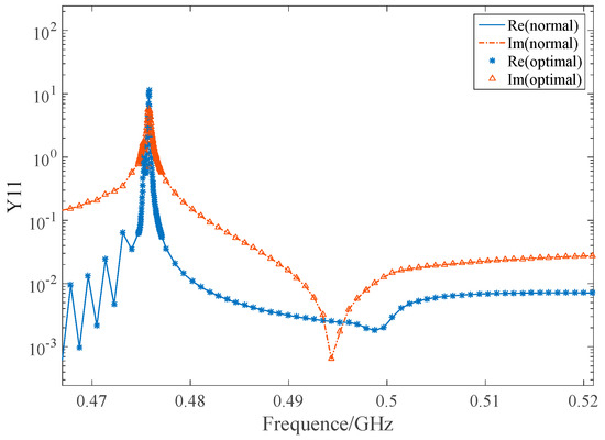
Since this algorithm used the recursion method to accelerate the inversion of the coefficient matrix of the final FEM/BEM equations without any estimate, the accuracy of the solution was not affected. In Figure 2, the two lines represent the real and imaginary parts of Y11 calculated by normal FEM/BEM, respectively. The device parameters are as follows: the substrate of the sample is 42°YXLiTaO3. The electrode is aluminium. The number of electrodes is 400. Only one set of IDT is simulated here and the period of the IDT is 4.0 µm. The metallization ratio of the IDT is 0.5 and the film thickness is 0.88 µm. The aperture of the IDT is 200 µm. The two kinds of markers represent the real and imaginary parts respectively of Y11 calculated by optimal FEM/BEM. The two kinds of the algorithm had almost the same accuracy.

Figure 2.
The Y11 calculated by (finite element method and boundary element method) FEM/BEM for periodic SAW structures with 200 electrodes.
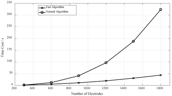
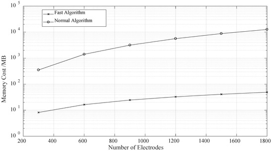
The time cost of the FEM/BEM for Periodic SAW Structures was reduced significantly with the rising number of electrodes, as shown in Figure 3. With 1800 electrodes, the time cost of the fast algorithm had a decrease of above 86%. The new fast algorithm was one lower order than the normal algorithm. At the same time, the memory cost was also reduced obviously, as shown in Figure 4.

Figure 3.
The time cost of the FEM/BEM for periodic SAW structures.

Figure 4.
The memory cost of the FEM/BEM for periodic SAW structures.
4. Conclusions
FEM/BEM method is essential for the rigorous simulation for periodic SAW structures, but with a large amount of calculation. Different from other reported speed optimization methods, this new fast algorithm was focused on the solution of the FEM/BEM final equations, of which the calculation had a large proportion in the SAW FEM/BEM simulation. For periodic SAW structures, the coefficient matrix of the final FEM/BEM equations is similar to a Toeplitz matrix. By proposing a recursive algorithm for the inversion of the coefficient matrix based on the Trench inversion algorithm for Toeplitz matrixes, the algorithm complexity can be reduced significantly with the same accuracy.
The computational results confirmed that the new fast algorithm had one lower order than the normal algorithm. Additionally, the new optimization algorithm has great advantages in both the time and memory costs with a large number of electrodes.
Author Contributions
Conceptualization, H.L. and Z.L.; Formal analysis, Y.K. and Z.L.; Funding acquisition, H.L. and W.L.; Methodology, H.L. and Z.L.; Resources, Y.K. and W.L.; Software, Y.K. and Z.L.; Supervision, H.L.; Validation, Y.K. and Z.L.; Writing—original draft, Z.L.; Writing—review & editing, Y.K. and W.L.
Funding
This work was supported by the National Key Research and Development Program (Grant No. 2016YFB0402705), the Key Program of Chinese Academy of Sciences (Grant No. KFZD-SW-415), the National Natural Science Foundation of China (Grant No. 11574106 and 11874169), and the Fundamental Research Projects of Shenzhen City (Grant No. JCYJ20150831202835225).
Conflicts of Interest
The authors declare no conflict of interest.
References
- Tancrell, R.H.; Holland, M.G. Acoustic Surface Wave Filters. In Proceedings of the IEEE 1970 Ultrasonics Symposium, San Francisco, CA, USA, 21–23 October 1970; pp. 393–409. [Google Scholar]
- Hartmann, C.S.; Bell, D.T.; Rosenfeld, R.C. Impulse model design of acoustic surface-wave filters. IEEE Tran. Microw. Theory Tech. 1973, 21, 162–175. [Google Scholar] [CrossRef]
- Smith, W.R.; Gerard, H.M.; Collins, J.H.; Reeder, T.M.; Shaw, H.J. Analysis of interdigital surface wave transducers by use of an equivalent circuit model. IEEE Trans. Microw. Theory Tech. 1969, 17, 856–864. [Google Scholar] [CrossRef]
- Smith, W.R. Experimental distinction between crossed-field and in-line three-port circuit models for interdigital transducers (short papers). IEEE Trans. Microw. Theory Tech. 1974, 22, 960–964. [Google Scholar] [CrossRef]
- Hartmann, C.S.; Wright, P.V.; Kansy, R.J.; Garber, E.M. An analysis of saw interdigital transducers with internal reflections and the application to the design of single-phase unidirectional transducers. In Proceedings of the IEEE Ultrasonics Symposium, San Diego, CA, USA, 27–29 October 1982; pp. 40–45. [Google Scholar]
- Dong-Pei, C.; Haus, H.A. Analysis of metal-strip saw gratings and transducers. IEEE Trans. Sonics Ultrason. 1985, 32, 395–408. [Google Scholar] [CrossRef]
- Plessky, V.P. A two parameter coupling-of-modes model for shear horizontal type saw propagation in periodic gratings. In Proceedings of the IEEE Ultrasonics Symposium, Baltimore, MD, USA, 31 October–3 November 1993; Volume 191, pp. 195–200. [Google Scholar]
- Abbott, B.P.; Hashimoto, K. A coupling-of-modes formalism for surface transverse wave devices. In Proceedings of the 1995 IEEE Ultrasonics Symposium, Seattle, WA, USA, 7–10 November 1995; Volume 231, pp. 239–245. [Google Scholar]
- Koskela, J.; Plessky, V.P.; Salomaa, M.M. Saw/lsaw com parameter extraction from computer experiments with harmonic admittance of a periodic array of electrodes. IEEE Trans. Ultrason. Ferroelectr. Freq. Control 1999, 46, 806–816. [Google Scholar] [CrossRef] [PubMed]
- Plessky, V.; Koskela, J. Coupling-of-modes analysis of saw devices. Int. J. High Speed Electr. Syst. 2000, 10, 867–947. [Google Scholar] [CrossRef]
- Plessky, V.P.; Chen, D.P.; Hartmann, C.S. “Patch” improvements to com model for leaky waves. In Proceedings of the IEEE Ultrasonics Symposium, Cannes, France, 31 October–3 November 1994; Volume 291, pp. 297–300. [Google Scholar]
- Buchner, M.; Ruile, W.; Dietz, A.; Dill, R. Fem analysis of the reflection coefficient of saws in an infinite periodic array. In Proceedings of the 1991 IEEE Ultrasonics Symposium, Orlando, FL, USA, 8–11 December 1991; Volume 371, pp. 371–375. [Google Scholar]
- Milsom, R.F.; Reilly, N.H.C.; Redwood, M. Analysis of generation and detection of surface and bulk acoustic waves by interdigital transducers. IEEE Trans. Sonics Ultrason. 1977, 24, 147–166. [Google Scholar] [CrossRef]
- Baghai-Wadji, A.R.; Manner, O.; Ganss-Puchstein, R. Analysis and measurement of transducer end radiation in saw filters on strongly coupling substrates. IEEE Trans. Microw. Theory Tech. 1989, 37, 150–158. [Google Scholar] [CrossRef]
- Visintini, G.; Baghai-Wadji, A.; Manner, O. Modular two-dimensional analysis of saw filters. I. Theory. IEEE Trans. Ultrason. Ferroelectr. Freq. Control 1992, 39, 61–72. [Google Scholar] [CrossRef] [PubMed]
- Ventura, P.; Hode, J.M.; Solal, M.; Desbois, J.; Ribbe, J. Numerical methods for saw propagation characterization. In Proceedings of the 1998 IEEE Ultrasonics Symposium, Sendai, Japan, 5–8 October 1998; Volume 171, pp. 175–186. [Google Scholar]
- Finger, N.; Kovacs, G.; Schoberl, J.; Langer, U. Accurate fem/bem-simulation of surface acoustic wave filters. In Proceedings of the IEEE Symposium on Ultrasonics, Honolulu, HI, USA, 5–8 October 2003; Volume 1682, pp. 1680–1685. [Google Scholar]
- Peach, R.C. In 6d-3 simplified green function techniques for general saw device analysis and optimization. In Proceedings of the 2006 IEEE Ultrasonics Symposium, Vancouver, BC, Canada, 2–6 October 2006; pp. 371–375. [Google Scholar]
- Peach, R.C. Approximate green’s function representations for the analysis of saw and leaky wave devices. IEEE Trans. Ultrason. Ferroelectr. Freq. Control 2009, 56, 2268–2281. [Google Scholar] [CrossRef] [PubMed]
- Ventura, P.; Hode, J.M.; Lopes, B. Rigorous Analysis of Finite Saw Devices with Arbitrary Electrode Geometries. In Proceedings of the 1995 IEEE Ultrasonics Symposium Proceedings: An International Symposium, Seattle, WA, USA, 7–10 November 1995; Volume 251, pp. 257–262. [Google Scholar]
- Laude, V.; Reinhardt, A.; Wilm, M.; Khelif, A.; Ballandras, S. Fast FEM/BEM simulation of saw devices via asymptotic waveform evaluation. IEEE Trans. Ultrason. Ferroelectr. Freq. Control 2004, 51, 359–363. [Google Scholar] [CrossRef]
- Ke, Y.; Li, H.; He, S. Fast FEM/BEM simulation of non-periodic saw structures. In Proceedings of the 2012 IEEE International Ultrasonics Symposium, Dresden, Germany, 7–10 October 2012; pp. 815–818. [Google Scholar]
- Wang, W.B. Rigorous Simulation of Finite Length SAW Device. Ph.D. Thesis, Nanjing University, Nanjing, China, 2004. [Google Scholar]
- Luo, W. Simulation and Design of Wireless Passive Impedance-loaded SAW Sensors Based on the FEM/BEM Method. Ph.D. Thesis, Huazhong University of Science and Technology, Wuhan, China, 2009. [Google Scholar]
- Wang, H. Study on the Rapid and Precise Simulation of Surface Acoustic Wave Devices. Ph.D. Thesis, Nanjing University, Nanjing, China, 2013. [Google Scholar]
- Trench, W.F. An algorithm for the inversion of finite hankel matrices. J. Soc. Ind. Appl. Math. 1965, 13, 1102–1107. [Google Scholar] [CrossRef]
- Zohar, S. Toeplitz matrix inversion: The algorithm of W. F. Trench. J. ACM 1969, 16, 592–601. [Google Scholar] [CrossRef]
- Xu, S.L. Numerical Analysis and Algorithm; China Machine Press: Beijing, China, 2003; p. 76. (In Chinese) [Google Scholar]
- Béreux, N. Fast direct solvers for some complex symmetric block toeplitz linear systems. Linear Algebra Appl. 2005, 404, 193–222. [Google Scholar] [CrossRef]
- Gamble, K.J.; Malocha, D.C. Simulation of short LSAW transducers including electrode mass loading and finite finger resistance. IEEE Trans. Ultrason. Ferroelectr. Freq. Control 2002, 49, 47–56. [Google Scholar] [CrossRef]
© 2019 by the authors. Licensee MDPI, Basel, Switzerland. This article is an open access article distributed under the terms and conditions of the Creative Commons Attribution (CC BY) license (http://creativecommons.org/licenses/by/4.0/).