Design and Comparative Study of Advanced Adaptive Control Schemes for Position Control of Electronic Throttle Valve


Abstract
:1. Introduction
- To robustly control the position of the throttle plate of the throttle valve using adaptive backstepping control and adaptive sliding mode backstepping control.
- To robustly control the position of the throttle plate of the throttle valve.
- To cope the unknown (upper bounded) exerted disturbance based on adaptive backstepping control, where disturbance upper bound is needed.
- To cope the unknown upper bound of exerted disturbance using adaptive sliding mode backstepping control, where disturbance upper bound is estimated.
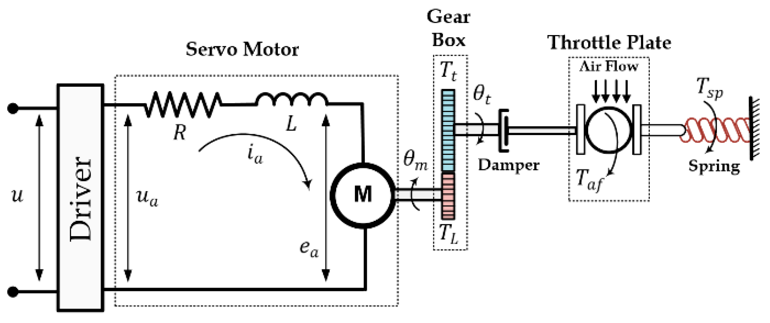
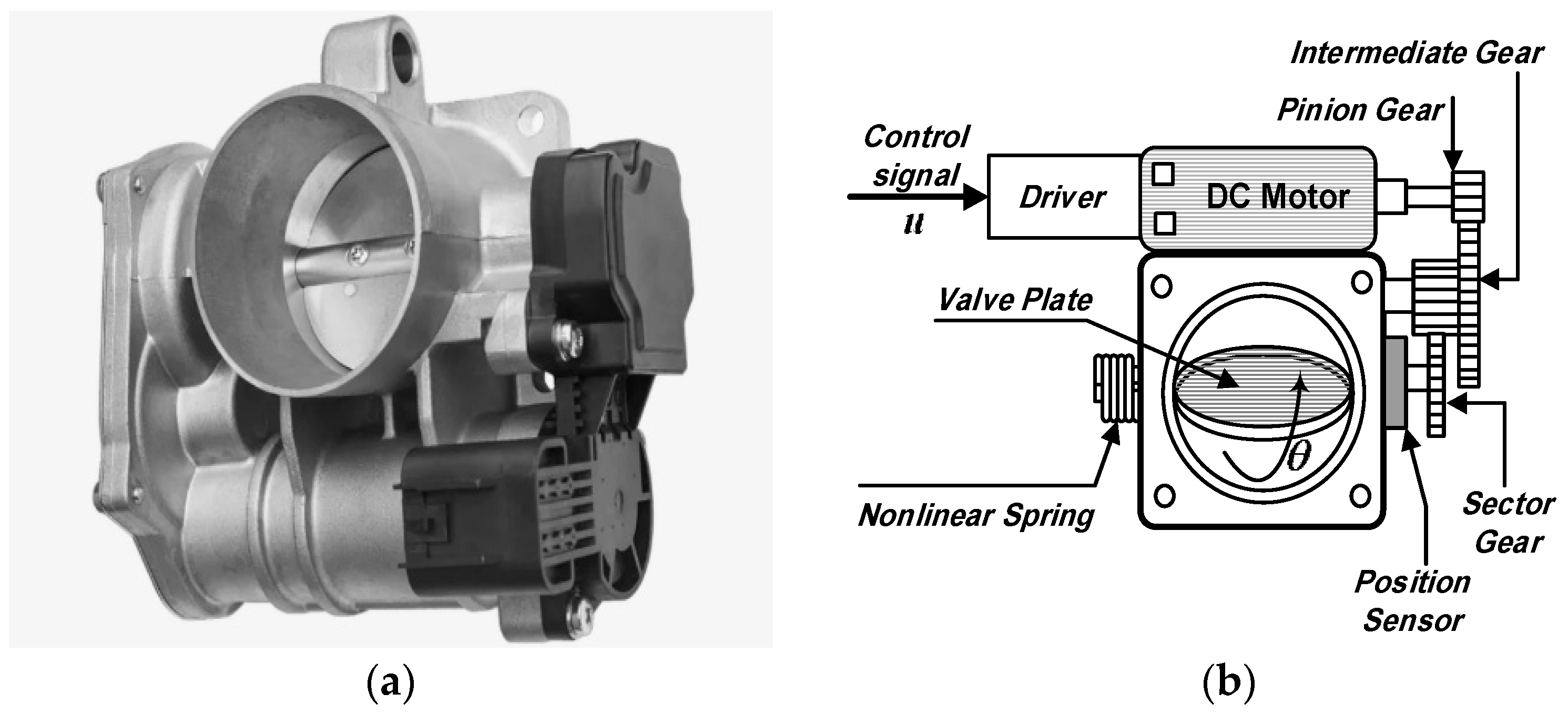
2. Mathematical Model
3. Controller Design and Stability Analysis
3.1. Backstepping Control
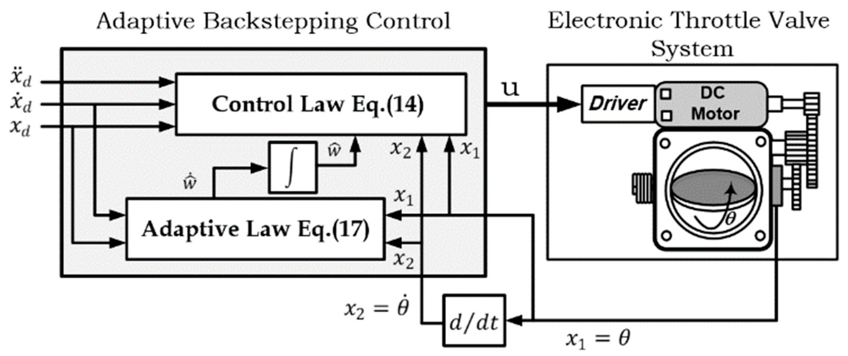
3.2. Adaptive Backstepping Control
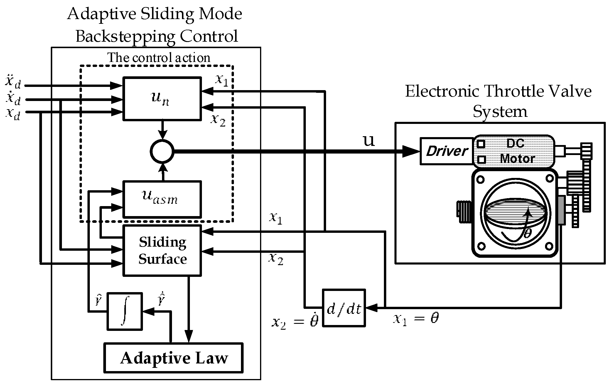
3.3. Adaptive Sliding Mode Backstepping Control
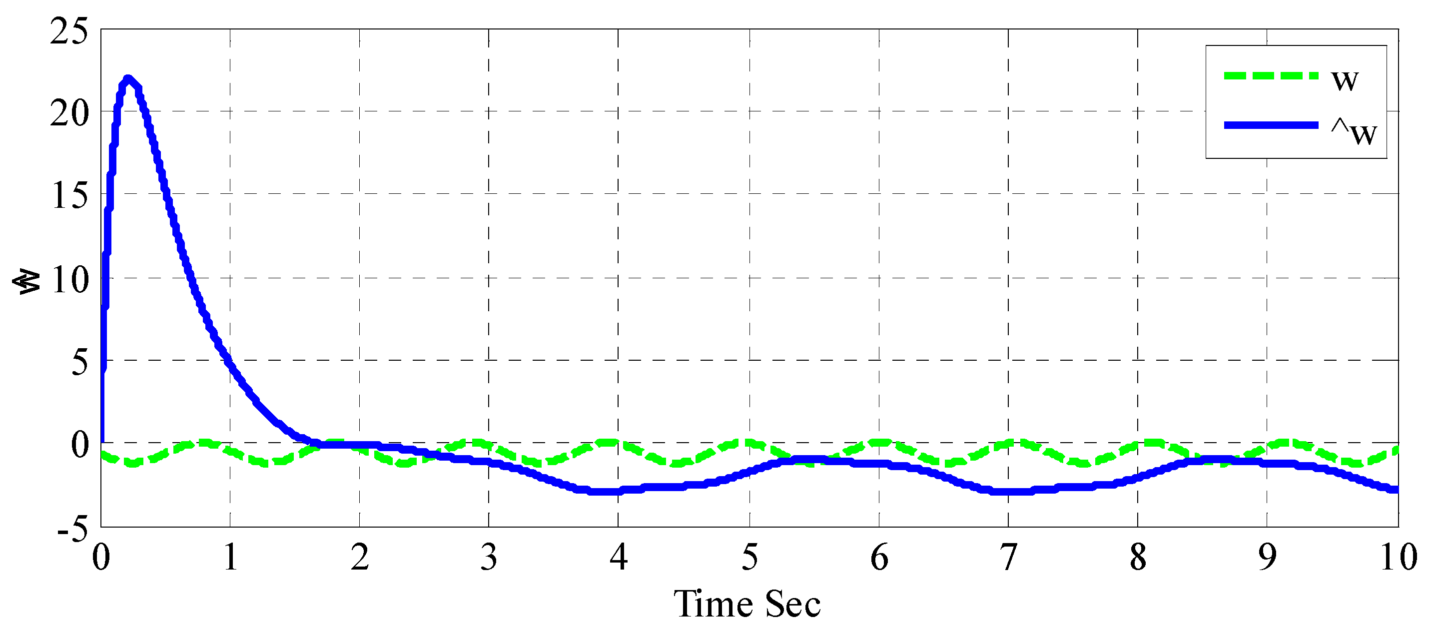
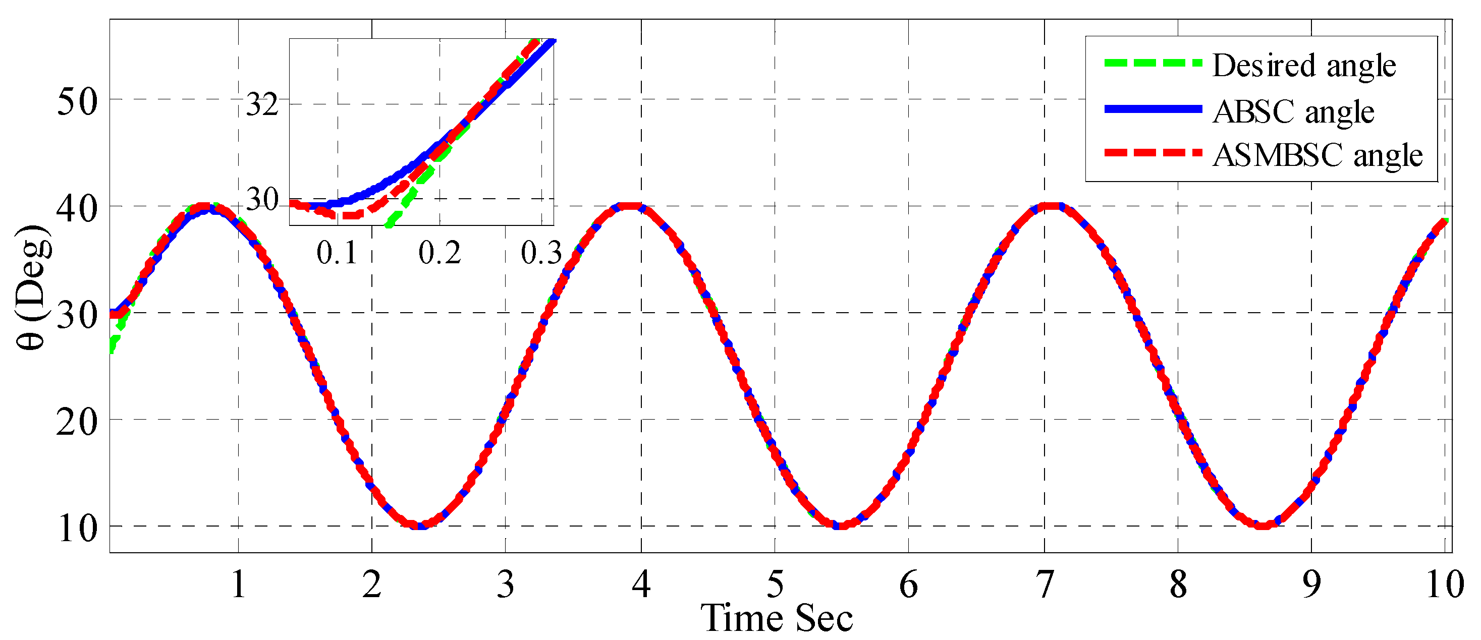
4. Computer Simulation
5. Conclusions
Author Contributions
Funding
Conflicts of Interest
References
- Loh, R.N.K.; Thanom, W.; Pyko, J.S.; Lee, A. Electronic Throttle Control System: Modeling, Identification and Model-Based Control Designs. Engineering 2013, 5, 587–600. [Google Scholar] [CrossRef]
- Schwartz, J.S. Design of an Automobile Accelerator/Brake Pedal Robot for Advanced Driver Assistance Systems. Ph.D. Thesis, Purdue University, West Lafayette, IN, USA, June 2017. [Google Scholar]
- Yadav, A.K.; Gaur, P.; Tripathi, S. Design and Control of an Intelligent Electronic Throttle Control System. In Proceedings of the IEEE International Conference on Energy Economics and Environment (ICEEE), Noida, India, 27–28 March 2015. [Google Scholar]
- Jiang, S.; Smith, M.H.; Kitchen, J. Optimization of PID Control for Engine Electronic Throttle System Using Iterative Feedback Tuning. SAE Technical Paper 2009. [Google Scholar] [CrossRef]
- Khalil, H.K. Nonlinear Systems; Prentice Hall: Upper Saddle River, NJ, USA, 2002. [Google Scholar]
- Krstic, M.; Kanellakopoulos, I.; Kokotovic, P.V. Nonlinear and Adaptive Control Design; Wiley: New York, NY, USA, 1995; Volume 222. [Google Scholar]
- Utkin, V.; Guldner, J.; Shi, J. Sliding Mode Control in Electro-Mechanical Systems; CRC Press: Boca Raton, FL, USA, 2009. [Google Scholar]
- Liu, J.; Wang, X. Advanced Sliding Mode Control for Mechanical Systems: Design, Analysis and MATLAB Simulation; Springer Science & Business Media: Berlin, Germany, 2012. [Google Scholar]
- Humaidi, A.J.; Hameed, A.H. PMLSM position control based on continuous projection adaptive sliding mode controller. Syst. Sci. Control Eng. 2018, 6, 242–252. [Google Scholar] [CrossRef]
- Humaidi, A.J.; Hameed, A.H. Robust MRAC for a Wing Rock Phenomenon in Delta Wing Aircrafts. Amirkabir Int. J. Model. Identif. Simul. Control 2017, 49, 113–122. [Google Scholar]
- Humaidi, A.J.; Hameed, A.H.; Hameed, M. Robust Adaptive Speed Control for DC Motor using Novel Weighted e-modified MRAC. In Proceedings of the IEEE International Conference on Power, Control, Signals and Instrumentation Engineering (ICPCSI-2017), Chennai, India, 21–22 September 2017. [Google Scholar]
- Chen, R.; Mi, L.; Tan, W. Adaptive fuzzy logic based sliding mode control of electronic throttle. J. Comput. Inf. Syst. 2012, 8, 3253–3260. [Google Scholar]
- Caruntu, C.; Vargas, A.; Acho Zuppa, L.; Pujol Vázquez, G. Adaptive-smith predictor for controlling an automotive electronic throttle over network. Int. J. Comput. Commun. Control 2018, 13, 151–161. [Google Scholar]
- Liu, X.; Vargas, A.N.; Yu, X.; Xu, L. Stabilizing two-dimensional stochastic systems through sliding mode control. J. Frankl. Inst. 2017, 354, 5813–5824. [Google Scholar] [CrossRef]
- Kurihara, N.; Yamaguchi, H. Adaptive Back-Stepping Control of Automotive Electronic Control Throttle. J. Softw. Eng. Appl. 2017, 10, 41. [Google Scholar] [CrossRef]
- Jiao, X.; Li, G.; Wang, H. Adaptive finite time servo control for automotive electronic throttle with experimental analysis. Mechatronics 2018, 53, 192–201. [Google Scholar] [CrossRef]
- Rui, B.; Yang, Y.; Wei, W. Nonlinear Backstepping Tracking Control for a Vehicular Electronic Throttle With Input Saturation and External Disturbance. IEEE Access 2018, 6, 10878–10885. [Google Scholar] [CrossRef]
- Nia, A.Z.; Nagamune, R. Switching Gain-Scheduled Proportional–Integral–Derivative Electronic Throttle Control for Automotive Engines. J. Dyn. Sys. Meas. Control 2018, 140, 071015. [Google Scholar]
- Yang, B.; Liu, M.; Kim, H.; Cui, X. Luenberger-sliding mode observer based fuzzy double loop integral sliding mode controller for electronic throttle valve. J. Process Control 2018, 61, 36–46. [Google Scholar] [CrossRef]
- Eski, İ.; Yıldırım, Ş. Neural network-based fuzzy inference system for speed control of heavy duty vehicles with electronic throttle control system. Neural Comput. Appl. 2017, 28, 907–916. [Google Scholar] [CrossRef]
- Wang, H.; Liu, L.; He, P.; Yu, M.; Do, M.T.; Kong, H.; Man, Z. Robust adaptive position control of automotive electronic throttle valve using PID-type sliding mode technique. Nonlinear Dyn. 2016, 85, 1331–1344. [Google Scholar] [CrossRef]
- Li, X.-J.; Yang, G.-H. Adaptive decentralized control for a class of interconnected nonlinear systems via backstepping approach and graph theory. Automatica 2017, 76, 87–95. [Google Scholar] [CrossRef]
- Togun, N.; Baysec, S. Nonlinear identification of a spark ignition engine torque based on ANFIS with NARX method. Expert Syst. 2016, 33, 559–568. [Google Scholar] [CrossRef]
- Lin, F.-J.; Chang, C.-K.; Huang, P.-K. FPGA-based adaptive backstepping sliding-mode control for linear induction motor drive. IEEE Trans. Power Electron. 2007, 22, 1222–1231. [Google Scholar] [CrossRef]


| Parameters | Value | Parameters | Value |
|---|---|---|---|
| R | 2.1 | 0.32 | |
| L | 0.0017 | 4 | |
| 0.075 | 0.072 | ||
| 0.03 | 0.007 | ||
| 0.02 | 0.01 |
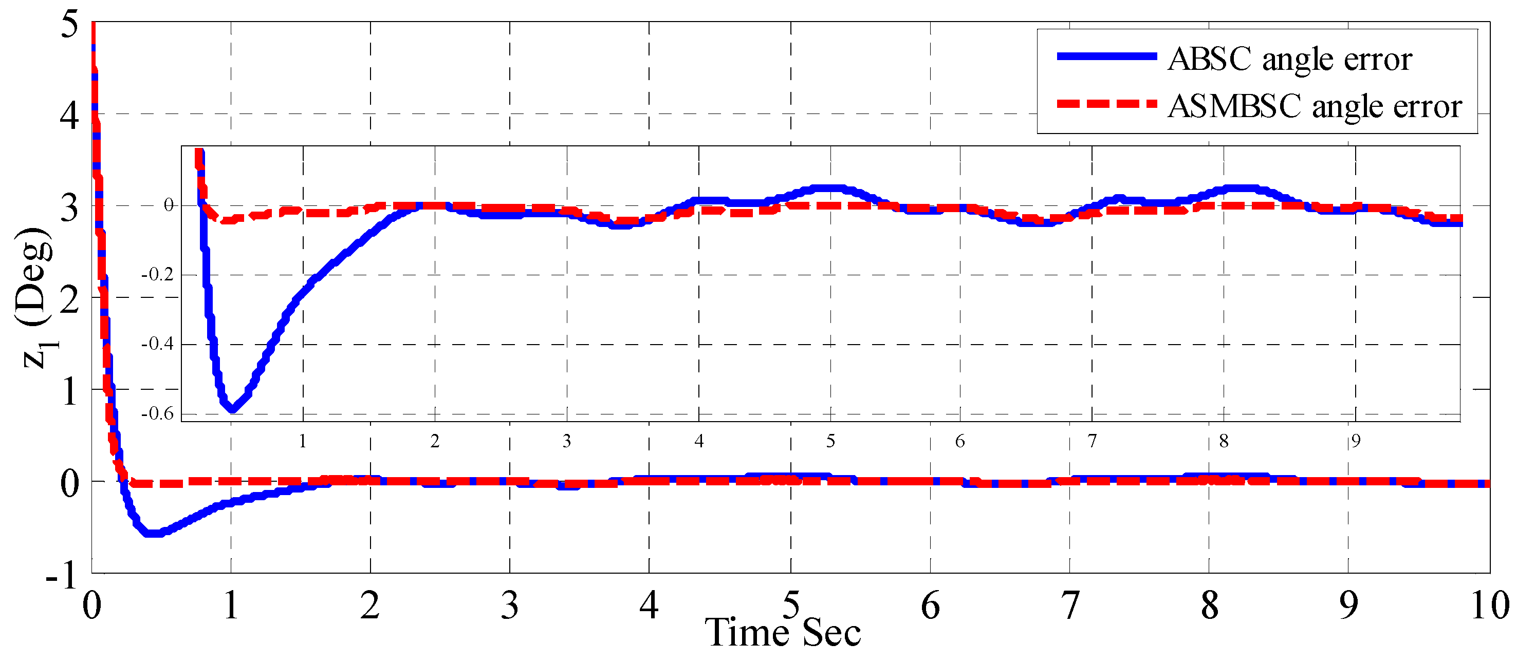
| Tracking Error | Time | Variance | ||||
| 0.5 | 3 | 5 | 8 | 10 | ||
| ABSC | −0.6 | −0.02 | 0.05 | 0.04 | 0.27 | 0.2562 |
| ASMBSC | −0.04 | 0 | 0.001 | 0 | 0.1 | 0.1316 |
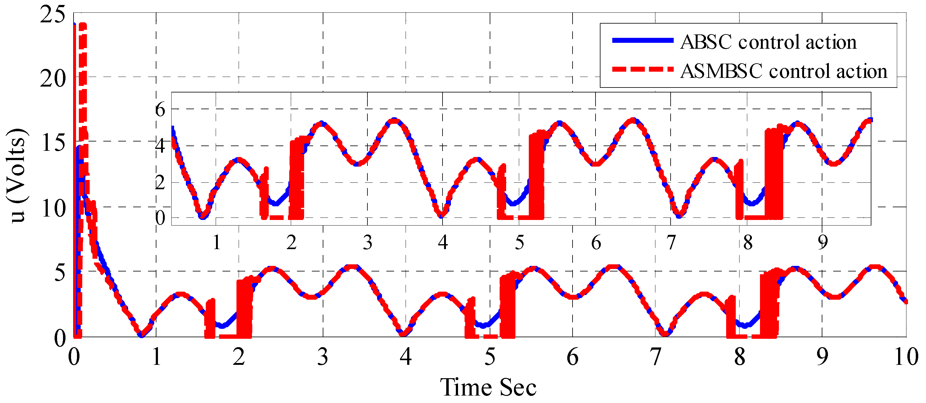
| Control Action | Time | Variance | ||||
| 0.1 | 2 | 5 | 8 | 10 | ||
| ABSC | 14.5 | 1.1 | 1.2 | 0.1 | 3.7 | 10.3 |
| ASMBSC | 24 | 0 | 0 | 0.1 | 3.7 | 11.7 |
© 2019 by the authors. Licensee MDPI, Basel, Switzerland. This article is an open access article distributed under the terms and conditions of the Creative Commons Attribution (CC BY) license (http://creativecommons.org/licenses/by/4.0/).
Share and Cite
Humaidi, A.J.; Hameed, A.H. Design and Comparative Study of Advanced Adaptive Control Schemes for Position Control of Electronic Throttle Valve. Information 2019, 10, 65. https://doi.org/10.3390/info10020065
Humaidi AJ, Hameed AH. Design and Comparative Study of Advanced Adaptive Control Schemes for Position Control of Electronic Throttle Valve. Information. 2019; 10(2):65. https://doi.org/10.3390/info10020065
Chicago/Turabian StyleHumaidi, Amjad J., and Akram H. Hameed. 2019. "Design and Comparative Study of Advanced Adaptive Control Schemes for Position Control of Electronic Throttle Valve" Information 10, no. 2: 65. https://doi.org/10.3390/info10020065
APA StyleHumaidi, A. J., & Hameed, A. H. (2019). Design and Comparative Study of Advanced Adaptive Control Schemes for Position Control of Electronic Throttle Valve. Information, 10(2), 65. https://doi.org/10.3390/info10020065