Abstract
This paper investigates energy harvesting based multiuser system with large-scale distributed antennas, where a large number of remote antenna units (RAUs) are evenly separated across multiple circles. An efficient wireless energy and information transmission protocol is proposed. To save the signaling and the radio frequency chains overheads, the RAU with the shortest distance towards a user equipment (UE) is employed for the downlink wireless energy transfer (WET). In the uplink phase, we analyze the probability of wireless information transmission (WIT) of UEs. Then, linear zero-forcing detection and minimum-mean-square error are used to separate the data information among all the UEs that satisfy the requirement of WIT. The asymptotic throughput for an arbitrary UE is derived in closed-form. The time fraction used for the WET is optimized through maximizing the asymptotic throughput. Numerical and simulation results are given to verify the theoretical analysis, and bring to light the time fraction planning and the RAUs deployment for the system.
1. Introduction
As the key technology of the fifth-generation (5G), massive multiple-input multiple-output (MIMO) has been pervasively studied in recent years [1]. With hundreds of antennas equipped, massive MIMO can achieve extremely high data rates, spectrum efficiency, and energy efficiency [2,3]. According to the law of very long vectors, transmission channels for different users in massive MIMO are orthogonal to each other, which simplifies the system from a mathematical point of view [4,5]. By employing spatial temporal linear equalizers in wireless sensor networks, such as zero-forcing (ZF) and minimum-mean-square error (MMSE), multi-user interference can be mitigated [6,7,8,9]. However, it is reported that massive MIMO system is expected to support billions of wireless user equipments (UEs), which leads to huge energy consumption and massive greenhouse gas pollution [10].
On the other hand, the lifetime of batteries seriously limits the performance of wireless networks [11]. In the past decades, the energy density and size of batteries have not been improved significantly. Fortunately, wireless energy transfer (WET) or energy harvesting (EH), which can harvest energy from ambient radio frequency (RF) resources has emerged as a prospective technique to provide continuous power supply for UEs in the wireless environment. The authors in reference [12] have considered single-antenna UEs that harvest energy from hybrid data-and-energy access point, where frame-based transmissions is employed in the upcoming uplink training and information transmission. The work of authors in reference [13] employs the matched-filter precoder to maximize the minimum harvested energy among energy users for massive MIMO. In general, the energy harvesting efficiency is really sensitive to the transmission distance [14,15,16]. In order to enhance the energy harvesting efficiency, beamforming and EH zone have been employed in references [12,17,18]. As the average transmission distance between transmitters and receivers in distributed antenna system (DAS) is much smaller than that in co-located based MIMO, WET is more feasible in DAS. The antennas deployment in massive DAS is geographically separated in which antennas are defined as the remote antenna units (RAUs). Theses RAUs in the cell are connected to a central processor via high-bandwidth and low-latency backhaul. Compared with the traditional massive MIMO, the coverage of massive DAS is expanded, and the average access between transmitters and receivers can be shortened with this distributed structure [19]. Since all the RAUs in a cell are cooperative for information transmission, DAS with large-scale antennas can be treated as an extension of the centralized massive MIMO. Therefore, research on wireless-powered based massive DAS is a trend toward the next generation communication systems [20].
A single-circle layout massive DAS has been proposed in reference [21] where a large number of RAUs have been deployed across a circle, and the optimal radius of RAU deployment has been gained. Li et al. have studied the massive DAS with multiple-RAU clusters and demonstrated the massive DAS outperforms co-located massive MIMO in terms of achievable rates [22,23]. K. Guo et al. have proposed two DAS enabled transmission strategies for a uniformly distributed massive DAS [24]. Nevertheless, the distances between UEs to the RAUs nearby in the models proposed above are not sufficiently short, which results in inefficient EH. The work in references [20,25] have proposed the uniformly distributed massive DAS. The potential issues on the technologies that could improve WET and wireless in formation transmission (WIT) have also been discussed. However, connecting all the RAUs with the optical fiber are complicated for uniformly distributed massive DAS. Since in massive MIMO, high hardware cost and signaling overheads are produced by an excessive number of RF chains, choosing optimal RAUs for WET towards UEs is an effective way for the issues [26]. Various RAU selection schemes proposed in references [27,28,29,30] can also be applied in the massive DAS. In reference [31], the author designs a feasible wireless-powered massive DAS and employs the best channel quality based antenna selection scheme to analyze the throughput performance for a single user scenario. The multiuser scenario has not been addressed.
In this paper, we consider the multiple-circle layout based massively DAS for multiuser scenario, and study the throughput performance based on EH. This work can be generalized to the ring form layouts, but it cannot be generalized to all the layouts, like grid layout. The contributions of this paper are listed as follows.
- An efficient energy and information transfer transmission scheme is proposed. In the downlink phase, to save the signaling and RF chains overhead, the RAU with the shortest distance towards a UE is selected for the WET. In the uplink phase, the wireless data transmission probability of a UE is developed. Then, the UEs which satisfy the WIT requirement transmit data to the central processor (CP) according to the “harvest-then-transmit” protocol.
- The asymptotic throughput for an arbitrary UE is derived in closed-form by exploiting the ZF detection (ZFD) and the MMSE detection (MMSED) to separate data information among different UEs. Besides, the optimal time fraction used for EH is obtained by maximizing the asymptotic throughput.
- Performance results are provided to validate the theoretical analysis and show the impacts on the throughput performance from various parameters. The average throughput of the cell is also calculated through numerical analysis, which can provide guidelines for the network analysis and optimization.
The rest of this paper is organized as follows. Section 2 introduces the system model which includes the EH model and the WIT model, respectively. In Section 3, we analyze the information transmission probability of the target UE. The asymptotic throughput is derived in Section 4. Section 5 studies the optimal EH time fraction. Numerical and simulation results are provided in Section 6. Finally, Section 7 concludes this paper.
Notation: Boldface lowercase and uppercase letters represent vectors and matrices, respectively. denotes the absolute value, denotes the expectation, denotes the probability, denotes the diagonal matrix, and denotes the Frobenius norm of a vector. The operations and represent the transpose and the conjugate transpose of a vector, respectively.
2. System Model
With the development of internet of things, the lifetime of batteries has much more effects on terminals application. Fortunately, energy harvesting is an effective technique to prolong the lifetime of batteries. Since energy harvesting is sensitive to the propagation distance, the transform of circle layout based massive distributed antenna system is developed [32,33], i.e., multiple-circle layout, to reduce the distance between users and antenna modules. With the angle between two adjacent RAUs uniformly spread in a circle, this structure is equivalent to one dimensional, and the computational complexity of the system is greatly reduced. Therefore, this multiple-circle layout has a good balance between the tractability of theoretical analysis and practicality. In addition, omnidirectional antennas are adopted to get full coverage.
In a macrocell, we assume the system has circles with radius , respectively, and they are all connected to a CP via optical backhaul, as shown in Figure 1. In this network, the power beacons which can provide wireless power are tied up to the existing infrastructure of the low-cost antennas [27], forming the modified RAUs. RAUs are evenly distributed across these circles. The CP in the cell has the ability of a base station and processes signals in a centralized way. Compared with stochastic process-based layout and grid layout, this architecture simplifies the RAUs connections in the implement point of view, which makes performance analysis tractable as the topology is equivalent to a one dimensional network. Throughout this paper, the channel state information in both uplink and downlink can be known at the receiver. Signals are assumed to experience frequency nonselective fading.
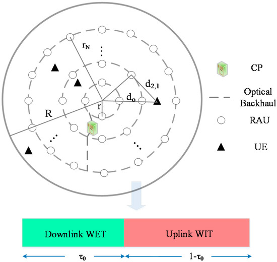
Figure 1.
The system model of wireless-powered based massive distributed antenna system.
We denote as the m-th RAU in the cell, where . Each UE and RAU is assumed to be equipped with one omnidirectional antenna, and the number of the UEs is (). The small-scale fading for uplink and downlink between and its serving UE are denoted as and , respectively, where . The normalized time parameter is divided into two time fractions, i.e., () for the downlink WET phase and for the uplink WIT phase. The specific transmission protocol is defined as follows:
- Downlink WET: In , each UE harvests energy from the selected RAU with the shortest distance.
- Uplink WIT: Firstly, we analyze the information transmission probability of a UE. Only if the power used for information transmission in is no less than the transmit sensitivity, the UE can send its data to the CP at threshold power. To separate different data information among () UEs, ZFD is employed.
2.1. WET Model
We select the k-th UE as the target user. Since the WET technique is sensitive to distance, the UE select the RAU with the shortest distance, , for energy harvesting, i.e.,
Let be the transmit information symbol which satisfies . The Rayleigh fading factor , the path-loss can be modeled by , where is the access distance from to the UE, and is the path-loss exponent. In this work, the equal power allocation scheme is adopted among all the RAUs. During a given block time, the received signal from the selected RAU at the UE is expressed as
where is the transmit power allocated to each RAU, and is the additive white Gaussian noise.
Suppose the distance among each UE is far enough, the energy transfer effect of the remaining RAUs which are in the WET state on the target UE can be ignored. The energy harvested from the noise can be negligible since the transmit power of an RAU is far beyond the noise. In , The amount of energy harvested by the target UE is given by
where is defined as the energy harvesting efficiency.
2.2. WIT Model
In the downlink EH phase, the energy harvested by UE varies with different UE’s locations. The target UE can transmit data to the CP only when the power harvested in the downlink is greater than the transmit sensitivity, . The uplink path-loss is deemed as due to the symmetry of the propagation path between uplink transmission and downlink transmission. Then, the channel vector between the k-th UE and all the RAUs can be written as
We assume UEs can satisfy the WIT condition in time fraction, then the uplink channel vector can be built.
The random variable is defined as the transmitted symbol of the target UE which satisfies . Therefore, denotes UE data vector. According to the transmission protocol, the received signal at CP can be obtained as
where is the noise vector, and each element is i.i.d., obeying complex Gaussian distribution, i.e., .
In massive MIMO, the receiver can separate each data information among different UEs by utilizing the ZFD and the MMSED [34]. With the ZFD, the received signal vector should be multiplied by the matrix . From Equation (5), we have
where the th element in is
where denotes the column vector of the , and . It is concluded from Equation (7) that the simultaneous signal-to-noise ratio (SNR) can be expressed as .
Similarly, with the MMSED, the received signal vector should be multiplied by the matrix . We assume and , we have
3. Information Transmission Probability for a UE
Let , since is Rayleigh distributed, is exponentially distributed. Therefore, the cumulative distribution function (CDF) of can be expressed as
where , and .
Since the energy harvested in the downlink phase is used for the circuit operation and information transmission, we define as the proportion of energy used for the information transmission. Then, the available transmit power for the target UE is written as
When is greater than the threshold power , the UE can transmit its data in the remaining time fraction. Thus, the information transmission probability of the target UE can be obtained as
4. Asymptotic Throughput
In time fraction, UEs are assumed to satisfy the data transmission requirement. The uplink throughput of the th UE with ZFD can be expressed as
where
And the uplink throughput of the kth UE with MMSED can be obtained as
where
Without loss of generality, we take the derivations with ZFD for instance in the following. By exploiting the advantages of massive MIMO, such as the channel hardening and the asymptotic orthogonality of user channels [35,36,37], the small-scale fading parameters can be averaged out, and the interference among the UEs can be eliminated. In what follows, we study the asymptotic throughput of the target UE as the number of RAUs tends to be infinity.
It is noticed from Equation (4) that , where is the path-loss matrix with , and . Therefore, are random vectors of i.i.d. entries with zero mean and variance. The eighth order moment of the k-th entry is , which is of order when , whose elements are independent of . Since is independent of , we can follow lemma 4 and lemma 5 of reference [38] and obtain the following results:
and
Applying Equations (16) and (17), one obtains
Let , since , we have
then, the element from the th column and the th row of matrix is convergent at . Further, we have
Substituting Equations (19) and (11) into Equation (12), we obtain the asymptotic throughput of the th UE as
It is observed from Equation (20) that the throughput is mainly affected by the EH time fraction , the distance between the RAU and its serving UE, and etc.
5. Optimization of Energy Harvesting Time
Theorem 1.
The optimal EH time fraction parameter can be calculated by maximizing the system throughput as
where.
Proof of Theorem 1.
Let ), the asymptotic throughput of the th UE can be rewritten from (17) in the original manuscript as
• Differentiating given in the above equation with respect to , one obtains
Let , we have
the solutions of the above equation can be calculated as
Since , the optimal time fraction should be .
• We now show the solution of is the maximum of . It is concluded from Equation (20) that is a decreasing function of . Therefore,
Notice that and , therefore,
The optimal EH time fraction can be calculated by maximizing as . □
The result of Theorem 1, i.e., as a function of is shown in Figure 2. Since , the optimal EH time fraction depends on the transmit power of a RAU, the threshold power, distance between the transceiver, EH efficiency, etc. If the distance between the RAU and its serving UE is farther, the throughput of a UE should be maximized by harvesting energy for much more time. In the wireless-powered based massive DAS, signals will experience bidirectional path-loss, and the channel gain related to those RAUs far away from the UE can be ignored. As a result, the throughput performance is improved to a small degree as the number of RAUs increases.
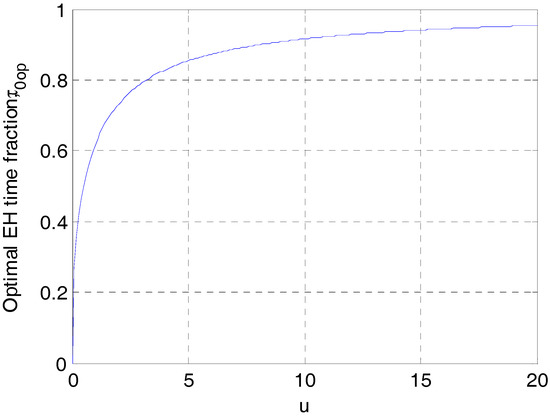
Figure 2.
The optimal energy harvesting (EH) time fraction as a function of .
6. Numerical Results
In this section, we present numerical results to demonstrate the throughput performance for wireless-powered based massive DAS, and give Monte Carlo simulations to validate the theoretical results. Without loss of generality, we analyze the throughput performance with ZFD. The impacts of various parameters, such as the locations of the UE, the number of circles, the number of the RAUs, as well as the EH time fraction on the throughput performance are revealed by numerical analysis. In the simulations, unless stated otherwise, the cellular radius is set as meters, the number of circles is . With this circular pattern layout, the distance between any two adjacent circles is set to be , where is the radiant radius of the marcocell. It is assumed that RAUs with single-antenna are uniformly distributed across the inner circle, and the th () circle has RAUs. Thus, the total number of RAUs should be . The distance between the UE and the cell center is denoted as , the angle between the direction from the UE to the cell center and the horizon direction is denoted as . The path-loss exponent is , the number of RAU in the first circle is , the EH efficiency is , the proportion of information transmission is , the normalized time fraction for EH is , the transmit power of each RAU is W, the power spectral noise is dBm, the threshold power is mW, and the angles between the direction of the UE to the cell center and horizontal direction is .
Figure 3a,b show the property of information transmission probability of a UE versus the EH time fraction, and the ratio of RAU transmit power and threshold power, respectively . In this simulation, the number of circles is set to be . As expected, the simulation results correspond to Equation (10). It is also observed from Figure 3a that the probability increases with the growth of at m, because the more energy harvested by the UE in the downlink, the larger probability that the available transmit power for the target UE achieves the threshold power. From Figure 3b, we observe that the information transmission probability in uplink increases with the growth of the value of . This is explained by the fact that when the value of is large, the transmit power allocated to the RAU is high or the threshold power preset is low, which increase the probability of data transmission. Further, the information transmission probability varies with the UE at different positions. For instance, as the distance between any two adjacent circles in massive DAS with 15-circle layout is m, the UE located at m has the shortest distance to the selected RAU, leading to larger information transmission probability.
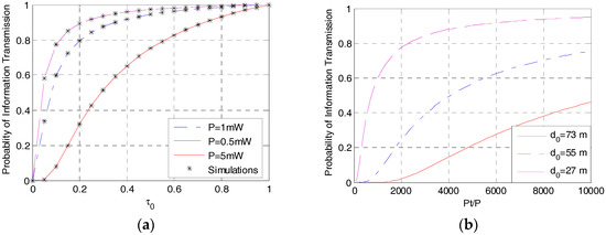
Figure 3.
Information transmission probability versus (a) EH time fraction and (b) ( = 15).
The asymptotic throughput as a function of EH time fraction is plotted in Figure 4. Monte Carlo simulations verify the correctness of the theoretical results, and MMSED outperforms ZFD. As can be seen from this figure that as the EH time fraction increases, the throughput performance improves at first, but gradually decreases after reaching a maximum. This may due to the fact that the increase of the information transmission probability can contribute to the throughput, however, the time fraction used for WIT is shortened, as a result, the gain brought by WET does not surpass the loss brought by WIT. We also find that when the distance between the UE and cell center is 100 m, the optimal EH time fraction can be calculated from Equation (18) as , which matches the simulation result. Further, the UE’s location can also affect the optimal EH time fraction.
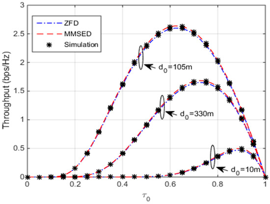
Figure 4.
Throughput as a function of ( ).
The throughput performance versus the transmit power threshold is studied for massive DAS with 10-circle layout and 20-circle layout, respectively, as shown in Figure 5. Both of the two scenarios have nearly the same number of RAUs ( for , and for ). At first, the throughput increases as the threshold power increases, whereas, it may not always increase due to the decrease of the information transmission probability. When the number of the RAU for the two scenarios ( and ) is nearly the same, throughput performance is an increasing function of the number of circles. This is because the average distance between transceiver is reduced with the increase of the number of circles, resulting in the improvement of path-loss. In the practical scenario, however, the optical and radio frequency chains cost can be increased with the growth of circles. Thus, the RAU deployment should be designed according to the stringent requirement of communications and the hardware cost.
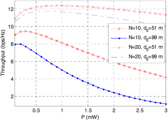
Figure 5.
Throughput versus the threshold power ().
As the theoretical results are validated by the Monte Carlo simulations, the system performance with various parameters settings can be estimated efficiently by the theoretical expressions without resorting to the time-consuming simulations. Figure 6 plots the throughput performance versus the UE’s locations (including the distance and the angle information). Since , m, three peak values of the throughput can be achieved at m, m, and m, respectively, over the radiation range of 0 to 100 m, which matches the numerical results. It is concluded from Figure 6 that the maximal throughput appears when the UE moves along the horizon direction. This can be explained by the fact that the path-loss is the highest when the distance between the UE and its selected RAU at this direction is the shortest, which attributes to the optimal throughput performance.
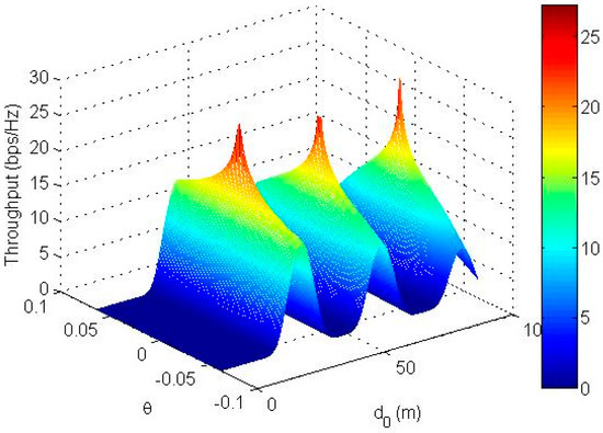
Figure 6.
Throughput versus the user equipment (UE’s) locations ().
We further study the DAS model with 10-circle layout to find the impacts of the number of RAUs on the throughput performance, and compare the proposed massive DAS with the centralized large-scale MIMO (L-MIMO) system at different locations ( m and m), as shown in Figure 7. In general, the throughput performance increases as the number of antennas increases, but it grows slowly when the number of the antennas tends towards infinity. It is also observed from Figure 7 that compared with the proposed massive DAS, the centralized L-MIMO system is more sensitive to the UE’s locations. For instance, when the UE locates near the cell center, the L-MIMO system outperforms the massive DAS, whereas when the UE locates far from the cell center, the L-MIMO achieves very low throughput. Therefore, compared with the centralized L-MIMO, our proposed massive DAS is a more applicable network for energy harvesting to ensure the fairness of the UEs in a cell.
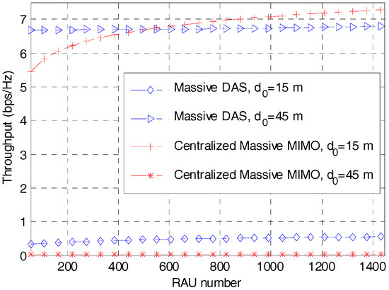
Figure 7.
Throughput versus the number of remote antenna units (RAUs) for massive distributed antenna system (DAS) and centralized large-scale multiple-input multiple-output (L-MIMO).
The average throughput of a cell reveals the insights of the average experience of the UE service, and the optimal EH time scheduling to the downlink WET and the uplink WIT can be estimated with numerical results. The average throughput of a cell can be obtained by averaging over the locations of the target UE, and the detailed derivation is illustrated in Appendix A. Since Equation (28) in Appendix A is a single-integral, theoretical results can be evaluated efficiently exploiting the common mathematical software (e.g., MATLAB). As can be seen from Figure 8 that the average throughput performance has the same variation tendency as that of in Figure 4, and the optimal EH time fraction, , to maximize the average throughput of a cell varies with different number of circles. For instance, the optimal EH time fractions for massive DAS with 10-circle layout (), 14-circle layout (), and 20-circle layout () are 0.21, 0.24, and 0.25, respectively. Moreover, compared with Figure 5 and Figure 7, it is concluded that the number of circles, rather than the number of the RAUs, has much more effect on the system performance.
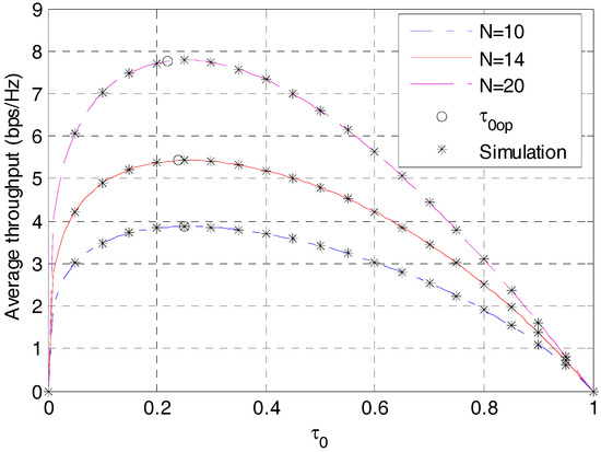
Figure 8.
Average throughput versus the EH time fraction with different number of circles.
7. Conclusions
This paper has studied the throughput performance of wireless-powered based massive DAS in the case of a multiuser scenario. A multiple-circle layout network in which a large number of RAUs are evenly deployed across the circles was considered. We also proposed a RAU selection method for the WET and analyzed the data transmission probability of a UE for the WIT. The closed-form expression of the asymptotic throughput was obtained by exploiting zero-forcing detection. Numerical and simulation results were given to verify the correctness of the theoretical results, and the optimal EH time fraction for an arbitrary UE can be obtained efficiently with numerical results. Our work can be enriched to solve the performance estimation and antennas deployment for MIMO with large-scale distributed antennas.
Author Contributions
Formal analysis, Q.W.; supervision, J.W.; validation, W.G.; writing—original draft, Q.W.; writing—review & editing, Q.W. and W.G.
Funding
This research received no external funding.
Conflicts of Interest
The author declares no conflict of interest.
Appendix A
The geometrical relationships between the UEs and the RAUs are shown in Figure 1. The distance between a typical UE and the cell center is denoted as , the distance between the UE to the th RAU on the th circle, , is denoted as , and the angle between the direction of the UE to the cell center and to the cell center is . Without loss of generality, we assume , therefore, . The path-loss from the UE to is expressed as
Followed by reference [18], when , the average propagation path-loss, , can be obtained by
where is the Legendre function [39].
Supposed UEs are uniformly distributed in the cell, the probability density function (PDF) of the UE’s position can be written as [40]
Applying Equation (A2) into Equation (20), and averaging over the PDF of shown in Equation (A3), one derives the analytical expressions of asymptotic average throughput of a cell as
Since the commonly used mathematical tools like Matlab include integral and Legendre functions, the analytical expressions shown in Equation (A4) can be efficiently evaluated.
References
- Larsson, E.; Edfors, O.; Tufvesson, F.; Marzetta, T. Massive MIMO for next generation wireless systems. IEEE Commun. Mag. 2014, 52, 186–195. [Google Scholar] [CrossRef]
- Guo, K.; Guo, Y.; Ascheid, G. Security-constrained power allocation in MU-massive-MIMO with distributed antennas. IEEE Trans. Wirel. Commun. 2016, 15, 8139–8153. [Google Scholar] [CrossRef]
- Bogale, T.E.; Le, L.B. Massive MIMO and mmwave for 5G wireless hetNet: Potential benefits and challenges. IEEE Veh. Technol. Mag. 2016, 11, 64–75. [Google Scholar] [CrossRef]
- Shirazinia, A.; Dey, S.; Ciuonzo, D.; Rossi, P.S. Massive MIMO for decentralized estimation of a correlated source. IEEE Trans. Signal Process. 2016, 64, 2499–2512. [Google Scholar] [CrossRef]
- Jiang, F.; Chen, J.; Swindlehurst, A.L.; López-Salcedo, J.A. Massive MIMO for wireless sensing with a coherent multiple access channel. IEEE Trans. Signal Process. 2015, 63, 3005–3017. [Google Scholar] [CrossRef]
- Mai, V.V.; Jeong, Y.; Shin, H. Error exponents for distributed detection. IEEE Commun. Lett. 2016, 58, 121–124. [Google Scholar] [CrossRef]
- Ciuonzo, D.; Rossi, P.S.; Dey, S. Massive MIMO channel-aware decision fusion. IEEE Trans. Signal Process. 2015, 63, 604–619. [Google Scholar] [CrossRef]
- Ding, G.; Gao, X.; Xue, Z.; Wu, Y.; Shi, Q. Massive MIMO for distributed detection with transceiver impairments. IEEE Trans. Veh. Technol. 2018, 67, 604–617. [Google Scholar] [CrossRef]
- Ciuonzo, D.; Salvo Rossi, P.; Dey, S. Massive MIMO meets decision fusion: Decode-and-fuse vs. decode-then-fuse. In Proceedings of the 2014 IEEE 8th Sensor Array and Multichannel Signal Processing Workshop (SAM), A Coruna, Spain, 22–25 June 2014; pp. 265–268. [Google Scholar]
- Lee, K.; Yoon, C.; Jo, O.; Lee, W. Joint optimization of spectrum sensing and transmit power in energy harvesting-based cognitive radio networks. IEEE Access 2018, 6, 30653–30662. [Google Scholar] [CrossRef]
- Huang, Y.; Liu, M.; Liu, Y. Energy-efficient SWIPT in IoT distributed antenna systems. IEEE Internet Things J. 2018, 5, 2646–2656. [Google Scholar] [CrossRef]
- Yang, G.; Ho, C.K.; Zhang, R.; Guan, Y.L. Throughput optimization for massive MIMO systems powered by wireless energy transfer. IEEE J. Sel. Areas Commun. 2015, 33, 1640–1650. [Google Scholar] [CrossRef]
- Zhao, L.; Wang, X.; Zheng, K. Downlink hybrid information and energy transfer with massive MIMO. IEEE Trans. Wirel. Commun. 2016, 15, 1309–1322. [Google Scholar] [CrossRef]
- Huang, K.; Lau, V.K.N. Enabling wireless power transfer in cellular networks: Architecture, modeling and deployment. IEEE Trans. Wirel. Commun. 2014, 13, 902–912. [Google Scholar] [CrossRef]
- Tang, H.; Xie, X.; Chen, J. X-duplex relay with self-interference signal energy harvesting and its hybrid mode selection method. In Proceedings of the 27th Wireless and Optical Communication Conference (WOCC), Hualien, Taiwan, 30 April–1 May 2018; pp. 1–6. [Google Scholar]
- Licea, D.B.; Zaidi, S.A.R.; Mclernon, D.; Ghogho, M. Improving radio energy harvesting in robots using mobility diversity. IEEE Trans. Signal Process. 2016, 64, 2065–2077. [Google Scholar] [CrossRef]
- Chen, X.; Wang, X.; Chen, X. Energy-efficient optimization for wireless information and power transfer in large-scale MIMO systems employing energy beamforming. IEEE Wirel. Commun. Lett. 2013, 2, 667–670. [Google Scholar] [CrossRef]
- Zhai, C.; Liu, J.; Zheng, L. Cooperative spectrum sharing with wireless energy harvesting in cognitive radio network. IEEE Trans. Veh. Technol. 2015, 65, 5303–5316. [Google Scholar] [CrossRef]
- Zhai, C.; Liu, L.; Zheng, L. Relay based spectrum sharing with secondary users powered by wireless energy harvesting. IEEE Trans. Commun. 2016, 64, 1875–1887. [Google Scholar] [CrossRef]
- Yuan, F.; Jin, S.; Huang, Y.; Wong, K.; Zhang, Q.T.; Zhu, H. Joint wireless information and energy transfer in massive distributed antenna systems. IEEE Commun. Mag. 2015, 53, 109–116. [Google Scholar] [CrossRef]
- Yang, A.; Jing, Y.; Xing, C.; Fei, Z.; Kuang, J. Performance analysis and location optimization for massive MIMO systems with circularly distributed antennas. IEEE Trans. Wirel. Commun. 2015, 14, 5659–5671. [Google Scholar] [CrossRef]
- Li, J.; Wang, D.; Zhu, P.; You, X. Spectral efficiency analysis of single-cell multi-user large-scale distributed antenna system. IET Commun. 2014, 12, 2213–2221. [Google Scholar] [CrossRef]
- Li, J.; Wang, D.; Zhu, P.; You, X. Spectral efficiency analysis of large-scale distributed antenna system in a composite correlated Rayleigh fading channel. IET Commun. 2015, 9, 681–688. [Google Scholar] [CrossRef]
- Guo, K.; Mukherjee, S.; Ascheid, G. Wireless information and power transfer in MU-massive-MIMO with distributed antennas. In Proceedings of the 2017 International Symposium on Wireless Communication Systems (ISWCS), Bologna, Italy, 28–31 August 2017; pp. 228–233. [Google Scholar]
- Sun, Q.; Jin, S.; Wang, J.; Zhang, Y.; Gao, X.; Wong, K. Downlink massive distributed antenna systems scheduling. IET Commun. 2015, 9, 1006–1016. [Google Scholar] [CrossRef]
- Choi, W.; Andrews, I.G. Downlink performance and capacity of distributed antenna systems in a multicell environment. IEEE Trans. Wirel. Commun. 2007, 6, 69–73. [Google Scholar] [CrossRef]
- Tabassum, H.; Hossain, E. On the deployment of energy sources in wireless-powered cellular networks. IEEE Trans. Commun. 2015, 63, 3391–3404. [Google Scholar] [CrossRef]
- Li, J.; Yan, J.; Zhao, L.; Dong, Q. Antenna selection and transmit beamforming optimisation with partial channel state information in distributed antenna systems. IET Commun. 2014, 8, 2272–2280. [Google Scholar] [CrossRef]
- Li, H.; Koudouridis, G.; Zhang, J. Antenna selection schemes for energy efficiency in distributed antenna systems. In Proceedings of the IEEE International Conference on Communications (ICC), Ottawa, ON, Canada, 10–15 June 2012; pp. 5619–5623. [Google Scholar]
- Wang, Q.; Liu, J.; Zheng, L. Exact error rate of dual-channel receiver with remote antenna unit selection in multicell networks. Ksii Trans. Internet Inf. Syst. 2016, 10, 548–557. [Google Scholar] [CrossRef]
- Wang, Q.; Xiong, H.; Yu, S. Throughput of wireless-powered massive distributed antenna systems over composite fading channels. J. Commun. 2017, 12, 24–31. [Google Scholar] [CrossRef]
- Wang, X.; Zhu, P.; Chen, M. Antenna location design for generalized distributed antenna systems. IEEE Commun. Lett. 2009, 13, 315–317. [Google Scholar] [CrossRef]
- Park, E.; Lee, S.; Lee, I. Antenna placement optimization for distributed antenna systems. IEEE Trans. Wirel. Commun. 2012, 11, 2468–2477. [Google Scholar] [CrossRef]
- Hoydis, J.; Brink, S.; Debbah, M. Massive MIMO in UL/DL cellular systems: How many antennas do we need? IEEE J. Sel. Areas Commun. 2013, 31, 160–171. [Google Scholar] [CrossRef]
- Hochwald, M.; Marzetta, T.; Tarokh, V. Multiple-antenna channel hardening and its implications for rate feedback and scheduling. IEEE Trans. Inf. Theory 2004, 50, 1893–1909. [Google Scholar] [CrossRef]
- Gao, X.; Edfors, O. Linear pre-coding performance in measured very-large MIMO channels. In Proceedings of the IEEE VTC, San Francisco, CA, USA, 5–8 September 2011; pp. 1–5. [Google Scholar]
- Ngo, H.; Larsson, E.; Marzetta, T. Energy and spectral efficiency of very large multiuser MIMO systems. IEEE Trans. Commun. 2013, 61, 1436–1449. [Google Scholar] [CrossRef]
- Wagner, S.; Couillet, R.; Debbah, M.; Slock, D.T.M. Large system analysis of linear precoding in correlated MISO broadcast channels under limited feedback. IEEE Trans. Inf. Theory 2012, 58, 4509–4537. [Google Scholar] [CrossRef]
- Gradshteyn, I.S.; Ryzhik, I.M. Table of Integrals, Seires and Products; Academic Press: New York, NY, USA, 2003. [Google Scholar]
- Choi, W.; Kim, J.K. Forward-link capacity of a DS/CDMA system with mixed multivariate sources. IEEE Trans. Veh. Technol. 2001, 50, 737–749. [Google Scholar] [CrossRef]
© 2018 by the authors. Licensee MDPI, Basel, Switzerland. This article is an open access article distributed under the terms and conditions of the Creative Commons Attribution (CC BY) license (http://creativecommons.org/licenses/by/4.0/).