Planar UWB Monopole Antenna with Tri-Band Rejection Characteristics at 3.5/5.5/8 GHz


Abstract
:1. Introduction
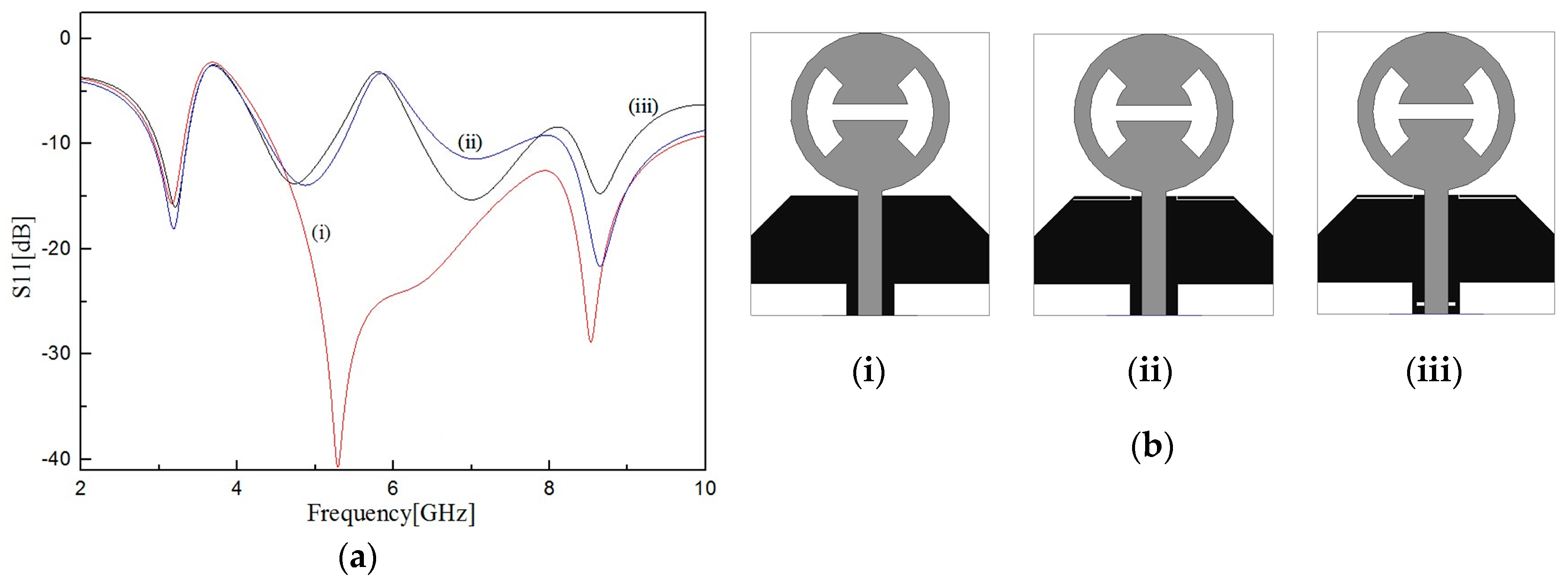
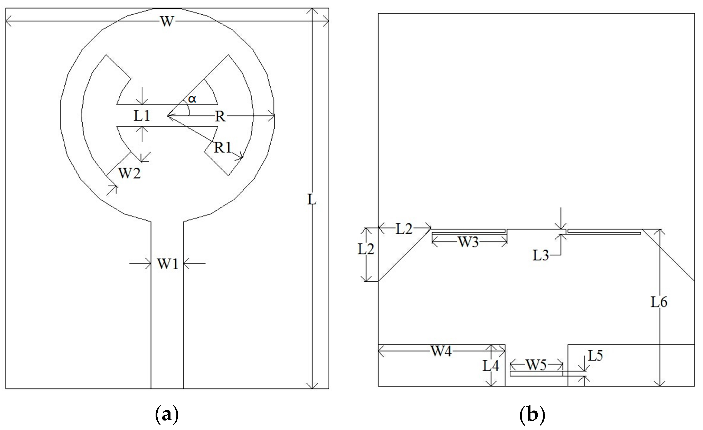
2. Antenna Design
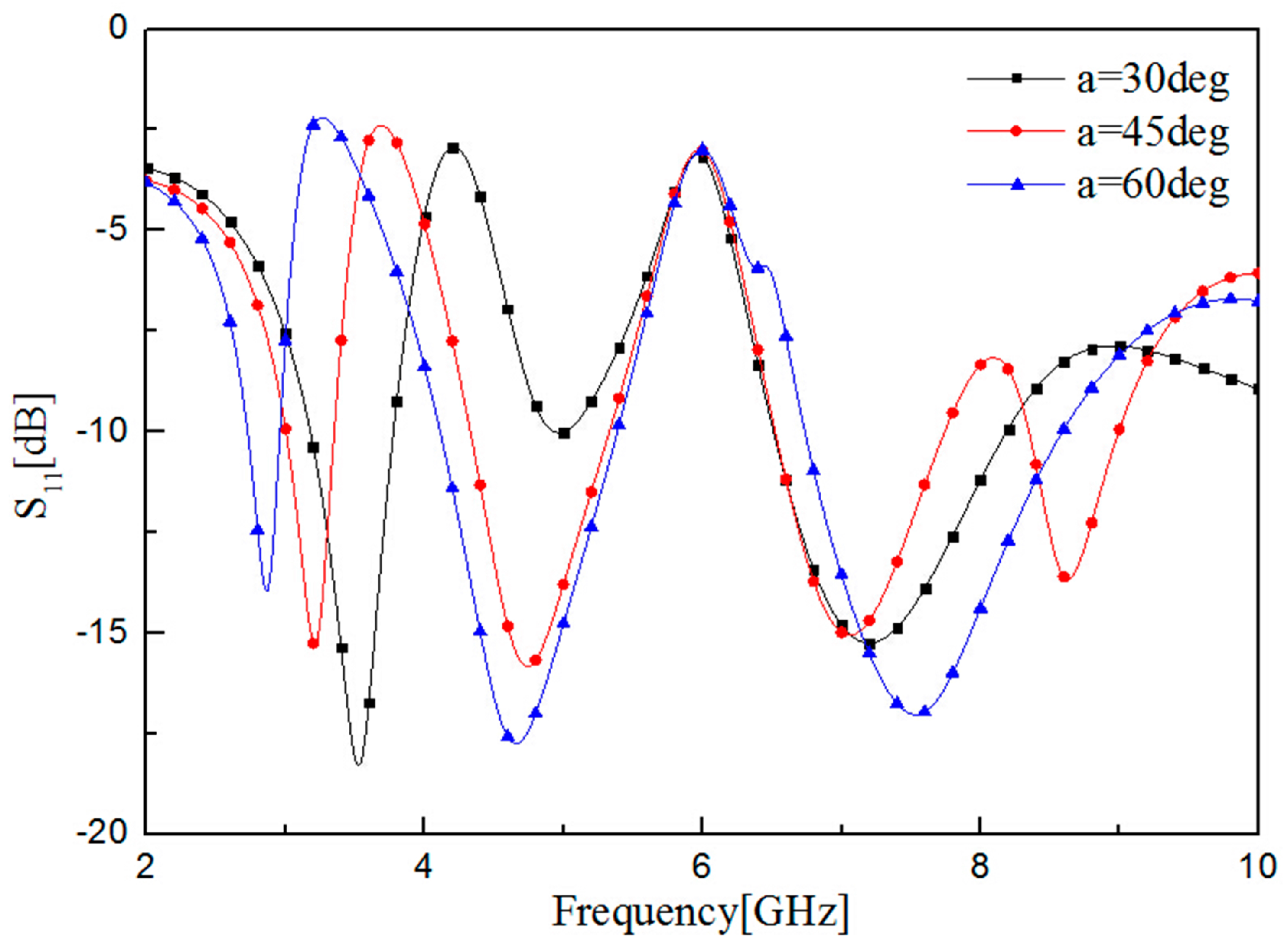
3. Parametric Study
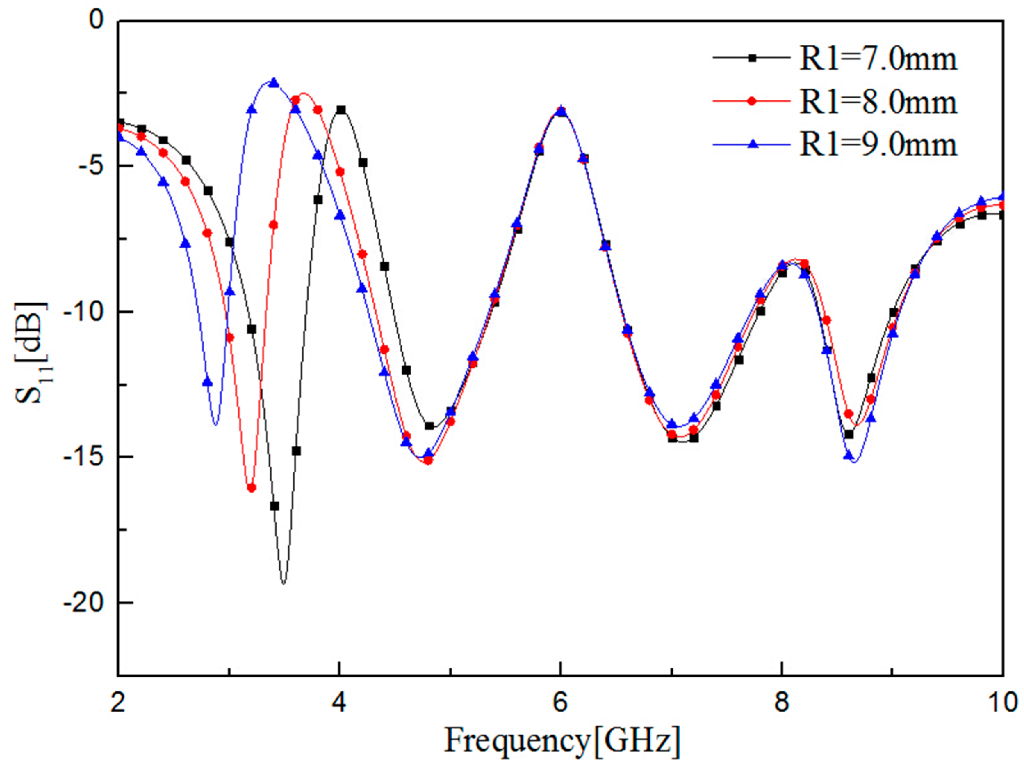
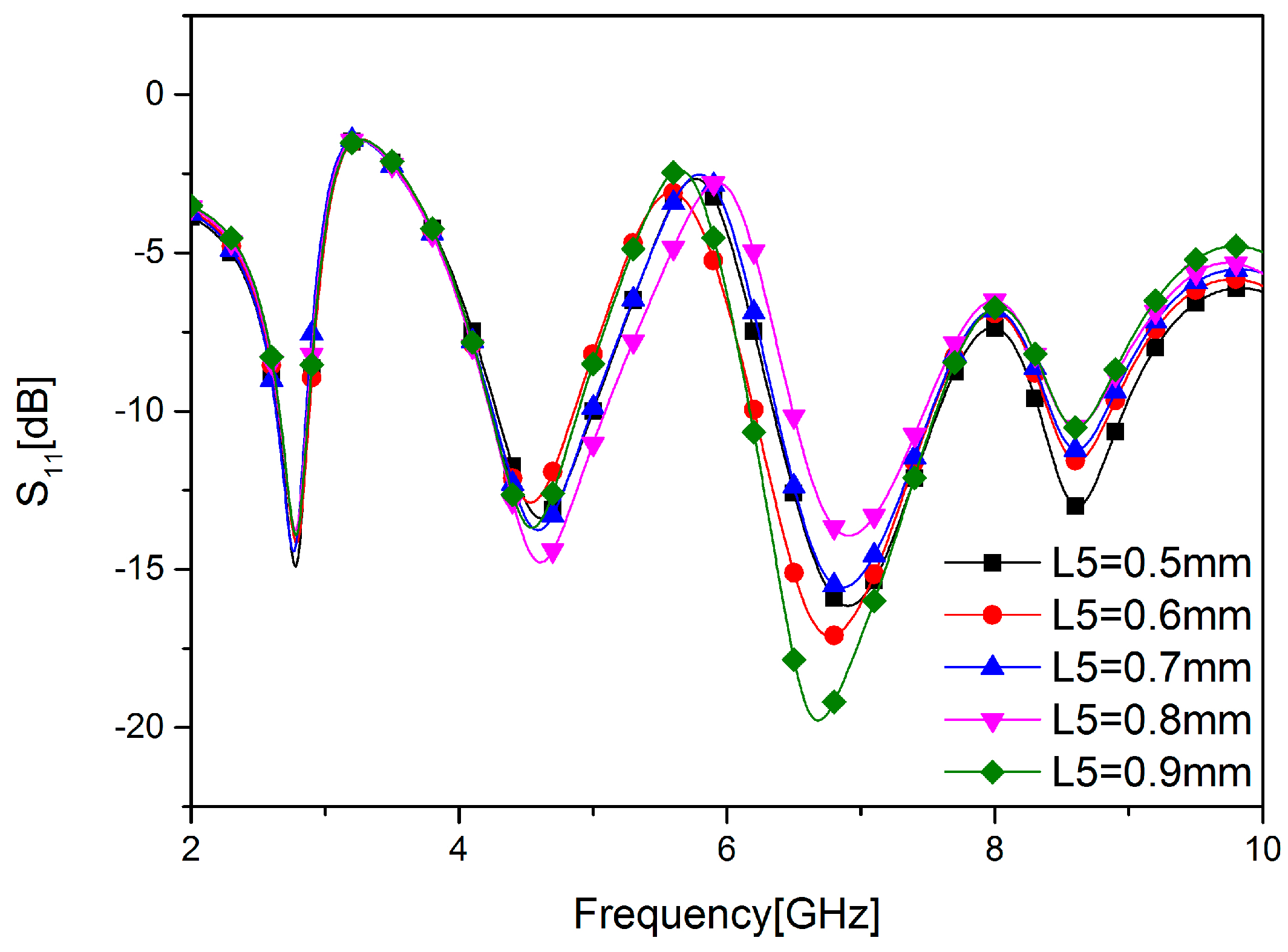
3.1. Variation of Patch Parameters
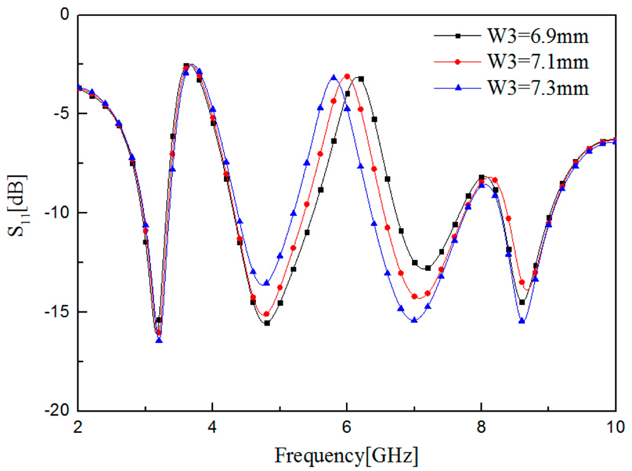
3.2. Variation of Ground Parameters
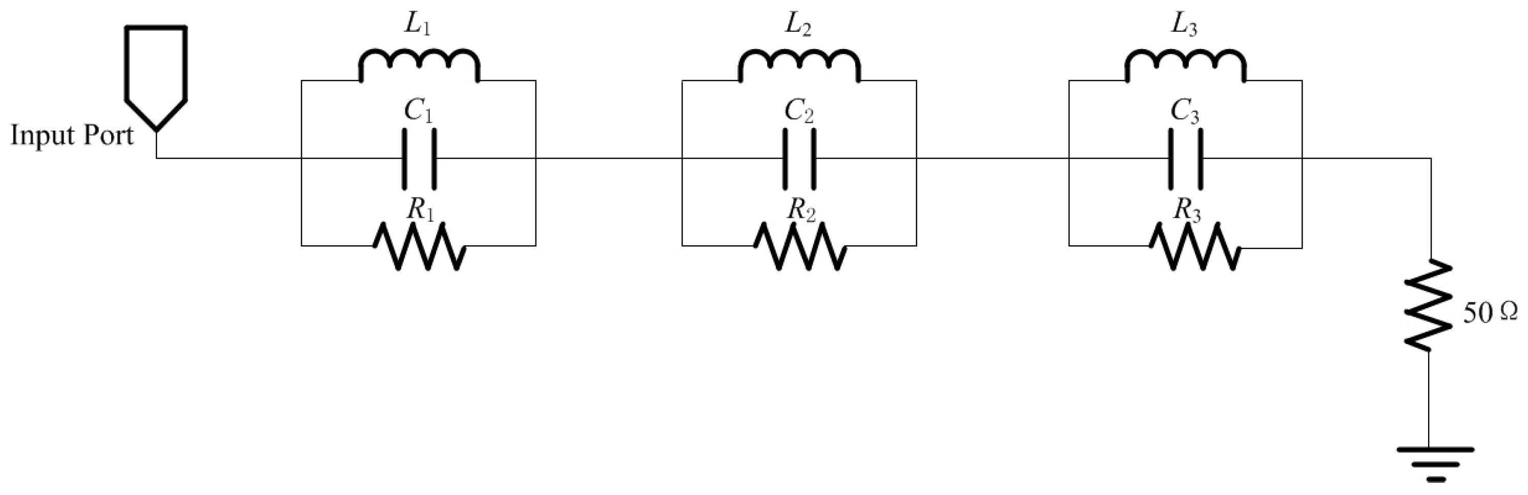
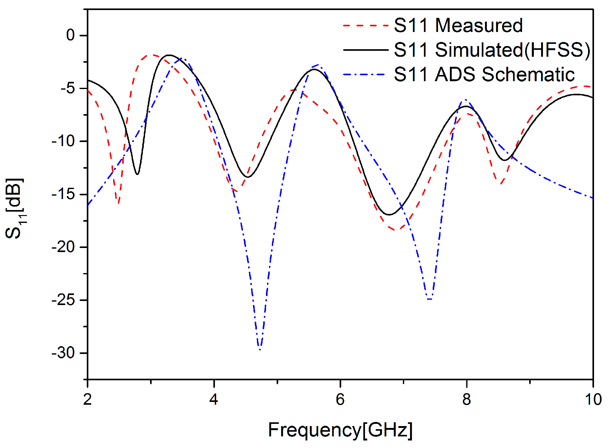
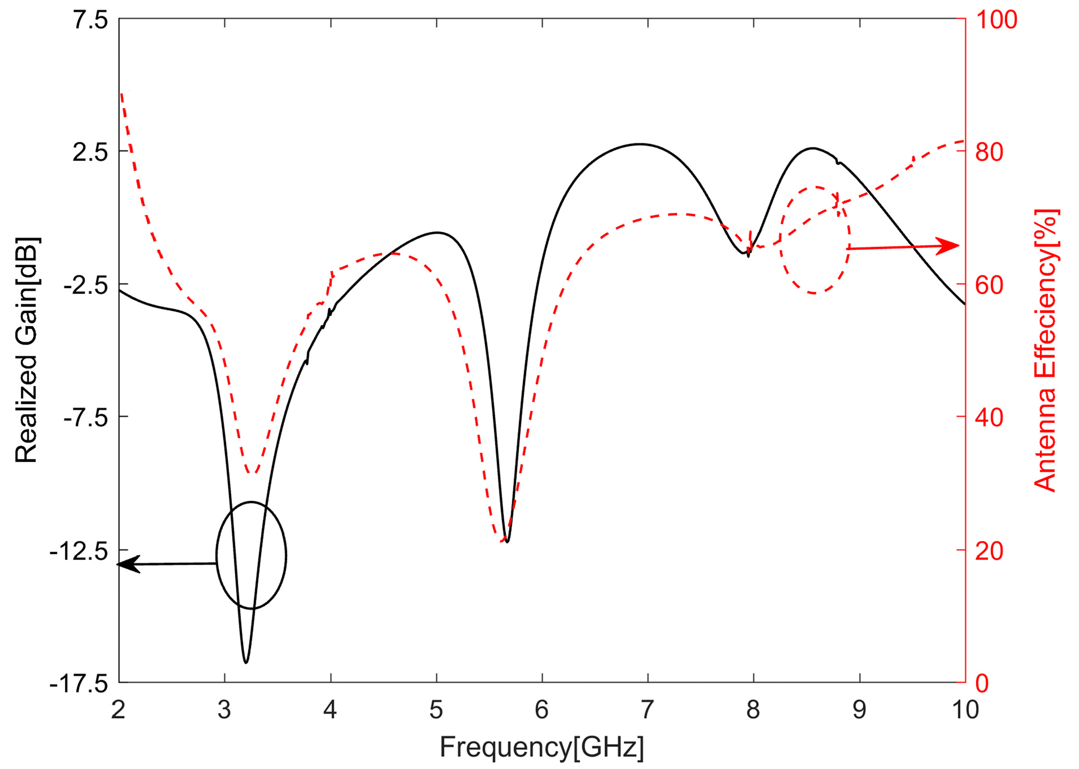
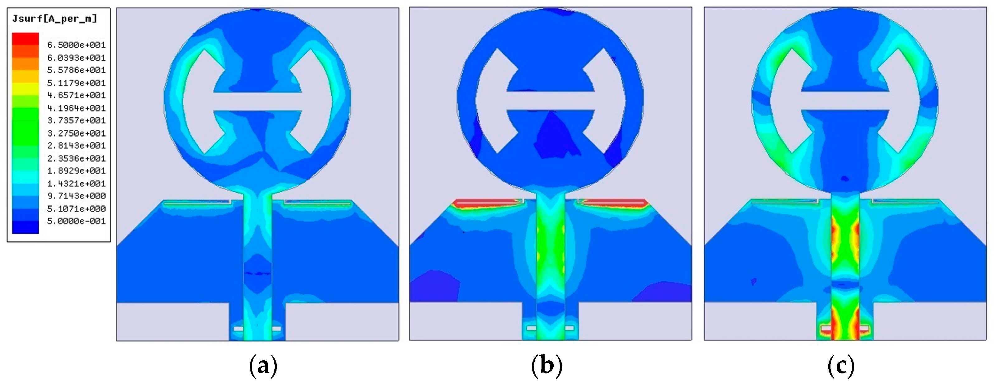
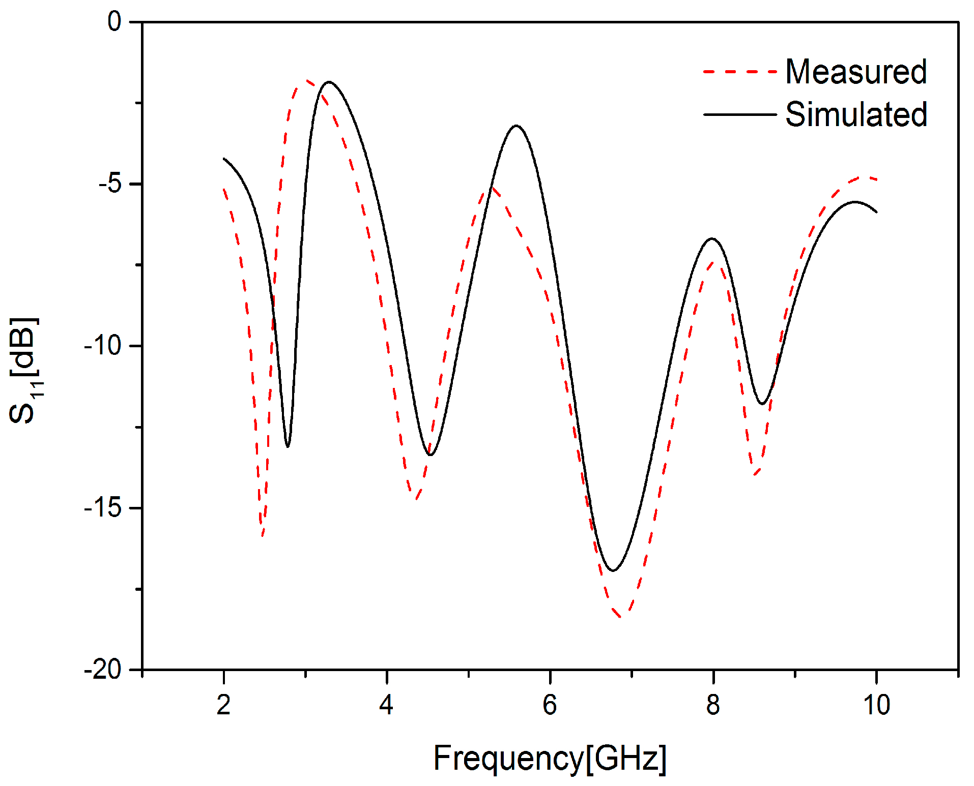
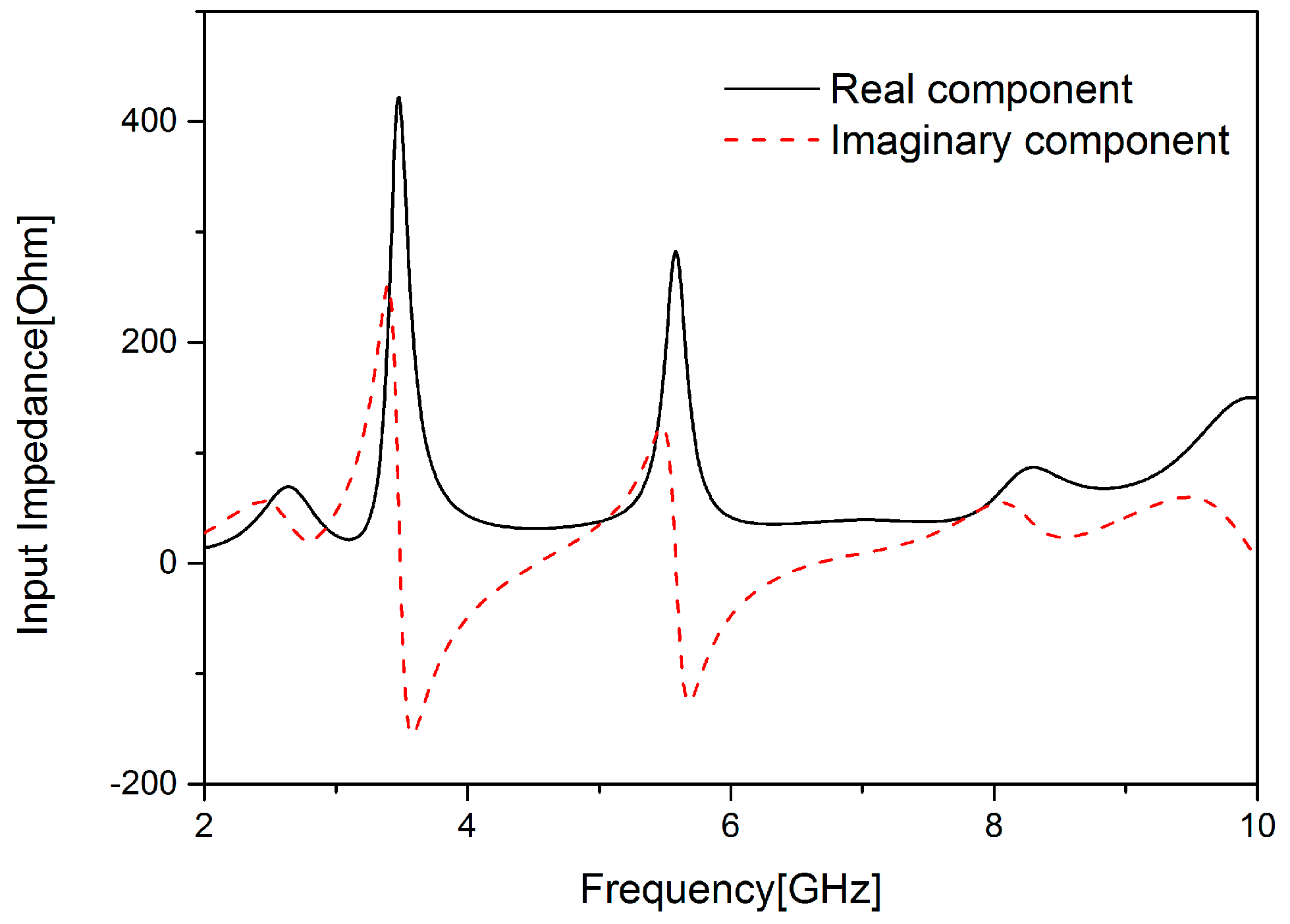
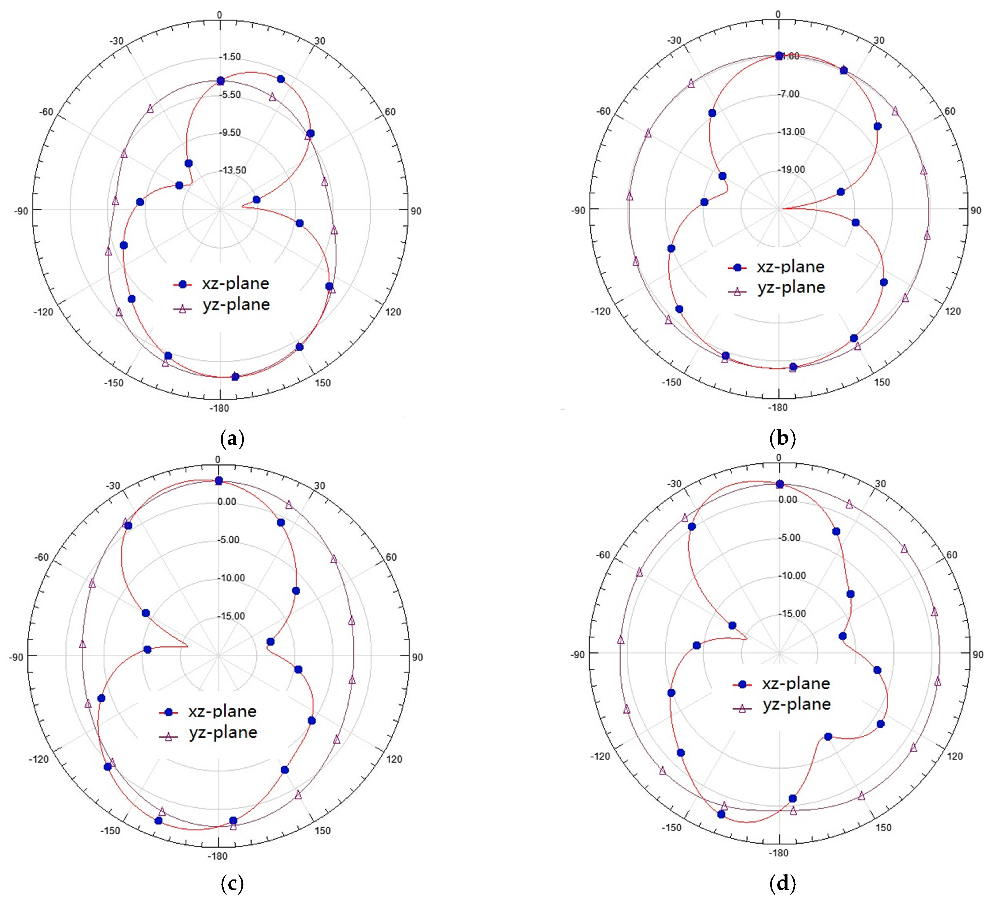
4. Results and Discussion
5. Comparison with Other UWB Antennas with Band-Notched Function
6. Conclusions
Author Contributions
Funding
Conflicts of Interest
References
- Zhang, J.; Orlik, P.V.; Sahinoglu, Z.; Molisch, A.F.; Kinney, P. UWB systems for wireless sensor networks. Proc. IEEE 2009, 97, 313–331. [Google Scholar] [CrossRef]
- Zhu, J.; Li, S.; Feng, B.; Deng, L.; Yin, S. Compact dual-polarized UWB quasi-self-complementary MIMO/diversity antenna with band-rejection capability. IEEE Antennas Wirel. Propag. Lett. 2016, 15, 905–908. [Google Scholar] [CrossRef]
- Bilal, M.; Saleem, R.; Abbasi, H.H.; Shafique, M.F.; Brown, A.K. An FSS based non-planar quad element UWB-MIMO antenna system. IEEE Antennas Wirel. Propag. Lett. 2017, 16, 987–990. [Google Scholar] [CrossRef]
- Arifin, F.; Saha, P.K. Minimization of path loss for a UWB communication link in a wireless capsule endoscopy system using antenna parameters. In Proceedings of the 2017 IEEE Region 10 Humanitarian Technology Conference (R10-HTC), Dhaka, Bangladesh, 21–23 December 2017. [Google Scholar]
- Rahman, M.; NaghshvarianJahromi, M.; Mirjavadi, S.; Hamouda, A. Resonator Based Switching Technique between Ultra Wide Band (UWB) and Single/Dual Continuously Tunable-Notch Behaviors in UWB Radar for Wireless Vital Signs Monitoring. Sensors 2018, 18, 3330. [Google Scholar] [CrossRef] [PubMed]
- Donghyun, K. Performance of UWB Wireless Telecommunication Positioning for Disaster Relief Communication Environment Securing. Sustainability 2018, 10, 3857. [Google Scholar]
- Thomas, T.; Anh, D.; Khan, W. An Ultra-Wideband Frequency System for Non-Destructive Root Imaging. Sensors 2018, 18, 2438. [Google Scholar]
- Rahman, M.; NaghshvarianJahromi, M.; Mirjavadi, S.; Hamouda, A. Bandwidth Enhancement and Frequency Scanning Array Antenna Using Novel UWB Filter Integration Technique for OFDM UWB Radar Applications in Wireless Vital Signs Monitoring. Sensors 2018, 18, 3155. [Google Scholar] [CrossRef]
- Kerkhoff, A.; Ling, H. Design of a planar monopole antenna for use with ultra-wideband (UWB) having a band-notched characteristic. In Proceedings of the IEEE Antennas and Propagation Society International Symposium. Digest, Conjunction with: USNC/CNC/URSI North American Radio Sci. Meeting (Cat. No.03CH37450), Columbus, OH, USA, 22–27 June 2003. [Google Scholar]
- Schantz, H.G.; Wolenec, G.; Myszka, E.M.I. Frequency notched UWB antenna. In Proceedings of the IEEE Conference on Ultra Wideband Systems and Technologies, Reston, VA, USA, 16–19 November 2003. [Google Scholar]
- Kim, Y.; Kwon, D.H. CPW-fed planar ultra-wideband antenna having a frequency band notch function. Electron. Lett. 2004, 40, 403–405. [Google Scholar] [CrossRef]
- Huang, C.Y.; Huang, S.A.; Yang, C.F. Band-notched ultra-wideband circular slot antenna with inverted C-shaped parasitic strip. Electron. Lett. 2008, 44, 891–892. [Google Scholar] [CrossRef]
- Tang, Z.J.; Wu, X.F.; Zhan, J. Novel compact band-notched UWB antenna using convex-shaped slot patch. Microw. Opt. Technol. Lett. 2015, 57, 201–203. [Google Scholar] [CrossRef]
- Chu, Q.X.; Yang, Y.Y. A compact ultrawideband antenna with 3.4/5.5 GHz dual band-notched characteristics. IEEE Trans. Antennas Propag. 2008, 56, 3637–3644. [Google Scholar] [CrossRef]
- Li, W.T.; Yong, Q.H.; Feng, W.; Shi, X.W. Planar antenna for 3G/bluetooth/WiMAX and UWB applications with dual band-notched characteristics. IEEE Antennas Wirel. Propag. Lett. 2012, 11, 61–64. [Google Scholar]
- Mehranpour, M.; Nourinia, J.; Ghobadi, C.; Ojaroudi, M. Dual band-notched square monopole antenna for ultrawideband applications. IEEE Antennas Wirel. Propag. Lett. 2012, 11, 172–175. [Google Scholar] [CrossRef]
- Srivastava, G.; Mohan, A. A planar UWB monopole antenna with dual band notched function. Microw. Opt. Technol. Lett. 2015, 57, 99–104. [Google Scholar] [CrossRef]
- Yeo, J. Wideband circular slot antenna with tri-band rejection characteristics at 2.45/5.45/8 GHz. Microw. Opt. Technol. Lett. 2010, 50, 1910–1914. [Google Scholar] [CrossRef]
- Deng, J.Y.; Yin, Y.Z.; Zhou, S.G.; Liu, Q.Z. Compact ultra-wideband antenna with tri-band notched characteristic. Electron. Lett. 2008, 44, 1231–1233. [Google Scholar] [CrossRef]
- Rahman, M.; Ko, D.S.; Park, J.D. A compact multiple notched ultra-wide band antenna with an analysis of the CSRR-TO-CSRR coupling for portable UWB applications. Sensors 2017, 17, 2174. [Google Scholar] [CrossRef]
- Rahman, M.; Park, J.D. The Smallest Form Factor UWB Antenna with Quintuple Rejection Bands for IoT Applications Utilizing RSRR and RCSRR. Sensors 2018, 18, 911. [Google Scholar] [CrossRef]
- Sarkar, D.; Srivastava, K.V.; Saurav, K. A Compact Microstrip-Fed Triple Band-Notched UWB Monopole Antenna. IEEE Antennas Wirel. Propag. Lett. 2014, 13, 396–399. [Google Scholar] [CrossRef]
- Wang, J.; Wang, Z.; Yin, Y.; Liu, X. UWB Monopole Antenna with Triple Band-Notched Characteristic Based on a Pair of Novel Resonators. Prog. Electromagn. Res. C 2014, 49, 1–10. [Google Scholar] [CrossRef]
- Mohammed, H.J.; Abdullah, A.S.; Ali, R.S.; Abd-Alhameed, R.A.; Abdulraheem, Y.I.; Noras, J.M. Design of a uniplanar printed triple band-rejected ultra-wideband antenna using particle swarm optimisation and the firefly algorithm. IET Microw. Antennas Propag. 2016, 10, 31–37. [Google Scholar] [CrossRef] [Green Version]
- Cai, Y.Z.; Yang, H.C.; Cai, L.Y. Wideband Monopole Antenna with Three Band-Notched Characteristics. IEEE Antennas Wirel. Propag. Lett. 2014, 13, 607–610. [Google Scholar]
- Rahman, M.; Khan, W.T.; Imran, M. Penta-notched UWB antenna with sharp frequency edge selectivity using combination of SRR, CSRR, and DGS. AEU-Int. J. Electron. Commun. 2018, 93, 116–122. [Google Scholar] [CrossRef]


| W | L | α | R | R1 | W1 | L1 | W2 |
| 30 | 35.5 | π/4 | 10 | 8 | 3 | 2 | 3.2 |
| L2 | W3 | L3 | W4 | L4 | W5 | L5 | L6 |
| 5 | 7.3 | 0.5 | 12 | 4 | 5.5 | 0.7 | 15 |
| Circuit | BW (MHz) | Q0 | R (Ω) | L (pH) | C (pF) |
|---|---|---|---|---|---|
| 1 | 144 | 24.3 | 357 | 664.51 | 3.11 |
| 2 | 153 | 36.6 | 268 | 208.17 | 3.88 |
| 3 | 251 | 32.4 | 89 | 53.99 | 7.51 |
| Reference | Size (mm) | Notched Band (GHz) | Remarks |
|---|---|---|---|
| [18] | 70 × 80 | 2.4–2.5, 4.0–6.0, 8.0–8.5 | Antenna had three notched bands, but size was too large, and it did not reject WiMAX band |
| [19] | 24 × 35 | 3.4–4.15, 5.3–6.2, 6.8–7.7 | Antenna had three notched bands, but it did not reject complete WiMAX band and complete WLAN band |
| [20] | 28 × 30 | 3.3–3.6, 4.5–4.7, 5.15–5.35, 5.7–5.825 | Antenna had four notched bands, but it did not reject the band for X-band satellite applications operating near 8 GHz |
| [22] | 35 × 35 | 2.95–3.72, 5.12–6.07, 8.04–8.65 | Antenna had three notched bands, but it had a larger size |
| [23] | 36.6 × 26 | 3.36–3.75, 5.15–6.0, 7.07–8.7 | Antenna had three notched bands, but it did not reject complete WiMAX band |
| [24] | 30 × 30 | 3.3–3.7, 5.15–5.825, 7.25–7.475 | Antenna had three notched bands, but it did not reject the band for X-band satellite applications operating near 8 GHz |
| [25] | 27 × 30.5 | 3.36–3.88, 4.96–6.23, 7.9–8.7 | Antenna had three notched bands, but it did not reject complete WiMAX band |
| This Work | 35.5 × 30 | 2.59–4.01, 4.73–6.11, 7.68–8.40 | Antenna had three notched bands, and rejected complete WiMAX band, complete WLAN band and the band for X-band satellite applications operating near 8 GHz |
© 2018 by the authors. Licensee MDPI, Basel, Switzerland. This article is an open access article distributed under the terms and conditions of the Creative Commons Attribution (CC BY) license (http://creativecommons.org/licenses/by/4.0/).
Share and Cite
Dong, J.; Zhuang, X.; Hu, G. Planar UWB Monopole Antenna with Tri-Band Rejection Characteristics at 3.5/5.5/8 GHz. Information 2019, 10, 10. https://doi.org/10.3390/info10010010
Dong J, Zhuang X, Hu G. Planar UWB Monopole Antenna with Tri-Band Rejection Characteristics at 3.5/5.5/8 GHz. Information. 2019; 10(1):10. https://doi.org/10.3390/info10010010
Chicago/Turabian StyleDong, Jian, Xin Zhuang, and Guoqiang Hu. 2019. "Planar UWB Monopole Antenna with Tri-Band Rejection Characteristics at 3.5/5.5/8 GHz" Information 10, no. 1: 10. https://doi.org/10.3390/info10010010
APA StyleDong, J., Zhuang, X., & Hu, G. (2019). Planar UWB Monopole Antenna with Tri-Band Rejection Characteristics at 3.5/5.5/8 GHz. Information, 10(1), 10. https://doi.org/10.3390/info10010010