1. Introduction
Green energy technology is a key factor affecting the sustainable development of the Earth. The green energy resources, such as wind, sun, ocean current, wave, and tidal current, are effectively utilized to aid the low carbon society scenarios. Ocean current is one of the potential energies to be exploited. There are several different forms of ocean energy that are being investigated as potential sources for power generation [
1,
2,
3,
4]. It is well known that the Kuroshio strong current flowing through the east of Taiwan is an excellent energy resource. The current has a mean velocity of about 1.2~1.53 m/s near the surface. The potential electricity capacity that Taiwan can harvest from it is estimated at about 4 GW. This ocean energy source is too rich and stable to be neglected. However, the seabed beneath the Kuroshio current is almost over 1000 m in the area mentioned above. In addition, it is predictable that a few typhoons will strike Taiwan every year. These two disadvantages must be tackled prior to the current power generation system construction.
Flexible mooring devices are important tools for deep-water deployment and are often used in wave energy converters (WEC), tidal current energy converters (TCEC), and ocean current energy converters (OCEC). The mooring configuration for wave energy converters can be divided into (1) catenary mooring, (2) multi-catenary mooring, (3) taut spread mooring, (4) catenary anchor leg mooring (CALM), and (5) single anchor leg mooring (SALM) [
5]. The ocean current aforementioned power generation field has a flow velocity of about 0.7~2 m/s towards almost one direction. The ocean current turbine converts the kinetic energy of the current into electrical energy. Because the seabed is about 1300 m below the sea surface, the mooring rope is very long. The use of light and high-strength PE mooring ropes is beneficial to construction, while chains and steel ropes are not easy to construct. A lightweight and high-strength PE rope will be straightened under large tension. Wave energy converters (WEC) are different from ocean current power generation in the aspect of flow direction; the first one has a time-varying direction and the latter one has almost one direction. To fix the mooring system, the weight of the chain is an advantage, so chains are often used to secure the wave energy converter. In comparison to the rope and chain, the deformation of a chain is often curvilinear. Obviously, the two mooring systems are different.
The mooring system of the floating wave energy converter (WEC) has a great influence on the efficiency of power generation, the cost of energy transmission, normal operation, reliability, and survivability. The deformation of a mooring chain is often curved, due to its weight, and the analysis of dynamic behaviors with regards to that often requires a numerical method. Therefore, the relevant works of the literature are as follows: Muliawan et al. [
6] determined the extreme responses in the mooring lines of a two-body floating wave energy converter mooring with four catenary cables. Angelelli et al. [
7] investigated the behavior of a wave energy convertor mooring with four spread cables, by using Ansys AQWA software. Chen et al. [
4] investigated the wave-induced motions of a floating WEC with mooring lines, by using the smoothed particle hydrodynamics (SPH) method. Davidson and Ringwood [
5] reviewed the mathematical models for mooring systems for the wave energy converters. Touzon et al. [
8] investigated three different well-known mooring design methods applied to a floating wave energy converter system moored by four catenaries. The three research methods that have been used are linearized frequency domain, based on the quasi-static model of mooring cables, time-domain methods for analyzing catenary models combined with mooring systems, and fully coupled nonlinear time-domain methods. In their study, it is found that the viscous force of the lines significantly affects the performance of the structure with high prestress. The line will have a sudden load, due to the fluctuation of the floating platform, so the tension is greatly affected by the resistance and inertial force. Paduano et al. [
9] proposed the following three mooring line models: a quasi-static method and two dynamic lumped mass methods. The case study is a prototype of a floating oscillating water column WEC, tested in a wave pool with three mooring lines; each line includes a riser and a counterweight. Verification, by applying fairlead displacement and comparing the resulting tensions, showed good consistency. Xiang et al. [
10] proposed a time-domain modeling method coupled with a finite element cable model to study the coupled nonlinear mooring dynamics of a floating buoy in shallow water. Cerveira et al. [
11] investigated the mooring system effects on the dynamics of an arbitrary floating wave energy converter (WEC) and the efficiency of the device by the finite differences method.
In addition, the mooring line model also plays an important role in predicting the dynamic response of floating offshore wind turbines (FOWT). Hoeg and Zhang [
12] investigated the vibration of FOWT with three different mooring line models, which were incorporated into the 16-degree-of-freedom model, namely, linear spring model, quasi-static model, and concentrated mass model. A stochastic dynamic analysis of the coupled FOWT mooring line system was performed, and three different mooring line models were compared with.
Tidal current is one of the most advantageous resources, which can be extracted from the rise and fall of sea levels, caused by the gravitational force exerted by the moon and sun, and the rotation of the earth. The tidal current energy is more predictable compared to wind and wave energies [
13]. The majority of moored tidal current turbine developers agree that by using a flexibly moored system, the device will be automatically self-aligned to the direction of the current flow [
14,
15,
16,
17,
18].
In general, the depth of seabed that is suitable for WEC, FOWT, and TCEC is almost under 30 m. However, the depth of the seabed in the east of Taiwan, for current power generation, is over 800 m. Considering the conditions of ocean current and such a deep seabed, the mooring method for OCEC is significantly different from those of WEC, FOWT, and TCEC. A flexible mooring device is an important tool for deployment in deep water. The traditional designs are gravity foundations or piles in deep water; they are complex and expensive. The flexible mooring lines and anchors are allowed to deploy in the deep water, where the other designs may be impractical [
19]. It is important to develop a mathematical model for the mooring system for ocean current energy systems.
Zwieten et al. [
20] constructed the mathematical model of an ocean current turbine as a rigid body that is moored with three linear elastic cable elements. Cribbs [
14] proposed the conceptual design of a flexible mooring current turbine to the seabed in 300 m depth. The system included the mooring chain, mooring line, flounder plate, tow lines for the turbine and the platform, the marine turbine, and the rotating turbine using blade-estimated airfoils. There is no practical work conducted so far. Chen et al. [
21] successfully moored the 50 kW ocean current turbine supplied by the Wanchi company, to the 850 m deep seabed near the offshore of Pingtung County, Taiwan. At the current speed of 1.0 m/s, the output power of the system is 26 kW. IHI and NEDO [
22] conducted a demonstration experiment of the ocean current turbine located off the coast of Kuchinoshima Island, Kagoshima Prefecture, and obtained data for commercialization. The demonstration experiment was conducted for seven days. It comprised a combination of three cylindrical floats, called pods, having a total length of approximately 20 m, a width of approximately 20 m, and a turbine rotor diameter of approximately 11 m. The turbine system is moored from the anchor installed on the seabed at around 100 m. Lin et al. [
23] constructed the mathematical model of the ocean current turbine system developed in Taiwan. The floating system was tethered to the seafloor and used the Kuroshio current to produce electricity. The theoretical solution of the dynamic stability for the system is presented. It was found that the effects of several parameters of the system on the resonance are significant. So far, there is little literature to investigate the stability of the ocean current turbine system.
In general, an ocean current power generation system consists of a turbine and a mooring system. The mooring system includes a floating platform, a towing rope, and a mooring foundation. Although the ocean currents in the east of Taiwan are rich in kinetic energy, typhoons threaten the area every year and are an inevitable danger to the generation system. Generally, for ease of operation, although the turbine is not mounted to generate electricity, the anchorage system is still kept in the sea. Obviously, when a typhoon wave hits the floating platform, the floating platform and ropes will be damaged without a good safety design. In this study, the authors design the protection method to protect the mooring system, to avoid damage due to typhoon wave current. The design principle of a wave-avoiding platform is that the floater generates negative buoyancy to dive, by letting water flow into its inner tank, and the small surfacing pontoon has positive buoyancy. When the two elements are connected by rope, to achieve static equilibrium, the floating platform can remain submerged at a fixed depth. The diving depth is determined by the rope length. If the diving depth of the floating platform is enough, the platform will not be directly damaged by wave impact, as shown in
Figure 1. In this study, the mathematical model is developed, and an analytical solution is derived, to study the dynamic stability of the system and the dynamic tension of the rope. Finally, the effects of several parameters on the stability of the system and the tension of the ropes are investigated.
3. Mathematical Model of the Submarined Floater Platform
The role of the towed parachute is to use the ocean currents to generate drag, to stabilize the floater platform about some designed depth under the water, to prevent wave damage. Because the seabed is about 1300 m in depth, the mooring rope is very long. The use of lightweight and high-strength PE mooring ropes is beneficial to construction, while chains and steel ropes are not easy to construct. It is found, in
Section 2, that under the towed parachute, the deformed configuration of PE rope is nearly straight. If the elongation strain of rope is small, the tension of the rope is considered uniform. For example, if the total elongation and the length of the rope are 10 m and 2000 m, respectively, the strain is 0.005 and small. Therefore, it is under the linear elastic behaviours.
Based on the above facts for OCEC, the following assumptions are made:
- −
Steady current flow.
- −
The floating platform and the pontoon are considered as concentrated masses because the masses of the floating platform and the pontoon are large.
- −
Lightweight and high-strength PE mooring ropes are considered.
- −
Under the towed parachute, the deformed configuration of PE rope is nearly straight.
- −
Small elongation strain of rope is considered.
- −
The tension of the rope is considered uniform, due to the three assumptions above.
Based on the assumptions, the coupled linear ordinary differential equations of the system are derived later. Due to the wave fluctuation, the buoyance forces on the pontoon excites the system to vibrate. The coupled vibration motion of the system includes the horizontal and vertical oscillations.
It should be noted that this study is different to the mooring line for WEC. For WEC, a mooring chain with large self-weight is often considered, and the deformation of a mooring chain is curved so that the tension of the chain will change along the mooring line. In addition, if the elongation of mooring rope is very large, the tension of the rope also changes along the mooring line. For example, if the total elongation and the length of chain are 2 m and 100 m, respectively, the strain is 0.02 and large. This is under the nonlinear behaviors. Due to this, the governing equation with the variation in tension is a nonlinear partial differential equation. The nonlinear equation is very difficult to solve directly. In general, numerical methods, such as FEM, FDM, and others, are used to conduct analysis of the dynamic behaviors of the mooring chain [
10].
The global displacements are composed of two parts, (1) the static one subjected to the steady current, and (2) the dynamic one subjected to the wave, as follows:
where the subscript ‘1’ denotes the floater platform, and the subscript ‘2’ is the pontoon. Further,
x and
y are the vertical and horizontal displacements, respectively. In addition, the total tensions of the ropes {1, 2} are also composed of two parts, (1) the static one, and (2) the dynamic one, as follows:
Considering the PE rope, the deformed configuration of the rope is close to straight under enough tension. The relation among the depth of the seabed
Hbed, the length
L1 between the anchor and the floating platform, and the length
L2 between the floating platform and the pontoon is as follows:
The static displacements of the three elements {0, 1, 2} are as follows:
Due to
, the global inclined angle
θ1 can be expressed as follows:
Due to the effects of the pontoon buoyancy and the short length of rope between the floating platform and the pontoon, the horizontal dynamic displacements of the floater and the pontoon are almost the same, .
3.1. Static Equilibrium under the Steady Current and without the Wave Effect
Under the effect of the steady current and without the wave effect, the static horizontal and vertical equilibrium of the floater platform are expressed, respectively, as follows:
where
{} are the static tensions of the ropes {1, 2}.
W1 is the weight of the submarined floater.
is the buoyancy of the floater. The total drag
FDS, including those
applied to the floater and the parachute, is expressed as follows:
where the following applies:
in which
are the drag coefficient of the floater and the drag parachute, respectively, and are listed in
Table 2 [
25,
26]. The drag coefficient of the floater is considered close to that of a bullet. The
is the characteristic area of the floater and the drag parachute, respectively.
V is the current velocity, and
ρ is the water density.
The static vertical equilibrium of the pontoon is expressed as follows:
where {
FB2s,
W2} are the static buoyancy and the weight of the pontoon, respectively.
3.2. Dynamic Equilibrium with the Effects of the Steady Current the Harmonic Surface Wave
The buoyance of the pontoon, depending on the real displacement, is expressed as follows:
where
is the static buoyance and
is the dynamic buoyance during the dynamic motion, excluding the static one. In this study, the harmonic surface wave is considered. The cross-sectional area
ABB of the pontoon is constant, and the dynamic buoyance is as follows:
where
g is the gravity,
Hw0 is the amplitude of the wave, and Ω is the wave frequency.
The dynamic equilibrium in the vertical direction for the pontoon is as follows:
where
M2 is the mass of the pontoon 2, and
T2 is the tension of rope 2. Substituting Equations (15), (22) and (23a) into Equation (24), one obtains the following:
where
T2d is the dynamic tension of rope 2. Considering the linear elastic model, the dynamic tension is expressed as follows:
in which
K12d is the effective spring constant and independent of the pre-static tension
T2s. ‘
’ is the dynamic elongation between the elements {1, 2}. Considering the safety of the rope, some buffer spring is designed to serially connect the rope between the elements {1, 2}. The effective spring constant of the rope–buffer spring connection is obtained as follows:
where
is the constant of the spring connecting with rope 2. The effective spring constant of rope 2,
, in which
are Young’s modulus, the cross-sectional area and length of the rope 2, respectively.
Substituting Equations (22) and (26) into Equation (25), the equation of motion, in terms of vertical displacements
for the pontoon, is obtained as follows:
where
.
The dynamic equilibrium in the vertical direction for the platform is as follows:
where
T1 is the tension of rope 1.
M1 is the mass of the platform. The dynamic effective mass of rope 1 in the x-direction,
, which is derived in
Appendix A [
27,
28]. Substituting Equations (15) and (20) into Equation (29), one obtains the following:
where the dynamic tension of rope 1 is as follows:
where the dynamic elongation
and {
L1,
L1d} are the static and dynamic length of rope 1. The effective spring constant of the rope–buffer spring connection is as follows:
where
is the constant of the spring connecting with rope 1 and independent of the pre-static tension
T1s. The effective spring constant of rope 1,
, in which
are Young’s modulus and the cross-sectional area of rope 1, respectively. The static and dynamic lengths are as follows:
Using the Tylor formula, one can obtain the approximated dynamic elongation as follows:
Substituting Equations (26), (31) and (34) into Equation (30), the equation of motion, in terms of the displacements
for the platform, is obtained as follows:
The dynamic equilibrium in the horizontal direction for the platform is as follows:
where
y1d is the dynamic horizontal displacement of the platform. The dynamic effective mass of rope 1 in the y-direction,
, which is derived in
Appendix A. The horizontal force on the platform, due to the current velocity
V and the horizontal velocity
of the platform, is expressed as follows [
23]:
This is because in considering , the term ‘’ is negligible.
An ocean current power generation system consists of a turbine and a mooring system. The turbine is forward connected to a floating platform. If the floating platform interferes with the ocean current and makes the current flow field to the turbine turbulent, the efficiency of the turbine will be reduced. For this reason, the streamlined geometry of the floating platform is designed to reduce its viscous resistance and the interference of the flow field. Therefore, the damping resistance of the floating platform will be much smaller than that of the towed parachute, .
Substituting Equations (15), (19), (20), (34) and (37) into Equation (36), one obtains the following:
It is discovered, from Equation (38), that the second term is the damping effect, due to the floater and parachute for vibration of the system. The damping effect depends on the following parameters: (1) the damping coefficient CDy, (2) the damping area ACY, and (3) the current velocity V. Finally, the coupled equations of motion, in terms of the dynamic displacements , are discovered as Equations (14), (21a), (21b) and (24). It is observed, from the dynamic equations of motion, Equations (28), (35) and (38), that in the linear elastic model, the dynamic motion is independent of the pre-static tensions.
These equations can be rewritten in the matrix format as follows:
where the following applies:
3.3. Solution Method
The solution of Equations (39a) and (39b) is assumed to be the following:
where
. Substituting Equation (40) into Equations (39a) and (39b), one obtains the following:
Multiplying Equation (27) by cosΩt, and integrating it from zero to the period T, 2π/Ω, Equation (41) becomes the following:
Based on Equation (42), the relation between
is as follows:
where
.
Multiplying Equation (41) by sinΩt, and integrating it from zero to the period T, 2π/Ω, Equation (41) becomes the following:
Substituting Equation (43) into Equation (44), the solution is found to be the following:
where
. The frequency equation of the system is
One can determine the natural frequencies of the system via Equation (46).
Based on Equation (45), one can obtain the dynamic displacement
. Further, substituting it into the Equation (43), the dynamic displacement
is obtained. Finally, substituting the dynamic displacements
back into the tension Formulas (31) and (34), the tension of rope 1 is found as the following:
where
.
Similarly, substituting the dynamic displacements
back into the tension Formula (26), the tension of rope 2 is found to the following:
where
.
4. Numerical Results
It is discovered, from Equation (38), that the second term is the damping effect for the vibration of the system. The larger the cross-sectional area
is, the greater the damping effect is.
Figure 3a demonstrates the effects of the cross-sectional area of the towed parachute,
, and the wave frequency
f on the dynamic displacements of the system. It is found that due to the damping effect, the larger the cross-sectional area
is, the greater the amplitude of resonant displacements are.
Figure 3b,c demonstrate the mode shapes of vibration at the wave frequencies {0.2, 0.5} (Hz), respectively. It is also found, from
Figure 3d,e, that the larger the cross-sectional area
is, the greater the amplitude of the resonant dynamic and total tensions of rope are. Moreover, the damping resistance of the floating platform will be much smaller than that of the towed parachute,
. Based on Equation (A13), the effective masses of rope 1 are calculated,
, which are significantly smaller than that of the floater,
M1 = 200 tons. It is numerically found that for the cases of
, the resonant dynamic and total tensions without the effects of the effective mass and the damping resistance of the floating platform are slightly larger than those with the effects. However, for the cases of
, the effects on the dynamic and total tensions are negligible.
Figure 4 demonstrates the effect of the mass of the pontoon
M2 and the wave frequency
f on the vibration spectrum of the system under the current velocity
V = 1 m/s. It is observed, from
Figure 4, that the larger the mass of the pontoon
M2 is, the slightly smaller the resonant frequency is. The amplitudes of the displacements of the platform and the pontoon, and the dynamic and total tensions of the ropes at the lower resonant frequency for the system with a larger mass are higher than those with a lower mass. Conversely, the same responses at the higher resonant frequency, for the system with a lower mass, are higher than those with a higher mass.
Although the depth of the seabed
Hbed = 1300 m and the static diving depth of the platform
L2 = 60 m are the same in
Figure 3 and
Figure 4, the values of the inclined angle of rope 1 (θ
1) and the corresponding length of rope 1 (
L1) are (θ
1 = 40°,
L1 = 1929.1 m) in
Figure 3 and (θ
1 = 25°,
L1 = 2934 m) in
Figure 4. The results indicate that the longer the length of the rope is, the smaller the rigidity of the structure is. Further, the smaller the rigidity of the structure is, the lower the resonant frequencies are. The phenomenon is verified by
Figure 3 and
Figure 4. Moreover, the longer the length of the rope is, the greater the buffering effect for impact is. It is also verified, by
Figure 3 and
Figure 4, that the longer the length of the rope is, the lower the dynamic and total tensions of the ropes are.
Obviously, the larger the area ABB is, the greater the rebound capacity is. If the deviation in the diving platform from the static stability occurs, there is a great restoring force to make the platform quickly return to its original position, due to the larger area of the pontoon. However, the larger the area ABB is, the greater the impact force, due to the strong wave, is. It easily results in dynamic instability.
Figure 5 shows the effect of the cross-sectional area of the pontoon,
ABB, on the dynamic response of the system. It is found that the larger the area
ABB is, the greater the amplitudes of the displacements of the platform and pontoon, and dynamic and total tensions of the ropes are.
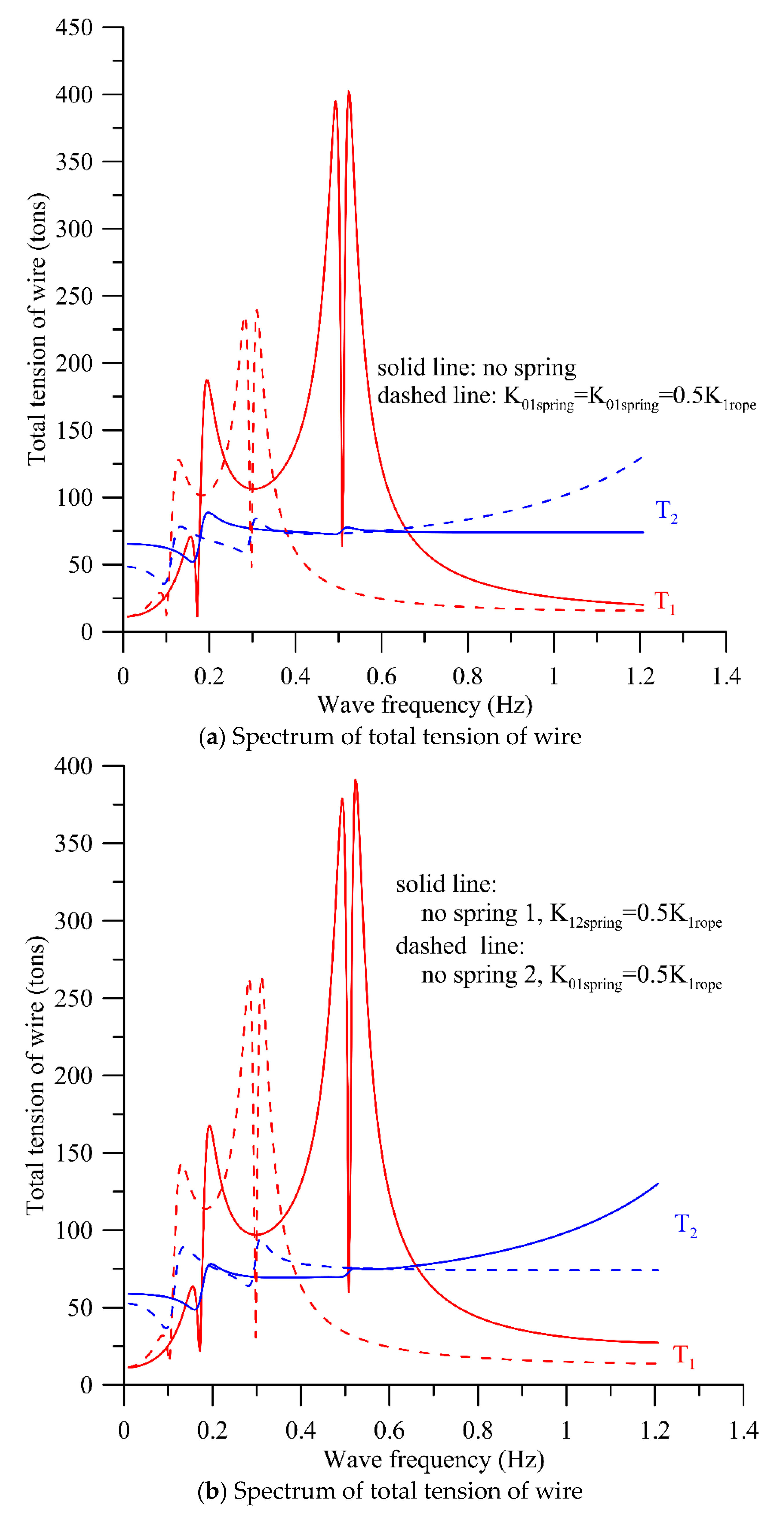
To save the cost of the rope, the rope angle becomes larger, or the large cross-sectional area of the pontoon is used for some reason. As discussed above, the dynamic tension of the rope will be too large. Here, we will study the effect of the buffer spring on reducing the dynamic response. Considering the parameters {θ
1 = 40°,
ABB = 7 m
2},
Figure 6 shows the dynamic displacements spectrum of the platform and the pontoon. It is found, from
Figure 6a, that the resonant frequencies of the system with two buffer springs,
, are lower than those without the buffer spring. The dynamic displacements of the former are greater than those of the latter. This is because the rigidity of the system with the buffer spring is smaller than that without the buffer spring. Further,
Figure 6b shows the dynamic displacements spectrum of two systems, (1) with buffer spring 2 only,
, and (2) with buffer spring 1 only,
. Comparing
Figure 6a,b, it is found that the dynamic displacements with the two buffer springs,
, are almost the same as those with buffer spring 1 only,
. Moreover, the dynamic displacements without the buffer springs are almost the same as those with buffer spring 2 only,
. Based on this fact, it is implied that the effect of buffer spring 1 is significant. However, the effect of buffer spring 2 is negligible. This fact is verified by
Figure 7 and
Figure 8. With the same parameters of
Figure 6,
Figure 7 demonstrates the dynamic tensions of ropes. The dynamic tensions of the two systems, (1) without the buffer springs and (2) with buffer spring 2 only,
, are almost the same and are very large. However, the dynamic tensions of the two systems, (1) with two buffer springs,
, and (2) with buffer spring 1 only,
, are almost the same and are very small. The same phenomenon for the total tensions of ropes is presented in
Figure 8.
According to the investigation report of the typhoon invading Taiwan from 1897 to 2019, in the Central Meteorological Bureau Library of Taiwan, the maximum offshore sea wave height of Taiwan’s Green Island during the 50-year regression period is about 12.6 m, the corresponding period is about 14.7 s. The wave spectrum is listed in
Table 3 [
29]. In this study, the wave height and wave frequency are assumed to be 20 m and 0~1.2 Hz, respectively, in all the cases for investigating the dynamic behaviors of the system. As a result, it is found that the maximum tension of ropes is significantly lower than the fracture strength of the high-strength PE Dyneema, which is 759 tons. It is theoretically proved that the protection method can avoid the damage of the floater platform and the mooring line, due to Typhoon wave impact.


