Technical Note

Heave Compensation Dynamics for Offshore Drilling Operation

1
School of Engineering and Computer Science, Washington State University, Vancouver, WA 98686, USA
2
Department of Naval Architecture and Ocean Engineering, Dong-Eui University, Busan 47340, Korea
*
Author to whom correspondence should be addressed.
J. Mar. Sci. Eng. 2021, 9(9), 965; https://doi.org/10.3390/jmse9090965
Submission received: 31 July 2021 / Revised: 18 August 2021 / Accepted: 22 August 2021 / Published: 6 September 2021
(This article belongs to the Special Issue Simulation Based Maritime Design)

Abstract

:
In this study, dynamic response analysis of a heave compensation system for offshore drilling operations was conducted based on multibody dynamics. The efficiency of the heave compensation system was computed using simulation techniques and virtually confirmed before being applied to drilling operations. The heave compensation system was installed on a semi-submersible and comprises several interconnected bodies with various joints. Therefore, a dynamics kernel based on multibody dynamics was developed to perform dynamic response analysis. The recursive Newton–Euler formulation was adopted to construct the equations of motion for the multibody system. Functions of the developed dynamics kernel were verified by comparing them with those from other studies. Hydrostatic force, linearized hydrodynamic force, and pneumatic and hydraulic control forces were considered the external forces acting on the platform of the semi-submersible rig and the heave compensation system. The dynamic simulation was performed for the heave compensation system of the semi-submersible rig for drilling operations up to 3600 m water depth. From the results of the simulation, the efficiency of the heave compensation system was evaluated to be approximately 96.7%.

1. Introduction

As the use of simulation tools to analyze mechanical systems has been increasing, the shipbuilding industry uses simulation techniques progressively when deploying various types of mechanical systems. For example, Figure 1a shows a goliath crane used to lift and transport heavy loads and essential facilities in shipyards. Figure 1b shows a floating crane, whose capacity is usually greater than that of the goliath crane. As shown in the figure, unlike the goliath crane, the floating crane is operated in the sea. Figure 1c shows an offshore drilling rig. All these facilities are mechanical systems that must be analyzed concerning their dynamic aspects for accurate and reliable design. Among these three examples, we focused on the offshore drilling rig in this study.
A drilling rig is a massive offshore facility and comprises two parts: a platform and an offshore drilling system installed on the platform, as shown in Figure 2. One of the main functions of the offshore drilling system is to drill a hole in the seabed, which requires several sub-systems, including a drill string composed of steel pipes and a drill bit to dig the hole, as well as a hoisting system to raise and lower the drill string in and out of the hole. However, the semi-submersible moves owing to the effect of waves. The horizontal motions of the semi-submersible can be controlled by its mooring and dynamic positioning system, in contrast to the vertical motion. Therefore, a heave compensation system is required to keep the drill string stationary and unaffected by the heave motion. However, the motion and efficiency of the heave compensation system need to be evaluated with dynamic response analysis before applying it in offshore drilling operations. In this study, we aimed to develop a multibody dynamics kernel to perform dynamic response analysis and control of the heave compensation system of an offshore drilling rig by simulating the drilling operations under various wave loads.

2. Related Works

2.1. Multibody Dynamics Kernels

Automatic dynamic analysis of mechanical systems (ADAMS) is a bundled software that comprises various integrated programs that aid engineers in performing three-dimensional kinematic and dynamic analyses of mechanical systems [1,2]. ADAMS generates equations of motion for multibody systems using augmented formulation. The users can define any multibody system comprising several rigid and flexible bodies interconnected by joints. ADAMS supplies various types of joints, such as fixed, revolute, and spherical. Various external forces can also be applied to the multibody systems; however, ADAMS cannot handle hydrostatic and hydrodynamic forces, which are the dominant forces exerted on the floating platform. Open dynamics engine (ODE) is an open-source library for simulating multibody dynamics [3]. Similar to ADAMS, ODE derives equations of motion for multibody systems using augmented formulation. However, ODE can treat only rigid bodies and not flexible ones. Moreover, ODE also cannot handle hydrostatic and hydrodynamic forces.
RecurDyn is a three-dimensional simulation software that combines dynamic response analysis and finite element analysis tools for multibody systems [4]. It is 2–20 times faster than other dynamic solutions due to its advanced fully recursive formulation. Simscape Multibody also supports multibody modeling. It is a module integrated in Matlab Simulink, and it is very convenient to use. However, although various joints and external forces can also be applied to the multibody systems, RecurDyn and Simscape cannot handle hydrostatic and hydrodynamic forces.
The hydrostatic force and hydrodynamic force can be calculated by considering the shape and motion of the semi-sub based on potential theory. For this calculation, it is usually necessary to use dedicated software, but it is not easy to integrate the software for with a commercial dynamics program. Therefore, we developed a dynamics kernel for the dynamic analysis of offshore structures such as a semi-submersible drilling rig or drillship. The equations of motion for multibody systems were derived using recursive formulation. Moreover, the external force calculation module can generate hydrostatic force by considering the nonlinear effects and linearized hydrodynamic force as external forces. Table 1 shows the features of the different dynamics kernels that were compared in this study.

2.2. Dynamic Response Analysis of a Heave Compensation System

There have been several studies related to heave compensation systems. As shown in Table 2, simulations of DSC were performed in all papers except Do’s [5]. However, most studies considered the heave compensation system as a mass spring–damper system or lumped mass system. Only Beutlich’s study modeled the DSC system as multibody system [6]. However, Beutlich’s study did not treat the hydrostatic force, and hydrodynamic force. Therefore, in this study, a multibody dynamics kernel was developed and used for the dynamic analysis of the system and the hydrostatic and hydrodynamic forces were considered as an external force.

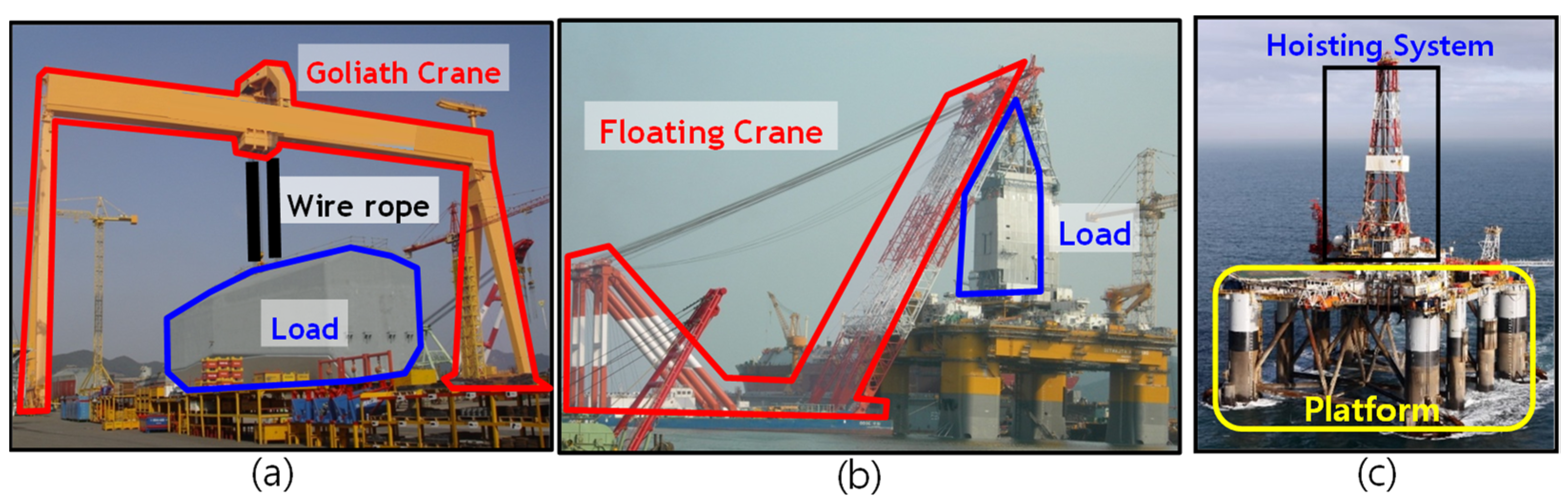
3. Heave Compensation System Equipment

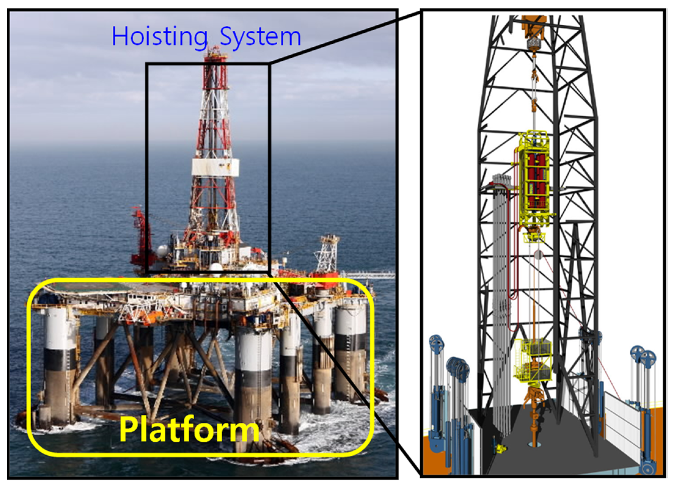
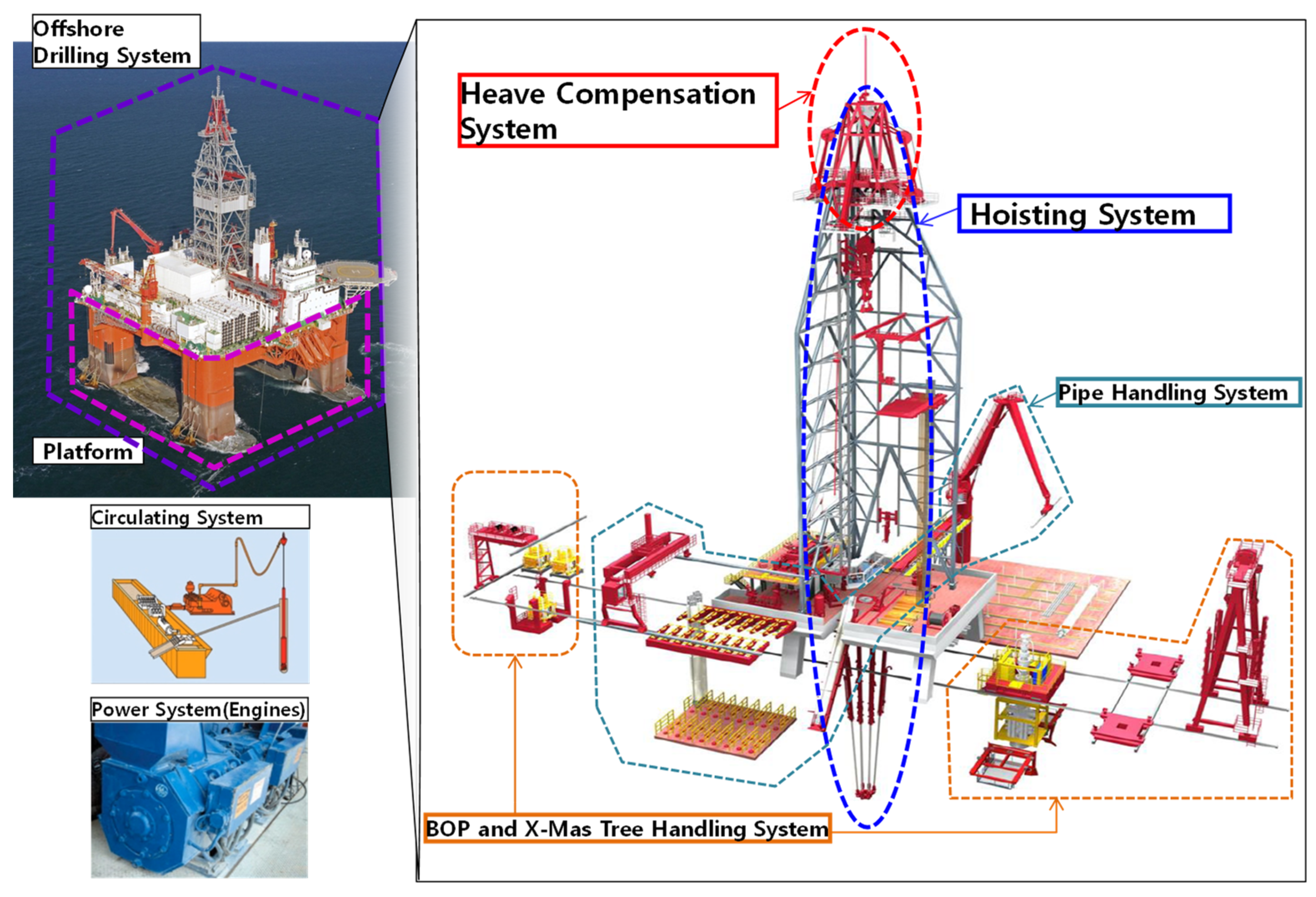
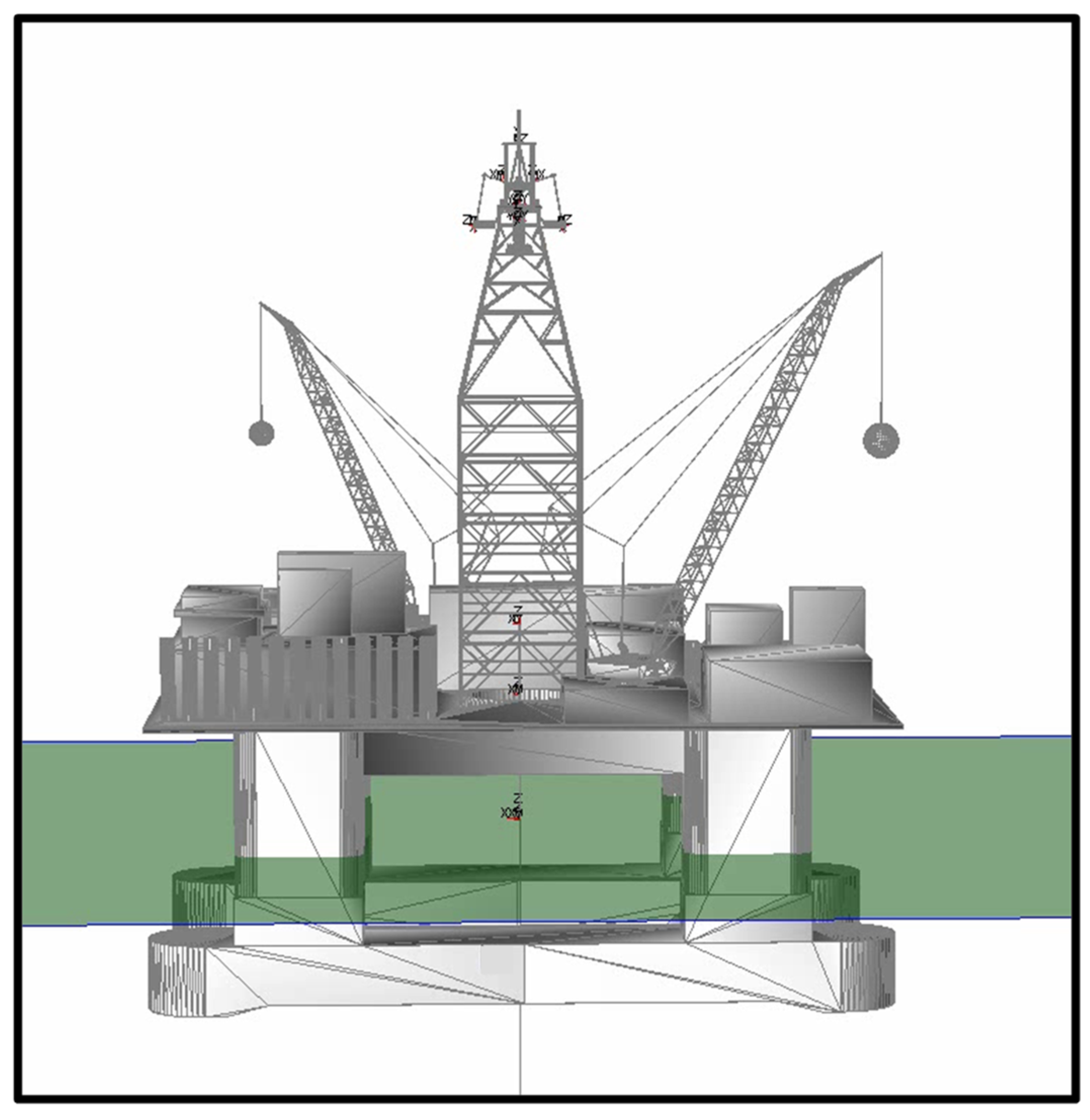
3.1. Configuration of an Offshore Drilling System

The primary function of the offshore drilling system of the offshore drilling rig is to drill a hole in the seabed, which requires multiple pieces of equipment. The equipment systems used in drilling a hole include six main categories: the hoisting system, heave compensation system, pipe handling system, BOP and X-mas tree handling system, circulation system, and power system, as shown in Figure 3.
Among these main categories, we focused on the heave compensation system in this study. In the following subsection, the heave compensation system is explained in detail [10].

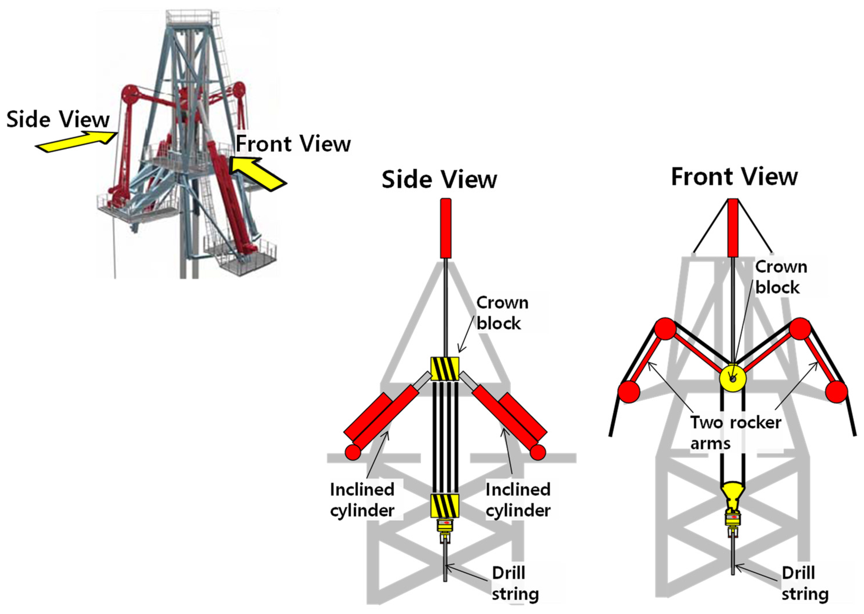
3.2. Components of a Heave Compensation System

The heave compensation system is composed of a drill string compensator (DSC) and an active heave compensator (AHC), as shown in Figure 4.
The DSC is a passive heave compensator, mounted on top of the hoisting system, to minimize the effects of the drill rig heave on the drill string. In this paper, we modeled and analyzed “drill string compensator” from “Aker solutions”. The DSC supports the weight of the drill string, which comprises 1200-m steel pipes and a drill bit.
As pneumatic and hydraulic systems are capable of transmitting a large amount of power, the DSC employs a combined pneumatic and hydraulic system that acts as a low-ware spring using air pressure, which is controlled to vary the load.
The side and front views of the DSC are shown in Figure 5. The side view shows two inclined cylinders that support the crown block connected to the drill string. The DSC also has two mounted rocker arms to support four-wire sheaves.
The compensator and the suspended load, including the crown block and the drill string, may be considered a spring-mass system. At this moment, the DSC can be regarded as a pneumatic spring. This is achieved by suspending the crown block from a large piston in the cylinder connected to a high-pressure air pressure vessel (APV). The volume of the air can be increased or decreased to alter the spring rate. Moreover, the mean pressure of the air is controlled to vary the load that can be supported [6].
As shown in Figure 6a,b, using inclined cylinders, the force in the direction of the cylinders changes depending on the heave. Furthermore, as shown in Figure 6c,d, the rocker arms allow a full stroke of the compensator with a constant length of the wireline within the system. The rocker arm sheaves are equipped with a wire guide to prevent wire derailing. Therefore, the DSC provides stable positions for the crown block and the drill string in reference to the seabed.
However, because of the DSC seal friction between the inner wall and the cylinder’s piston, which tends to enforce the heave disturbance, an AHC is additionally required to overcome the disturbance. However, in ideal conditions, the DSC can support most of the loads. The efficiency of the heave compensation system is more than 95% for any ship motion.
The explained heave compensation system is a collection of rigid bodies interconnected with various joints that limit the relative motion of pairs of bodies. It can be considered a multibody system. Because the mechanism of the heave compensation system is not simple, their body connections should be modeled precisely for accurate simulation. Therefore, a multibody dynamics kernel was developed in this study for the dynamic analysis of the system.

4. Multibody Dynamics Based on Recursive Formulation

In this section, we describe the developed multibody dynamics kernel based on recursive formulation.

4.1. Forward and Inverse Dynamics

The dynamics of a rigid-body system can be described by the equations of motion, which specify the relationship between the forces acting on the system and the accelerations produced. In this section, we focus on the algorithms for the following two particular calculations.
-
Forward dynamics: The calculation of the acceleration response of a given rigid-body system to a given applied force;
-
Inverse dynamics: The calculation of the force that must be applied to a given rigid-body system to produce a given acceleration response.
Both forward and inverse dynamics are implemented using recursive formulas for the simulation [11]. The equations of motion for each body of the multibody system based on recursive formula can be summarized as below.
v ^ = i i X i 1 · v ^ i 1 + S i · q ˙ i
a ^ i = i i X i 1 · a ^ i 1 + S i · q ¨ i + S ˙ i · q ˙ i + v i ^ × S i · q i ˙
f ^ i B = I i ^ · a ^ i 1 + v ^ i 1 × I ^ i · v ^ i
f ^ i = f ^ i B + i i X i + 1 · f ^ i + 1 f ^ i e x t
τ i = S i T · f ^ i
where:
v ^ i : Velocity vector of body i (six components);
a ^ i : Acceleration vector of body i (six components);
q i : Generalized coordinate (joint values);
S i : Velocity transformation matrix;
I i : Mass and mass moment of inertia of body i;
f ^ i B : Resultant force exerted on body i;
f ^ i e x t : External force exerted on body i;
f ^ i : Force across the joint i;
τ i : Force generated by joint i (generalized force);
i i X i 1 : Coordinate transformation matrix.
In inverse dynamics, as the positions q i , velocities q ˙ i , and accelerations q ¨ i of generalized coordinates are provided, the velocities v ^ i and accelerations a ^ i of each body can be computed. Furthermore, the forces f ^ i and the generalized forces τ i , which are exerted on each link, can also be computed in a recursive fashion [11,12].
Equations (1)–(5) can be rearranged into Equations (6)–(9), which are the equations of motion for the forward dynamics of the multibody system based on recursive formulation.
a ^ i = i i X i 1 · a ^ i 1 + S i · q ¨ i + c i
q ¨ i = ( S i T I ^ i A S i ) 1 ( τ i S i T ( I i A ( i i X i 1 a ^ i 1 + c i ) + p i A ) )
I ^ i A = I ^ i + X i + 1 · I ^ i + 1 A · i i + 1 X i i i X i + 1 · I ^ i + 1 A · S i + 1 · ( S i + 1 T I ^ i + 1 A S i + 1 ) 1 S i + 1 T I ^ i + 1 A i i + 1 X i
p i A = p i + i i X i + 1 · p i + 1 A + i i X i + 1 · I ^ i + 1 A · c i + 1 + i i X i + 1 · I ^ i + 1 A · S i + 1 · ( S i + 1 T I ^ i + 1 A S i + 1 ) 1 ( τ i + 1 S i + 1 T ( I i + 1 A c i + 1 p i + 1 A ) )
where:
c i = S ˙ i · q ˙ i + v ^ i × S i · q ˙ i
p i = v ^ i × I i · v ^ i f ^ i e x t
The multibody dynamics kernel was developed based on the equations of motion for the forward and inverse dynamics. Equations (6)–(11) are used to calculate the acceleration of the multibody when an external force is applied. Numerical integration was performed to calculate position and velocity by integrating acceleration, and the RK4 (Runge–Kutta fourth order) method was used for it.

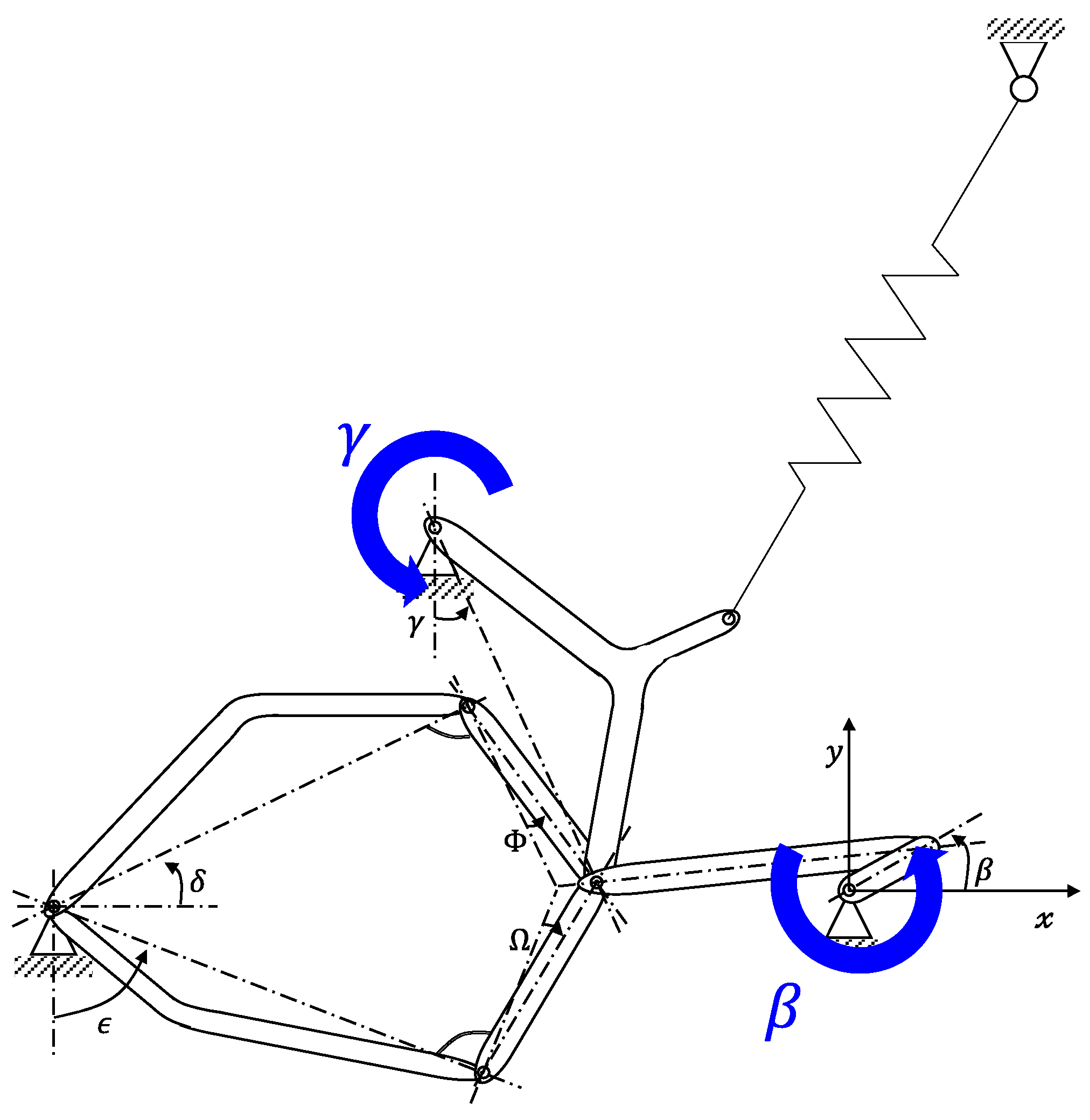
4.2. Verification of the Dynamics Kernel

We used a test model to verify the developed dynamics kernel with the dynamic codes developed in the 1980s. As shown in Figure 7, the test model was a multibody system comprising eight bodies and ten revolute joints. Additionally, the system had three closed loops.
The position, velocity, and acceleration of the generalized coordinates β and γ illustrated in Figure 8 were compared with those obtained from [2]. As shown in Figure 8, our simulation results matched highly with the reference data, and it shows the same level of calculation performance as the module developed in other papers.

5. Construction of Mathematical Model

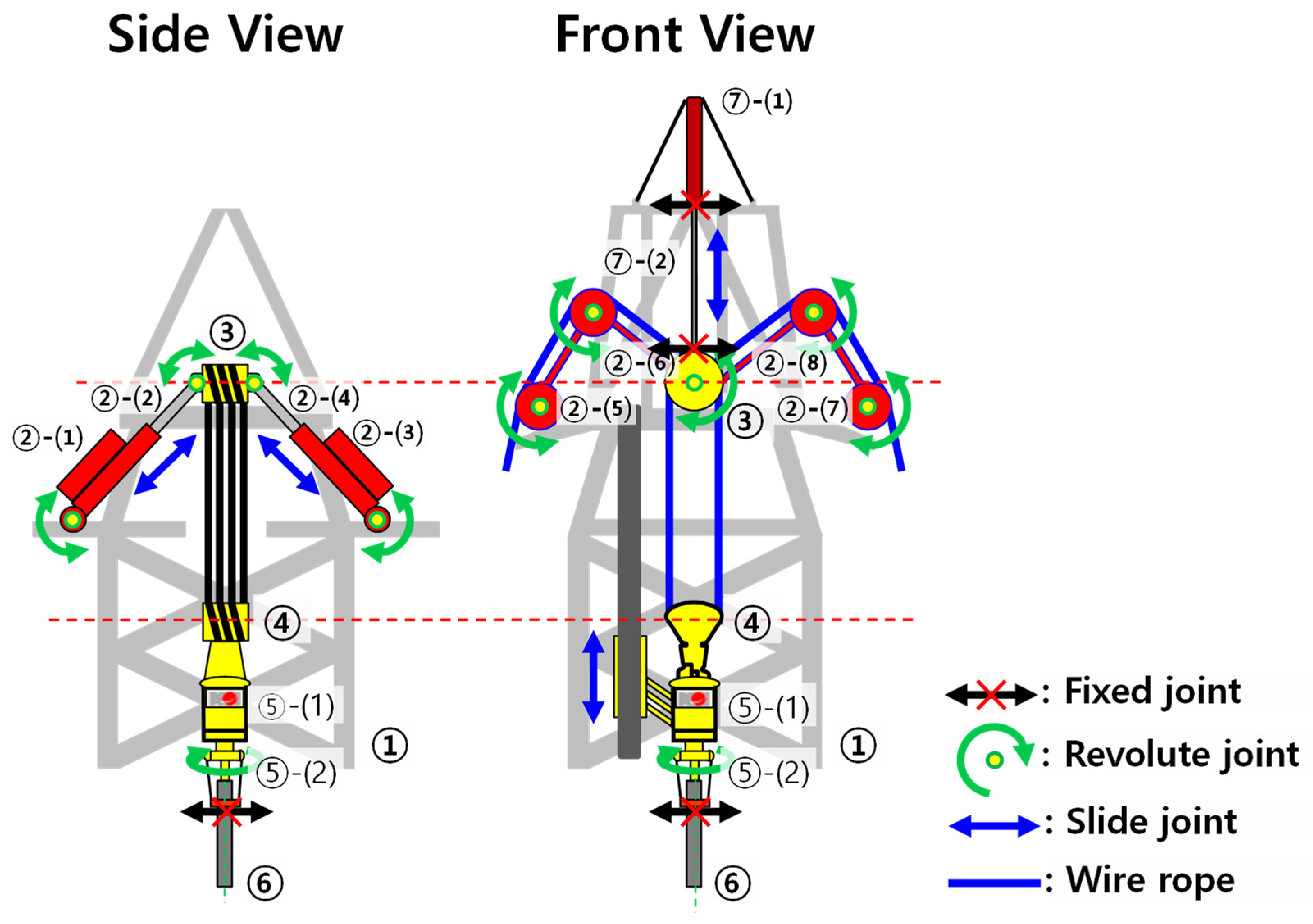
5.1. Mechanical Configuration of the Hoisting and Compensation System

The mechanical configuration of the hoisting and heave compensation system comprises bodies and joints. The bodies are considered rigid bodies that are interconnected with several types of joints. The types of joints that are used to construct the hoisting and heave compensation system are as follows.
-
Fixed joint: A joint that can fix one body to another; this joint has a zero degree of freedom;
-
Revolute joint: A joint that can rotate around one axis; this joint has one degree of freedom;
-
Slide joint: A joint that can translate along one axis; this joint has one degree of freedom.
Figure 9 shows the ② DSC, ⑤ top drive, and ⑦ AHC in detail. The DSC comprises eight bodies, and the top drive and AHC comprise two bodies each.
The DSC contains two cylinders (②-(1)~(4)) and two rocker arms (②-(5)~(8)). In the side view shown in Figure 9, the cylindrical tubes ②-(1) and ②-(3) are connected to the ② drilling structure (derrick) with revolute joints and the cylindrical rods (②-(2) and ②-(4)) with slide joints. The ends of the cylindrical rods are connected to the ③ crown block with revolute joints. The front view shows that the two rocker arms contain two links each. The bottom ends of the links (②-(5) and ②-(7)) are connected to the ① derrick with revolute joints, and the other ends are connected to links ②-(6) and ②-(8) with revolute joints. Links ②-(6) and ②-(8) are also connected to the ③ crown block with revolute joints.
The tube of the AHC ⑦-(1) is connected to the derrick with a fixed joint and to the rod ⑦-(2) with a slide joint. The other end of the rod ⑦-(2) is connected to the crown block with a fixed joint.

5.2. Pneumatic and Hydraulic Control of the Heave Compensator

The heave compensation system uses pneumatic and hydraulic systems, which are suitable for transmitting a large amount of power over great distances.
The DSC is a combined pneumatic and hydraulic system that acts as a low-rate spring using air pressure, which is controlled to vary the load that can be supported. Therefore, it is called a passive heave compensator. The DSC mainly comprises the cylinder, accumulator, and APV. The AHC is the hydraulic system that is used to compensate for the seal friction of the DSC to maintain the stationary position of the crown block. In this study, we focused on the effect of the volume of the APV, which is one of the DSC components [13].
For the pneumatic and hydraulic control model design, the research of McNary [14] was referred to. This research shows that the normal schematic of the pneumatic and hydraulic control model consists of APVs, accumulators, cylinders, drain, isolation valves, ventilation valves, etc.
However, we simplified the schematic diagram as shown in Figure 10, because the essential components are the APVs, accumulators, and cylinders in the pneumatic and hydraulic control model.
In Figure 10, p G and p L are the pressure values of the gas and oil, respectively, V G is the volume of the gas, A C is the area of the piston, y C is the position of the crown block, and y p is the piston’s position. As the crown block pushes the cylinder piston downwards, the air volume reduces, and pressure increases until the increase in the pressure balances the load. Conversely, as the piston moves upwards, the total volume increases, effectively reducing the pressure until the decrease in the pressure balances the load. In any continuous compression process, the relationship between the absolute gas pressure p G and the gas volume V G is expressed by the following equation using the polytropic coefficient n.
p G · V G n = C o n s t .
F D S C = A C · p G
By using these two equations, the equation for calculating pneumatic force can be derived as follows.
F D S C = A C · p G , 0 · ( V G , 0 V G , 0 + A C · ( y C y p ) ) n
For the initial values of the gas volume and pressure p G , 0 and V G , 0 , the data of the DSC from Daewoo Shipbuilding & Marine Engineering is referred to [15].

5.3. Construction of Equations of Motion for the Heave Compensation System

As explained in the previous section, the heave compensation system comprises many mechanical parts such as inclined cylinders and rocker arms, interconnected by various types of joints, as shown in Figure 11.
In this study, the heave compensation system was modeled as 11 rigid bodies and 15 joints. Therefore, after including the semi-submersible and the hoisting tower, the so-called “derrick” the whole system was modeled as 13 rigid bodies and 17 joints. The drill string was modeled assuming a 12,000-m drill pipe, 200-m heavily walled drill pipe, and 100-m drill collar [16].
For simulating the external forces, the hydrostatic force, hydrodynamic force, and control force were considered. In contrast with the commercially available dynamics kernels, the kernel developed in this study can handle both hydrostatic and hydrodynamic forces. The hydrostatic force of the semi-submersible was calculated by considering an instantaneous position and orientation. The linearized hydrodynamic force was converted from the frequency domain to the time domain with convolution integral. The “added mass” and “damping coefficient” of semi-submersible in the frequency domain were calculated using WADAM, a commercial software [17].

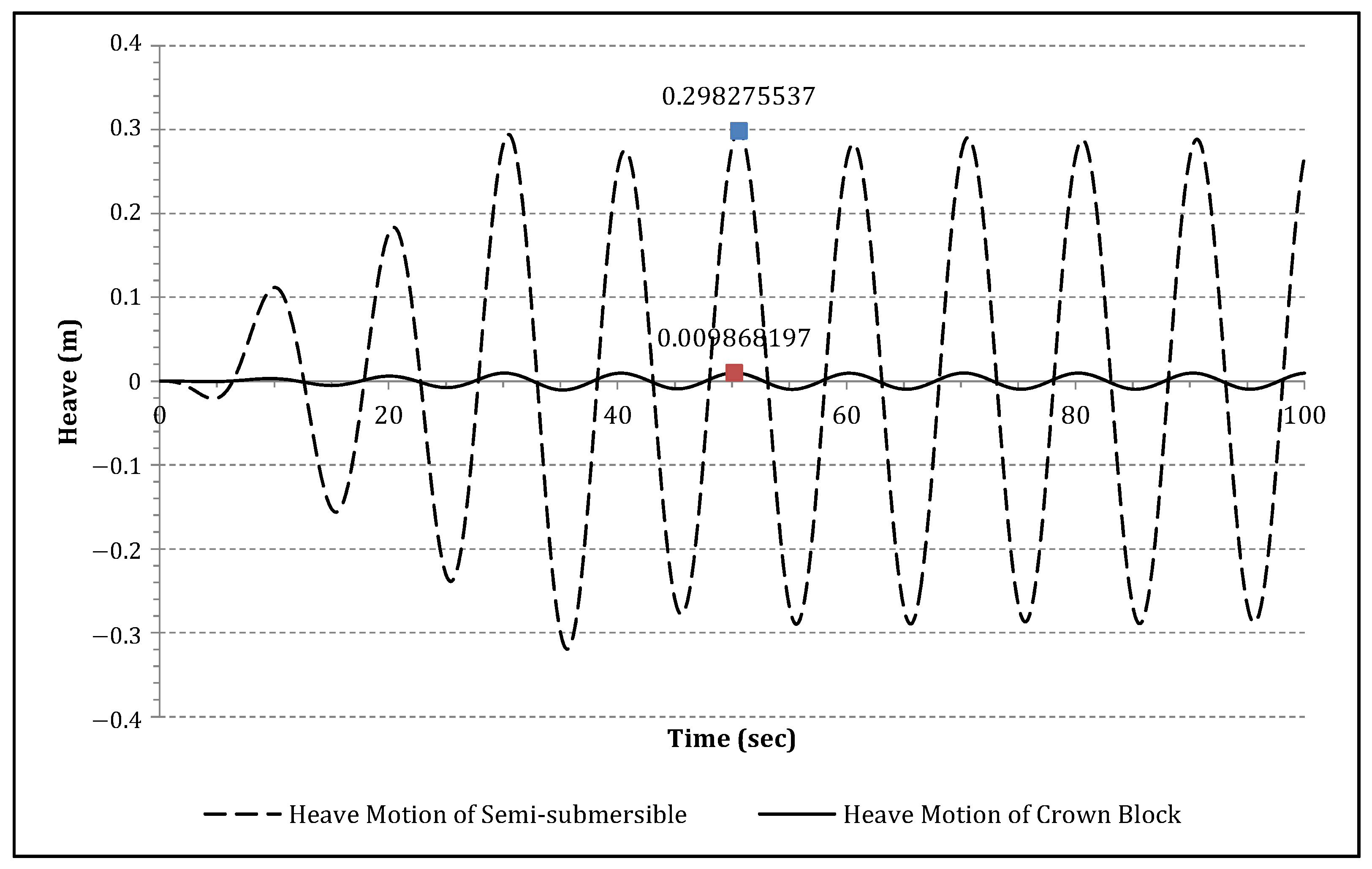
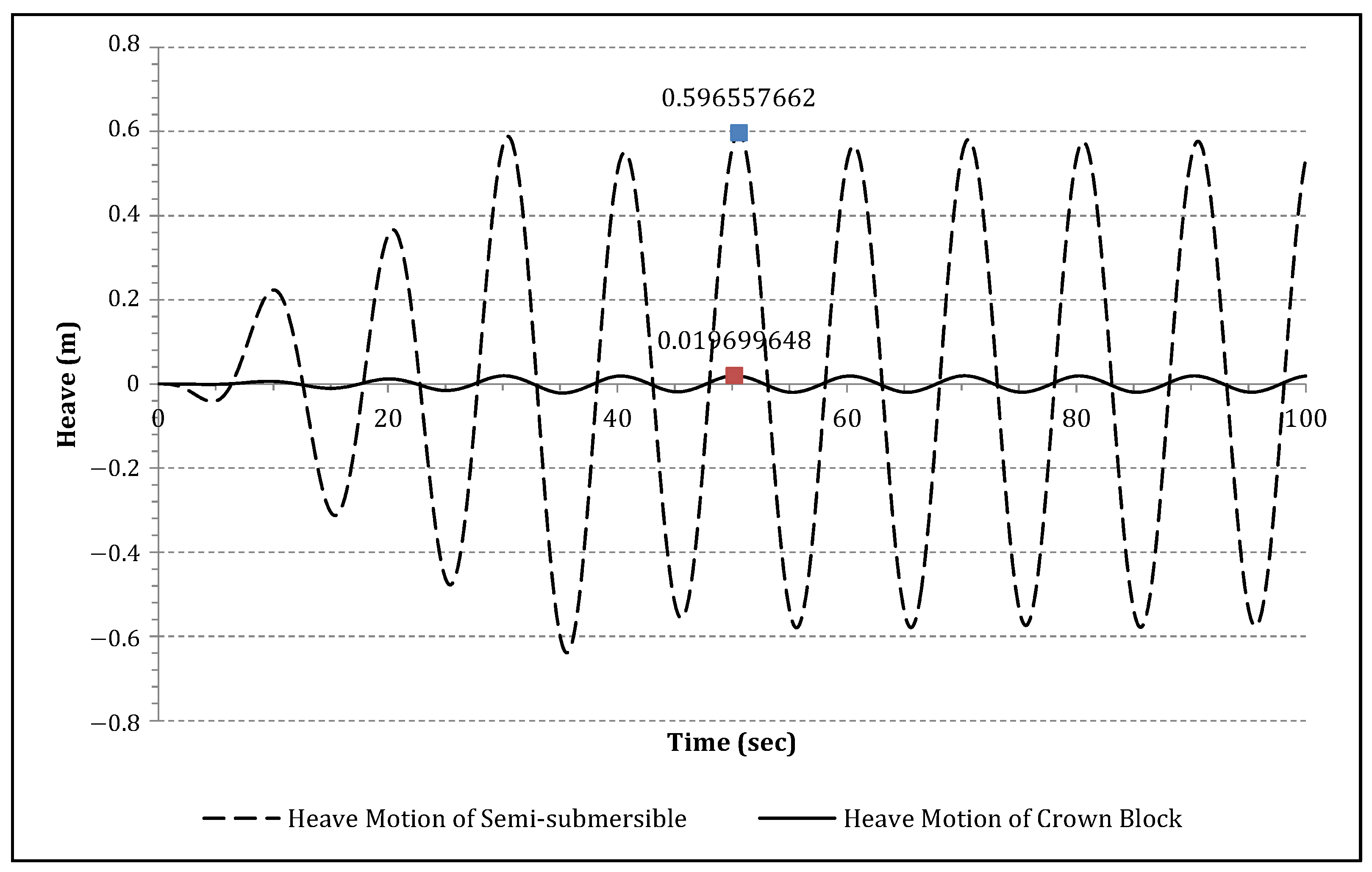
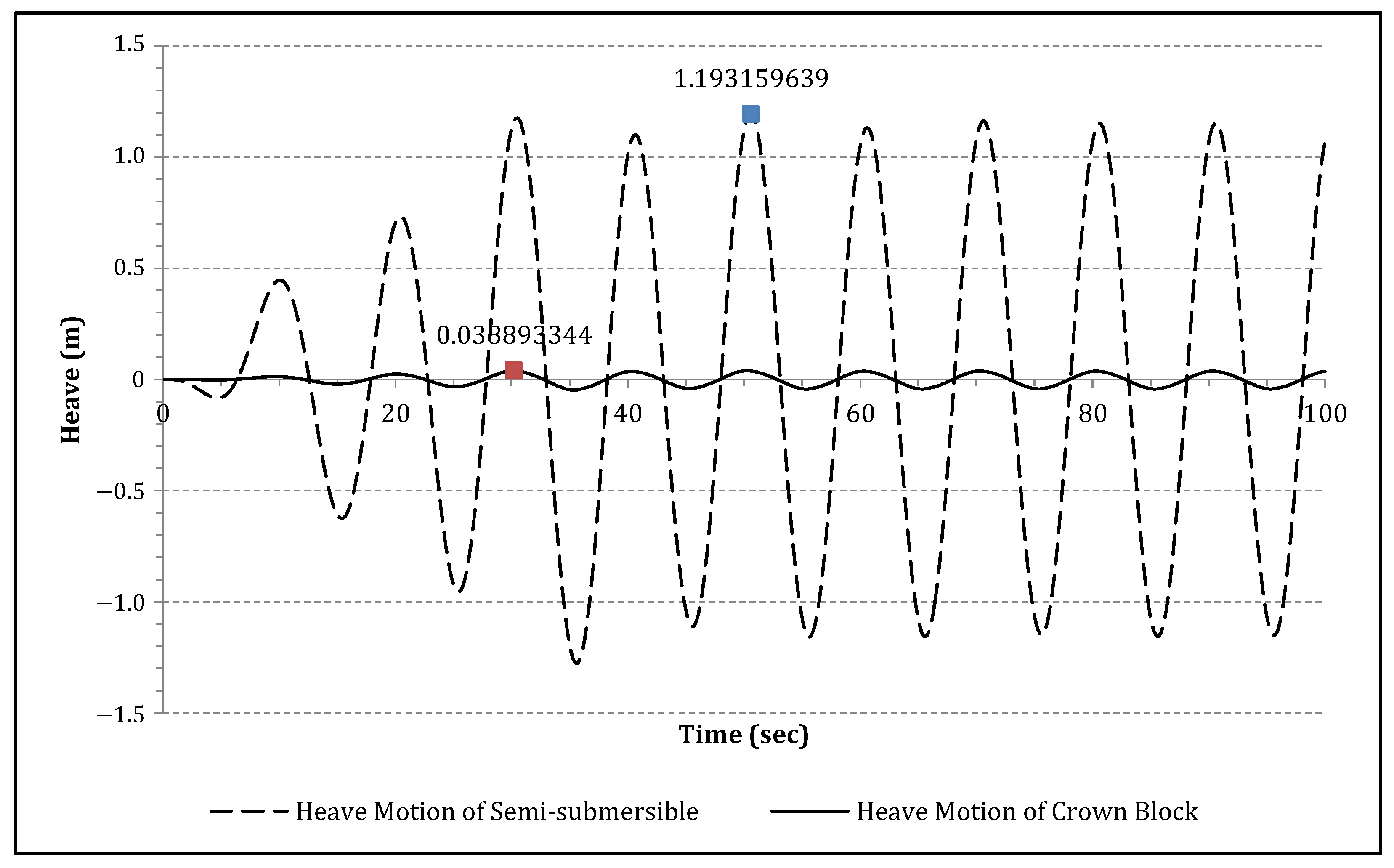
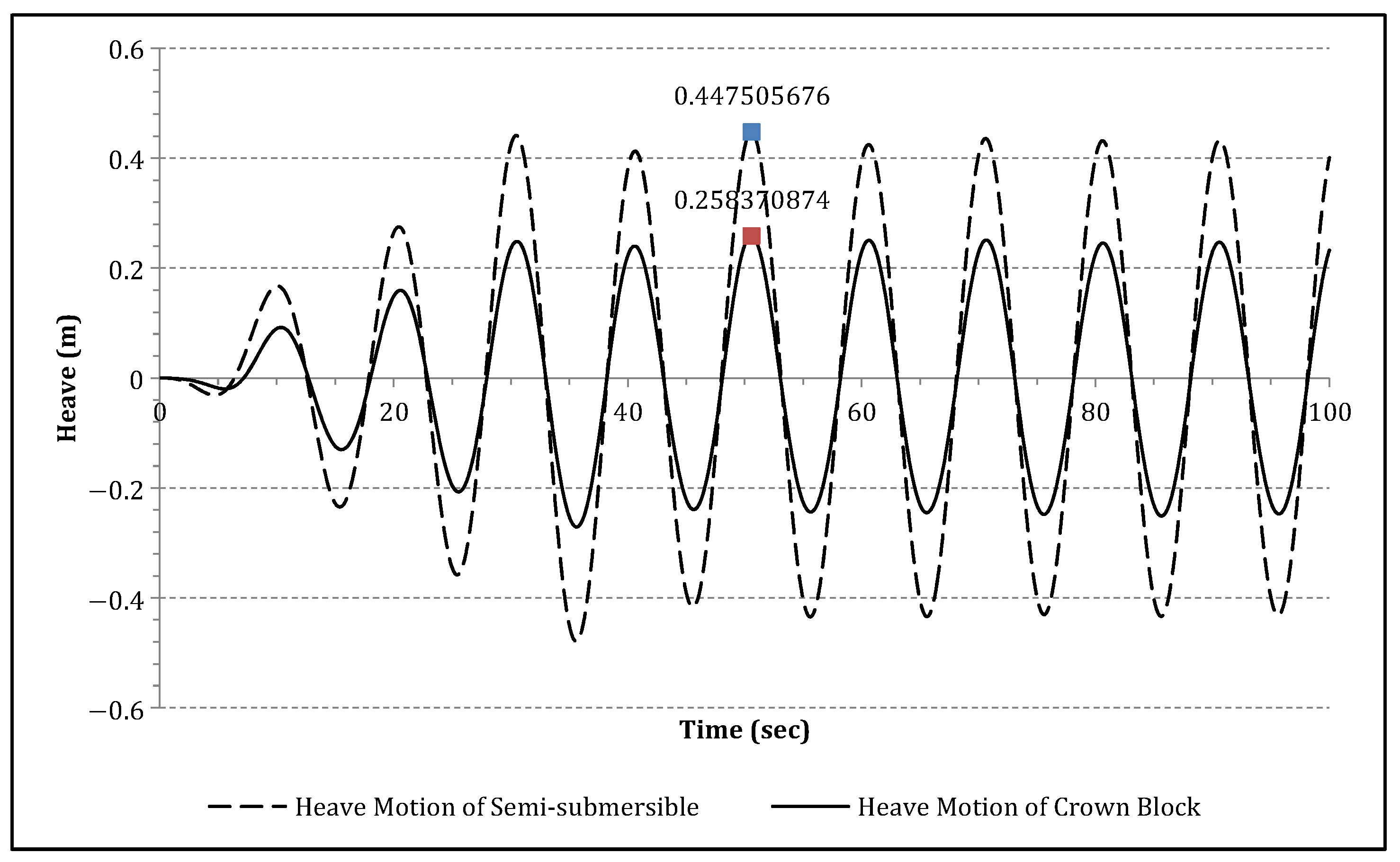
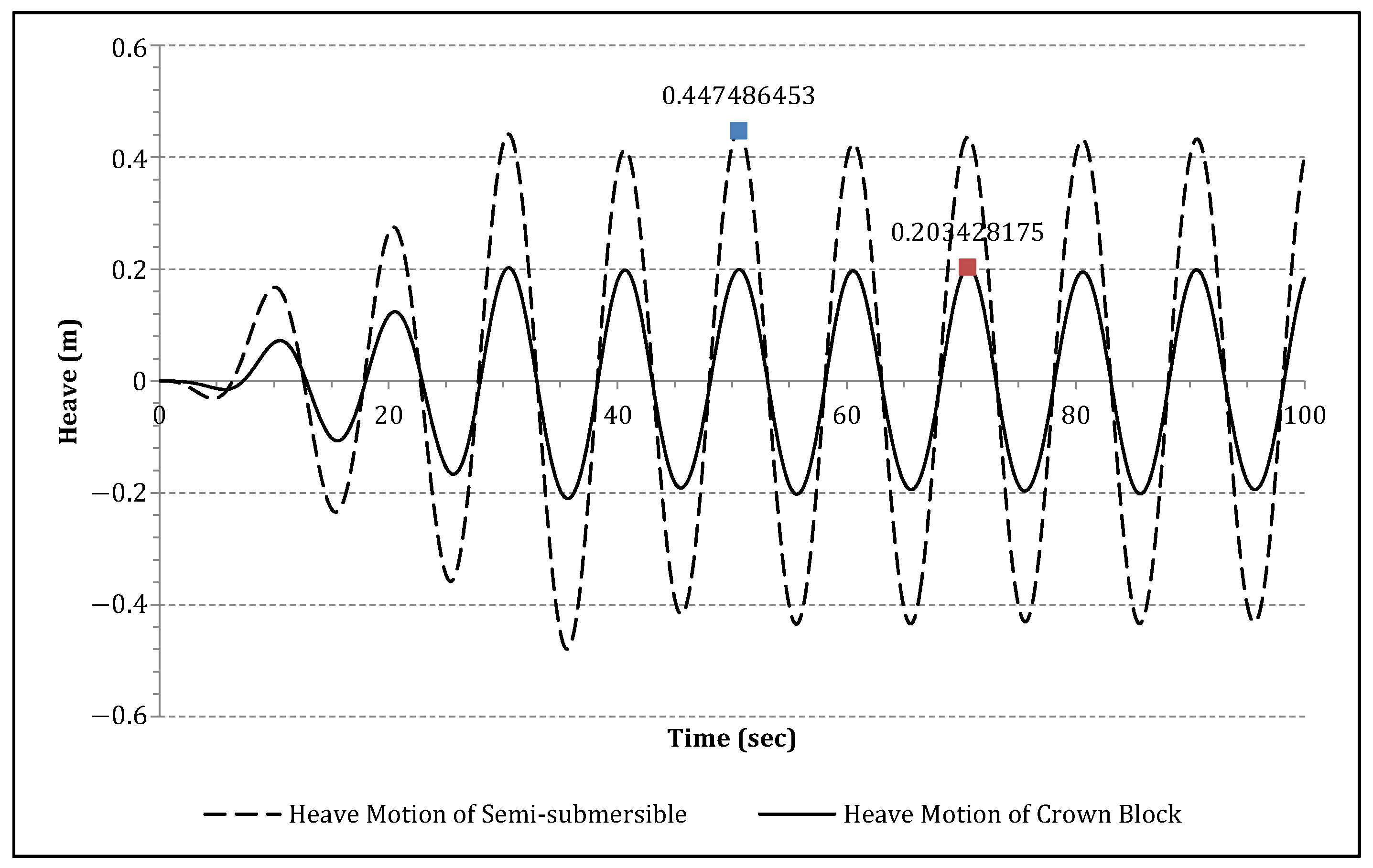
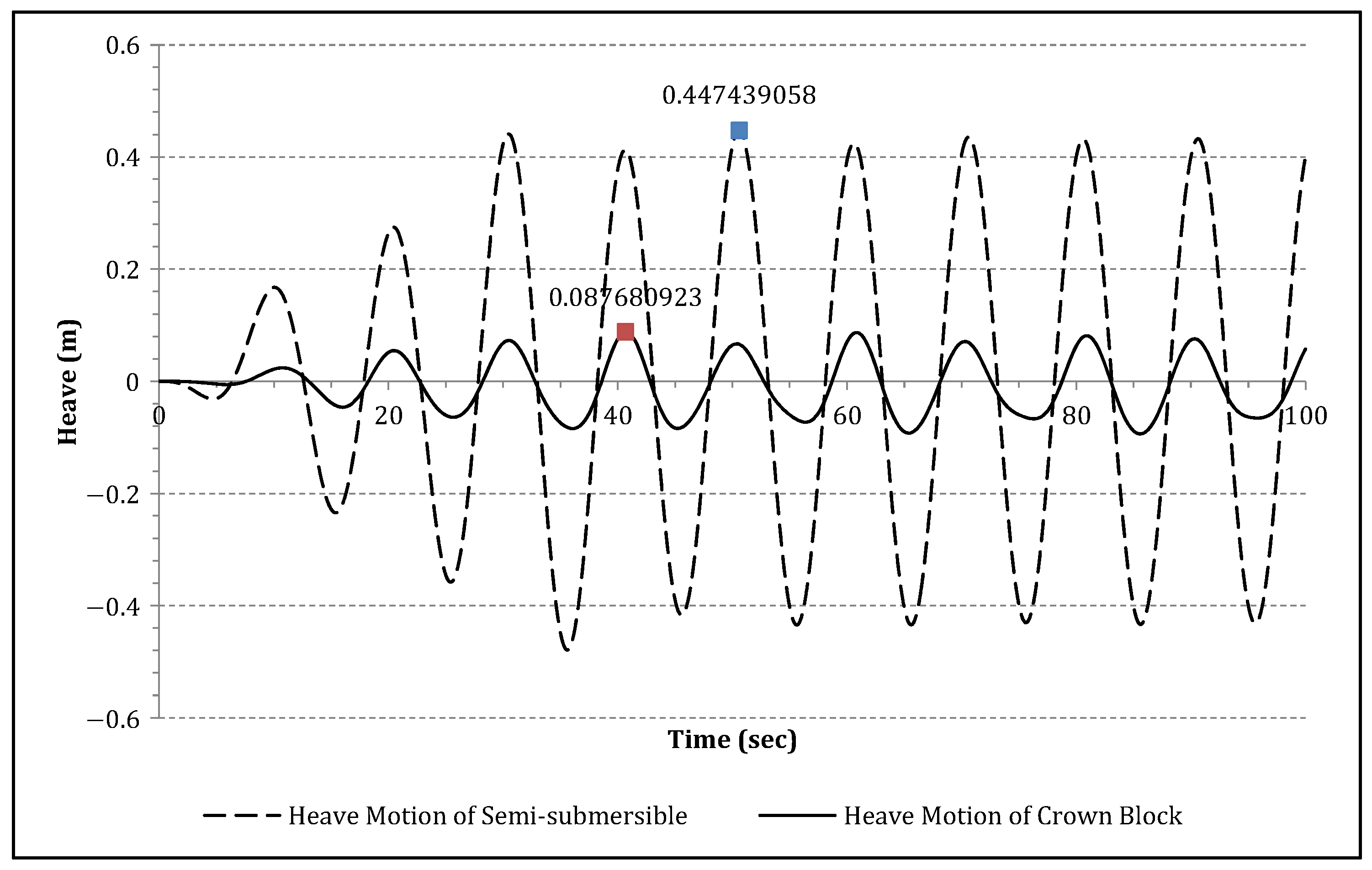
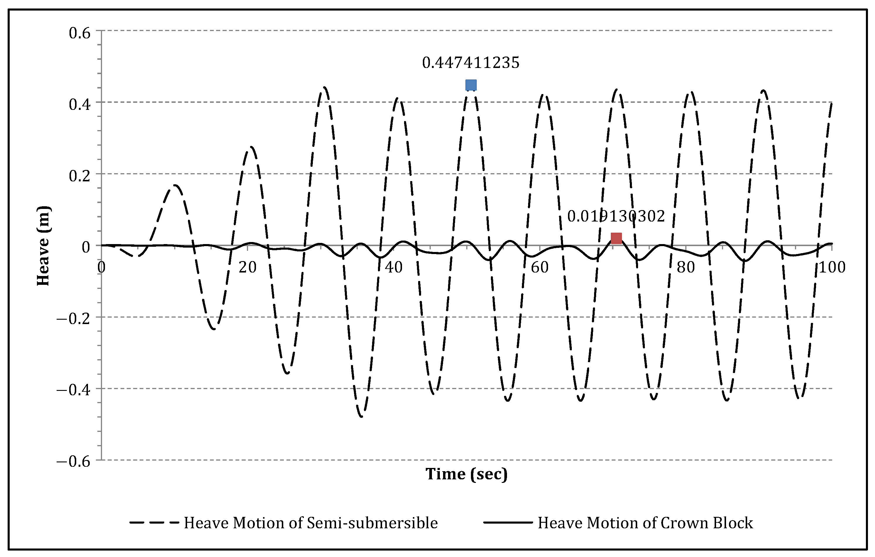
6. Dynamic Analysis of the Heave Compensation System

For the numerical simulation, the horizontal motions were assumed to be controlled by the mooring and dynamic positioning system. In addition, a set of waves with an amplitude of 4 m, a period of 10 s, and a wavelength of 156 m was applied. Figure 12 shows the results of the geometrical modeling.
Figure 13, Figure 14, Figure 15 and Figure 16 show the dynamic responses of the semi-submersible and crown block. The simulation results show that the amplitude of the heave motion of the crown block is between 0.0049 and 0.0389 m, and that of the semi-submersible is between 0.1491 and 1.1931 m. Thus, the efficiency of the heave compensation system was approximately 96.7%, which is similar to the 95% performance efficiency generally observed for these compensation systems.
After developing the simulation system, a parametric study was also performed, and the results can be utilized to design the pneumatic system of the heave compensation system. For the parametric study, waves with a period of 10 s, a wavelength of 156 m, and an amplitude of 3 m were applied for varying volumes of the APV. The results of the simulation are as follows. In Figure 21, since the force exerted by the heave compensation system and gravity are almost in equilibrium, irregular motion independent of the semi-sub periodic motion was observed.
The efficiency of the DSC is the ratio of the maximum amplitude of the semi-sub to the maximum amplitude of the crown block measured in Figure 17, Figure 18, Figure 19, Figure 20 and Figure 21. As shown in Figure 22, 1.0 of APV volume was provided initially from the shipyard itself.
The larger the APV volume, the higher is the efficiency of the DSC. When the volume reaches V G , 0 × 1.8 L, the state of the crown block becomes neutral and its restoring force disappears, so it can be considered dangerous. From the above results, we can confirm that the results of the simulation based on multibody dynamics can be utilized for determining the limit and optimum value of the APV volume.

7. Conclusions

In this study, dynamic response analysis and control of a simulated hoisting and heave compensation system used on an offshore drilling rig during drilling operations was performed under various wave loads. For modeling the heave compensation system, a multibody dynamics kernel was developed, and pneumatic force was implemented for the DSC. According to the simulation results, the amplitude of the heave motion of the crown block was between 0.0049 and 0.0389 m, and that of the semi-submersible was between 0.1491 and 1.1931 m, which means that the efficiency of the heave compensation system was approximately 96.7%. A parametric study was also conducted using the developed simulation techniques, and the results of the simulation can be utilized for determining the limit and optimum value of the volume of the APV.

Author Contributions

Conceptualization, N.K.; supervision, D.K.; methodology, N.K.; investigation, N.K.; writing, N.K. and D.K. All authors have read and agreed to the published version of the manuscript.

Funding

This study was supported by the National Research Foundation of Korea (NRF) grant funded by the Korea government (MSIT) (No. NRF-2020R1G1A1014243).

Institutional Review Board Statement

Not applicable.

Informed Consent Statement

Not applicable.

Data Availability Statement

Not applicable.

Conflicts of Interest

The authors declare no conflict of interest.

References

  1. Orlandea, N.; Chace, M.; Calahan, D.A. A sparsity-oriented approach to the dynamic analysis and design of mechanical systems-part1&2. J. Eng. Ind. Trans. ASME 1977, 99, 773–779. [Google Scholar]
  2. Schiehlen, W. Multibody Systems Handbook; Springer: Berlin/Heidelberg, Germany, 1990; pp. 361–402. [Google Scholar]
  3. Smith, R. Open Dynamics Engine v0.5 User Guide. 2006, pp. 15–20. Available online: http://ode.org/ode-latest-userguide.pdf (accessed on 10 August 2021).
  4. FunctionBay, Inc. RecurDyn V7R5 Release Notes. 2011. Available online: https://pdfslide.net/documents/recurdyn-v7r5-release-notes-v-v-recurdyncatia-read-write-v-v-all-data-number.html (accessed on 10 August 2021).
  5. Do, K.; Pan, J. Nonlinear control of an active heave compensation system. Ocean. Eng. 2008, 35, 558–571. [Google Scholar] [CrossRef] [Green Version]
  6. Beutlich, T.; Lien, R. Multidisciplinary simulation of active heave compensators for offshore module handling systems. In Proceedings of the MULTIBODY Dynamics 2009: ECCOMAS Thematic Conference, Warsaw, Poland, 29 June–2 July 2009. [Google Scholar]
  7. Albers, P. Motion Control in Offshore and Dredging; Springer: Berlin/Heidelberg, Germany, 2010. [Google Scholar]
  8. Hatleskog, J.; Dunnign, M. Peer-reviewed technical communication—Passive compensator load variation for deep-water drilling. J. Ocean. Eng. 2007, 32, 3. [Google Scholar] [CrossRef]
  9. Lumeng, H.; Yanting, Z.; Lei, Z.; Meiying, L. Semi-active drilling drawworks heave compensation system. Pet. Explor. Dev. 2013, 40, 5. [Google Scholar]
  10. Bommer, P. A Primer of Oilwell Drilling; The University of Texas at Austin: Austin, UT, USA, 2008. [Google Scholar]
  11. Featherstone, R. Rigid Body Dynamics; Springer: Berlin/Heidelberg, Germany, 2008. [Google Scholar]
  12. Luh, J. On-line computational scheme for mechanical manipulators. J. Dyn. Syst. Meas. Control 1980, 102, 69–76. [Google Scholar] [CrossRef]
  13. Graber, K.; Pollard, E.; Jonasson, B.; Schulte, E. Overview of ocean drilling program engineering tools and hardware. Tech. Notes 2002, 31. Available online: https://www.semanticscholar.org/paper/Overview-of-Ocean-Drilling-Program-Engineering-and-Graber-Pollard/701cf277855b5af0e5717159e6060e3b05ffdb33 (accessed on 1 August 2021). [CrossRef]
  14. McNary, J.; Person, A.; Ozudogru, Y. A 7500-ton-capacity, shipboard, completely gimbaled and heave-compensated platform. J. Pet. Technol. 1977, 29, 439–448. [Google Scholar] [CrossRef]
  15. Daewoo Shipbuilding & Marine Engineering (DSME) Co. Ltd. Dynamic Response Analysis and Control of Hoisting System for Drilling Rig in Ocean Environment based on Multibody Dynamics; Technical Research Report; Central Research Institute: Kasauli, India, 2012. [Google Scholar]
  16. Jonggeun, C.; Schubert, J.; Juvkam-wold, H. Analyses and procedures for kick detection in subsea mudlift drilling. SPE Drill. Complet. 2007, 22, 296–303. [Google Scholar]
  17. Jo, A.; Ku, N.; Park, K.; Lee, K. Mathematical modeling and dynamic behavior analysis of drill string compensator for off-shore drilling operation. In Proceedings of the Society of Naval Architecture of Korea Fall Conference, Changwon, Korea, 20–25 October 2011. [Google Scholar]
Figure 1. Various types of mechanical systems in the shipbuilding industry; (a) goliath crane; (b) floating crane; and (c) offshore drilling rig.
Jmse 09 00965 g001
Figure 2. Offshore drilling rig and hoisting system.
Jmse 09 00965 g002
Figure 3. Six main categories of equipment systems on an offshore drilling system.
Jmse 09 00965 g003
Figure 4. Components of a heave compensation system.
Jmse 09 00965 g004
Figure 5. Side and front views of the drill string compensator.
Jmse 09 00965 g005
Figure 6. The operating mechanism of the drill string compensator.
Jmse 09 00965 g006
Figure 7. Generalized coordinates β and γ of the multibody system.
Jmse 09 00965 g007
Figure 8. Simulation results of the position and velocity of the generalized coordinates β and γ compared with those obtained from reference.
Jmse 09 00965 g008
Figure 9. Mechanical configuration of the heave compensation system.
Jmse 09 00965 g009
Figure 10. Simplified pneumatic and hydraulic control model.
Jmse 09 00965 g010
Figure 11. Joints and coordinate systems of heave compensation system.
Jmse 09 00965 g011
Figure 12. Visualization of the dynamic response of the heave compensation system.
Jmse 09 00965 g012
Figure 13. Dynamic response analyses of the semi-submersible and crown block with the heave compensation system for a 1-m wave amplitude.
Jmse 09 00965 g013
Figure 14. Dynamic response analyses of the semi-submersible and crown block with the heave compensation system for a 2-m wave amplitude.
Jmse 09 00965 g014
Figure 15. Dynamic response analyses of the semi-submersible and crown block with the heave compensation system for a 4-m wave amplitude.
Jmse 09 00965 g015
Figure 16. Dynamic response analyses of the semi-submersible and crown block with the heave compensation system for an 8-m wave amplitude.
Jmse 09 00965 g016
Figure 17. Heave motions of the semi-submersible and crown block for a 16.550 × 1.0-m3 APV.
Jmse 09 00965 g017
Figure 18. Heave motions of the semi-submersible and crown block for a 16.550 × 1.2-m3 APV.
Jmse 09 00965 g018
Figure 19. Heave motions of the semi-submersible and crown block for a 16.550 × 1.4-m3 APV.
Jmse 09 00965 g019
Figure 20. Heave motions of the semi-submersible and crown block for a 16.550 × 1.6-m3 APV.
Jmse 09 00965 g020
Figure 21. Heave motions of the semi-submersible and crown block for a 16.550 × 1.8-m3 APV.
Jmse 09 00965 g021
Figure 22. Configuration of the DSC simulation model.
Jmse 09 00965 g022
Table 1. Comparison of features of the developed dynamics kernel in this study with commercial dynamics kernels.
This StudyADAMSRecurDyn
Multibody formulationRecursive formulationAugmented formulationRecursive formulation
Various joints
Flexible bodyX
Hydrostatic forceΔΔΔ
Linearized hydrodynamic forceΔΔΔ
(O: Supported; Δ: The hydrostatic and hydrodynamic force can be only interfaced by the developer of the dynamics kernel, X: Not supported).
Table 2. Comparison of the features of this study with those of other studies.
This ResearchAlbers [7]Hatleskog [8]Do [5]Lumeng [9]Beutlich [6]
ObjectDSC for offshore drilling rigDSC for offshore drilling rigDSC for offshore drilling rigAHC for offshore drilling rigDSC for offshore drilling rigDSC for offshore drilling rig
Equation of motionMultibodyMass spring–damper systemMass spring–damper systemMass spring–damper systemLumped mass methodMultibody
External forceExternal force exerted on platform
(*: forced oscillation)
Hydrostatic force, hydrodynamic forceX *X *X *O
(Physical test bed)
X *
DSC control forceSpringOOOOOO
Implementation of the spring mechanismPneumaticConstant coefficientPneumaticActive controlPneumaticPneumatic
Publisher’s Note: MDPI stays neutral with regard to jurisdictional claims in published maps and institutional affiliations.

