Article

A Buckling Analysis and Optimization Method for a Variable Stiffness Cylindrical Pressure Shell of AUV

School of Marine Science and Technology, Northwestern Polytechnical University, Xi’an 710072, China
*
Author to whom correspondence should be addressed.
J. Mar. Sci. Eng. 2021, 9(6), 637; https://doi.org/10.3390/jmse9060637
Submission received: 10 May 2021 / Revised: 29 May 2021 / Accepted: 4 June 2021 / Published: 8 June 2021
(This article belongs to the Special Issue Maritime Autonomous Vessels)

Abstract

:
The composite cylindrical shell pressure structure is widely used for autonomous underwater vehicle (AUV). To analyze the critical buckling problem of variable stiffness (VS) composite pressure structure of AUV, a discrete finite element (DFE) method based on the curve fiber path function is developed in this work. A design and optimization method based on the radial basis function surrogate method is proposed to optimize the critical buckling pressure for a VS composite cylindrical shell. Both the DFE and surrogate methods are verified to be valid by comparison with the experimental data from the listed references. The effects of the geometric parameter and fiber angle on the critical buckling pressure are studied for different cylindrical shell cases. The results indicate that the proposed simulation model and optimization method are accurate and efficient for the buckling analysis and optimization of a VS composite cylindrical shell. Optimization result shows that the optimum critical buckling pressure for the VS cylindrical shell is improved and is 21.1% larger than that of the constant stiffness cylindrical shell under the same geometric and boundary condition.

1. Introduction

Composite materials are widely used in the ocean field because of the excellent features including the specific stiffness, specific strength, and high resistance to fatigue and corrosion, etc. [1,2]. As one of the typical pressure structures of autonomous underwater vehicle (AUV), the composite cylindrical shell is widely used in many fields, especially in underwater vehicles [3,4,5]. With the development of the automate fiber placement (AFP) machine, the composite structure can be specifically tailored and fabricated so that the mechanical properties such as the ratio of stiffness-weight and strength-weight may have more potential of improvement. The composite material structure can be classified as the conventional composite structure and curve fiber path composite structure based on the fiber angle [6,7,8]. The conventional composite structure is recognized as a constant stiffness (CS) composite structure because of its constant fiber angle in a certain direction for each layer; on the other hand, the structural mechanics for curve fiber composite structure can be customized because of the AFP machine. This causes variable fiber angle and properties including the lamination stiffness compared with that of the CS composite structure. Thus, the variable fiber angle composite structure is usually called as the variable stiffness (VS) composite structure [9,10,11,12]. Figure 1 shows the layups for two different composite laminates.
Since the underwater pressure structure is used to bear the water pressure and protect the inside devices, the structural buckling is one of the concerned topic problems. Moreover, the different fiber angles and layup configurations can cause the complexity and variability of mechanical properties for a composite structure. It is more complicated and time consuming to analyze and optimize the strength for composite structures compared with those of the isotropic materials. Many works have been done in the structural buckling analysis and optimization field for composite structures. Liang and Chen [13] proposed a mathematical model and the governing equations to study the buckling. They optimized the weight for a filament-wound composite sandwich pressure hull by considering Tsai-Wu failure criterion as constraints. Lee et al. [14] studied the critical buckling and failure factors for a composite sandwich cylindrical shell with an experimental method. Blom et al. [15] optimized the buckling load for a variable stiffness cylindrical shell under bending load condition with a surrogate-model-based method. Almeida et al. [16] proposed a damage model to evaluate the damage and failure of carbon fiber filament wound composite tubes under external pressure. The proposed model presented a good agreement as the difference between the numerical and experimental results is lower than 8.4%. After that, Almeida et al. [17] investigated the response of the filament wound composite cylindrical tubes under axial compression. The analysis result of the structure failure was studied and discussed including linear buckling, nonlinear buckling, and progressive damage of the materials. Garmsiri and Jalal [18] optimized the strength and frequency of a conventional composite cylindrical shell using the artificial neural networks (ANN) and genetic algorithm (GA). The comparison results implied that the ANN method has a higher optimization efficiency. Hu et al. [19] used a composite failure model to study the failure pressure of a composite cylindrical hydrogen storage under internal pressure. Then, they developed a neural network (NN) model to predict the maximum failure pressure based on the analysis results. Arian et al. [20] calculated the buckling pressure for a VS composite laminate. The NSGA-II and polynomial regression (PR) surrogate model method were used to analyze and optimize the stiffness and buckling pressure. Almeida et al. [21] improved the strength for a composite cylindrical shell by optimizing the stacking sequence through GA method. The optimization problem was studied with and without manufacturing restriction consideration. Hao P. et al. [22,23] studied the carrying capacity and imperfection sensitivity for cylindrical stiffened shells under internal pressure and nonuniform axial compression. In their work, a bi-step surrogate-based optimization method with adaptive sampling was proposed and proved to be efficient and accurate. Rouhi et al. [24] introduced a FE model to study the buckling problem for the curvilinear fiber cylinders under a pure bending load. Wang et al. [25] proposed a reliability-based design optimization method to improve the buckling pressure of a VS cylindrical shell under an axial compression. The design and optimization method is developed and used based on the Kriging surrogate model method. The analysis result can reach to an improvement of 20% compared with CS layout structure under the same condition. Labans et al. [26] proposed an experimental method to study the buckling pressure and natural frequency for the curvilinear fiber composite cylindrical shells under the axial compression. They presented an approximate and simplified simulation model for the cylinders to show a comparison analysis. All the above works and the optimization results proved that the VS composite structures show great potential of structural mechanics compared with the CS composite structure. However, a few works consider studying the buckling problem for a VS composite cylindrical shell under a hydro-static pressure (axial and lateral pressure) condition. Moreover, the conventional optimization method, which combines with repetitive finite element analysis may have a time-consuming process under simulation analysis situation. Therefore, it is crucial to develop an accurate model to express the buckling properties and solve the buckling optimization problem effectively of a VS composite cylindrical shell with defects simulation under hydro-static pressure condition.
In the present work, a simulation model based on the discrete finite element (DFE) method is proposed to study the critical buckling pressure (Pcr) for a VS cylindrical shell. Then, a radial basis function-neural network surrogate model is trained and built to optimize the Pcr. The sections are arranged as follows: Section 2 illustrates the problem formulation, including the relevant theories and equations for composite cylindrical shell; Section 3 explains the details of the DFE method based on the curve fiber path function and the process of surrogate model; in Section 4, the built model is verified and discussed by comparison with experimental data; Section 5 is the results and discussions; and Section 6 draws the conclusion.

2. Problem Formulation

Based on the classical lamination theory and the relation between the in-plane stiffness and displacement, the well-known constitutive equations of a common CS composite laminate are described as [27].
N = A ( ε 0 ) + B ( κ 0 ) M = B ( ε 0 ) + D ( κ 0 ) ,
where N = [Nx, Ny, Nxy]T is the in-plane force vector and M = [Mx, My, Mxy]T is the moment vector. A, B, and D denote the in-plane compression-tension stiffness matrix, in-plane coupling matrix, and in-plane bending stiffness matrix, respectively. ε0 = [ε0x, ε0y, ε0xy]T is mid-surface strain vector and κ0 = [κ 0x, κ 0y, κ 0xy]T is the mid-surface curvature vector, which are given by [28].
ε x 0 = u 0 x ε y 0 = v 0 y + w R ε x y 0 = u 0 y + v 0 x κ x 0 = 2 w 0 x 2 κ y 0 = v 0 R y 2 w 0 y 2 κ x y 0 = v 0 R x 2 2 w 0 x y
where u0, v0, and w0 are the longitude, circumference, and radius displacement components for mid-surface in x, y, and z direction of the cylindrical coordinate, respectively. Figure 2 shows the geometric features for a cylindrical shell.
Moreover, A, B, and D matrices are determined by the equivalent stiffness matrix, which is related to the ply angle θ (the angle between fiber and longitudinal direction). The relation among these parameters is described in Refs. [29,30]. The relation shows that the stiffness matrices for the CS cylindrical shell are constant due to the fixed fiber angle for each ply. While for the VS material structures, the fiber angle may vary along the certain direction, which causes the variable fiber path and stiffness matrices. Therefore, based on the mentioned variable stiffness matrices, it will cause higher computation cost and is more complicated to solve the mechanical analysis problems for the VS composite structures compared with that for the CS structures.
According to the previous research about buckling problem [1,3,5], the first order eigenvalue of the linear buckling mode is usually extracted and considered as the critical buckling factor. The critical buckling strength then can be equal to the product of critical buckling factor and load pressure approximately. However, Pcr from the linear buckling simulation analysis is inaccurate enough without considering the defects. Thus, the defect simulation, which means drawing the geometric defects into simulation model, is taken into account in the present work to ensure the sufficient calculation accuracy of Pcr for VS cylinder simulation analysis.

3. A Buckling Analysis and Optimization Method for VS Cylinder

To solve the critical buckling problem with an effective and accurate method for the VS cylindrical shell, a method including the DFE simulation analysis and surrogate model is proposed and used in the present work. Figure 3 shows the flow chart of the method that integrates the DFE and surrogate models.
As in the flow chart, the steps of the design and optimization method is described as below:
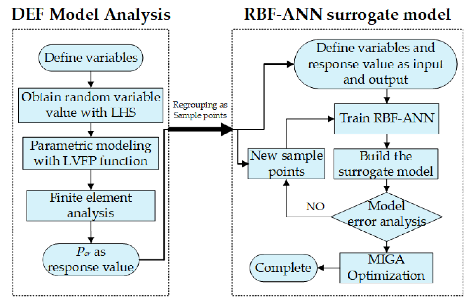
  • Define variables (fiber angles radius and L/D ratio);
  • Obtain random value through Latin Hypercube Sample method;
  • Build the DFE simulation model with the obtained variables;
  • Carry out FE analysis to acquire the critical buckling pressure Pcr and group the variable as a sample point;
  • Define the input and output and build the initial surrogate model with RBF method;
  • Calculate and acquire new sample points from DFE model analysis module to evaluate and reduce the error between surrogate model and the real label value (Pcr obtained from FE analysis based on DFE method);
  • If the error criteria meet the requirement, then stop and complete building the surrogate model, but if not, then go back to step 6 to continue training the surrogate model;
  • When the RBF surrogate model is built, the MIGA is used as the optimization tool to find the optimum Pcr with the corresponding variables.
The detail processes of each method are illustrated in the next section.

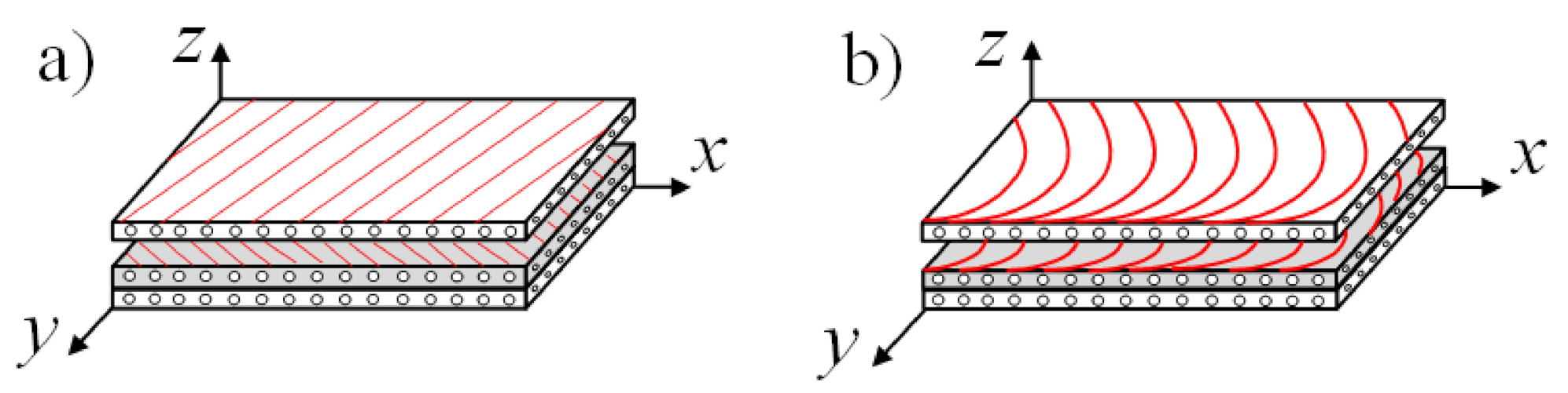
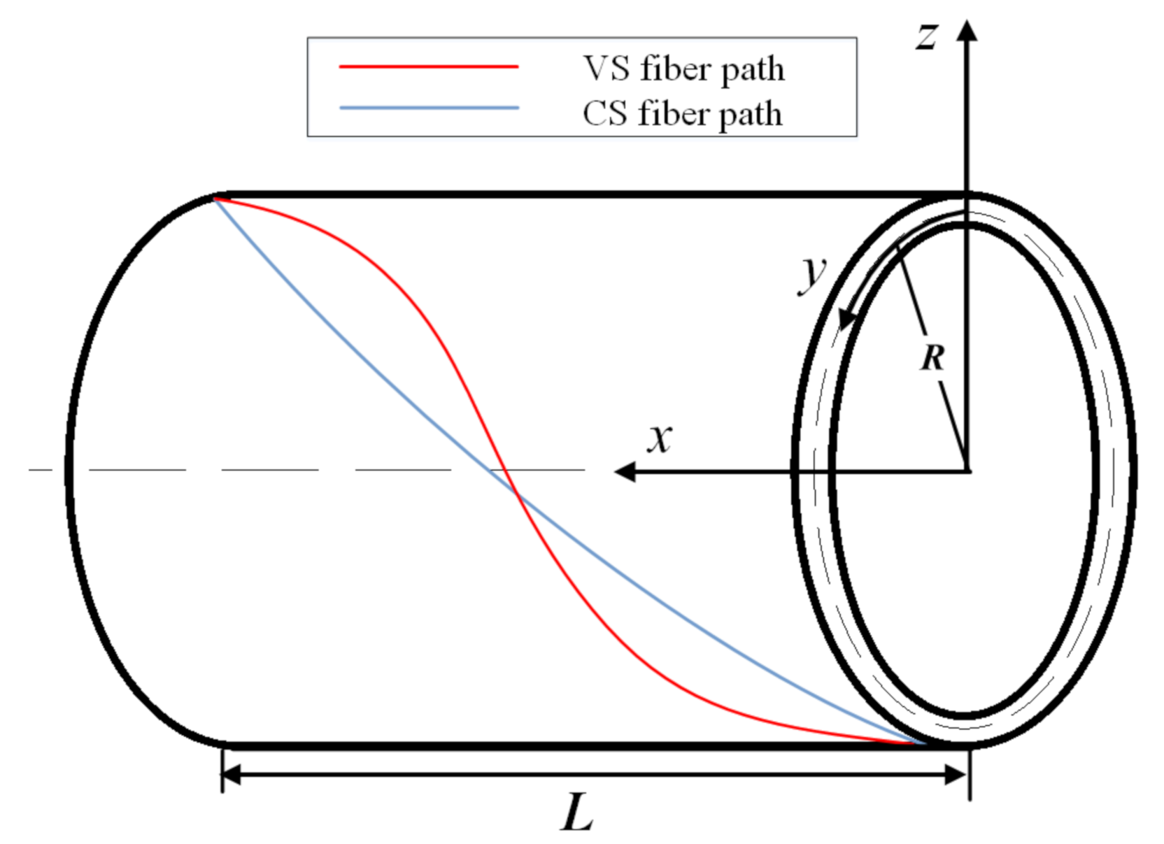
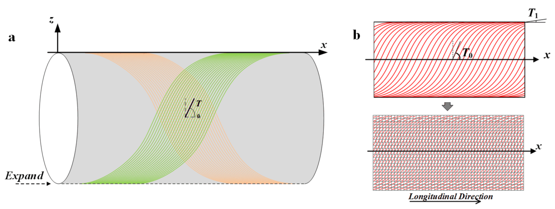
3.1. The DFE Method Based on the Fiber Path Function

Since the AFP machine is improved, the properties of material and structure can be more easily controlled with the variable fiber path. Therefore, one of the key problems of designing and optimizing mechanics for the VS structure is building the appropriate fiber path function to describe the variable angle. Gürdal [31] first gave the idea of linear variation of fiber angle; HONDA et al. [32] proposed a method of two-dimensional cubic function to describe the fiber path; Blom [33] derived different fiber path functions based on conical shell geometry such as constant angle, linearly variable angle, and constant fiber path curvature; Brampton et al. [34] obtained the fiber path function with the level set method. According to the different developed fiber path functions and for simplicity, the present work chooses the linear variation fiber path (LVFP) function proposed by Gürdal and considers the fiber path varying along longitudinal direction. Based on the proposed concept, the fiber angle varies linearly along the coordinate axis, the mathematical model of the fiber path is given as:
θ ( x ) = 2 ( T 1 T 0 ) L | x | + T 0 ,
where T0 and T1 are the midpoint fiber angle and endpoint fiber angle of the fiber path along x-axis, respectively. x is the coordinate value of longitudinal direction. L is the length of the laminate, which here can be denoted by the length of cylinder. It is obvious that the fiber angle will be constant and the model can be turned into the CS composite structures when T0 is equal to T1.
The discrete finite element (DFE) method indicates that the fiber path can be expressed by the finite discrete elements with different constant composite fiber angles. Since the change of the angles between two adjacent elements is small enough, it can be considered that the fiber path is varying linearly [35]. This method is developed and used in the present work to build the simulation model for the VS cylindrical shell. Figure 4 shows the fiber path distribution along a cylindrical side surface. In Figure 4, the cylinder surface is rolled out along circumferential direction. The length of long sides that along x direction equals to the total cylindrical length L. The short sides that are vertical to x-axial denote the edges of cylinder bottom faces. In Figure 4b, the VS fiber path distribution is shown to be based on the DFE method.
Generally, there are two main methods to place the composite fiber tow and fabricate the VS structure based on the LVFP: Shift Method and Parallel Method [36]. The Parallel Method, as its literal meaning, indicates every fiber tow is parallel and all distances between every two tows are identical. For this fabricating method, the wrinkle and gap defect of the fiber band may occur due to the short turning radius as the steering angle increases. While the Shift Method means that each fiber tow will be translated and arranged in a certain direction and distance, as is shown in Figure 4b (shifted along x-axis direction). The overlap usually occurs at the point between two adjacent fiber tow on a cylindrical structure for Shift Method due to the different and variable curvature. In the present study, the Shift Method is used to form the fiber path distribution.

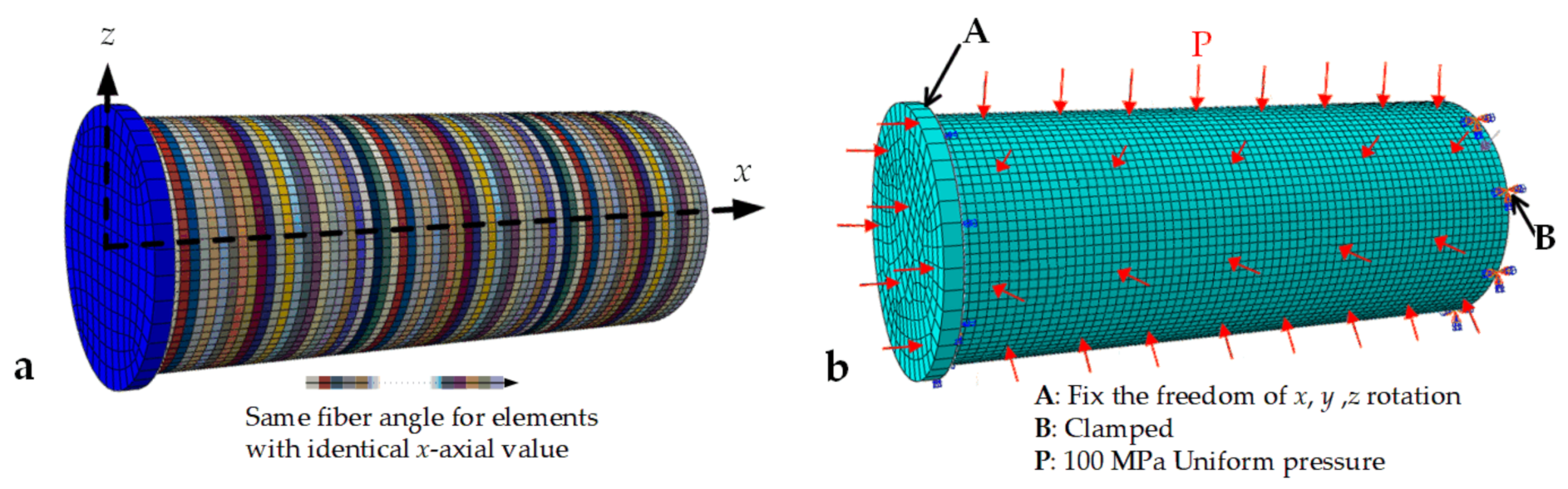
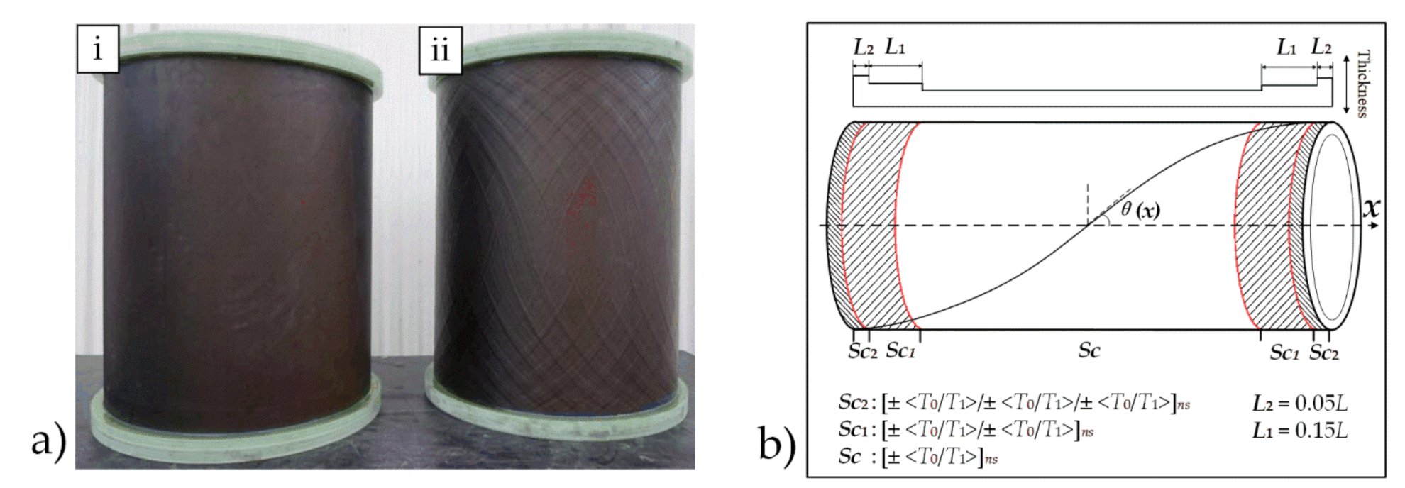
3.2. The DFE Simulation Model with Defects

According to the mentioned fiber path function and DFE method, the simulation model is built with the Python script in ABAQUS. The fiber angle distribution and the 3D model with boundary conditions are shown in Figure 5. It should be noticed that, in this work, the 3D simulation model is built with DFE method based on Shift Method along with the vertical direction of x-axis, which is different from the sketch shown in Figure 4b. The element type for meshing is set as S8R. Considering the boundary condition and for calculation simplicity, the end without cap is set to be tied to the edge to simulate the hydro-static (axial and lateral compression) environment.
Moreover, not only the cylindricity defect is drawn from the linear buckling analysis but also the manufacturing overlap of the parametric model is simulated. For simplicity, in the present work, the overlap simulation is built by the partial thickening of the both ends of the cylindrical shell without considering the relation between the variable thickness and area of the overlap and the changing fiber curvature. Thus, the model includes the cylindricity defects and overlap at the same time. The detail configuration of the overlap simulation is shown in Figure 6. In Figure 6b, section Sc is the main region for layup configuration. Sc1 and Sc2 denote the different types of overlap simulation. n means the number of the symmetric layers. L1 and L2 mean the ratio of defect simulation length to the total cylinder length L.

3.3. The RBF Surrogate Model

The conventional design and optimization method such as the genetic algorithm, which combines with the FE method, usually collects different parameters and uses iterative approach to calculate the fitness function and find the optimum result of concerned parameters. This indicates that the FE analysis is always required in the iteration for repetitive analysis. While the surrogate-model method can significantly simplify the complex and repetitive computing problems through building a model with an enough accuracy and effectiveness by the numerical fitting method. Since the VS composite pressure structure has various and complicated design parameters such as the midpoint angle and endpoint angle, the number of times of FEA will significantly increase with the increased number of variables and structural complexity, which can result in the high-cost design and analysis. This problem can be improved and solved by the surrogate model technique through building a simplified and approximate computing process. There are some developed methods to build surrogate model such as the polynomial regression, radial basis function (RBF), Gaussian process, Kriging model, and support vector regression. For the above methods, although the RBF method has a higher cost of time due to the multi-extreme optimization method, it can ensure the nonsingularity of the parameter matrix because of its monotonic property with the center Euclidean distance. Compared with other mentioned methods, the RBF method can have an accurate result for the high dimensional problems such as the multiple parameters composite design and optimization problems. Thus, it is widely used in composite material field.
In the present study, the surrogate model is trained and built based on the RBF method, a feed-forward artificial neural network model, which consists of the input layer, hidden layer, and output layer. The surrogate model is built with the interpolation and weight calculation by taking the Euclidean distance between the test point and sample point. The geometric parameters and fiber angle of the sample point is defined as variables. The response value is defined as the objective value. The Gaussian radial basis function is chosen to build the surrogate model in the study. The Gaussian radial basis function is described as
G ( x i , c j ) = exp ( 1 2 ( δ j ) x i c j )
y i = j = 1 s w j G ( x i , c j ) = j = 1 s w j exp ( 1 2 ( δ j ) x i c j ) ,
where cj and δj are the center parameter and width parameter of jth hidden layer in neural network, respectively. w is the weight control parameter of output layer. yi is the response value for relative sample point. The error between each response value and sample point, denoted as the loss function, is described as
L o s s = 1 2 i = 1 m ( y i j = 1 s w j G ( x i , c j ) ) 2 ,
where y i ¯ is the sample label, which means the actual value of the sample point. The loss function should be minimized in order to obtain a model with enough accuracy, which means the appropriate cj, δj, and w should be found in each iteration to minimize the value of loss function. The gradient descent method here is used to solve the optimization problem for RBF parameters.
In this paper, the fiber angle T0 and T1, cylinder radius R, and length-diameter ratio L/D are taken as the input parameters. The critical buckling pressure for the VS cylindrical shell is considered as a response value (or predicted value). Moreover, T0 and T1 are from 0° to 90°, L/D ratio is from 1 to 10, and R is from 200 to 400 mm, respectively. The input parameters of the surrogate model are obtained by Latin Hyper-cube Sampling Method (LHS), and the actual response values Pcr corresponding to the input samples are calculated by several FE analyses. When the input and response value are obtained, the surrogate model can be trained and built. The validation work of the DFE and surrogate model for the VS cylindrical shell are explained in the next section.

4. Model Validation

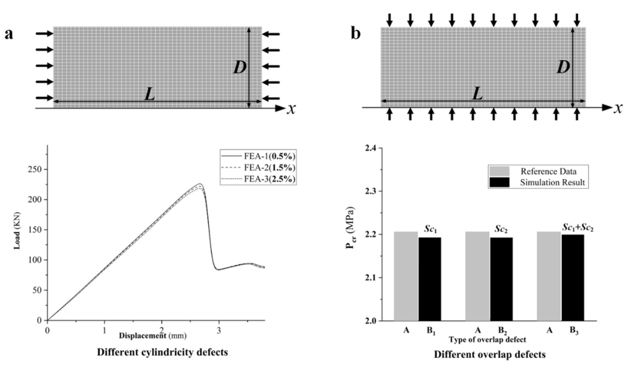
4.1. The Validation of DFE Simulation Model

In order to verify the built DFE simulation model for the VS cylindrical shell, two different situations are taken into account according to the analysis condition setting of references. The VS cylindrical shell is compressed under axial compression and lateral compression to do the buckling analysis. Table 1 shows the material properties and geometric parameters for the corresponding boundary conditions.
The simulation model is built with the mentioned LVFP function and parameters in Table 1. Several times of nonlinear FE analyses are conducted with risk approach to compare with the data from the reference. Both two different defect simulations are drawn into the model. The nonlinear analysis results are obtained and shown in Figure 7. In Figure 7a, 3 different nonlinear buckling FE analysis results represent that the model is built with different proportions (0.5%, 1.5%, and 2.5%) of the cylindricity defect. The cylindricity defect is simulated through the eigenmode of the linear prebuckling analysis result. The overlap simulation is set same as mentioned in Figure 6 (Sc1 and Sc2 section). The displacement-load curve shows that the axis compression changes at around 221 kN, whose displacement is 2.5 mm. It means that the average value of buckling load for the validation work here is 6% higher than the value (208 kN) obtained by the experimental method in Ref. [26]; meanwhile, the displacement error is 8% compared with the experimental data (2.3 mm). In Figure 7b, the 3 different FE results are obtained by considering different overlap simulation with identical cylindricity defect proportion. In Figure 7b, B1 means that the model is built only with Sc1 simulation at L2 mentioned in Figure 6; B2 is built only with Sc2 simulation at L2; B3 has Sc1 and Sc2 simulations at L1 and L2, respectively. In Figure 7b, the average Pcr obtained by the nonlinear buckling analysis increases, which is lower than that in Ref. [37]. This error may result from the consideration of the overlap and cylindricity defect simulation. In general, the reasons that lead to these kinds of differences in Figure 7a,b can be as follows. (1) The built defect simulation of the model is simpler and is different from the defect of the actual manufacturing structures. Those defects, such as displacement fields of cylindricity and planeness, can be measured by professional experimental equipment (e.g., the digital image correlation system). (2) The approximate boundary conditions are different from the reference’s model. (3) For the lateral compression, the present model considered the overlap and nonlinear process, while the reference result was obtained by the linear buckling analysis without considering the defects. According to the comparison results, it is obvious that these tiny model errors can be reduced by adjusting the simulation model such as obtaining the defects with the experimental model and measurement. Generally, the comparison results demonstrate that the proposed DFE method based on the LVFP function is valid and accurate enough to express the Pcr analysis for the VS cylindrical shell.

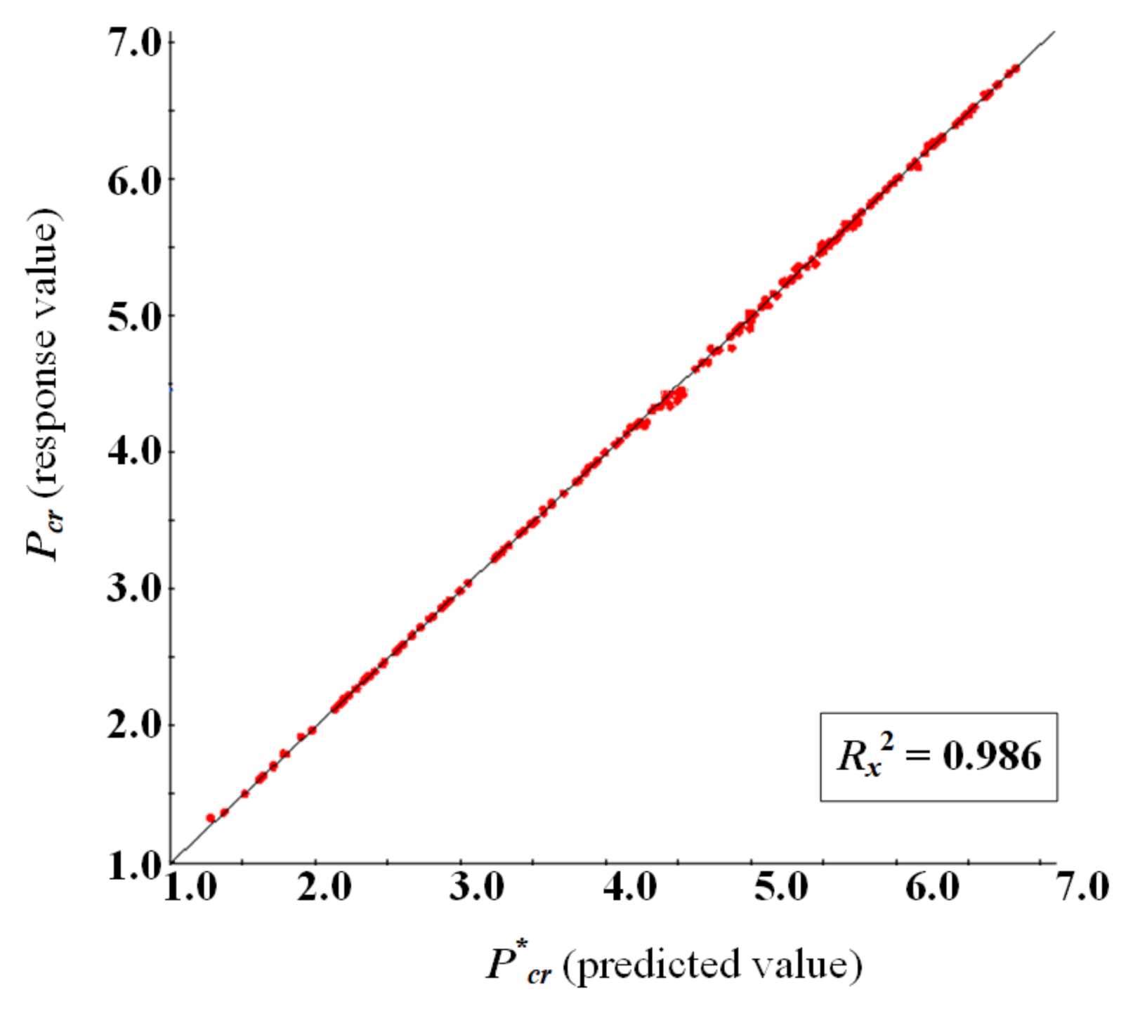
4.2. Surrogate Model Error Analysis

Based on the mentioned processes in Figure 3, 100 sets of sample points as well as the corresponding response value Pcr are obtained to build the surrogate model for the model error analysis. Material properties and layup configuration are selected from Table 1a. Figure 8 shows the contour map of the built surrogate model about T0 and T1 corresponded with R = 250 mm. The formula of complex correlation coefficient Rx2, which is used to evaluate the error between the actual and response value of a surrogate model, is given as
R x 2 = 1 i = 1 q ( y i y i ) 2 i = 1 q ( y i Y ) 2 ,
where q is the number of sample points; y i ¯ is the actual value, y i is the predicted value (obtained by surrogate model), and Y is the average actual value. Here, if Rx2 is closer to 1, then, the model will have a higher accuracy and if Rx2 is more than 0.9, then, the model can be considered as valid with enough amount of sample points. Figure 9 shows the error analysis results from the above surrogate model compared with 50 new random sample points. From error analysis diagram, it can be obviously seen that all the points are around the y = x function line, where Rx2 is 0.986. It indicates that the predicted value has the high coincidence with the actual value. Therefore, the result demonstrates that the RBF-based surrogate model is accurate enough for the design and optimization problem.
When model validation and error analysis are introduced, the surrogate model is finally built by the Python program with the obtained sample points, and the design and optimization processes are integrated.

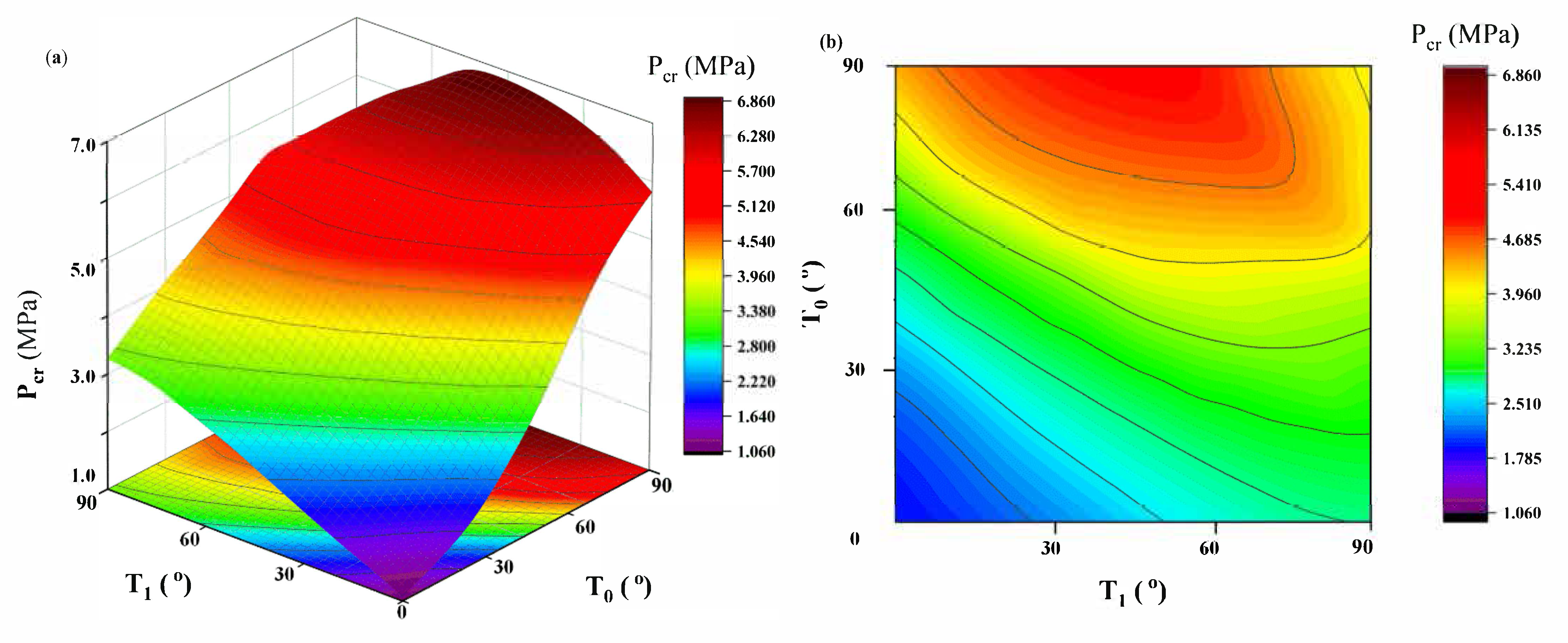
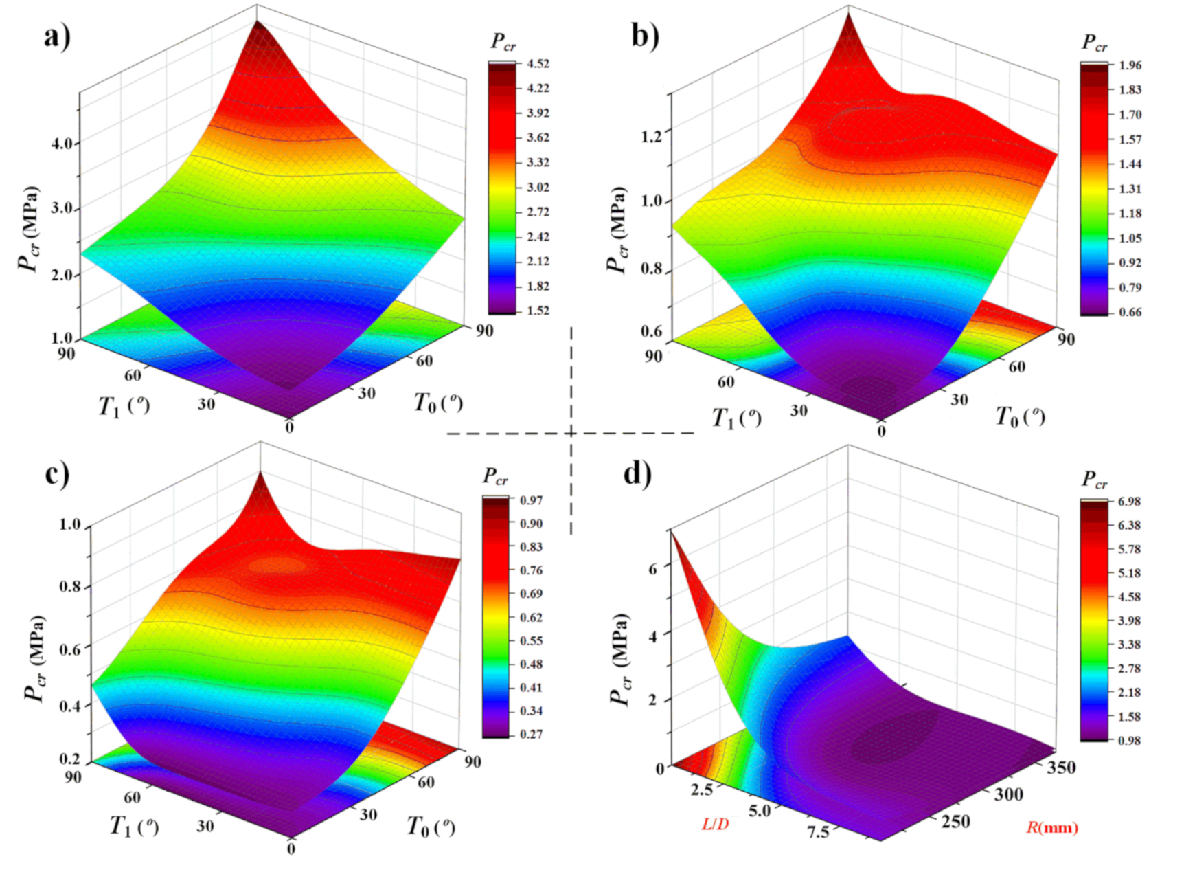
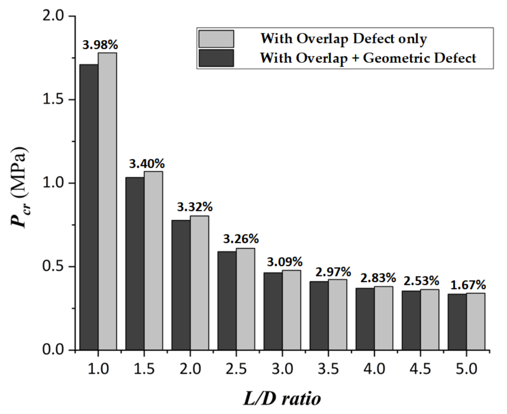
5. Results and Discussions

This work mainly analyzes the relation among Pcr, fiber angle distribution, and geometric parameters for the VS cylindrical shell with the defect. The optimum Pcr corresponding with optimized fiber angle for both the VS and CS cylindrical shells is obtained to discuss the improvement of Pcr under the identical boundary conditions and fixed geometric parameters. The chosen material properties are from Table 1b and two kinds of defects (the overlap and cylindricity defects) are taken into account at the same time. The thickness is 0.146 mm, and the stacking sequence for the VS and CS cylindrical shell are ± <T0/T1>12s and ± [θ]12s, respectively. It should be noted that the analysis and optimization work is complete without considering the manufacturability such as minimum turning radius constraint.
The surrogate model is built about the critical buckling pressure corresponding with 100 sample points of the fiber angle and cylindrical radius for the VS cylindrical shell. In the present study, the surrogate model is considered to be completed when the complex correlation coefficient Rx2 is larger than 0.98. The 3D map diagram of the surrogate model is shown in Figure 10. In Figure 10a–c, the fixing radius is 200, 250, and 300 mm and L/D ratio is 2, 3, and 4, respectively. Besides, Figure 10d shows the relation among L/D ratio, cylindrical radius, and Pcr with T0 = 45° and T1 = 60°. The first three diagrams in Figure 10 imply that the maximum critical buckling pressure occurs around the large fiber angle, which is close to 90° when the variable fiber angle with fixed geometry is considered. For the certain fiber angle, it is obvious that the maximum critical buckling pressure can be found when the cylinder has the small radius and L/D ratio.
According to the surrogate model, this study uses different radius and L/D ratio with certain fiber angle (here <T0/T1> = <60°/30°>) to discuss the relation between Pcr and geometric parameters of the cylindrical shell. Meanwhile, the comparisons of buckling analysis with and without considering the defects, are also discussed. Table 2 shows the acquired results. The defect consideration part in Table 2 means that the Pcr is obtained from the RBF-based surrogate model whether both two types of defects (overlap and cylindricity defect) are taken into account at the same time. For the VS cylindrical shell with same certain fiber angle distribution (T0 = 60° and T1 = 30° as in Table 2) and radius, Pcr decreases with the increment of L/D ratio. For the cylindrical shell with the identical L/D ratio, the critical buckling pressure also decreases with the increment of cylindrical radius. Meanwhile, it is certain that Pcr obtained from a model with the cylindricity defects is lower than that of the model without the cylindricity defects. The above patterns for the VS cylindrical shell are similar with those for the CS cylindrical shell. In another word, it also indicates that the built model based on the DEF simulation and the surrogate model is valid and can be used to acquire the critical buckling pressure for the VS cylindrical shell. In addition, the effect of the model defect on Pcr decreases with the increment of L/D ratio when the defects are taken into account. This is because that when the L/D ratio and the structure size are large enough, the structural instability is more sensitive to the cylindrical geometry than to the defect. Figure 11 shows the effect of defect on the critical buckling pressure analysis obtained by surrogate model for the VS cylindrical shell. In Figure 11, it also can be seen that the effect of defect decreases with the increment of L/D ratio.
When Pcr can be obtained through the proposed method, the optimization and comparison works are finished in order to study the effect of the changing L/D ratio on the optimum Pcr and the improvement of optimum Pcr for both VS and CS cylindrical shells. As mentioned before, because the Multi-Island Genetic Algorithm (MIGA) method has a good convergence on solving the optimization problem of stacking sequence for composite cylinders, it is taken as the optimization tool here to optimize the built surrogate model and get the optimization results. The fiber angles T0 and T1 are considered as design variables here, and the maximum of the critical buckling pressure Pcr is considered as the objective. The number of Multi-Island is set to 3; and the number of offspring is set to 10 [38]. In addition, the fiber angle T0 and T1 has the range of (0°, 90°) and (15°, 90°), respectively. The cylindrical radius is 200 mm. The L/D ratio is from 1 to 7. The material properties and boundary are same as those of VS analysis. Table 3 gives the comparison result of research parameters between the VS and CS cylindrical shells. From the comparison, it can be obviously seen that the optimum Pcr for the VS cylindrical shell is improved up to 21.1%, compared with that of the CS cylindrical shell under the same load condition and geometric parameters.
Table 3 also shows that the optimum Pcr decreases with the increment of L/D ratio for the VS and CS cylindrical shells. This pattern is also similar with Pcr from the surrogate model. Figure 12 shows the improvement and the optimum value of Pcr for both the CS and VS cylindrical shells. The improvement of the optimum Pcr between the VS and CS cylindrical shells barely increases with the L/D ratio from 1 to 2.5, and it decreases with the variation of L/D ratio from 4 to 7. The maximum of the improvement will reach at 21.1% when the L/D ratio is about 3. This improvement may mainly result from the moderate geometric parameters such as cylinder radius and length, and the lateral and axial pressure will both obtain the most benefit from the optimized variable fiber path to increase the Pcr with this L/D ratio and radius. In Figure 12b, when the L/D ratio is greater than 5, Pcr and its improvement are very small. It is because that when the L/D increases, the lateral pressure has less effect on the buckling pressure than that of the axis pressure. In addition, in Figure 12 and Table 3, the fiber angle at the mid-point of the cylinder length (T0) is close to 90° when the optimum Pcr occurs. This can be explained as when the fiber angle is close to 90° at the middle of the cylinder, the angle distribution can be considered as the partial stiffener rings in the circumferential direction. Hence, this situation can be helpful for improving the buckling pressure for the VS cylindrical shell.
Furthermore, after building the surrogate model for the VS composite cylindrical shell, the calculation efficiency and accuracy are studied. The results from the conventional FE method and surrogate model are discussed and compared for a VS cylindrical shell. Here, the L/D ratio is from 2 to 7 and R is 200 mm. The material properties are also from Table 1a. The stacking sequence is set as [±<60°/15°>]12s according to the defect simulation method mentioned in Section 2. The cylinder radius is considered as the input. The response value is Pcr. The results are shown in Table 4.
To study the calculation efficiency of the surrogate model built with DFE method, in Table 4, the calculation time means the time starts only from the calculation of inputting the parameters and ends at the time when Pcr is acquired. The time of building simulation and surrogate models is not considered. The process time is recorded by the Python program. In addition, to ensure the accuracy of the simulation model, the element size keeps a constant ratio ES of the cylinder diameters D, in which ES = 0.04D. This process only considers the linear buckling analysis since the nonlinear process is related and more sensitive to many other factors such as the increment setting and mesh size. From the results in Table 4, the total time cost for the acquiring Pcr is significantly optimized. It is because that the FE analysis process is skipped by the surrogate mode and Pcr can be acquired directly by inputting T0 and Tl. The results in Table 4 also show that the calculation time of the conventional FE method obviously increases with the structure size, while the surrogate model method is less sensitive to the structure size. Meanwhile, the response value (Pcr) error is up to 6.2% for the obtained results. The results reflect that the error of Pcr is small enough between two methods. It indicates that when the researchers want to obtain Pcr for the VS cylindrical shell in a fast and accurate method, the error can be acceptable. Thus, in Table 4, when it comes to a large number of repetitive FE analysis situation, the built model based on the RBF can have enough accuracy and efficiency.

6. Conclusions

The present work is focused on the critical buckling pressure analysis for the VS cylindrical shell. The simulation and surrogate models are proposed to study the critical buckling pressure for the VS cylindrical shell. The results indicate that the proposed DFE method can precisely express the properties for the VS composite cylindrical shell. In addition, the RBF-based surrogate model is an effective and accurate method for solving the VS cylindrical shell problem. The main conclusions are drawn as below:
  • The VS simulation model based on the DFE with the LVFP function can accurately describe the critical buckling pressure for the VS cylindrical shell with the defects under the combination compression.
  • The proposed design and optimization method has higher efficiency for the critical buckling pressure analysis for the VS cylindrical shell than that for the FEA.
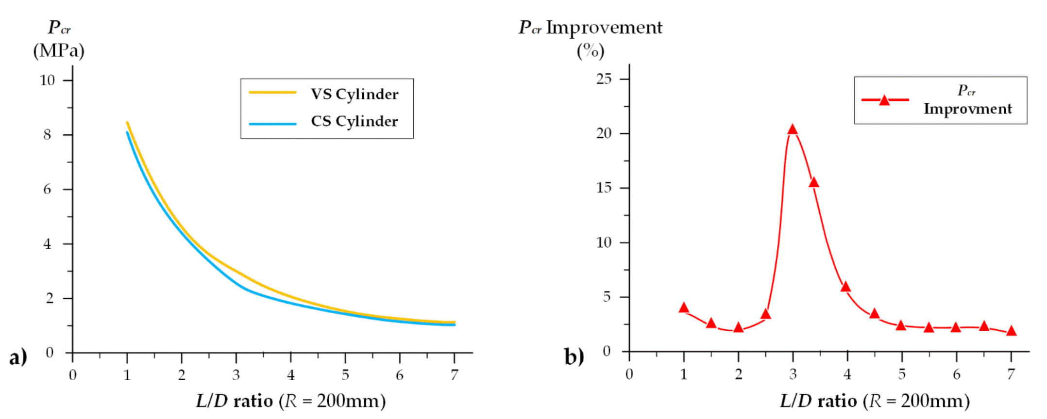
  • The optimum Pcr for the VS cylindrical shell can be improved by 21.1% compared with that of the CS cylindrical shell under the same geometry, material properties, and boundary condition. In addition, the maximum improvement of Pcr will occur when the midpoint fiber angle is close to 90° and the L/D ratio is around 3.
Following work will focus on optimizing the failure strength and the natural frequency in the experimental and simulation methods.

Author Contributions

Conceptualization, Z.Y.; Data curation, Z.Y.; Formal analysis, Z.Y.; Funding acquisition, Y.C.; Investigation, Z.Y.; Methodology, Z.Y.; Resources, Y.C.; Software, Z.Y.; Supervision, Y.C.; Validation, J.L.; Visualization, Z.Y.; Writing—original draft, Z.Y.; Writing—review & editing, J.L. All authors have read and agreed to the published version of the manuscript.

Funding

This research was funded by the National Natural Science Foundation of China, grant number 51909219. The APC was funded by the Fundamental Research Funds for the Central Universities (3102019JC006).

Institutional Review Board Statement

Not applicable.

Informed Consent Statement

Not applicable.

Data Availability Statement

Not applicable.

Conflicts of Interest

The authors declare no conflict of interest. The funders had no role in the design of the study; in the collection, analyses, or interpretation of data; in the writing of the manuscript, or in the decision to publish the results.

References

  1. Hur, S.-H.; Son, H.-J.; Kweon, J.-H.; Choi, J.-H. Postbuckling of composite cylinders under external hydrostatic pressure. Compos. Struct. 2008, 86, 114–124. [Google Scholar] [CrossRef]
  2. Khani, A.; Abdalla, M.; Gurdal, Z. Optimum tailoring of fibre-steered longitudinally stiffened cylinders. Compos. Struct. 2015, 122, 343–351. [Google Scholar] [CrossRef]
  3. Prasanna, A.B.; Raju, K.S.; Ramji, K.; Satish, P. Free Vibration, Buckling and Design Optimisation of Composite Pressure Hulls. Mater. Today Proc. 2017, 4, 7381–7387. [Google Scholar] [CrossRef]
  4. Craven, R.; Graham, D.; Dalzel-Job, J. Conceptual design of a composite pressure hull. Ocean Eng. 2016, 128, 153–162. [Google Scholar] [CrossRef]
  5. Li, B.; Pang, Y.; Zhu, X.; Cheng, Y. 6σ Optimization Design of Ring-stiffened Composite Pressure Hull of Underwater Vehicle. Acta Armamentarii 2018, 39, 1172–1177. [Google Scholar]
  6. A. Luersen, M.; A. Steeves, C.; Nair, P.B. Curved fiber paths optimization of a composite cylindrical shell via Kriging-based approach. J. Compos. Mater. 2015, 49, 3583–3597. [Google Scholar] [CrossRef]
  7. Chen, X.; Wu, Z.; Nie, G.; Weaver, P. Buckling analysis of variable angle tow composite plates with a through-the-width or an embedded rectangular delamination. Int. J. Solids Struct. 2018, 138, 166–180. [Google Scholar] [CrossRef] [Green Version]
  8. Cheng, Y.; Pang, Y.; Yang, Z. Research on Composite Material Pressure Hulls Based on Approximation. Ship Eng. 2015, 37, 74–78. [Google Scholar]
  9. Huang, G.; Wang, H.; Li, G. An efficient reanalysis assisted optimization for variable-stiffness composite design by using path functions. Compos. Struct. 2016, 153, 409–420. [Google Scholar] [CrossRef]
  10. Almeida, J.H.S.; Bittrich, L.; Jansen, E.; Tita, V.; Spickenheuer, A. Buckling optimization of composite cylinders for axial compression: A design methodology considering a variable-axial fiber layout. Compos. Struct. 2019, 222, 110928. [Google Scholar] [CrossRef]
  11. Peeters, D.M.; Hesse, S.; Abdalla, M.M. Stacking sequence optimisation of variable stiffness laminates with manufacturing constraints. Compos. Struct. 2015, 125, 596–604. [Google Scholar] [CrossRef]
  12. Peeters, D.; Abdalla, M. Design Guidelines in Nonconventional Composite Laminate Optimization. J. Aircr. 2017, 54, 1454–1464. [Google Scholar] [CrossRef] [Green Version]
  13. Liang, C.-C.; Chen, H.-W.; Jen, C.-Y. Optimum design of filament-wound multilayer-sandwich submersible pressure hulls. Ocean Eng. 2003, 30, 1941–1967. [Google Scholar] [CrossRef]
  14. Lee, G.-C.; Kweon, J.-H.; Choi, J.-H. Optimization of composite sandwich cylinders for underwater vehicle application. Compos. Struct. 2013, 96, 691–697. [Google Scholar] [CrossRef]
  15. Blom, A.W.; Stickler, P.B.; Gürdal, Z. Optimization of a composite cylinder under bending by tailoring stiffness properties in circumferential direction. Compos. Part B Eng. 2010, 41, 157–165. [Google Scholar] [CrossRef]
  16. Almeida, J.H.S.; Ribeiro, M.L.; Tita, V.; Amico, S. Damage and failure in carbon/epoxy filament wound composite tubes under external pressure: Experimental and numerical approaches. Mater. Des. 2016, 96, 431–438. [Google Scholar] [CrossRef]
  17. Almeida, J.H.S.; Tonatto, M.L.; Ribeiro, M.L.; Tita, V.; Amico, S. Buckling and post-buckling of filament wound composite tubes under axial compression: Linear, nonlinear, damage and experimental analyses. Compos. Part B Eng. 2018, 149, 227–239. [Google Scholar] [CrossRef]
  18. Tyazhel’Nikov, V.V.; Semenkov, V.E.; Ryabkov, V.A.; Stambul’Chik, M.A.; Bogorodskii, A.A. Improving the quality of wheel-tire steel by optimizing the addition of complex titanium-bearing deoxidizers. Compos. Struct. 1988, 32, 270–271. [Google Scholar] [CrossRef]
  19. Hu, J.; Sundararaman, S.; Menta, V.G.K.; Chandrashekhara, K.; Chernicoff, W. Failure Pressure Prediction of Composite Cylinders for Hydrogen Storage Using Thermo-mechanical Analysis and Neural Network. Adv. Compos. Mater. 2009, 18, 233–249. [Google Scholar] [CrossRef]
  20. Nik, M.A.; Fayazbakhsh, K.; Pasini, D.; Lessard, L. Surrogate-based multi-objective optimization of a composite laminate with curvilinear fibers. Compos. Struct. 2012, 94, 2306–2313. [Google Scholar] [CrossRef] [Green Version]
  21. Almeida, J.H.S.; Ribeiro, M.L.; Tita, V.; Amico, S. Stacking sequence optimization in composite tubes under internal pressure based on genetic algorithm accounting for progressive damage. Compos. Struct. 2017, 178, 20–26. [Google Scholar] [CrossRef]
  22. Hao, P.; Wang, B.; Li, G. Surrogate-Based Optimum Design for Stiffened Shells with Adaptive Sampling. AIAA J. 2012, 50, 2389–2407. [Google Scholar] [CrossRef]
  23. Hao, P.; Wang, B.; Li, G.; Tian, K.; Du, K.; Wang, X.; Tang, X. Surrogate-based optimization of stiffened shells including load-carrying capacity and imperfection sensitivity. Thin Walled Struct. 2013, 72, 164–174. [Google Scholar] [CrossRef]
  24. Rouhi, M.; Ghayoor, H.; Fortin-Simpson, J.; Zacchia, T.T.; Hoa, S.V.; Hojjati, M. Design, manufacturing, and testing of a variable stiffness composite cylinder. Compos. Struct. 2018, 184, 146–152. [Google Scholar] [CrossRef] [Green Version]
  25. Wang, Z.; Almeida, J.H.S., Jr.; St-Pierre, L.; Wang, Z.; Castro, S.G. Reliability-based buckling optimization with an accelerated Kriging metamodel for filament-wound variable angle tow composite cylinders. Compos. Struct. 2020, 254, 112821. [Google Scholar] [CrossRef]
  26. Labans, E.; Bisagni, C. Buckling and free vibration study of variable and constant-stiffness cylindrical shells. Compos. Struct. 2019, 210, 446–457. [Google Scholar] [CrossRef]
  27. Shen, K.; Pan, G.; Shi, Y. Optimization of Composites Shell Subjected to Hydrostatic Pressure to Maximize Design Pressure Factor. J. Ship Mech. 2017, 21, 1552–1563. [Google Scholar] [CrossRef]
  28. Wei, R.; Pan, G.; Jiang, J.; Shen, K.; Lyu, D. An efficient approach for stacking sequence optimization of symmetrical laminated composite cylindrical shells based on a genetic algorithm. Thin Walled Struct. 2019, 142, 160–170. [Google Scholar] [CrossRef]
  29. Chun, S.K.; Guang, P. Optimizing the buckling strength of filament winding composite cylinders under hydrostatic pressure. J. Reinf. Plast. Compos. 2018, 37, 892–904. [Google Scholar] [CrossRef]
  30. László, P.K.; George, S.S. Mechanics of Composite Structures; Cambridge University Press: Cambridge, UK, 2003; pp. 68–83. [Google Scholar]
  31. Gürdal, Z.; Tatting, B.; Wu, C. Variable stiffness composite panels: Effects of stiffness variation on the in-plane and buckling response. Compos. Part A Appl. Sci. Manuf. 2008, 39, 911–922. [Google Scholar] [CrossRef]
  32. Honda, S.; Narita, Y. Vibration design of laminated fibrous composite plates with local anisotropy induced by short fibers and curvilinear fibers. Compos. Struct. 2011, 93, 902–910. [Google Scholar] [CrossRef] [Green Version]
  33. Blom, A.W.; Tatting, B.F.; Hol, J.M.; Gürdal, Z. Fiber path definitions for elastically tailored conical shells. Compos. Part B Eng. 2009, 40, 77–84. [Google Scholar] [CrossRef]
  34. Brampton, C.J.; Wu, K.C.; Kim, H.A. New optimization method for steered fiber composites using the level set method. Struct. Multidiscip. Optim. 2015, 52, 493–505. [Google Scholar] [CrossRef]
  35. Wang, H.; Li, Q.; Li, G. Review on Structure Design and Uncertainty Analysis of Variables Stiffness Composites. Chin. J. Mech. Eng. 2019, 55, 46–55. [Google Scholar] [CrossRef] [Green Version]
  36. Ma, Y.Q.; Zhang, S.J.; XU, Z.Y. The Buckling of Variable-Stiffness Composite Panels with Curvilinear Fiber Format. J. Reinf. Plast. Compos. 2009, 5, 31–35. [Google Scholar] [CrossRef]
  37. Nopour, H.; Ataabadi, A.K.; Shokrieh, M.M. Correction to: Fiber Path Optimization in a Variable-Stifness Cylinder to Maximize Its Buckling Load Under External Hydrostatic Pressure. Mech. Compos. Mater. 2019, 55, 139. [Google Scholar] [CrossRef] [Green Version]
  38. Song, B.; Lyu, D.; Jiang, J. Optimization of composite ring stiffened cylindrical hulls for unmanned underwater vehicles using multi-island genetic algorithm. J. Reinf. Plast. Compos. 2018, 37, 668–684. [Google Scholar] [CrossRef]
Figure 1. The section of composite material laminate: (a) CS and (b) VS configuration.
Jmse 09 00637 g001
Figure 2. A cylindrical geometry.
Jmse 09 00637 g002
Figure 3. Flow chart of design and optimization method.
Jmse 09 00637 g003
Figure 4. Fiber path diagram for a cylinder side surface: (a) fiber path along 3D cylinder surface and (b) 2D fiber path and simulation of DFE method.
Jmse 09 00637 g004
Figure 5. The DFE simulation model: (a) fiber angle distribution based on Shift Method and (b) boundary condition.
Jmse 09 00637 g005
Figure 6. The overlap and the configuration of simulation model: (a) i: the CS cylinder and ii: the VS cylinder with overlap, reproduced with the permission of ref. [26], copyright@Elsevier, 2019 and (b) the configuration of the overlap simulation.
Jmse 09 00637 g006
Figure 7. Model validation with different defect cases: (a) the load-displacement curve for the cylinder under axial compression and (b) Pcr for the cylinder under lateral compression.
Jmse 09 00637 g007
Figure 8. The contour map of RBF test surrogate model for Pcr: (a) 3D and (b) 2D.
Jmse 09 00637 g008
Figure 9. Error analysis with complex correlation coefficient Rx2.
Jmse 09 00637 g009
Figure 10. Contour maps of variables distribution with critical buckling pressure Pcr for surrogate model built with different parameters of a VS cylindrical shell: (a) T0, T1, and response Pcr with R = 200 mm, L/D = 2; (b) T0, T1, and response Pcr with R = 250 mm, L/D = 3; (c) T0, T1, and response Pcr with R = 300 mm, L/D = 4; and (d) L/D, R, and response Pcr with T0 = 45°, T1 = 60°.
Jmse 09 00637 g010
Figure 11. Effect of different defects on Pcr.
Jmse 09 00637 g011
Figure 12. The optimum Pcr and Pcr improvement for different L/D ratio: (a) the optimum Pcr of VS and CS cylinders and (b) the Pcr improvement between VS and CS cylinders.
Jmse 09 00637 g012
Table 1. Material properties and geometric parameters for different test cases: (a) axial compression and (b) lateral compression.
(a) Axial Compression
Material PropertiesElastic ModulusShear ModulusPoisson RatioTensile StrengthCompress StrengthShear Strength
SymbolE11E12G12μ12XtYtXcYcS
Value14110.34.50.3170195.41163244116.5
UnitGPaGPaGPa-MPaMPaMPaMPaMPa
Geometric ParametersRadiusLengthLayer ThicknessStacking Sequence
Value3007900.181[± 45°/± <15°/60°>]s
Unitmmmmmmdegree
(b) Lateral Compression
Material PropertiesElastic ModulusShear ModulusPoisson RatioTensile StrengthCompress StrengthShear Strength
SymbolE11E12G12μ12XtYtXcYcS
Value147950.32004531197204137
UnitGPaGPaGPa-MPaMPaMPaMPaMPa
Geometric ParametersRadiusLengthLayer ThicknessStacking Sequence
Value25012500.146[± <90°/75°>]12s
Unitmmmmmmdegree
Table 2. Critical buckling pressure obtained from surrogate model, T0 = 60° and T1 = 30°.
L/DPcr (MPa)
R = 200 mmR = 250 mmR = 300 mmDefect Consideration, R = 350 mm
With Overlap OnlyWith Overlap and Geometric Defect
1.07.33173.79012.38851.78081.7098
1.54.42712.49031.53281.07031.0339
2.03.07841.88581.28370.80370.7770
2.52.35111.29870.83780.60970.5898
3.02.07161.11940.69520.47810.4633
3.51.91171.02340.62610.42310.4105
4.01.48030.94860.57450.38110.3703
4.51.19140.74330.53280.36320.3540
5.01.05190.57140.45610.34130.3356
Table 3. The optimum Pcr for the VS and CS cylindrical shell.
L/DVS Cylindrical ShellCS Cylindrical ShellPcr
Improvement
(%)
Optimum Fiber Angle
(Degree)
Optimum
Pcr
(MPa)
Optimum Fiber Angle
(Degree)
Optimum
Pcr
(MPa)
1.0± <89/48>12s8.5362± [80]12s8.19014.2
1.5± <89/27>12s5.7778± [79]12s5.40116.9
2.0± <86/79>12s4.5174± [89]12s4.42652.1
2.5± <80/75>12s3.9861± [73]12s3.75106.3
3.0± <87/31>12s3.1214± [78]12s2.578621.1
3.5± <88/45>12s2.4590± [84]12s2.113816.3
4.0± <89/51>12s2.0091± [89]12s1.90095.7
4.5± <89/85>12s1.8358± [89]12s1.78332.9
5.0± <89/87>12s1.7595± [89]12s1.71262.3
5.5± <89/87>12s1.7067± [89]12s1.66832.3
6.0± <89/86>12s1.6791± [89]12s1.63882.5
6.5± <88/82>12s1.6451± [89]12s1.61671.8
7.0± <88/82>12s1.6223± [89]12s1.60261.2
Table 4. Calculation efficiency (T0 = 60° and T1 = 15°).
L/D (R = 200 mm)Calculation Time (s)Pcr Value (MPa)
FERBFFERBFPcr Error (%)
2.013.10.93.29233.08696.2
2.513.20.92.13502.24495.1
3.013.60.81.88611.90310.9
3.514.70.91.65001.71513.9
4.017.81.01.62351.55474.2
4.519.11.01.41151.40190.7
5.021.70.91.16261.13472.4
5.522.00.80.91480.97076.1
6.024.11.00.83630.78695.9
6.524.90.90.76110.71536.0
7.026.00.80.72650.68775.3
Publisher’s Note: MDPI stays neutral with regard to jurisdictional claims in published maps and institutional affiliations.

