1. Introduction
As one of the most important modes of transportation in the world trade, the shipping industry has attracted great attention, focusing on safety. Any accidents at sea cause huge economic and life losses, as well as environmental damage. Many regulations and measures formulated by IMO, vessel’s flag state, port state and vessel owners were taken to ensure the safety of vessels, but maritime accidents still frequently happen. Study shows that more than 80 percent of accidents at sea are caused by human factors [
1]. More than 56% of vessel collisions, which resulted in serious maritime accidents, were caused by a vessel navigator’s failure to correctly understand and execute the International Regulations for preventing collisions at sea, 1972 (COLREGs, 1972) [
2]. The intellectualization of vessels has gradually become a major trend in developing the global shipping industry. Maritime autonomous surface ships (MASS) will adopt advanced automatic sensing and intelligent decision-making technology, replacing the crew for decision-making and reducing mistakes caused by human factors. Moreover, then maritime accidents are expected to be reduced [
3]. International Maritime Organization (IMO) has defined the following four degrees of autonomy related to MASS [
4]. At the highest degree of autonomy, a fully autonomous vessel is defined as a MASS whose operating system can make decisions autonomously and complete autonomous collision-avoidance (ACA) actions by itself. The operating system should first intelligently identify the encountering situation conforming to COLREG rules and then determine the ACA actions that can be carried out by the own vessel (OS). However, COLREG rules are composed of vague sentences and vocabularies whose core meanings are closely concerned with sea practice. How to quantitatively analyze COLREG rules is a vitally important bottleneck problem. Moreover, any feasible decision plan made by the ACA decision system should be able to be carried out by the OS. Therefore, to ensure the plan to be operational, the maneuvering process of the OS in the ACA scheme should be deducted and checked before decision-making.
Vessel ACA decision-making technologies have been studied for more than half a century, and fruitful research results have been developed. The geometric analysis method, including the geometric model solving the distance to the closest point of approaching (DCPA) and the time to the closest point of approaching (TCPA), has instructed vessel captain or officer on watch to take appropriate collision-avoidance actions in sea practice for several decades [
5]. Vehicle obstacle avoidance theory based on judging the angle relation between the relative speed and relative position of two vessels gives the feasible path range of collision-avoidance action [
6]. The expert system is also applied in the field of the ACA. It builds a knowledge base from COLREGs, good seamanship and captains’ practical experience in collision avoidance. Lee [
7] presented a fuzzy logic algorithm for the optimal collision-avoidance scheme based on the requirement COLREG rules and vessel motion data. Maneuvering experiences of captains in different situations were considered simultaneously. With developing information theory, cybernetics and system theory, studying vessel collision-avoidance upgraded to a new stage. In studying vessel collision avoidance using neural networks, collision-avoidance decisions are mainly triggered by collision risk index (CRI) [
2]. At the same time, deep learning-based collision-avoidance decisions represented by genetic algorithms also provide new models for the ACA research [
8]. The genetic algorithm converts the vessel’s path into a series of way-points and looks for an optimal path for the OS based on safety and economy. With the continuous progress of research, researchers have gradually shifted their study to decision-making for collision avoidance among multiple ships. A method that combines offline optimal path planning and restricted A* algorithm uses the artificial potential field to expand online adaptive weighting based on the USV maneuvering response time was proposed by Singh, etc. [
9,
10]. This method can be used for multi-ship path decision-making.
Many previous studies have focused on the vessel except the stand-on vessel at risk of collision, which should take collision-avoidance actions as early as possible [
11]. He (2015) quantified the action of the give-way vessel in the crossing situation [
12]. Zheng and Wu (1999) gave the principle and timing of action for the vessel in head-on situations [
13]. Woerner quantified each rule of COLREGs based on navigation practice and admiralty case law [
14].
The above-mentioned studies on the timing and scheme of the ACA actions taken by the give-way vessel have promoted developing MASS. Nevertheless, the positive and appropriate collision-avoidance action taken by the give-way vessel is an important factor in ensuring the two vessels pass safely.
The collision-avoidance action of the stand-on vessel in the crossing and overtaking situation should be conforming to the COLREG rules distributed from rules 2 to 17. These rules only stipulate the principles of collision-avoidance actions, which can/should be taken by the stand-on vessels. The COLREGs only vaguely indicate that the stand-on vessel at risk of collision should first maintain her course and speed, and no appropriate action can be taken until it is obvious that the give-way vessel has not taken effective action as COLREGs required to avoid a collision. The stand-on vessel should take the most effective collision-avoidance action once the collision cannot be avoided by the give-way vessel’s action alone.
In some maritime collisions, the stand-on vessel failed to fulfill the obligation of keeping course and speed required by the rules in the initial stage of the collision or obstinately insisted on the right to “keep her course and speed” granted by the rules in the immediate danger (ID) stage, resulting in serious collision accidents. The collision between CF CRYSTAL and SANCHI occurred in 2018 and eventually caused SANCHI to burn, explode, and sink, leaving three crew died and 29 crew missing [
15]. In the early stages of the risk of collision formation, CF CRYSTA, which should have been kept her course and speed as the stand-on vessel, made a small heading course changed so that she could return to the planned route. When the two vessels were finally in the immediate danger situation, the main cause of the calamity that eventually occurred was that none of the vessels took the most effective collision-avoidance action.
Therefore, it is necessary to carry out a quantitative study on the timing of action for the stand-on vessel. Some experts have also adopted various methods to quantitatively analyze the timing of action by the stand-on vessel. Ni [
16] established a decision-making algorithm, which combined ship maneuverability and used geometric analysis to determine the timing of the action. Szlapczynski [
17] relied on the concept of the ship domain to reflect the action moment of the stand-on vessel through the distance of the action. Tsai [
18] presented one model based on the dynamic game of complete information, which can calculate the critical action time for preventing a close-quarters situation. Shen used deep reinforcement learning methods, which combined the COLREGs, ship maneuverability and seaman experience, to propose one model to quantify the action timing of multiple ships in restricted waters [
19].
The ACA scheme will be carried out by the program. Namely, the timing for the stand-on vessel can/should take collision-avoidance action must be calculated autonomously. It is indispensable in the ACA field to carry out quantitative analysis research, which determines the timing of the ACA action for the stand-on vessel. To ensure that the ACA scheme by the system can be fulfilled by the stand-on vessel, the vessel’s scale and motion characteristics should be integrated.
The four-stage theory divides the entire two-vessel encountering process and risk of a collision into four parts [
20]. Following this theory, Wang put forward a reference explanation and a quantitative estimate for the timing of action in a close-quarter situation (CS) [
21]. The meanings of close-quarter situation, risk of collision (CR), immediate danger (ID), maintain course and speed are analyzed quantitatively under the frame of the four-stage theory in the two-vessel encountering process [
22].
The division of the four stages by the time points plays an important role in generating the vessel collision-avoidance action scheme. The minimum distance to collision (MDT) model adapts a vessel’s motion to a plane model and modifies its course to reflect the shortest distance a vessel can take to avoid collision [
23]. The collision alert system based on the ship domain is also used to judge the stage of the vessel encountering, but it did not judge the stages separately from the perspective of the give-way vessel or the stand-on vessel according to the COLREGs [
24]. A developed method quantitatively divides the situation into nine classes from the point of view on the stand-on vessel and combines the COLREGs and the intention of the vessel’s action, and finally transforms it into four stages according to the vessel motion situation [
25]. The mathematical model group (MMG) and ship domain model is combined to study the automatic collision-avoidance schemes of the stand-on vessel and the give-way vessel in different encounter situations and stages [
26].
Our research clarifies the meaning of each stage in the entire encounter situation and how collision-avoidance actions should be taken by the stand-on vessel accordingly. The overall principles of the collision-avoidance actions scheme were clarified. From the beginning to the collision, the stand-on vessel experiences four stages: action unrestricted, maintain course and speed, action permitted, and action required.
Moreover, the following problems should be solved for the ACA decision-making system:
How can we divide the entire encounter situation (crossing or overtaking situation) into different stages and determine the ACA actions accordingly as COLREGs and good seamanship?
How can we include the nonlinear maneuvering motion characteristics of vessels into the methods and ensure the methods are consistent with sea practice?
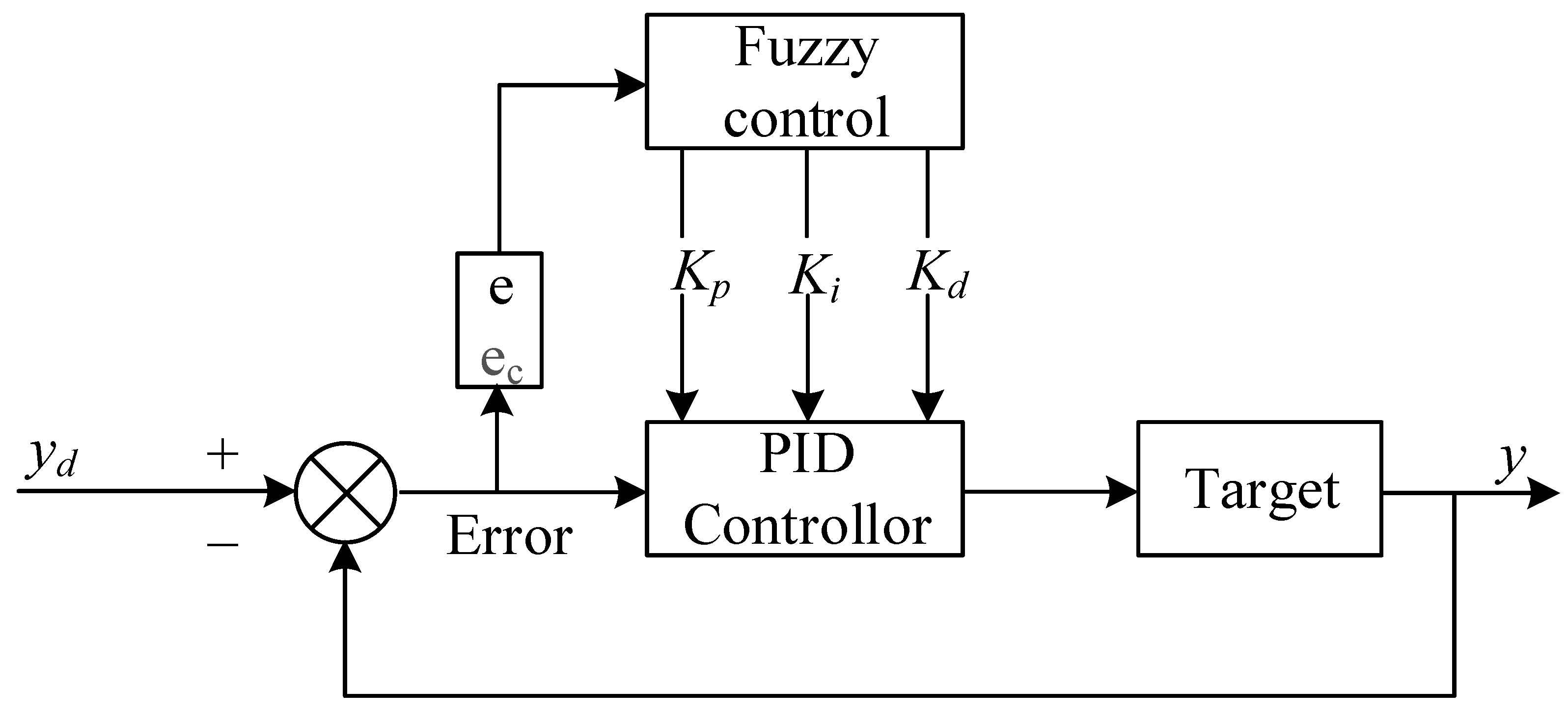
It is more effective by turning the heading than changing speed to avoid collision due to the inertia force of a vessel when a vessel sails in the open sea. Moreover, the protection system of the main engine restricts the drastic change in revolution per minute (RPM). At harbor speed and below, modern merchant ships can reduce their RPM rapidly, but several minutes is need for reducing one RPM when she runs on sea speed. Namely, course alteration is the only choice to avoid collision when ships run at sea speed on the open sea. Autopilot systems have been widely used on ships since the 1960s. This kind of system can provide a ship with the ability to steer the rudder according to proportion integral derivative (PID) control rules if the target course is set. Stand conducted experiments with unmanned submersibles avoiding obstacles in unknown ocean currents by maintaining the minimum safe distance [
27]. Simplified autonomous control is the most effective method for underwater vehicles to execute ACA.
The author proposes an autonomous collision-avoidance decision-making method that conforms to navigation practice and vessel motion characteristics. This method can divide stages, calculate the collision risk index, and determine the scheme of automatic collision-avoidance action for the stand-on vessel. COLREG rules and good seamanship are the basic principles. MMG model, the fuzzy adaptive PID course control system, is employed to predict a vessel’s nonlinear turning motion process. Ship domain is used to decide if the target ship (TS) can pass safely.
The contributions of this article include the methods of finding the timing of the ACA for the stand-on vessel, as well as the last steering time for the OS, which in different stages based on the maximum course changing amplitude. A new CRI model that can be used for the stand-on vessel to take ACA action in restricted water areas is also proposed.
This article is structured into 6 sections, including the introduction. The encounter stage discrimination and the principle of collision-avoidance action are addressed in
Section 2; some necessary basic methodologies are presented in
Section 3;
Section 4 discuss the solution of the last steering point and a mode of collision risk index; The actions of the stand-on vessel in two different encounter situations are simulated in
Section 5; the discussion and conclusion are presented in
Section 6.
2. Encounter Stage and Collision-Avoidance Action Principle
The entire encounter process of two vessels that will eventually collide can be divided into four stages, beginning when the vessels are far apart. This is the so-called “four-stage theory of a vessel encountering process” directed by COLREGs and good seamanship [
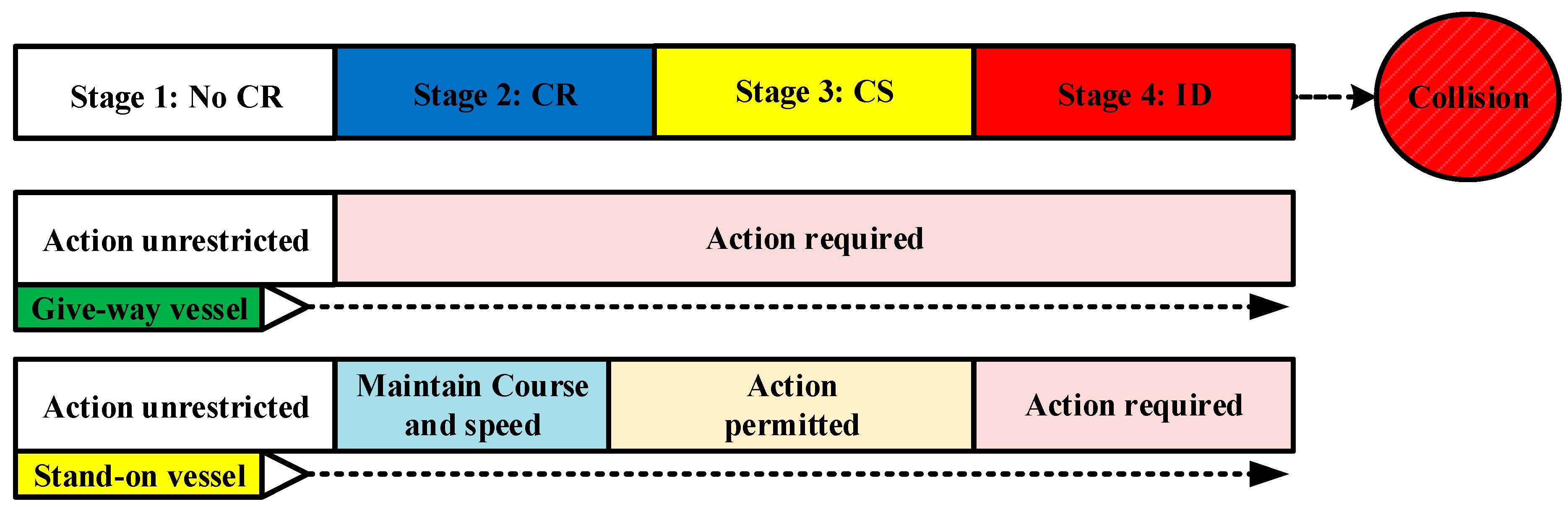
28]. The four stages experienced orderly by both vessels are (1) no risk of collision (CR), (2) risk of collision, (3) close-quarter situation (CS) and (4) immediate danger (ID). Particularly for the stand-on vessel and give-way vessel in the crossing situation, rules 13, 15 and 17 provided the timing and principles of collision-avoidance actions. These connotations of these rules can be summarized as the process shown in
Figure 1.
The collision-avoidance action taken by the stand-on vessel in different stages is different and varies as the encountering situation develops. These actions may include course alteration and speed adjustment. Speed adjustment is nearly impossible when a vessel runs at sea speed in the open water. The reason is already described in Chapter 1. Therefore, the collision-avoidance action scheme of the stand-on vessel includes the course-altering amplitude and timing to take evasive action.
Stage 1: Far distance when the risk of collision stage is not formed.
The collision-avoidance action for the stand-on vessel is unrestricted before the risk of collision stage is formed. The amplitude of the course change should not be too small in the premise of passing safety by rule 8 and good seamanship in sea practice. It ensures TS understands the true intention of the OS and reduces the risk of misunderstandings, which have caused many accidents. The specific value can be set by the captain and is then adopted by the system.
Stage 2: The risk of collision stage is formed, but the stage of close-quarter situation is not formed.
The stand-on vessel should keep her speed and course in the initial stage after reaching the risk of collision stage. Moreover, she shall maintain the most effective way to continuously observe whether the give-way vessel has taken collision-avoidance action as required.
The stand-on vessel is permitted to take actions to avoid collision by her maneuver alone once the give-way vessel does not take appropriate action according to the rules, but not to alter course to port for a vessel on her port side in the crossing situation if the circumstance permitted.
A key problem is when the stand-on vessel is permitted to take collision-avoidance action alone. According to rule 8, any avoidance action taken by a vessel should be substantial. Therefore, it is persuasive that the timing does not appear if small-amplitude manipulation ensures the give-way vessel to pass safely. On the contrary, if the amplitude of manipulation that will ensure the give-way vessel can pass safely becomes so large that the captain of the stand-on vessel cannot tolerate it because he feels it to be dangerous, the collision-avoidance action is still not be taken. This viewpoint can be interrelated to determine the timing of a solo collision-avoidance action by the stand-on vessel. When the distance of two approaching vessels is so close that the stand-on vessel must take a large angle course alteration by the course control system, the give-way vessel is not thought to take the collision-avoidance action as COLREGs.
Namely, the timing of the stand-on vessel being permitted to take collision-avoidance action alone is coming when she finds that a sufficiently large amplitude manipulation must be taken to pass safely. Like the sea practice, the “big amplitude manipulation” by the stand-on vessel alone in the ACA decision-making system at the open sea can be preset as a sufficiently large course-angle alteration in the course control system circumstance because RPM changing is nearly impossible and useless. This angle of the course alteration in this condition may vary according to many factors, such as the scale of ships, traffic environment, etc. The value preset in the system can be input by the captain of a vessel because he has the final words. The autonomous collision-avoidance system will control the course control system to perform the collision-avoidance operation autonomously. In sea practice, it is generally believed that the meaning of “substantial deviation” mentioned in COLREGs is at least 30° or half of the speed reduction. Usually, course alteration is considered the most common method in the open sea. Therefore, the substantial deviation mentioned above collision-avoidance action be set as 30° or greater.
Stage 3: The close-quarter situation stage is formed, but the immediate danger stage is not formed.
In this stage, whatever collision-avoidance actions by the OS are taken, the TS will enter the OS’s ship domain. However, collision will not happen if effective collision-avoidance actions are taken by each vessel. The stand-on vessel is permitted to take collision-avoidance action alone in this stage.
Stage 4: The stage of immediate danger is formed, but a collision has not yet happened.
According to rule 17, the OS must take the most effective action to avoid a collision in this stage, as the collision cannot be avoided by the action of a vessel alone. A substantial turn (90° or more in the course control system circumstance) must be taken in the most effective direction until the distance between the center of two vessels begins to increase.
Fuji (1971) proposed the term “ship domain”, and that a vessel encounter is considered safe if neither ship’s domain is invaded by other vessels [
29]. Most researchers use the term ship domain to indicate the risk of vessel collisions. In the following decades, research in the field of ship domain has further developed [
30]. Goodwin proposed a definition of ship domain as the effective area within a certain range around a vessel that the captain intends to prevent other vessels and stationary objects from entering. With the widespread use of electronic chart displays and information systems (ECDIS) and automatic identification systems (AIS), captains prefer to refer to the actual size and movement characteristics of other vessels to set the appropriate ship domain.
Based on the meaning of ship domain and the stage of the close-quarter situation, the period of the close-quarter situation stage is defined as the period between when the TS will not pass outside the OS’s ship domain to when the OS will collide with the TS, even if the most effective collision-avoidance action is taken by one vessel [
31]. This definition has been widely accepted by the maritime industry. It actually describes the physical meaning of the first moment of the close-quarter situation (FTCS) and the first moment of immediate danger (FTID). The close-quarter situation stage exists between the FTCS and FTID.
In general sea practice, steering full-rudder to avoid collision is the most effective action in the open sea. This method, which is close to human thinking and normal practice at present, is used to calculate the FTCS and FTID in previous studies [
26]. However, the rudder steering angle of an autonomous vessel is decided by the system when she is equipped with a course control system or trajectory control system. The main function of the trajectory control system is to control the navigation track, track planning and navigation alarm, etc. The core part of the trajectory control system is also the course control system.
Therefore, the most effective collision-avoidance action in this situation needs to be defined separately. FTCS/FTID is redefined based on the characteristics of the course control system. FTCS means the timing after which the TS will no longer pass outside the OS’s ship domain even if the most effective avoidance action is taken by the OS course control system. Namely, the TS will pass the outside of ship domain if the same action is taken before this timing. FTID means the timing after which the TS will collide with the OS even if the most effective avoidance action is taken by the OS course control system. Similarly, the TS will not collide with the OS if the same action is taken before this timing.
4. The Situation Factor Model Based on Course Control System
4.1. The First Time-in-Point of Collision Risk (FTCR)
The first step in making a collision-avoidance decision is to identify the type of situation and determine the stage at the exact moment when TSs are approaching. He [
26] introduced the methods to identify the situation. One key issue is to divide the entire encountering process into COLREGs and use good seamanship for the stand-on vessel in the crossing and overtaking situation, provided that a course control system is already installed onboard.
As introduced in
Section 2 (
Figure 1), the first time-in-point of collision risk (FTCR), FTCS and FTID divide the encountering process into four stages. It is a pity that no accurate definition of situation factors (CR, CS and ID) has been not given, although the term of them are mentioned in COLREGs [
23]. Despite the interpretation for situation factors having been discussed for a very long time, the definition of situation factors based on physical process at sea shown in the above studies has been accepted by most researchers. In the traditional simulation calculation for vessels to divide the encounter stage, the course alteration is realized by steering the rudder to hard a port or hard a starboard [
37]. This steering method is more in line with human operation thinking. However, considering the vessel’s steering decision system is required to determine the above-mentioned situation factors for the ACA actions in the ships equipped with TCS or course control system.
The meaning of FTCR can be illustrated combined with the potential collision risk. The potential collision risk means that the TS will eventually not pass outside the OS’s ship domain if the TS and OS maintain their current course and speed. Two vessels begin to be at the risk of collision when the potential collision risk exists, and a certain criterion of TCPA is satisfied at the first time in point. Namely, this moment is defined as FTCR. The determination method of PCR existence was presented in the article [
26]. The captain of the vessel or the MASS designer may set the appropriate data to solve FTCR automatically according to the maneuver performance of a vessel and the navigation environment. This means that this stage starts if the limited conditions of FTCR are satisfied. The captain/officers of a vessel often use the visible range of the navigation lights to judge the encounter situation for two vessels. The COLREGs rule 22 requires that the minimum visibility distance of masthead light and stern light for the power-driven vessel not less than 6 nm and 3 nm. Therefore, the quantitative standards of FTCR can be shown in
Table 1.
4.2. The First Time-in-Point of Close-Quarter Situation (FTCS)
For the model of the FTCS, much advice can be found. Wu and Zheng proposed the term of the last steering point according to the understanding of the close-quarter situation stage: OS and TS are in a close situation when the OS cannot ensure her ship domain will not be invaded by the TS even when collision-avoidance actions measure 90°, or higher angles of course alteration are taken [
38]. The above-mentioned last steering point is similar to the meaning of the FTCS: The OS can prevent the TS from entering the OS’s ship domain by altering the course at any time before this specific time-in-point. On the contrary, after this specific time-in-point, no matter the course alteration made by the OS, her ship domain will be invaded by the TS unavoidably. Obviously, this specific time-in-point is thought to be the FTCS.
A key challenge is finding the FTCS and the minimum course-alteration angle (
) in different situations, which will ensure TS to pass outside of the ship domain, under different timings of the entire encounter situation for the stand-on vessel. The process of the stand-on vessel acting alone in the crossing/overtaking situation is shown in
Figure 6.
In
Figure 6, the ship domain and collision domain are marked in blue and red,
is the distance between the TS and the virtual vessel, which situates in the center of the ship domain of the stand-on vessel, and
is the distance from the TS along the virtual center to the boundary of the ship domain. As the radius of the ship domain in the crossing situation,
is a fixed value but is variably in the overtaking situation.
Figure 6 shows the OS maneuvering process during which TS does not just enter the OS’s ship domain once the TS does not take correct and effective collision-avoidance actions timely as required.
The superscript
represents the time point when the value of the variable is calculated:
where
denotes the real position of the OS in the fixed coordinates system and
is the virtual position of the OS.
,
and
denote the speed, course and LOA of the OS. (
Xt,
Yt),
,
and
denote the position, speed, course and LOA of the TS in the fixed coordinates system.
If OS is the stand-on vessel in an overtaking situation, the equation can be set:
The represents the minimum value of in the entire encounter stage since now if OS alters course to in the time point . This means that the OS takes a collision-avoidance action by turning at the time point .
The TS will enter the OS’s ship domain if . On the contrary, The TS will pass outside the OS’s ship domain if . When it is satisfied, the TS will be tangent to the OS’s ship domain. We can easily conclude that it depends on the independent variables and if the same initial conditions exist between the two vessels.
In the above discussion, once there is a group of and which means course alteration from to taken by the OS since time , will result in that the TS just does not enter the OS’s ship domain. Moreover, a larger course-alteration angle of the collision-avoidance action being taken or taking the same collision-avoidance action before , the TS will pass outside the OS’s ship domain. On the contrary, the TS will enter the OS’s ship domain if a lower course-alteration angle of collision-avoidance action is taken or taken after the same collision-avoidance action . The above angle () is the minimum course-alteration angle of the OS at time .
Many groups of and , which satisfy and ensure the TS to be tangential to the OS’s ship domain, exist in the early stages of an encounter. The OS can adopt different course-alteration angles, which are larger than or equal to , at different times to prevent the TS from entering the OS’s ship domain.
When the distance between the two vessels becomes smaller, the minimum course-alteration angle gradually increases and the number of groups of and becomes smaller. Until a certain moment, the number of groups equals 1, the OS must take collision-avoidance action, and the course-altering amplitude is no less than at once to ensure the TS pass outside the OS’s ship domain. This moment is the FTCS: the TS will enter the OS’s ship domain no matter how much the OS changes its course after this moment.
Whatever if OS changes her course, the position of the OS can be calculated as:
The position of the OS before the time can be obtained by the uniform linear motion equation. When the course control system of the OS receives the command to alter its course, it gives the corresponding rudder command through the fuzzy adaptive PID control method. Afterward, the maneuvering movement process of the OS can be calculated by the vessel’s MMG equations and the Runge–Kutta method when the initial conditions and the rudder angle of a different time are known.
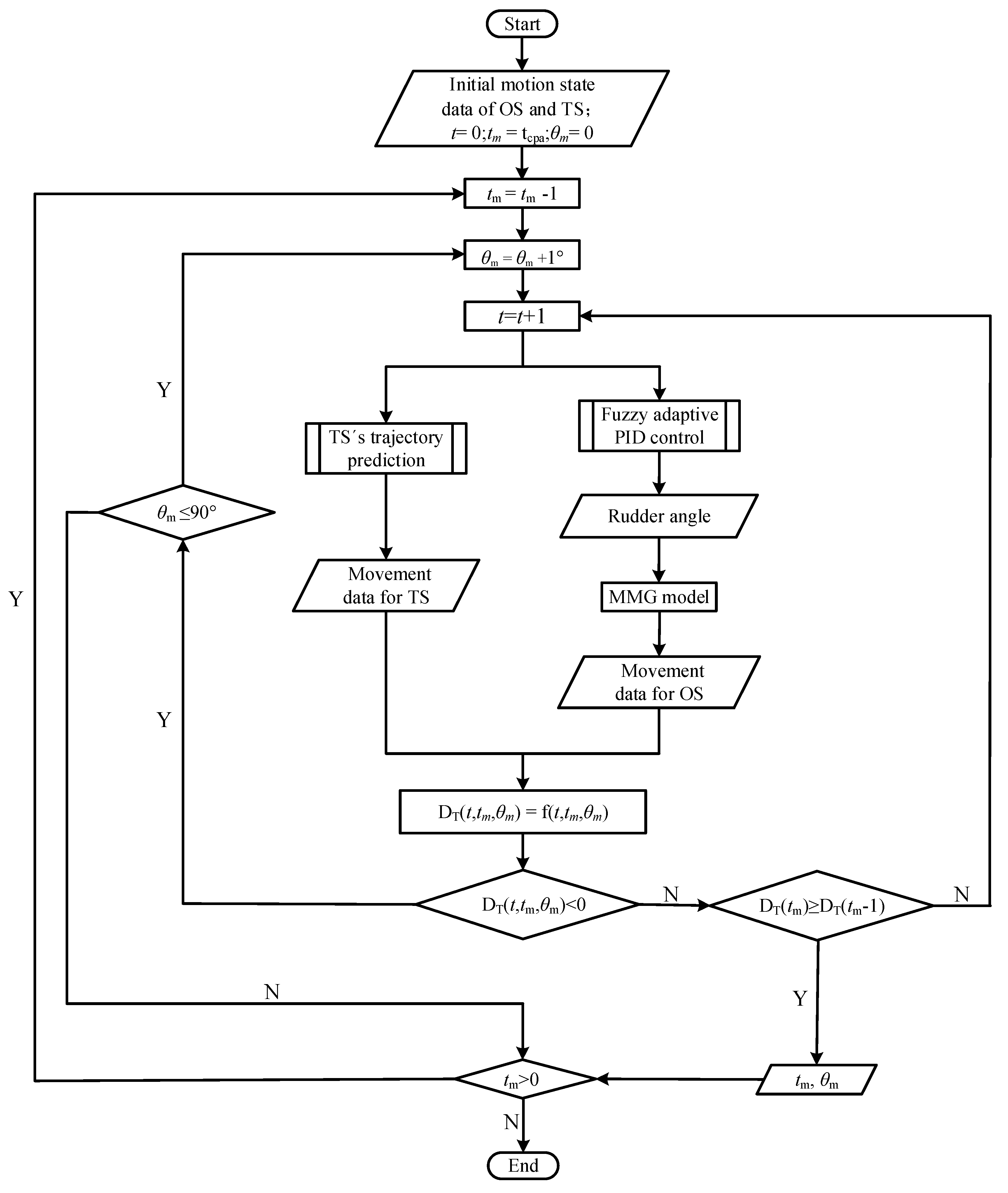
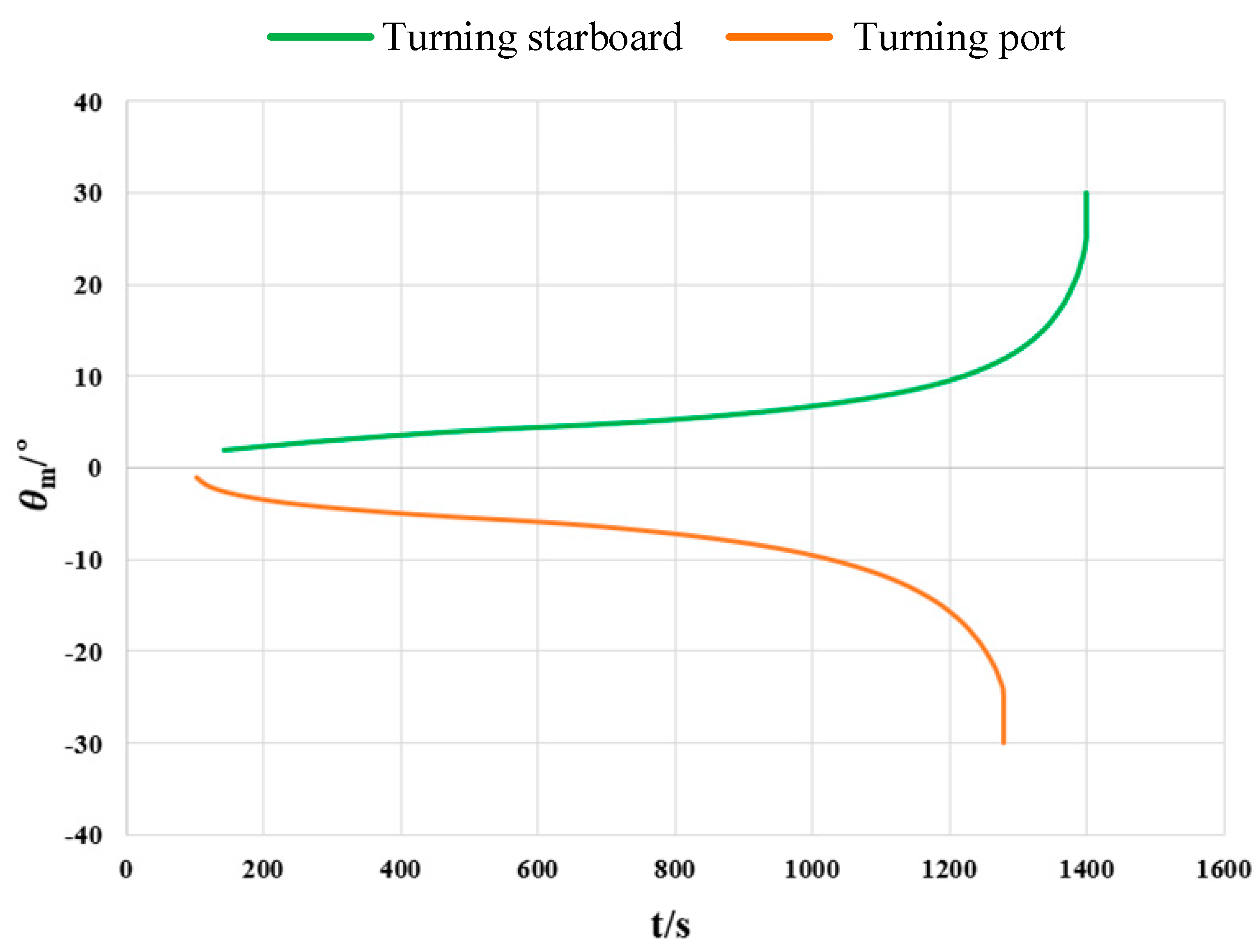
Therefore, the minimum course-alteration angle () under different times for the OS in an overtaking situation and crossing situation can be calculated as follows:
Combining the course to be steered , the fuzzy adaptive PID control, the MMG equations, and initial values of the speeds, courses and positions of the OS during turning can be calculated.
The FTCS of the OS in a crossing situation can be obtained according to the flow of
Figure 7.
Figure 7 shows the numerical method of the minimum course-alteration angle of the OS at different moments in the crossing situation. The OS’s decision-making system can output the minimum redirection angles (
) at different moments. The OS can select a series of corresponding
and
, combined with a certain algorithm, to ensure that the TS does not enter the OS’s ship domain by altering
or more degrees at
. Namely, the OS only needs to alter a small angle when the ACA is taken by turning in the initial stage of forming a collision risk. With the increase of
, the required minimum course-alteration angle that can keep TS pass out of the OS’s ship domain gradually increases until a certain moment when the corresponding
and
of the OS’s ship domain are invaded by the TS, no matter how much the OS takes ACA by changing her course after the above moment. The exact moment is the FTCS.
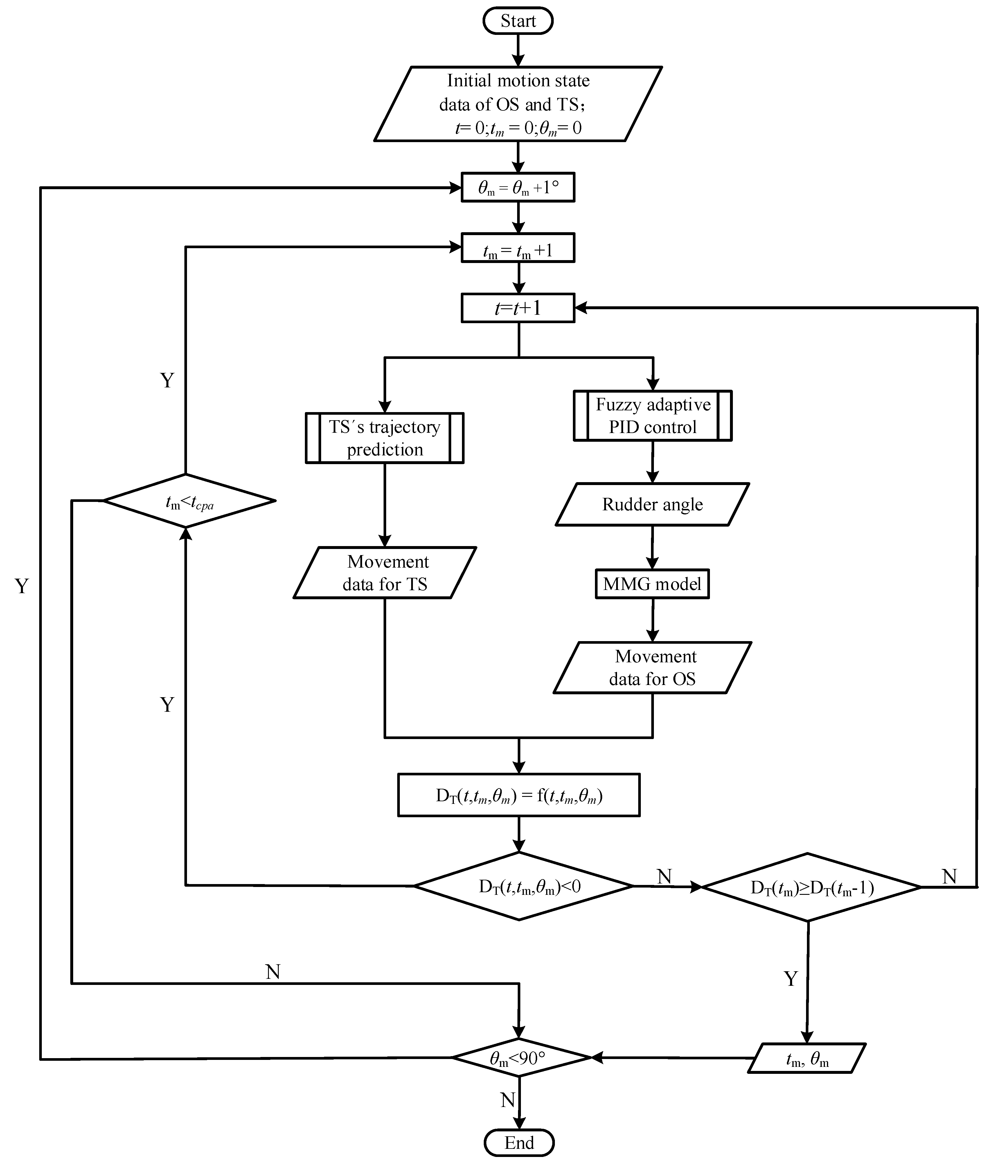
Analogically, the latest action time of the OS under a certain permissible changing course can be obtained according to the flow of
Figure 8.
4.3. The First Time-in-Point of Immediate Danger (FTID)
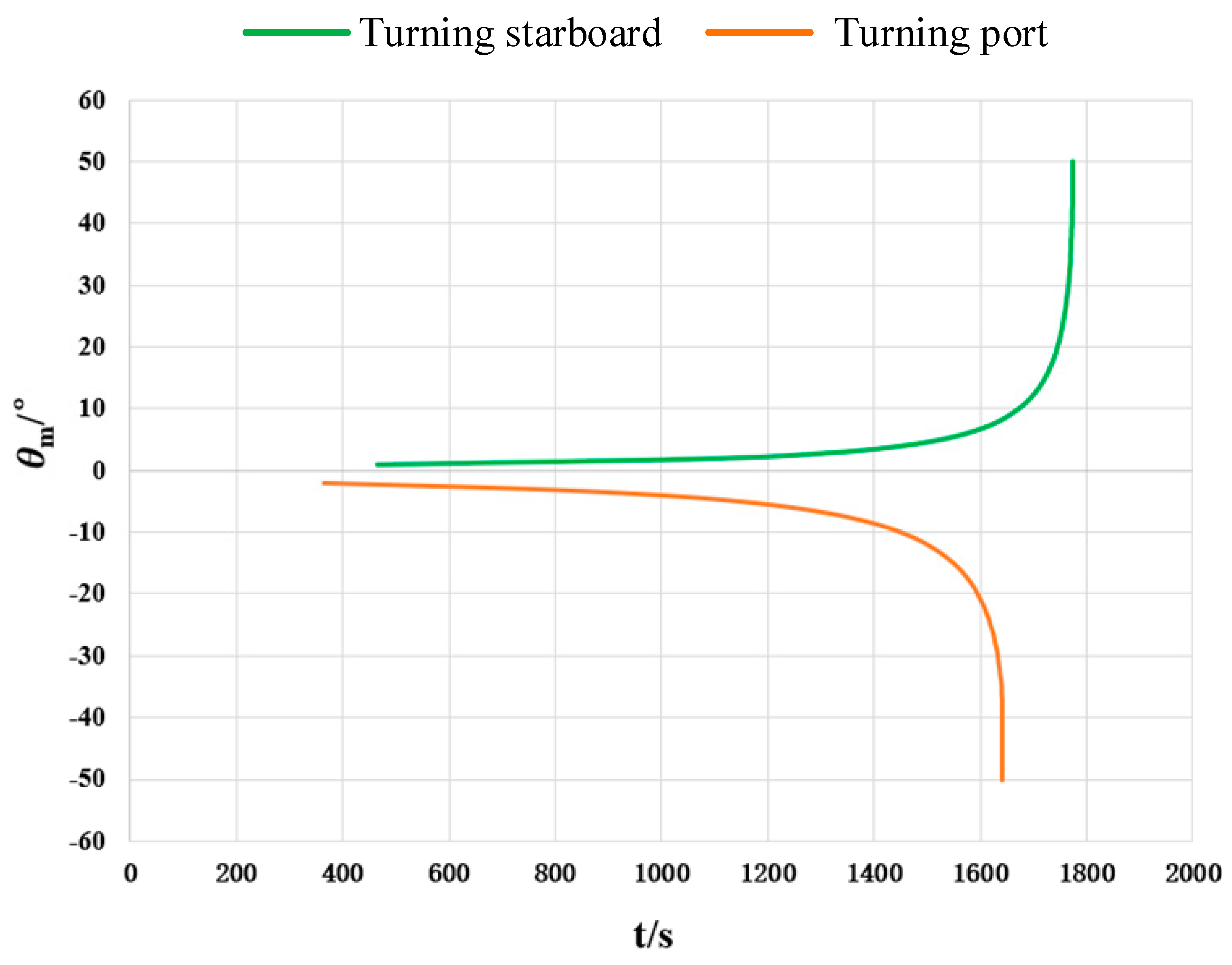
The FTID can be defined as a time-in-point when the OS takes the most effective collision-avoidance action, and the TS is tangent to the collision domain of the OS. The numerical solving method of the FTID can be calculated like the FTCS. The collision domain area shown in
Figure 4 is used to substitute the ship domain used in
Section 4.2.
4.4. The Most Effective Collision Avoiding Direction
When the OS takes collision-avoidance by turning, the correct turning direction, turning time and course-alteration angle are the cornerstones of action to ensure the safety of navigation. The stand-on vessel is entitled to take any collision-avoidance action before CR and after the timing when a sufficiently large amplitude manipulation must be taken that the TS can pass safely.
Rule 17 of the COLREGs stipulates the direction of action of the stand-on vessel in a crossing situation. The stand-on vessel should not alter to port in a crossing situation if the situation allows. However, other stand-on vessels should take the most effective collision-avoidance actions as per COLREGs. For vessels running on the open sea, course alteration is the only way, as described in
Section 1. They can only decide the timing, amplitude and direction of the course alteration. It is essential to find a method that solves the more effective collision-avoiding direction between port and starboard in the course control system circumstance.
The minimum course-alteration angle at different times or the latest timing under the certain course-alteration angle that will ensure the TS can pass outside the ship’s domain or the collision domain can be calculated by the methods presented above. Based on the results of these calculations, two methods can be used to determine the most effective direction when two vessels are approaching.
Method 1: Given the minimum course-alteration angle of the OS to ensure safe passing to port and starboard are and respectively, the direction of the most effective collision-avoidance action can be determined by comparing the values of and . Turning to starboard will be the most effective direction of action when exists.
Method 2: Given the course-altering amplitude to ensure safe passing is fixed, the latest steering time and for the OS to turn port and starboard can be calculated, respectively. Similarly, if is less than , it turning starboard is the more effective direction for the OS because there is more time for the OS to avoid a collision.
4.5. The Decision-Making Model Based on Collision Risk Index (CRI)
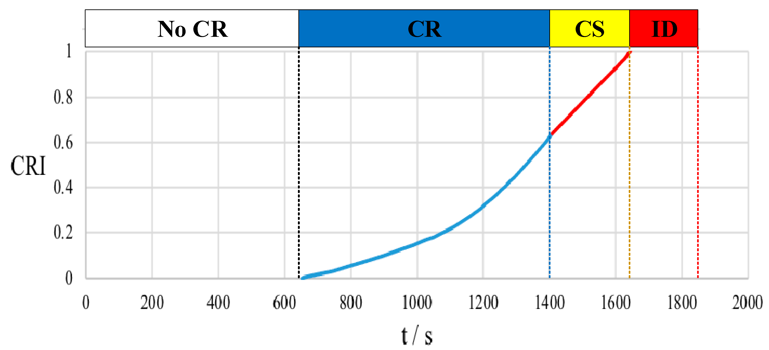
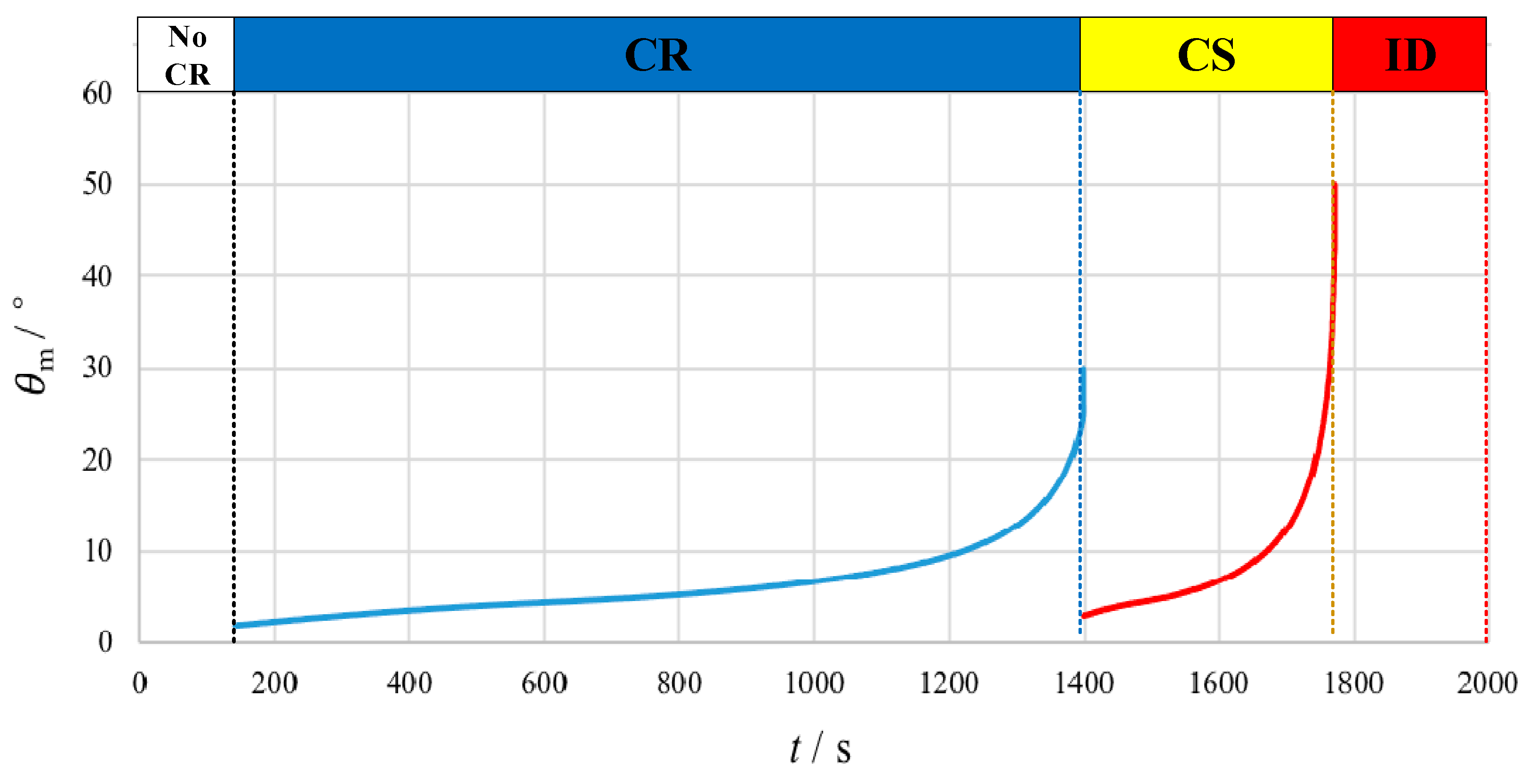
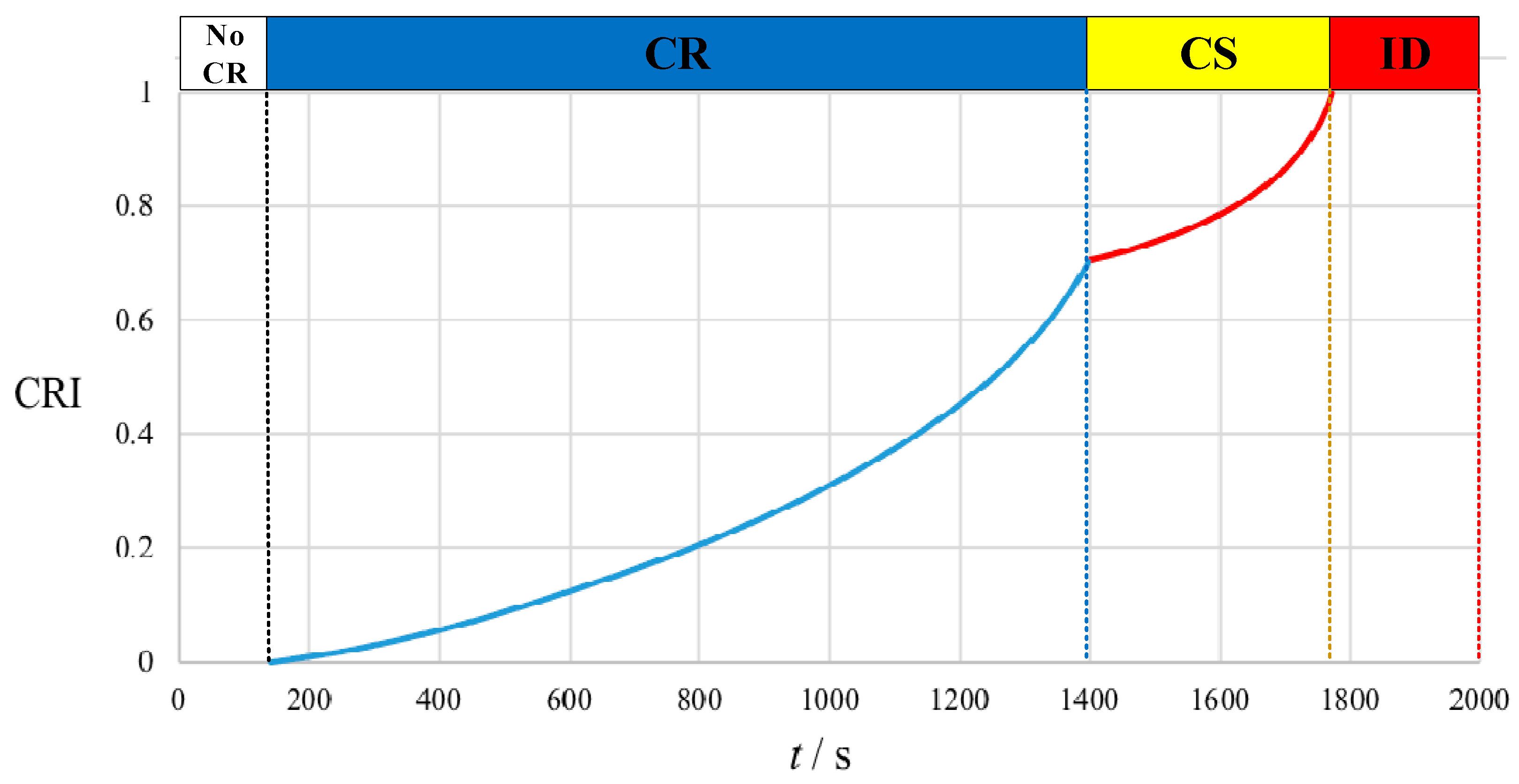
Collision is one of the main factors threatening the safety of intelligent vessels. It is vitally important to take the collision-avoidance action as required. However, combined with the four-stage theory in Chapter 2, the rules only vaguely point out that the stand-on vessel can take the collision-avoidance action when it is obvious that the give-way vessel does not take any actions following the COLREGs. Therefore, it is necessary to build a CRI model for the stand-on vessel to quantify the timing when the stand-on vessel can be permitted to take the collision-avoidance action.
CRI describes the risk level of the encounter situation and the urgency of taking the collision-avoidance action. The effect factors of CRI include the TCPA, DCPA, relative position, movement characteristics, physical dimensions of the hull, speed, ship domains, surrounding environment, etc. Based on using the minimum course-alteration angle to quantify ship maneuvering difficulties at different times, a CRI model for the stand-on vessel is presented as follows:
where
is the time step;
is FTCR;
is FTID;
is the minimum angle of all the course-alteration angles to avoid a collision at the time
.
This CRI model combines the factors of the minimum course-alteration angle in different timing during the entire risk of collision stage and close-quarter situation stage period. It can reflect the mental burden of seafarers about the ship collision risk. A larger CRI indicates a greater risk of ship collision and a greater urgency of ship collision-avoidance maneuvering; a smaller CRI shows that the OS has more time and a larger feasible course alteration range to take the collision-avoidance action. The value of CRI ranges from 0 to 1 and increases with the time going and minimum course-alteration angle rising. While “0” means there is no collision risk, even if the TS is very close to the OS, “1” means that collision cannot be avoided by the action of the OS alone.
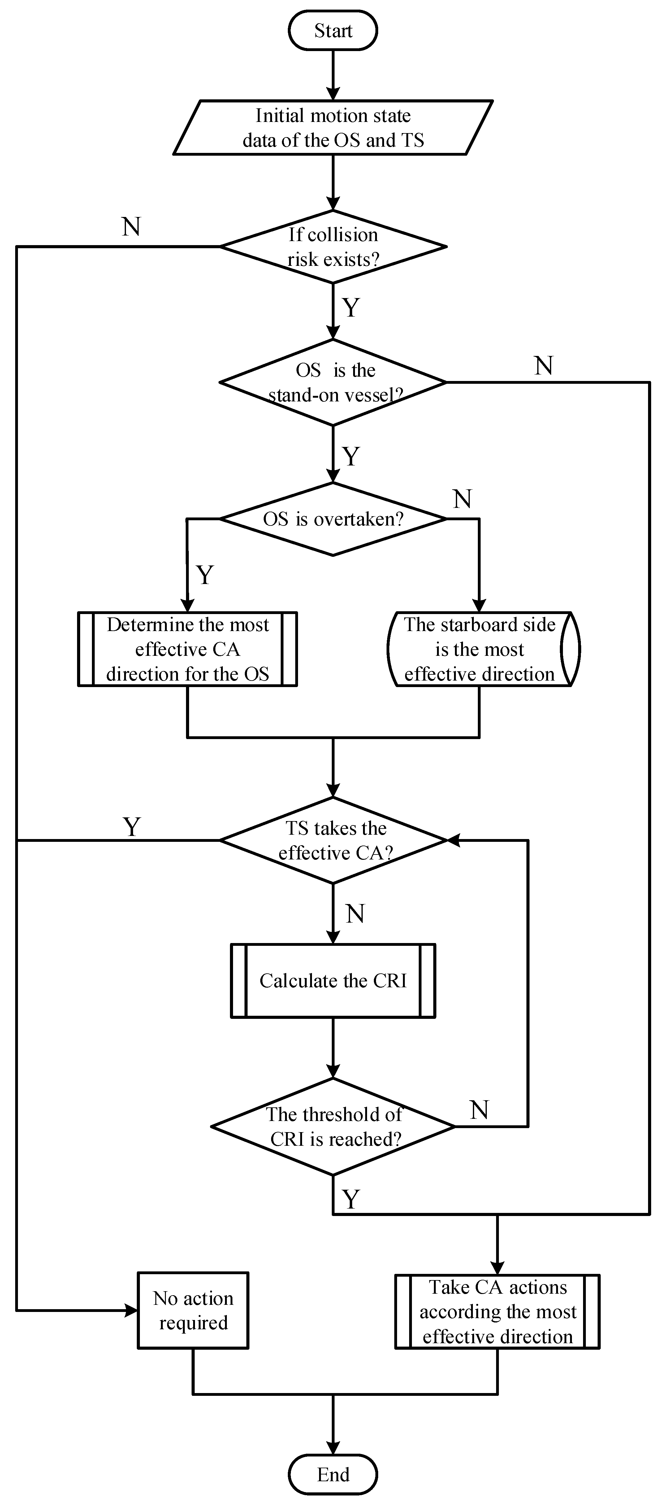
The CRI model is consistent with the seafarers’ judgment of ship collision risk and can be applied to quantify the collision risk from FTCR to the FTID. Based on the CRI model, the decision-making method of the ACA for the stand-on vessel can be shown in
Figure 9.
Based on the data of the initial motion state of the OS and TS, it can be judged whether the OS is a stand-on vessel or a give-way vessel when the collision risk exists in the encounter according to the COLREGs. If the OS is the give-way vessel, it should take collision-avoidance actions as required; if the OS is the stand-on vessel and the TS has taken effective actions to avoid a collision, the OS should keep its present course and speed. If the OS is the stand-on vessel and the TS does not take effective actions, the OS should determine the most effective collision-avoidance action direction, then take collision-avoidance actions when the threshold of the CRI is reached. Based on the CRI model, determine the timing and scheme of the ACA to enable the two vessels to pass safely.


 ,
, 


