1. Introduction
The oil and gas industry is one of the largest economic activities globally, which is also known as the world’s largest energy producer. The vast and complex networks of offshore pipelines are used to transport oil and gas to different areas. Underwater natural gas pipelines were installed in the late 1900s and are still in use [
1]. With the growth and aging pipeline network, corrosion and leakage are more likely to occur, and the frequency of leaks reported in recent years is more than twice the previous rate [
2].
Due to the potential risk of the gas pipelines polluting leaks into marine environments, the continuous inspection of pipelines and the ability to determine the exact gas leak is of particular importance. The most important purpose of underwater pipeline leak detection is to reduce environmental pollution, conserve valuable energy resources, prevent unpleasant disasters, and ensure safe operation of the pipeline. According to extensive research, most submarine pipeline failures are due to equipment failures, construction defects, corrosion, weather, external interference, and harbor damage [
3]. The impact of factors varies in different areas, and severe consequences can be influenced by several factors.
Different methods are available and are being developed for subsea pipeline inspection. These can be generally categorized into internal (or software-based), external (or hardware-based) methods, and Transient Test-Based Techniques (TTBTs). Transient Test-Based Techniques are used for leak detection and evaluation based on transient pressure waves properties, where pressure waves are injected in pipelines and the leak is detected by considering partial reflection of pressure waves in interaction with a leak [
4,
5]. Internal leak detection methods are costly and can fail to locate gas leaks and operations on long pipelines. The success of external methods, except for the acoustic method, depends on the water turbidity and flow, which are also expensive and unable to locate gas leaks in most cases [
6,
7].
Environmental characteristics and high absorption of visible light in seawater have made it difficult and sometimes impossible to inspect the underwater pipeline by optical cameras; the acoustic methods are generally considered as the most efficient means with a wide coverage range for underwater pipeline inspection and leak detection. When a gas leak occurs underwater, gas bubbles are produced that generate acoustic signals. Underwater acoustic signals propagate easily, where a small leak can generate a powerful acoustic signal [
6,
8].
The high acoustic impedance contrast between the gas bubbles and surrounding water as well as long-range capabilities of sonar make the sonar system a useful tool for the seabed pipeline inspection. Common acoustic methods include multibeam sonar [
9,
10], side-scan sonar [
11], and passive sonar [
12].
The performance of sonar systems depends on the acoustic scattering characteristics of gas bubbles in the sea environment. Therefore, accurate computation of gas bubble acoustic scattering signals to correctly detect leak signals from other received acoustic signals is the main challenge in all types of sonar systems. Current methods rely on the ability of an expert operator to scrutinize the data, additional equipment, and long observation time in the case of stationary systems, to achieve reliable detection [
13].
Recently, Synthetic Aperture Sonar (SAS) has been proposed as a powerful tool for inspecting pipelines and hydrograph surveys. This technology can collect accurate information and provide high-resolution images of the seabed over the full of the swath in which the azimuth resolution is independent of frequency and range. Therefore, SAS technology using Autonomous Underwater Vehicles (AUVs) can be used as an alternative solution in pipeline inspection operations with real array sonar systems based on Remotely Operated Vehicles (ROVs), which is time-consuming and costly.
In this paper, a new leak detection method is proposed based on a gas bubble scattering model using SAS technology. In the proposed method, a coherent combination of gas bubble acoustic scattering in synthetic aperture range migration is used to accurately model gas bubbles in different sizes and ranges. The pipeline acoustic scattering is computed using the Texture Element Model (TEM) [
14], which is an accurate and computation-less model for computed acoustic scattering of underwater targets, essentially in SAS systems processing. Consequently, the proposed method can distinguish gas leak signals by collecting accurate scattering information in one pass only. The proposed method can be used effectively to improve leak detection methods and facilitate automatic pipeline inspection to reduce environmental and economic consequences. The main objectives of the paper can be summarized as follows:
Subsea pipeline leak detection is very important in terms of environmental economics. In this paper, an effective method is proposed for gas leak detection based on SAS system technology.
Due to the importance of the underwater gas bubble acoustic scattering in leak detection, a new method is proposed for accurately calculating gas bubble acoustic scattering using a combination of the spherical scattering model to solve the Helmholtz equation in spherical coordinates with SAS technology.
Synthetic aperture sonar systems are introduced as the best tool for accurate and fast leak detection, and for the first time, a simulation of SAS systems for underwater pipeline leak detection is presented.
In the proposed method, a coherent combination of gas bubble and pipeline scattering fields at multiple scattering angles and migration ranges along synthetic aperture is used for accurate gas bubble modeling at different sizes and ranges in the marine environment.
The proposed method, based on a coherent combination of gas bubble modeling with SAS technology, is able to prominently distinguish leak signals compared to non-coherent real array methods.
The proposed method can effectively improve automatic leak detection algorithms and reduce costs related to pipeline inspection.
The rest of the paper is organized as follows. In
Section 2, an overview of sonar technologies in pipeline surveys and gas leak detection is presented. A brief description of the SAS systems and gas bubble acoustic scattering characteristics in the marine environment are presented in
Section 3.1 and
Section 3.2, respectively. The proposed leak detection method based on the combination of gas bubble acoustic scattering modeling with SAS technology is explained in
Section 3.3.
Section 4 presents the results of the simulation and comparison of the proposed coherent method with the non-coherent method, and the conclusions and future work are summarized in
Section 5 and
Section 6, respectively.
2. Related Work
Today, seabed pipeline network installation and distribution at long distances are essential. Due to increasing age, corrosion, and external factors, continuous inspection and leak detection of the seabed pipeline are of particular importance in terms of safety and the environment. Pipeline leak detection from sources such as small leaks and pinholes are very important because they can go unnoticed for long time periods, leading to economic losses and environmental damage [
15].
Most offshore gas pipelines around the world are between 30 and 100 years old [
16]. Seabed gas pipeline leak detection methods can be categorized as internally and externally based. Internal leak detection methods use software systems to continuously check the pressure, temperature, and gas flow velocity in the gas pipeline, while external leak detection methods are based on hardware sensors. Due to high cost and internal method inefficiency in leak localization and long pipelines, the use of hardware sensors to detect and localize leaks is more common [
6,
17].
An accurate subsea pipeline inspection requires collecting correct information for reliable processing. Due to light absorption and high salinity of the marine environment as well as the acoustic impedance difference between gas bubbles with seawater, the use of acoustic sensors is the best and most common method for seabed pipeline inspection and leak detection operation, which are provided as passive and active sonars.
The ability to detect underwater gas leaks using sonar technology has been around for a few decades. In the first study in 1974, Sweet et al. showed that underwater high-resolution acoustic profiles could be used to detect bubbles in the ocean environment. Since then, a wide range of studies has demonstrated the acoustic ability to detect gas leaks [
18].
In 2018, Yegit et al. used a passive acoustic-based system to detect acoustic signals and locate the leak holes remotely [
12]. The passive sonar contains a hydrophone to receive propagated acoustic signals in the water structure and detects a gas leak after processing. Despite research, the signal processing challenge in leak localization as well as background noise, acoustic shadow, and leakage pressure drop in the leak path can affect passive sonar performance [
17].
In general, in an environment with high background noise, active sonar systems are preferred due to their ability to work with the selected frequency. Due to advantages such as appropriate size, high resolution, and high signal-noise ratio (SNR), active sonars have become efficient systems in gas leak detection, where the passive hydrophone array can never compete with active system resolution or sensitivity [
19].
In 2013, Wendelboe et al. proposed the use of Multi-Beam Sonar (MBS) for leak detection in offshore oil and gas facilities. They used a combination of active and passive multi-beam sonar modes to detect and locate leaks. In conventional active mode, a leak is detected from the backscattered field, and in passive mode, from a received signal from external sound sources. They showed that an active sonar mode is a powerful tool for seabed leak detection [
10].
In 2011, Midtgaard et al. introduced an automatic detection and tracking method of subsea oil and gas pipelines based on data collected by side-scan sonar [
20]. In 2013, Eriksen introduced the use of high-frequency multiple-beam sonar as a useful tool for detecting and tracking hydrocarbons. This showed that active sonar systems are a useful technology for inspection and can detect leaks in seabed infrastructure as well as dangerous critical areas with minimal false alarms [
21].
In 2017, Zhang et al. used a multiple beam sonar to collect acoustic data from pipeline gas leaks. After forming acoustic images, removing background noise, then using mathematical morphological processing, gas bubble characteristics were extracted from the sequence of images [
22].
In 2015, Pailhas et al. developed a multi-layered cylindrical acoustic scattering theory to accurately model echoes from a complex pipeline structure. Inspection operations were performed using sonar technology and acoustic scattering theory on simulated and real data to detect pipeline obstruction. They showed that wideband sonar technology is an effective tool for pipelines obstructions inspection and detection remotely [
23].
In the latest decades, sonar technologies such as multiple beam sonar and side-scan sonar have been widely used as a suitable acoustic tool in subsea pipeline leak detection and inspection. A precise underwater pipeline inspection requires accurate information from the seabed. In most mentioned sonar systems with increasing beam width and range, accuracy and along-track resolution are significantly reduced and acoustic image resolution is dependent on the frequency. Therefore, operation range and coverage area rate are limited in these systems [
8,
10,
16].
In 2019, Marcon et al. provided a multi-beam sonar system to detect and track gas bubbles. The sonar system was set to collect data at specified intervals over several years to control greenhouse gases. Sonar design and the post-processing steps required for data processing were discussed [
24].
Recently, SAS systems have been proposed as powerful tools for pipeline inspection and bathymetry. This technology is able to collect accurate information from the subsea on the full extent of the swath and produce high-resolution images independent of range and frequency. The SAS system provides a higher area of coverage rate inspection than real aperture sonar systems.
In 2015, Fernandes et al. proposed a three-step operation to inspect oil and gas pipelines. The first step involved defining and identifying the pipeline. In the second step, an AUV-based SAS system was used for an initial inspection to locate pipelines and large damages, and the third step included a special inspection with a high-quality camera at a short range (3 to 5 m) of the pipeline to detect small damages [
25].
Hagen et al. proposed a new concept for pipeline inspection using a SAS system. They showed that the SAS system could significantly improve the data received in terms of quality and area coverage [
26].
In 2020, Nadimi et al. proposed a new acoustic scattering model from the underwater targets called Texture Element Method (TEM), which efficiently improved the computational cost and time relative to other well-known acoustic scattering models. The TEM model calculated acoustic scattering fields based on an efficient non-uniform discretization method using statistical and structural information of target surface texture and led to realistic modeling of underwater targets, such as pipelines, in different SAS systems. The TEM model can be used efficiently in various underwater applications as pipeline modeling in leak detection in different SAS systems [
14].
Although leak-scattered acoustic waves can significantly help with early leak detection, background noise can easily affect actual leak waves. In most of the methods mentioned above, to achieve an accurate detection and inspection the sonar system with additional equipment, denoising algorithms, expert operators, or a combination of other sensors must be used. However, in this paper, a new method of a coherence combination of gas bubble acoustic scattering using SAS technology is proposed in which precise modeling of gas bubbles in the SAS system leads to accurate leak detection without the need for additional equipment and improves the SAS system performance in automatic leak detection.
3. Problem Formulation
3.1. Synthetic Aperture Sonar
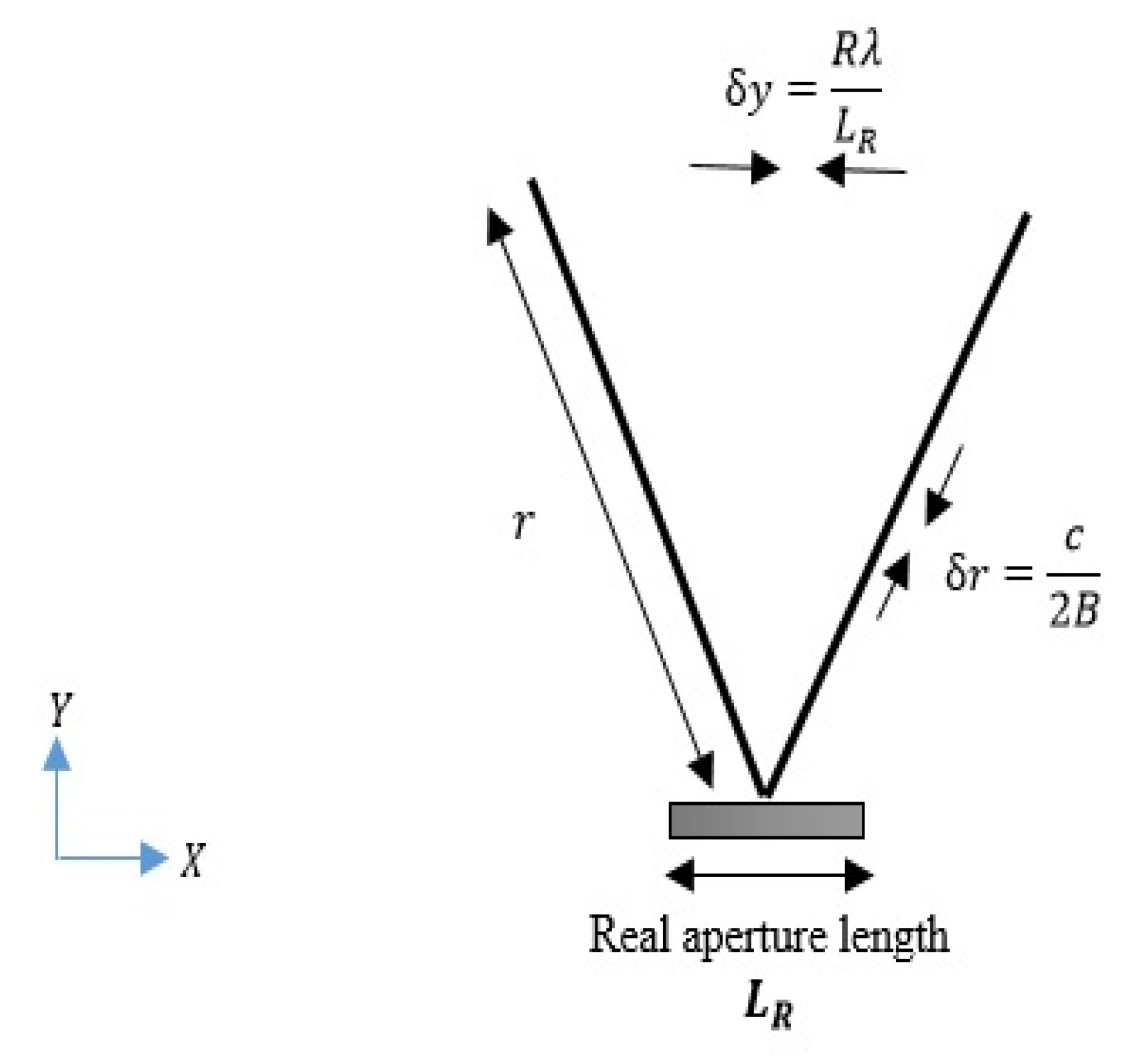
The Synthetic Aperture Sonar (SAS) system is an improvement on traditional sonar, which produces high-resolution and frequency-independent acoustic images by combining successive pings coherently along a known track. High-resolution imaging in real aperture sonar is obtained by increasing acoustic frequency or increasing aperture length. Due to more absorbing of acoustic energy at higher frequencies, increasing acoustic frequency limits achievable range in the ocean. Besides, the use of a long aperture is expensive and practically impossible [
27,
28]. The geometry and basic parameters of the real aperture sonar are shown in
Figure 1.
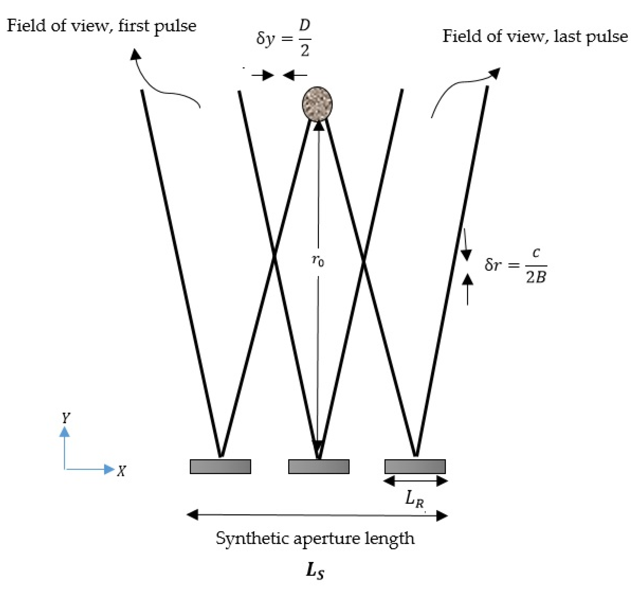
SAS technology nature is very similar to Synthetic Aperture Radar (SAR); by moving the sonar platform forward and collecting multiple pulse-echoes, a longer aperture is synthetically formed, such that sonar along-track resolution is improved. The SAS system can produce accurate seabed models by detecting echo entry angles from the seabed. Therefore, SAS has a multi-use technology with good potential in various fields such as offshore oil and gas pipeline installation and inspection, imaging, mapping, deep-sea mining, and underwater archeology [
26,
29,
30].
Figure 2 shows the synthetic aperture geometry in the SAS system.
Real array systems focus on separating collected data and process the echo from each ping individually, while the SAS system focuses on data composition instead of distinguishing. Moreover, the SAS system surveys wider areas than the real aperture system. The SAS system can be used as an alternative to video recording and review operation, which is a time-consuming part of AUV-based pipeline inspection projects. An AUV-based SAS system with a modern and synthesized data collection method saves time, which is impossible in traditional sonar systems.
3.2. Gas Bubble Acoustic Scattering
One of the most important parameters in the sonar equation is accurate target strength calculation, which requires an actual model of the target acoustic scattering. A target scattering signal is achieved from the interaction of sent/received signals between active sonar and target. The acoustic scattering problem of an underwater closed target influenced by an acoustic signal involves solving the Helmholtz equation [
31], Equation (1), which can be represented as a series of spherical functions. Therefore, (gas) bubble acoustic scattering can be considered as a (full of gas) sphere scattering.
where,
,
, and
are Laplacein operator, wave number, and wavelength, respectively,
is incident acoustic pressure and
is scattering pressure.
Consider a sphere in free space is influenced by an incident acoustic pressure
with a wavelength
, a general and accurate solution for calculating the sphere acoustic scattering can be expressed as [
32,
33]:
where
is the range,
is the scattering angle,
is the spherical Hankel function of the first kind, and
is Legendre polynomial of order n. The coefficient
is determined by the sphere boundary conditions.
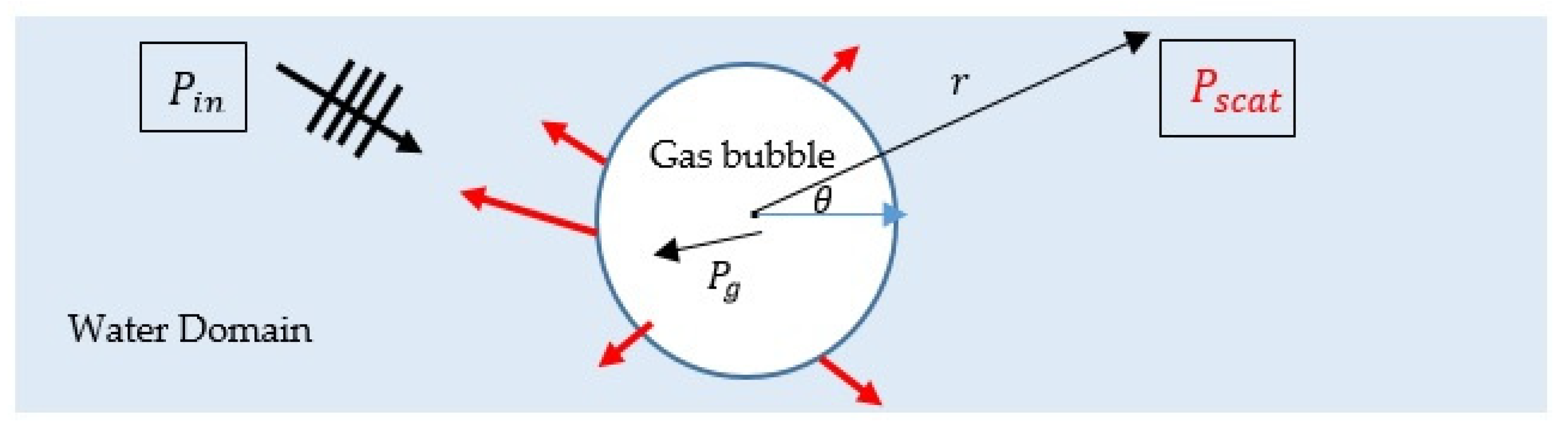
In boundary conditions of a gas-filled sphere, the sum of incident acoustic pressure
and scattered acoustic pressure
is equal to gas pressure inside sphere
, Equation (5). The acoustic scattering geometry of a spherical gas bubble is shown in
Figure 3. Scattered pressure from a gas-filled sphere with radius
(i.e., gas bubble) is calculated as Equation (6) [
34].
where
is sound speed inside the gas-filled sphere,
is sound speed inside water,
is density contrast of water
to gas
. The
and
are derivatives of the spherical Bessel and Hankel function of the first kind, respectively.
3.3. The Proposed Method
When an underwater pipeline gas leakage occurs, gas bubbles are produced. Some of these gas bubbles may reach the ocean surface and enter the atmosphere, and some may be absorbed by the ocean’s ecosystem and make irreparable risks to the environment. Early seabed leak detection is very important because it is easier to resolve a small leak than a large leak. Moreover, to prevent unpleasant events and environmental pollution to preserve this valuable energy source, the leakage must be detected. Each gas leak bubble produces a sound wave; the smaller bubble, the higher its resonance. Sonar systems use the gas bubbles’ acoustic scattering to detect the leaks. The main challenge in sonar systems leak detection is an accurate distinction of leak signal from noise.
In this section, the proposed method will be explained to show how an accurate leak detection using SAS system technology and coherent combination of the gas bubble acoustic scattering will be achieved.
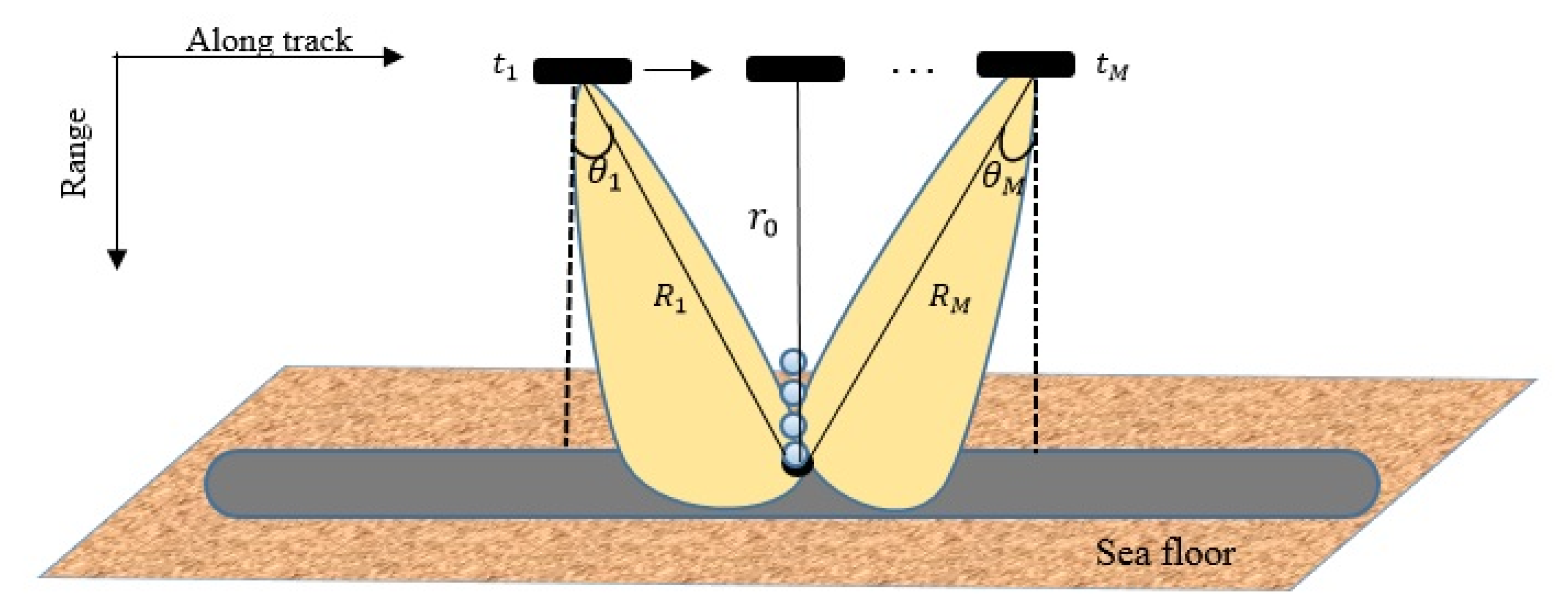
Figure 4 shows the data collection geometry of the proposed method. Consider a SAS with an element length
(as monostatic) moving along track. The platform stops in a set of
positions at equal distances. During each stop, a pulse will be transmitted to the target scene in
of range migration (a set of different ranges between one target and sonar sequential positions) and the echo is captured at
of the received time series. Sending and receiving pulse/echoes are sequentially repeated M times until the target finds the sonar field of view. The time series
of the received echo in the sonar at different ranges
is calculated as stated in Equations (7) and (8) [
35,
36].
where
are the coordinates of the different sonar positions,
is a target position,
is the target range from the sonar at the point of closest approach that customarily called the broadside range, and
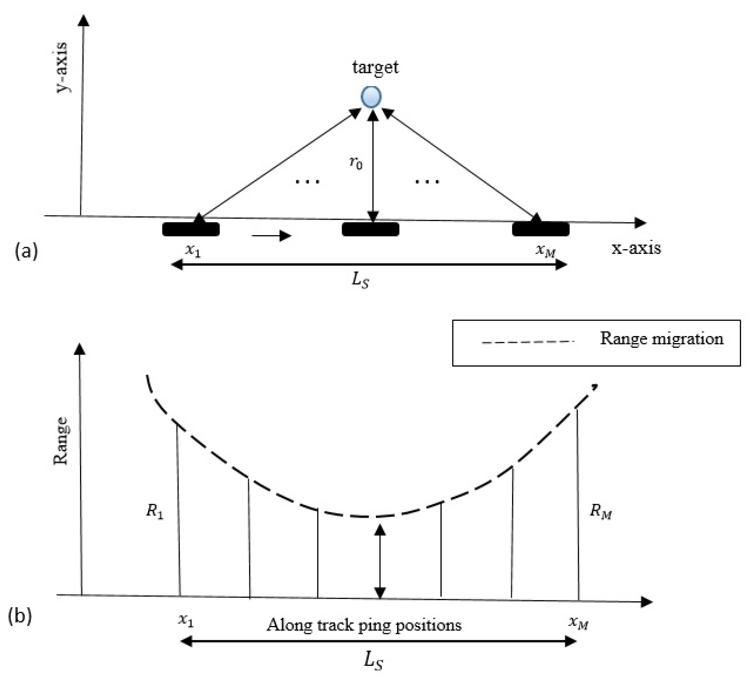
is a range migration that is defined as a set of different ranges between one target and sonar sequential positions. In the concept of a synthetic aperture, a fixed target within the field of view sonar moving in a straight path will exhibit a range migration. The range migration of a target as it passes through the field of view sonar in
time series is shown in
Figure 5. By recognizing the range migration, it is possible to effectively process the ensemble echoes returned from one target from separate pules in sequential time series
. In this paper, it is assumed that the sonar platform moves sequentially at a constant speed and sonar platform and targets are stationary during transmission and reception, so there is no Doppler shift present in the target echoes.
When a leaking gas bubble appears in the sonar field of view, the bubble acoustic scattering in the sonar receiver direction
is calculated using Equation (6). While the gas bubble is in field of view of SAS different positions
, the acoustic scattering
at SAS positions
with ranges
and scattering angles
in a time function
is calculated and stored by Equation (9).
To do this, the range migration must first be determined. After collecting the bubble acoustic scattering at
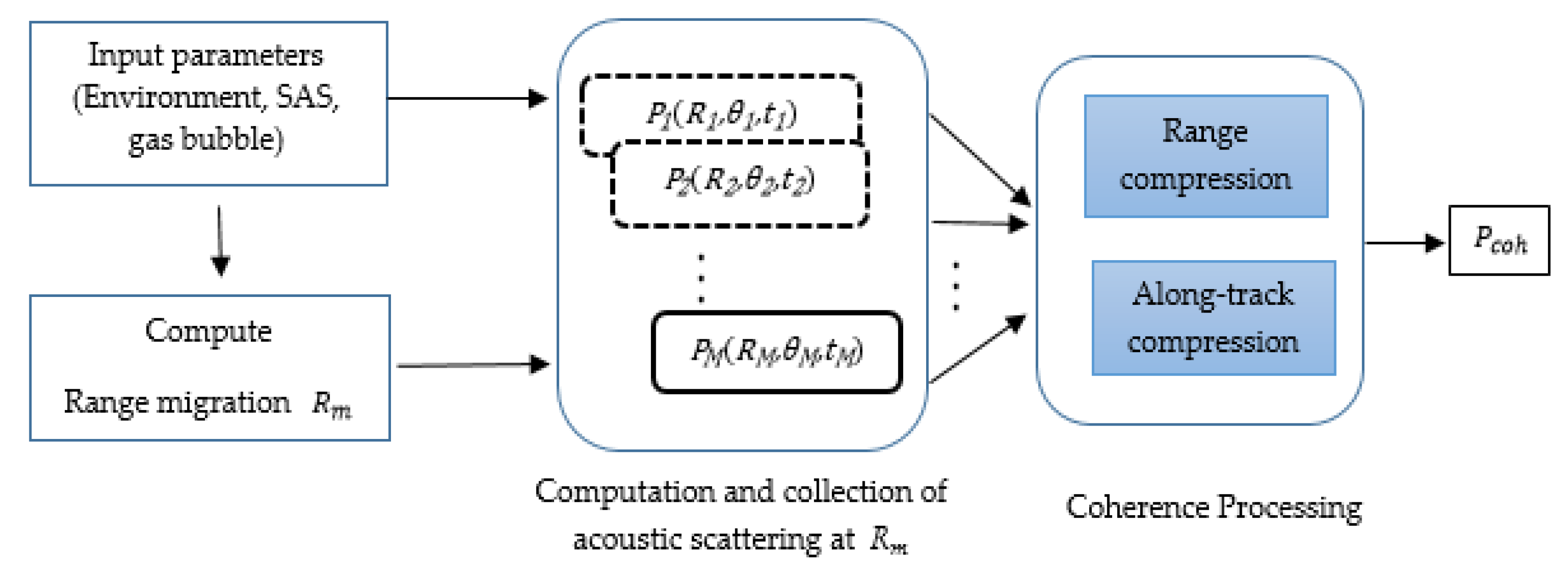
and obtaining a set of acoustic reflections fields of the bubble at different scattering angles as Equation (9), instead of one scattering field of the bubble in real array sonar systems, they are coherently combined to achieve the ensemble echoes and a reliable bubble scattering
. The proposed method diagram for combining different acoustic scattering fields of one bubble is shown in
Figure 6.
After calculating the acoustic scattering fields obtained from transmitted pulses at M different positions in the sonar motion path, the scattering fields are stored as a function of scattering angles, range migration, and time series. Then a pulse compression operation is performed on the scatter signals in each time series to reduce the impact of the side lobes. Finally, considering the phase difference at the received echoes using along-track compression, the scattering fields are coherently added/combined and an accurate bubble scattering field is obtained.
Due to the combination of scattering fields at different scattering angles of the sonar, the proposed method is able to accurately distinguish the gas bubble from the background, where it can detect gas bubble signals in just one pass. The proposed method can potentially be used in real-time leak detection systems.
4. Results
To investigate the proposed method, a part of the natural gas pipeline on the seabed with a SAS system platform at depth
of the pipeline was considered. The simulation parameters required for the experiment are given in
Table 1. It is assumed that the SAS system platform with a monostatic L-length transducer moves in a linear path above the pipeline at a constant speed and by transmitting acoustic pulses in M different positions along the path with equal distances in the different ranges
illuminates the target scene. Scattering fields are collected and stored in a backward direction at the different scattering angles
.
Data collection by the SAS system is considered stop-and-go, so the platform’s movement can be ignored during pulse transmission and echo reception. Leak gas bubble detection is achieved by identifying the range migration and coherent processing of the received echoes at range migration in different scattering directions. To evaluate the proposed method accuracy, the gas bubble acoustic scattering was compared with the real aperture method. For more investigation, the experiments were performed in several steps, including comparison of different gas bubble sizes, comparisons at different depths, and comparisons in the presence of a pipeline acoustic scattering as the background noise. These results are shown in the following subsections.
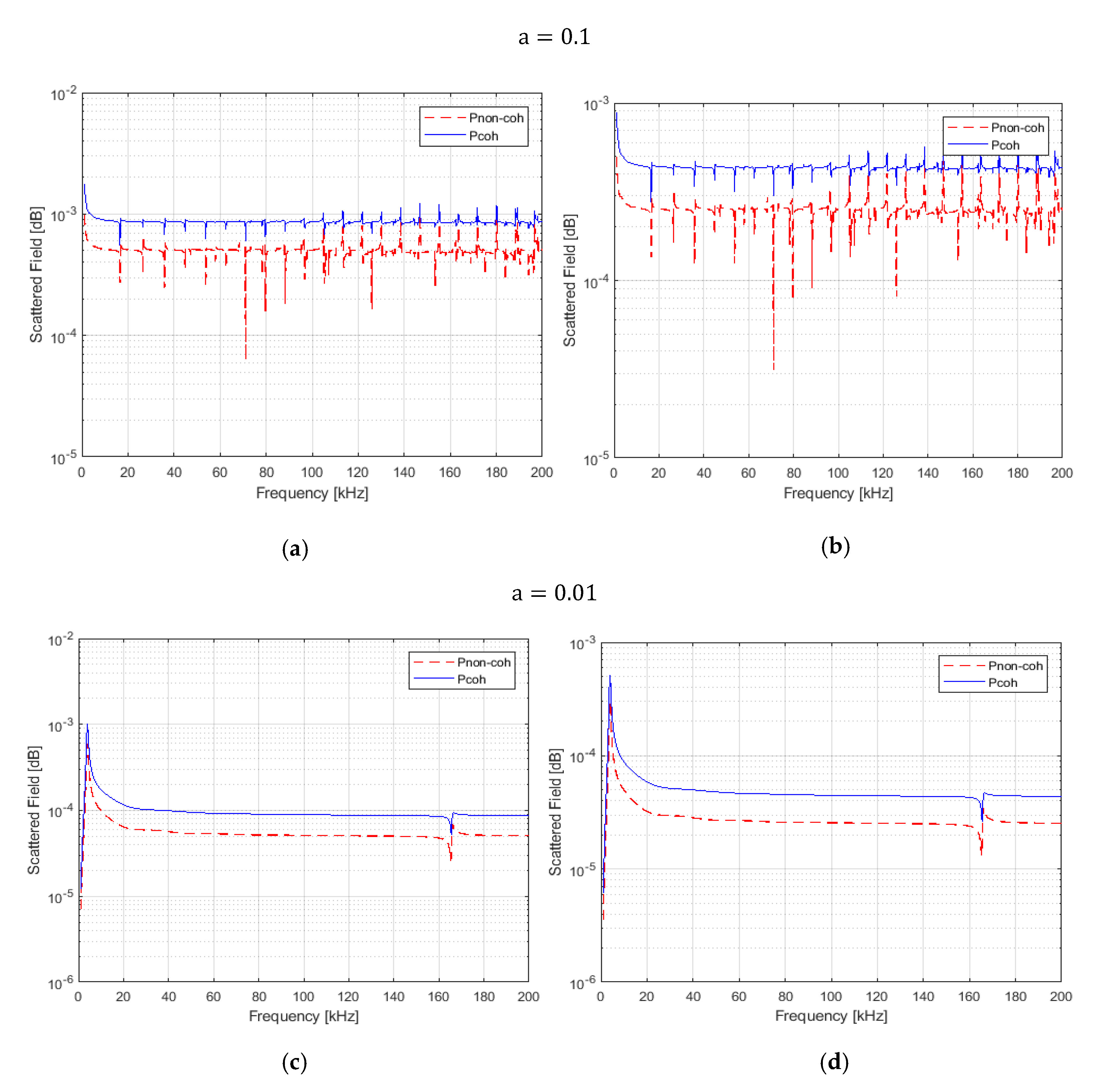
4.1. Evaluation 1: Different Gas Bubble Sizes
To evaluate the proposed method accuracy, the gas bubble acoustic scattering was compared with the real aperture method in the range . In the proposed method, first the migration range given the depth is calculated and then acoustic scattering fields of a gas bubble are calculated using the proposed scattering method and migration range in different scattering angles and stored in time series. Finally, the total scattering field of the gas bubble is obtained from the coherent combination of all stored bubble scattering fields. In the real aperture method, a gas bubble acoustic scattering is incoherently calculated at the broadside range using the proposed acoustic scattering method.
Figure 7 shows the acoustic scattering field of a gas bubble with radius a = 0.1. 0.01 cm at depths of 100 and 200 m as a function of the frequency using the proposed and comparative method.
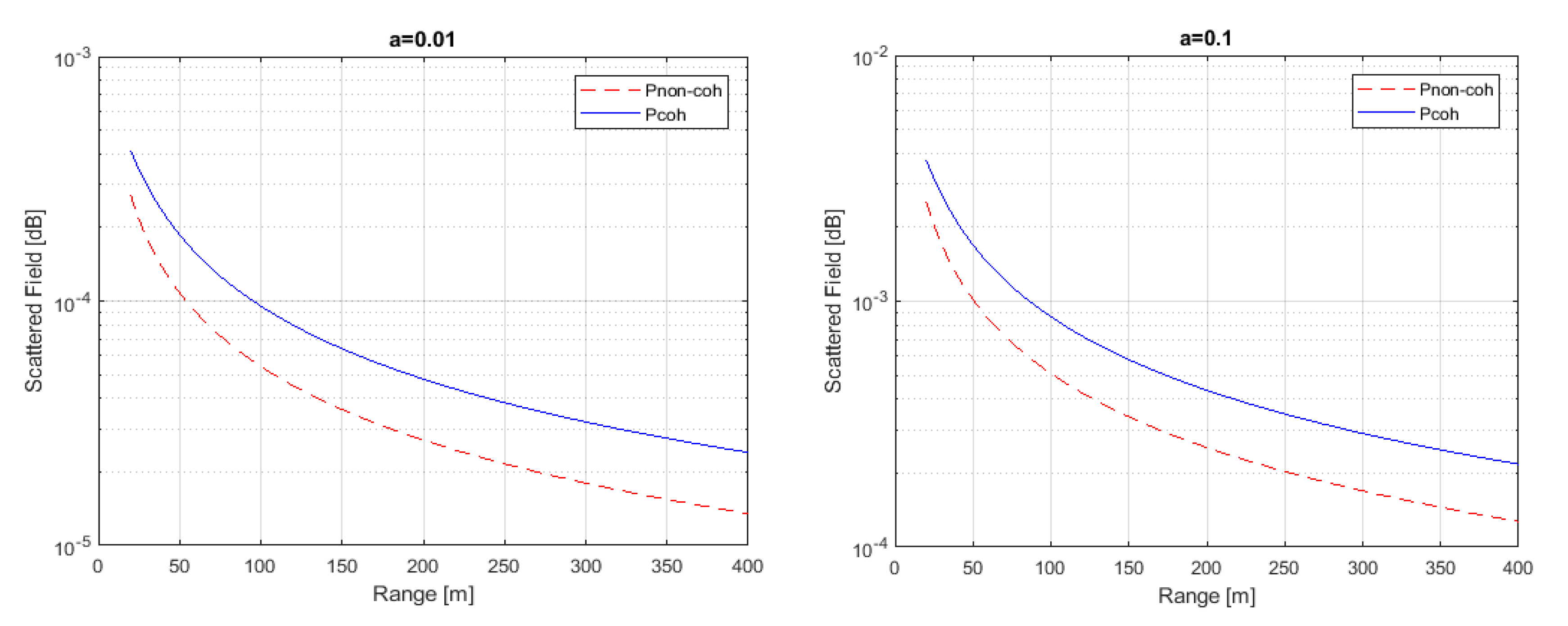
4.2. Evaluation 2: Different Depths
In another experiment, gas bubble acoustic scattering was compared using the proposed method and the real aperture method at different depths. For this purpose, migration range maps are calculated at each depth and then acoustic scattering is coherently calculated using the proposed method. For the real aperture method, gas bubble acoustic scattering is calculated in the broadside range given different depths. Some results are shown in
Figure 8.
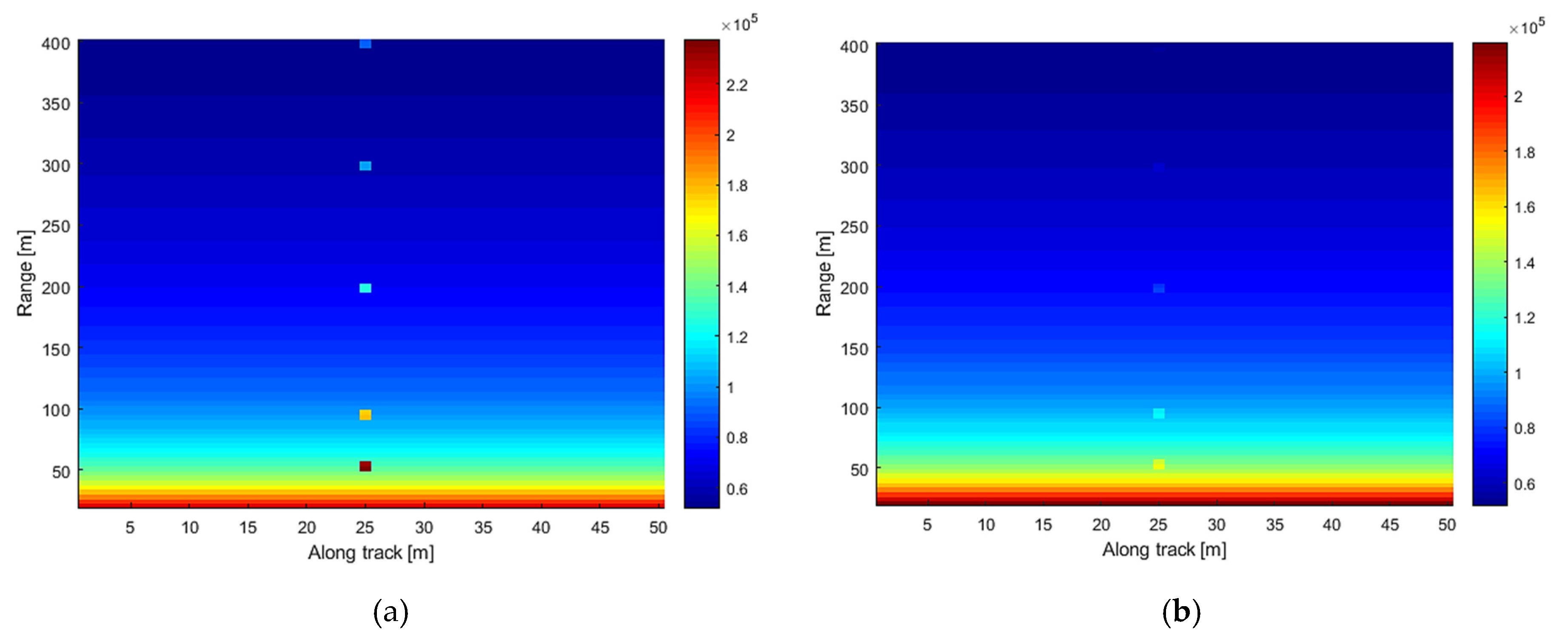
4.3. Evaluation 3: Presence of Background Scattering
In the next experiment, gas bubble acoustic scattering in the presence of a pipeline as a background echo is shown as a function of depth (range) and along-track path with the proposed method and the non-coherent real aperture method, which the target scene includes a part of the pipeline and a leak gas bubble in the along-track midway. Pipeline scattering as the background echo is calculated using the TEM acoustic scattering model from a cylinder [
14].
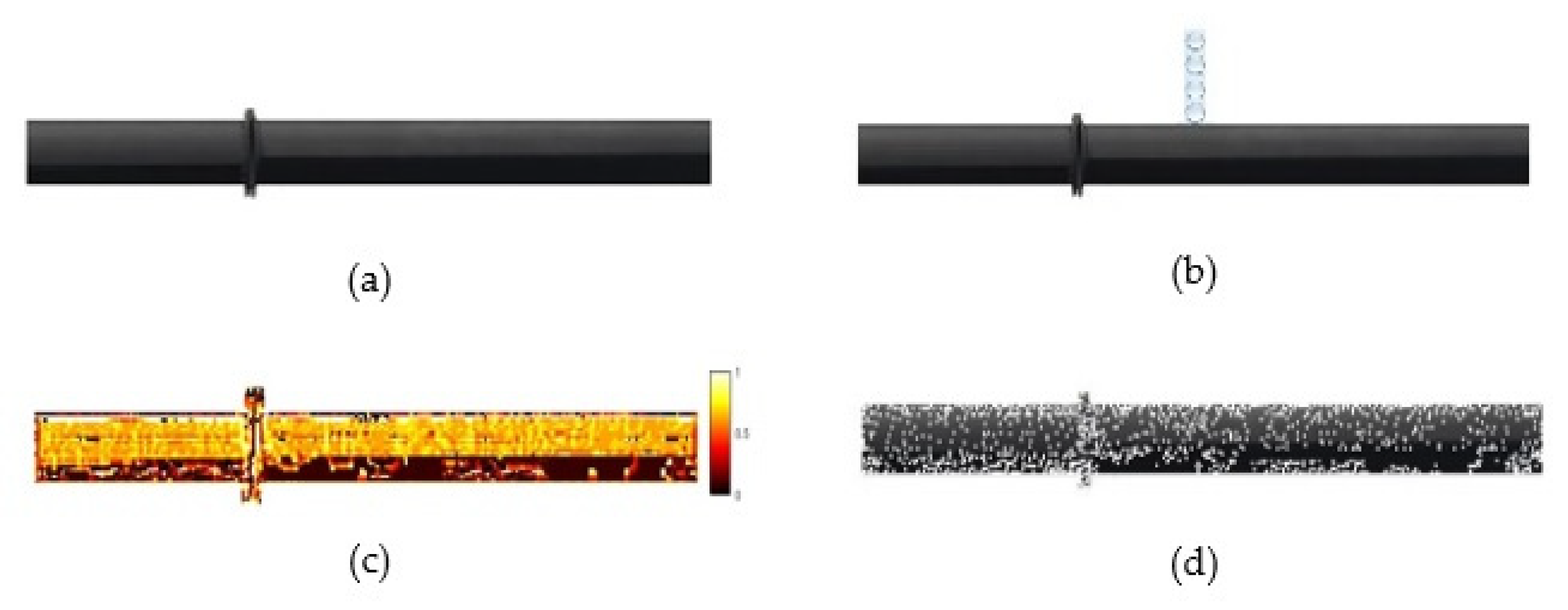
Due to the accuracy of underwater target acoustic scattering modeling depending on accurate modeling of the targets’ surface, the TEM model used an efficient non-uniform discretization method using statistical and structural information of target surface based on Local Binary Pattern (LBP) descriptors for accurate and reliable scattering modeling of underwater targets. Then the scattered pressure was computed on texture elements and arrived in a receiver by solving the Helmholtz integral equation.
Figure 9 shows a pipeline image used in the simulation and its decomposition based on the LBP descriptor.
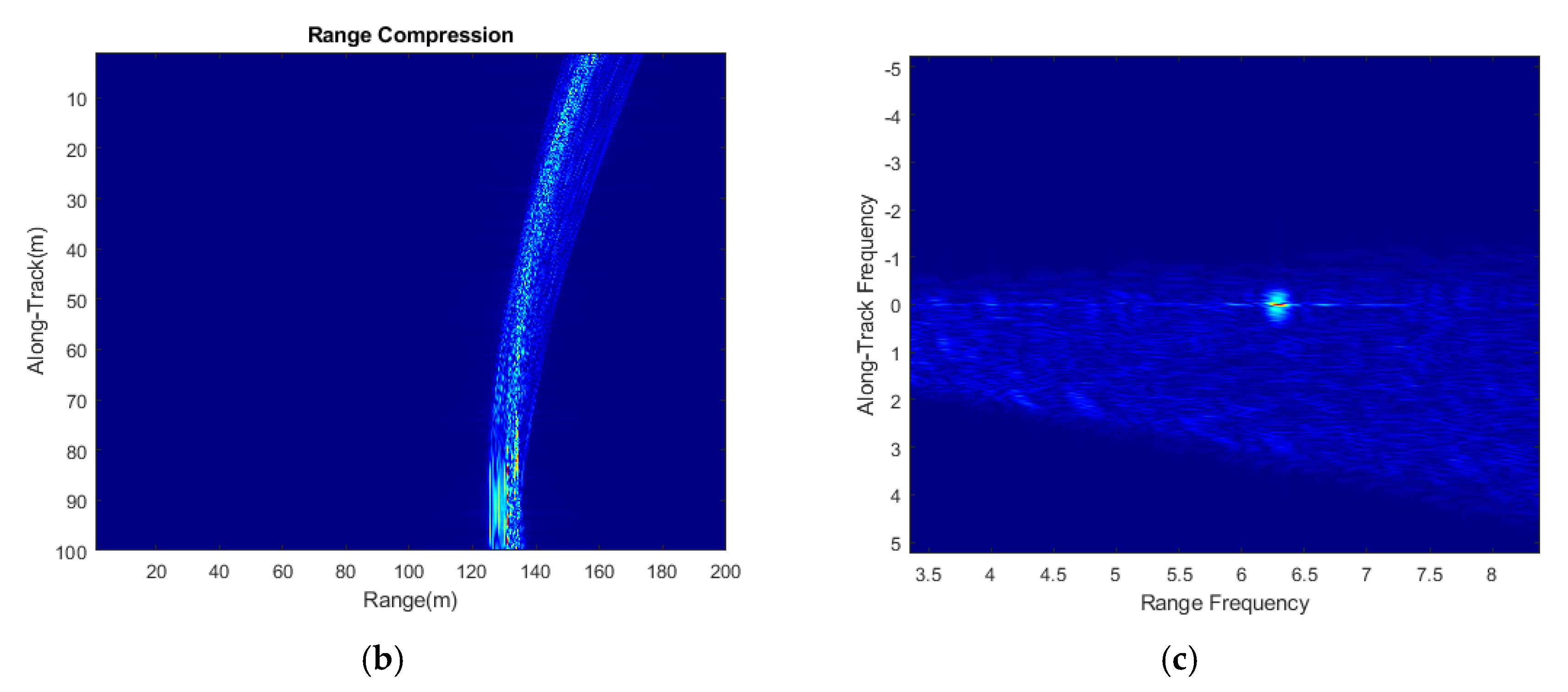
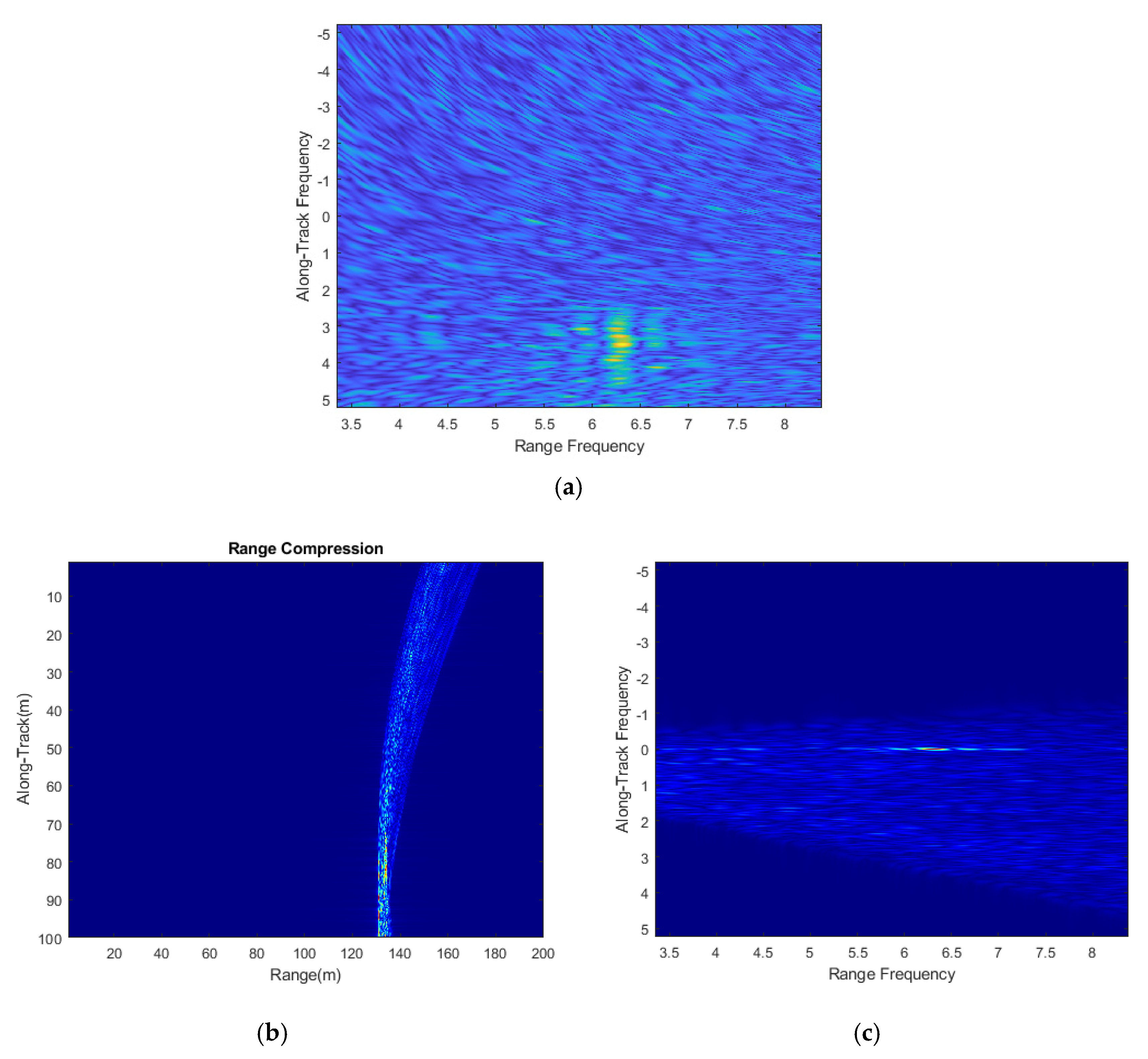
The scattering fields of points on the pipeline’s surface with a radius of one meter and a body thickness of
are collected along the synthetic aperture.
Figure 10 shows history data in the along-track and at a range of 130m, with range and along-track compression. Then data collected along the synthetic aperture of the pipeline with gas bubbles with a radius of
with range and along-track compression are illustrated in
Figure 11.
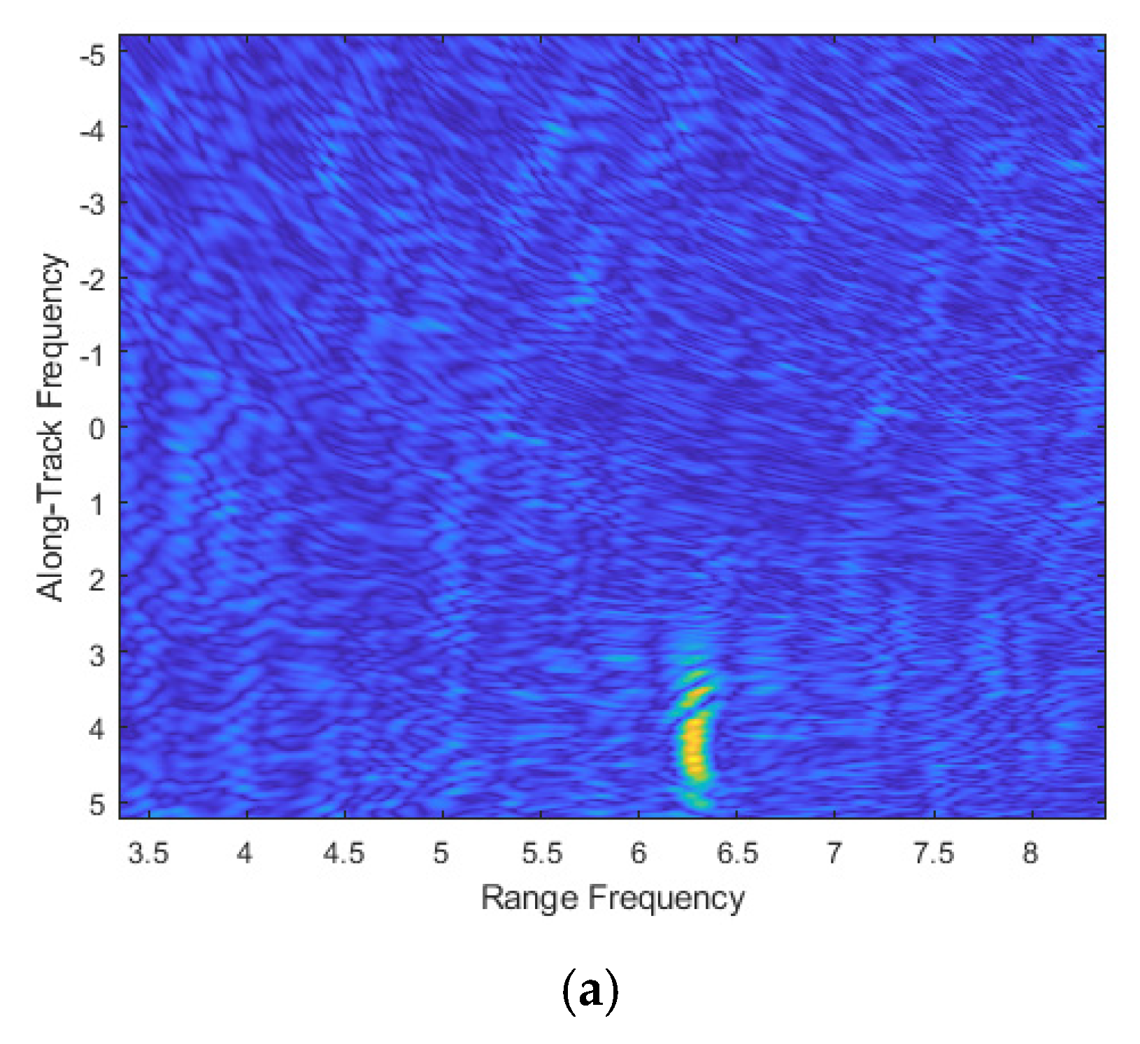
Figure 12 shows an acoustic scattering of a gas bubble with a radius of
at a frequency of
using the proposed method and the non-coherent method in the presence of an infinite cylinder scattering field with a radius of one meter and a body thickness of
at five different depths. In the proposed method, the coherent processing scattering field of the SAS system makes a high distinction of leak echo from background echoes compared to the non-coherent method, even at high depths, which is a great help to accurately detect gas leaks.
In a real aperture sonar system, the echo from each ping is individually processed and the focus is on distinguishing each echo data, while in a SAS system, the focus is on the coherent processing of the received echoes from a target during the synthetic aperture. Therefore, the SAS coherent technology is able to calculate the gas bubble acoustic scattering more accurately than the real aperture method, in which an excellent leak signal distinction of background echoes at different depths is provided. The proposed method as an efficient method in leak detection system has good potential in an automatic inspection.
5. Conclusions
Wide-ranging networks of offshore pipelines are used to transport natural gas as one of the most important energy sources in the world. The most important concern in seabed gas pipelines is the possibility of leaks due to various reasons, such as corrosion. Any mistake for leak detection can lead to dangerous environmental and economic events. Sonar systems are one of the most efficient tools for leak detection. The sonar systems’ performance depends on the ability to detect leak gas bubble signals from background signals. In current methods, a sonar system with additional equipment, an expert operator, or a combination of other sensors is used, which makes inspection a time-consuming, complicated, and costly operation.
In this paper, an efficient method based on coherent combination gas bubble acoustic scattering fields using the SAS system to detect seabed pipeline natural gas was proposed. Using the SAS system as a powerful tool for collecting accurate information at a wide area coverage and independent of the range and frequency for pipeline inspection and leak detection is the innovation of the proposed method. Moreover, an accurate acoustic scattering calculation method based on a spherical-functions model was proposed in which gas bubble scattering fields at different scattering angles were calculated and coherently combined at the range migration of the synthetic apertures. The proposed method based on reliable gas bubble modeling using the SAS system can be used effectively to improve leak detection and automatic inspection systems. The comparison results showed the accuracy of the proposed method in distinguishing gas leak signals at different depths compared to the non-coherent real aperture methods.


