Author Contributions
Conceptualization, Y.L. and S.L.; methodology, Y.L. and S.L.; software, Z.G., C.W. and C.L.; validation, Y.L. and S.L.; formal analysis, Z.G., W.S. and C.L.; investigation, Z.G., W.S. and C.L.; re-sources, S.L., Y.L.; data curation, Z.G.; Writing—original draft preparation, Y.L. and Z.G.; writing—review and editing, S.L.; visualization, Z.G.; supervision, S.L. and Y.L.; project administration, S.L. and Y.L. All authors have read and agreed to the published version of the manuscript.
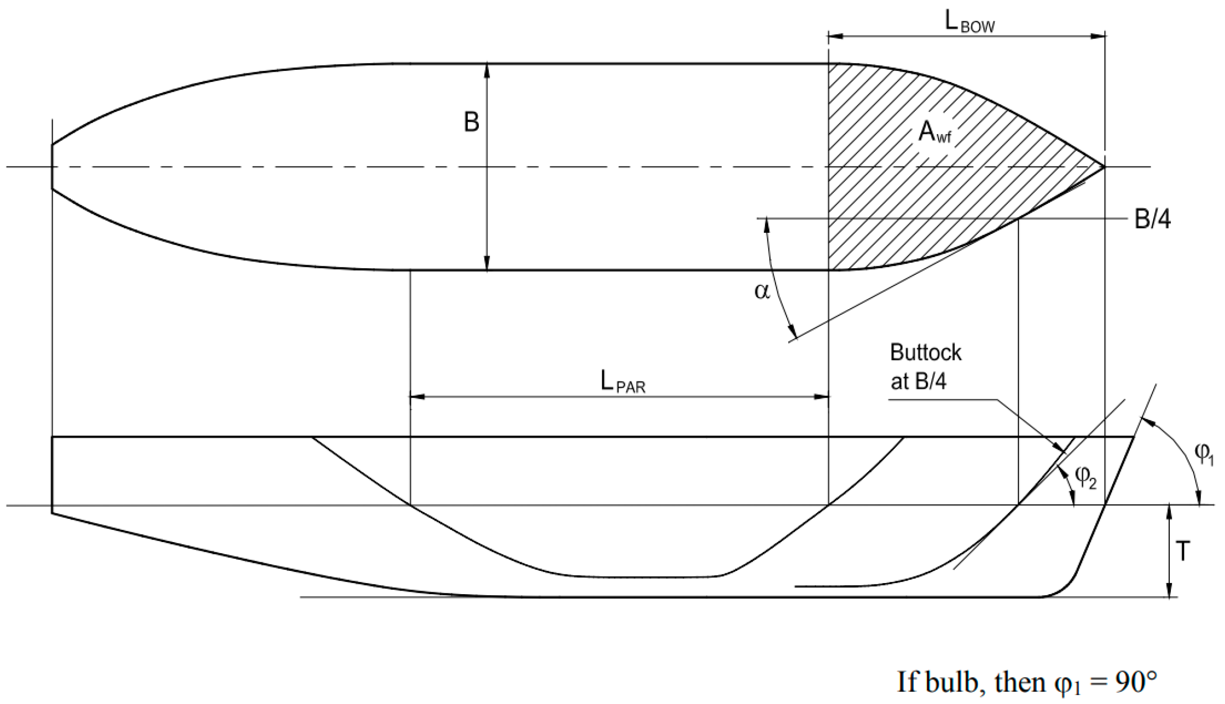
Figure 1.
Characteristic parameter value.
Figure 1.
Characteristic parameter value.
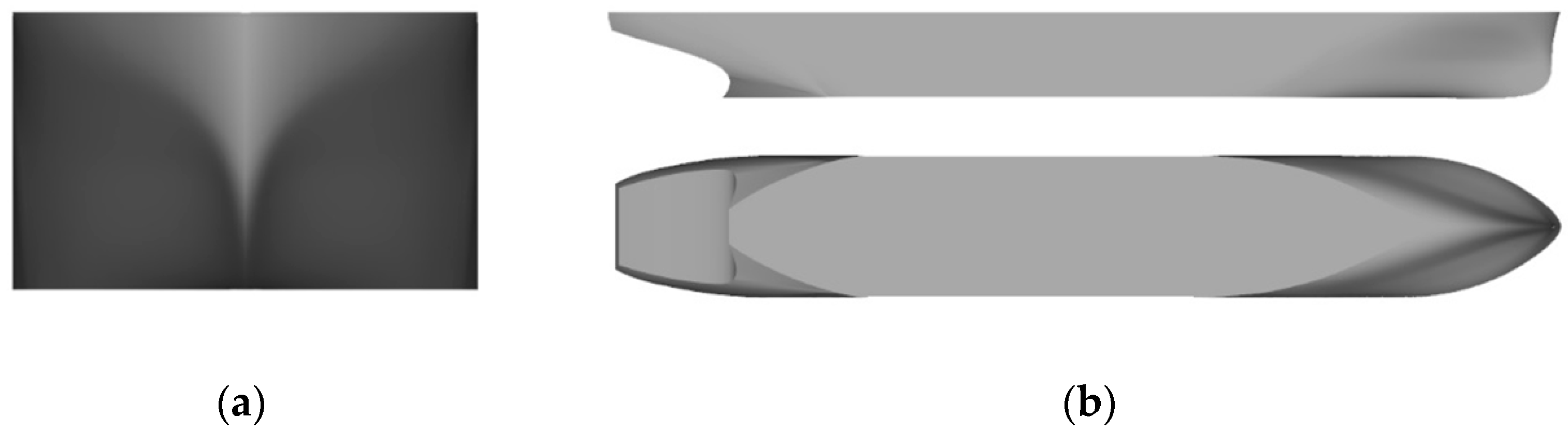
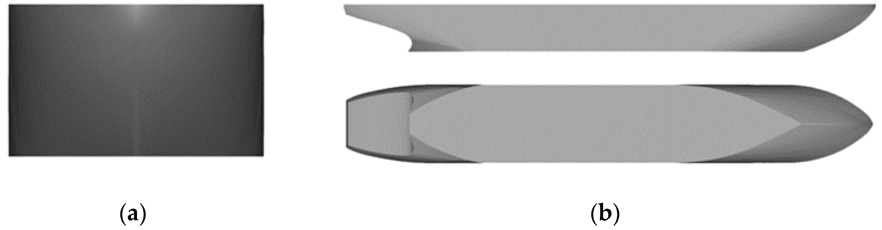
Figure 2.
Ship model of traditional icebreaker bow. (a) Front view, (b) Top view and side view.
Figure 2.
Ship model of traditional icebreaker bow. (a) Front view, (b) Top view and side view.
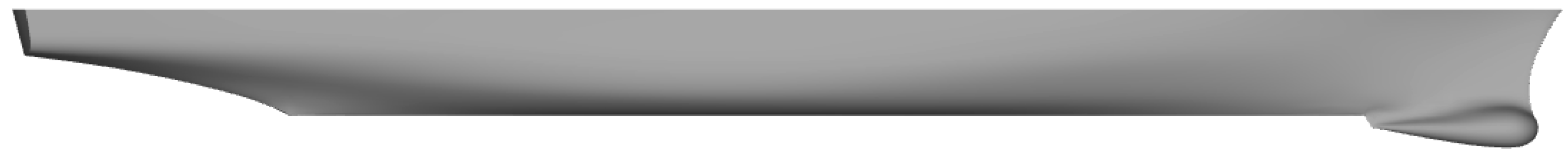
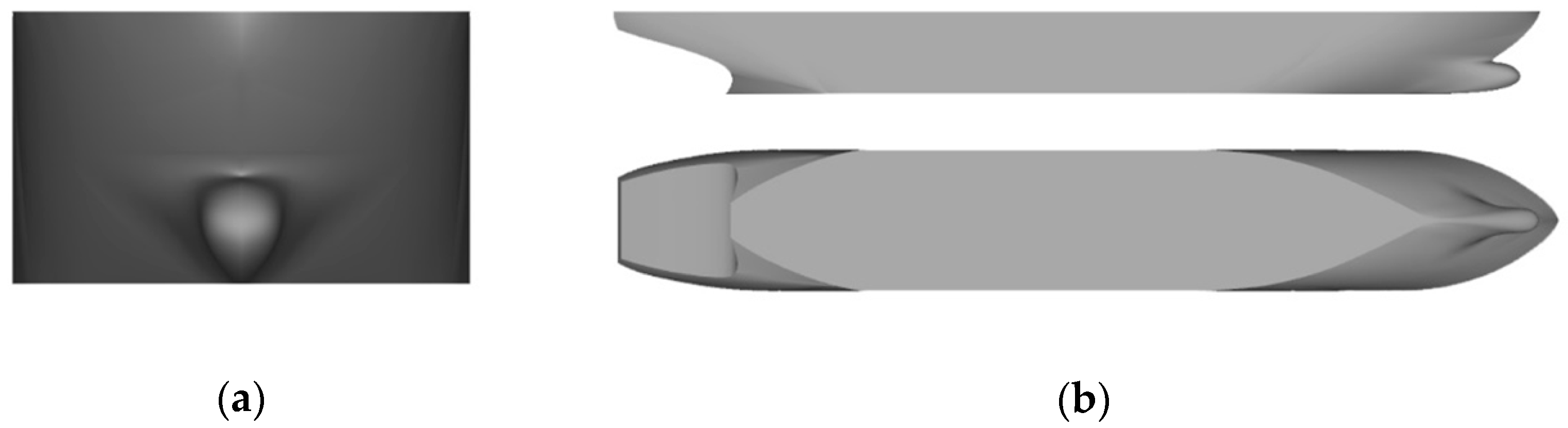
Figure 3.
Ship model of semi bow. (a) Front view, (b) Top view and side view.
Figure 3.
Ship model of semi bow. (a) Front view, (b) Top view and side view.
Figure 4.
Ship model of EEDI type of bow form. (a) Front view, (b) Top view and side view.
Figure 4.
Ship model of EEDI type of bow form. (a) Front view, (b) Top view and side view.
Figure 5.
DTMB5415 ship hull form.
Figure 5.
DTMB5415 ship hull form.
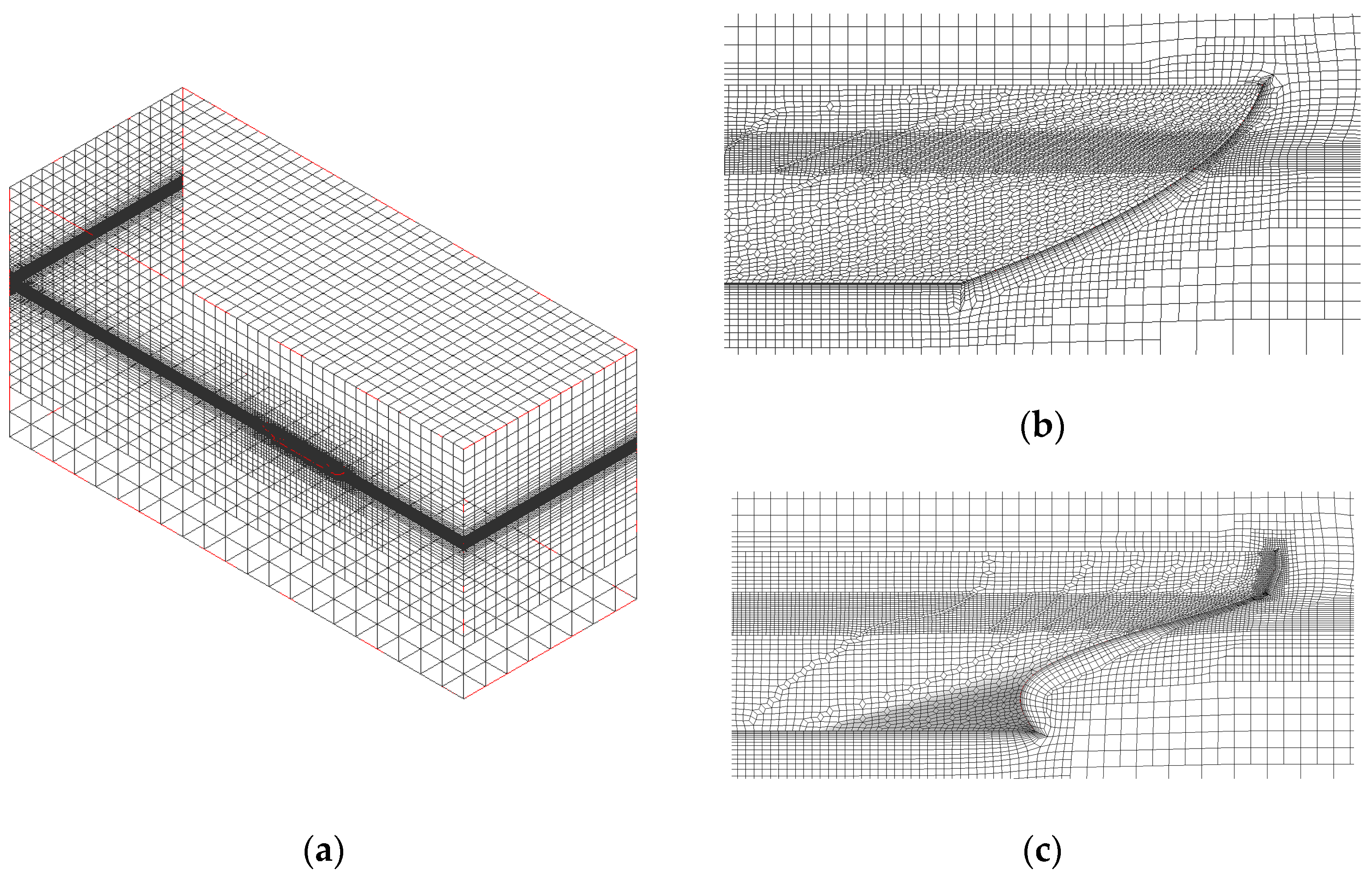
Figure 6.
Ship hull mesh. (a) Grid of all areas, (b) Bow grid, (c) Stern grid.
Figure 6.
Ship hull mesh. (a) Grid of all areas, (b) Bow grid, (c) Stern grid.
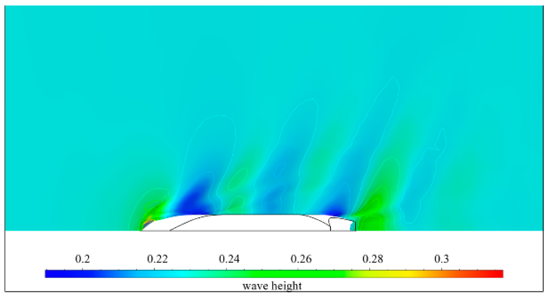
Figure 7.
Water surface wave height.
Figure 7.
Water surface wave height.
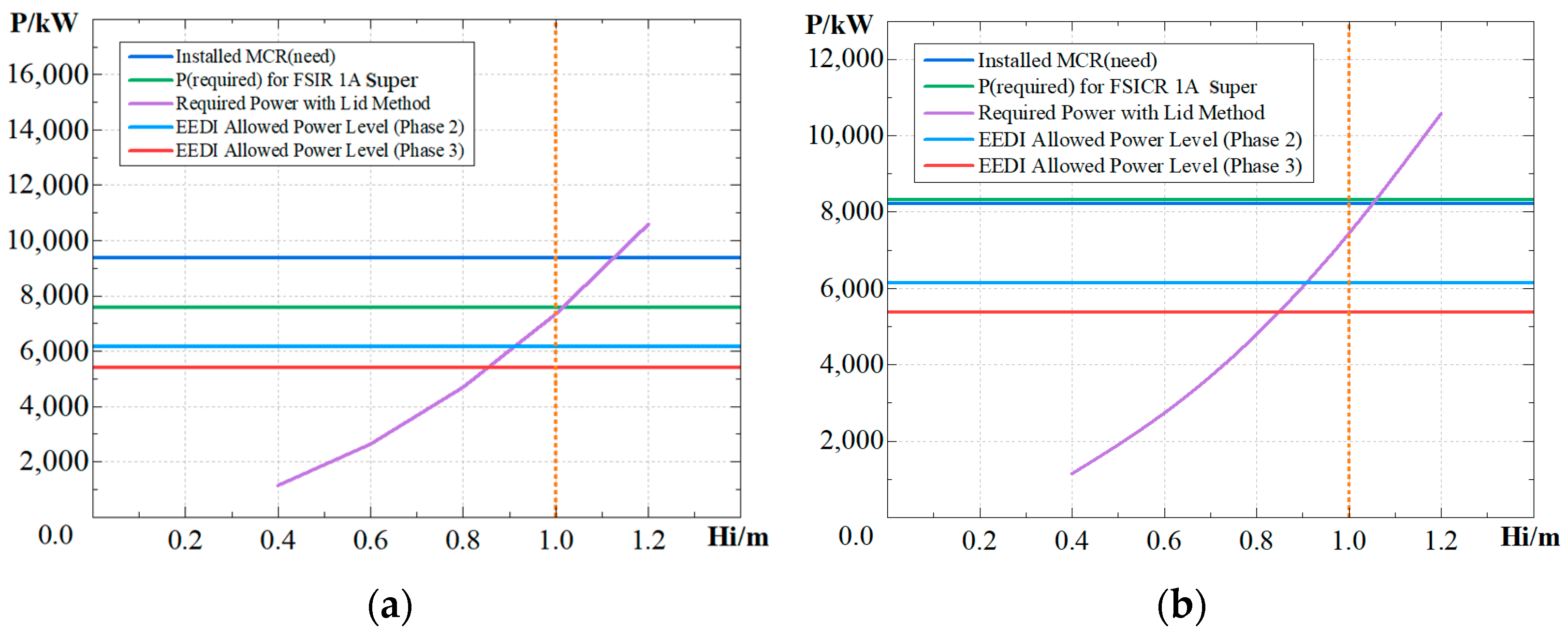
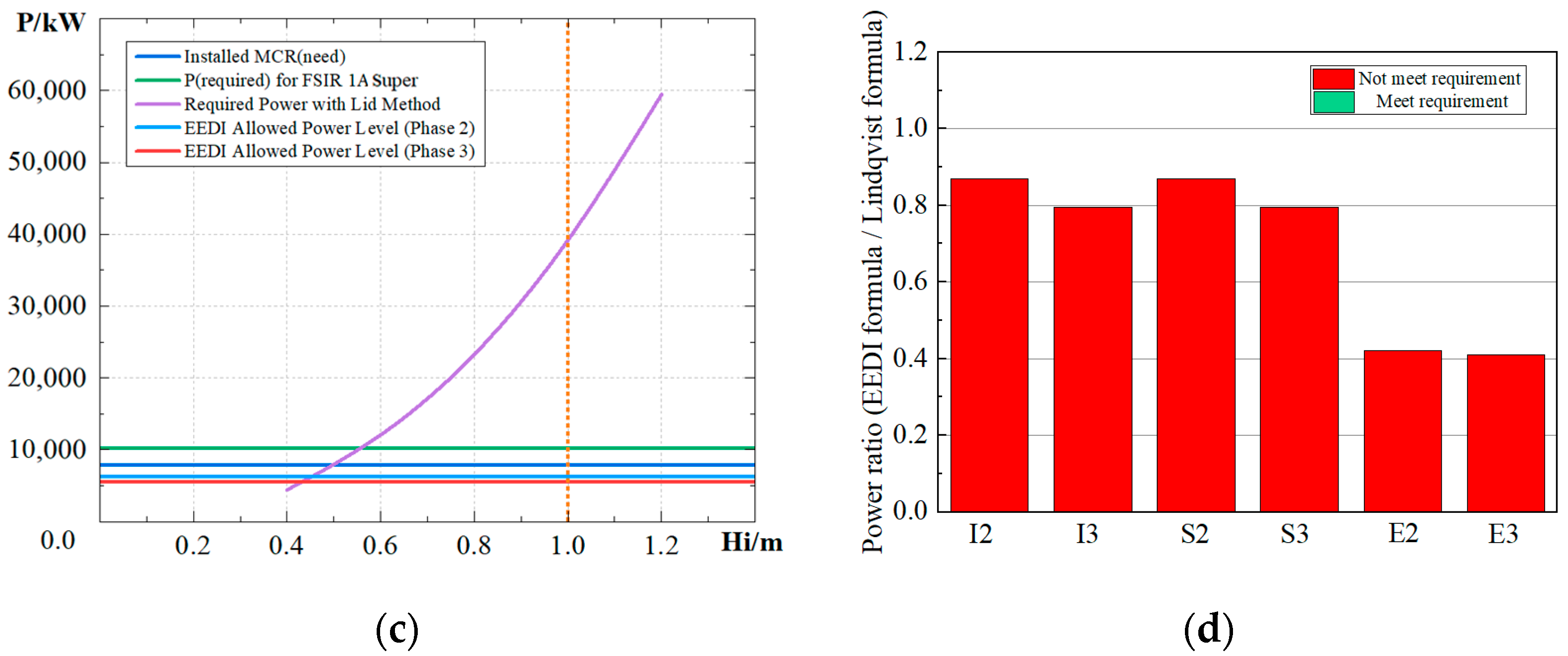
Figure 8.
Power requirement results for 1A super. (a) Power of traditional icebreaker bow, (b) Power of semi bow, (c) Power of EEDI type of bow form, (d) Power requirement comparison.
Figure 8.
Power requirement results for 1A super. (a) Power of traditional icebreaker bow, (b) Power of semi bow, (c) Power of EEDI type of bow form, (d) Power requirement comparison.
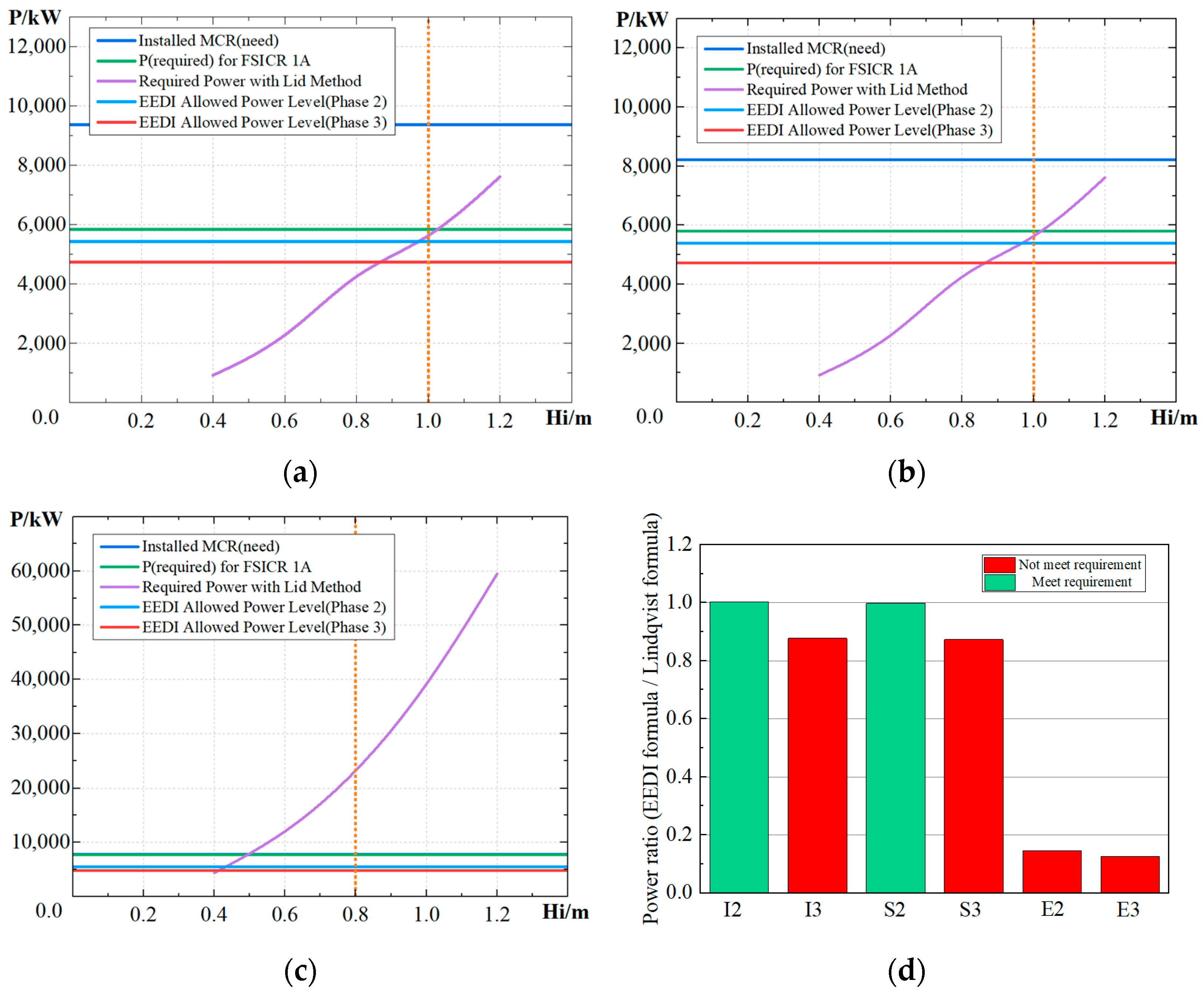
Figure 9.
Power requirement results for 1A. (a) Power of traditional icebreaker bow, (b) Power of semi bow, (c) Power of EEDI type of bow form, (d) Power requirement comparison.
Figure 9.
Power requirement results for 1A. (a) Power of traditional icebreaker bow, (b) Power of semi bow, (c) Power of EEDI type of bow form, (d) Power requirement comparison.
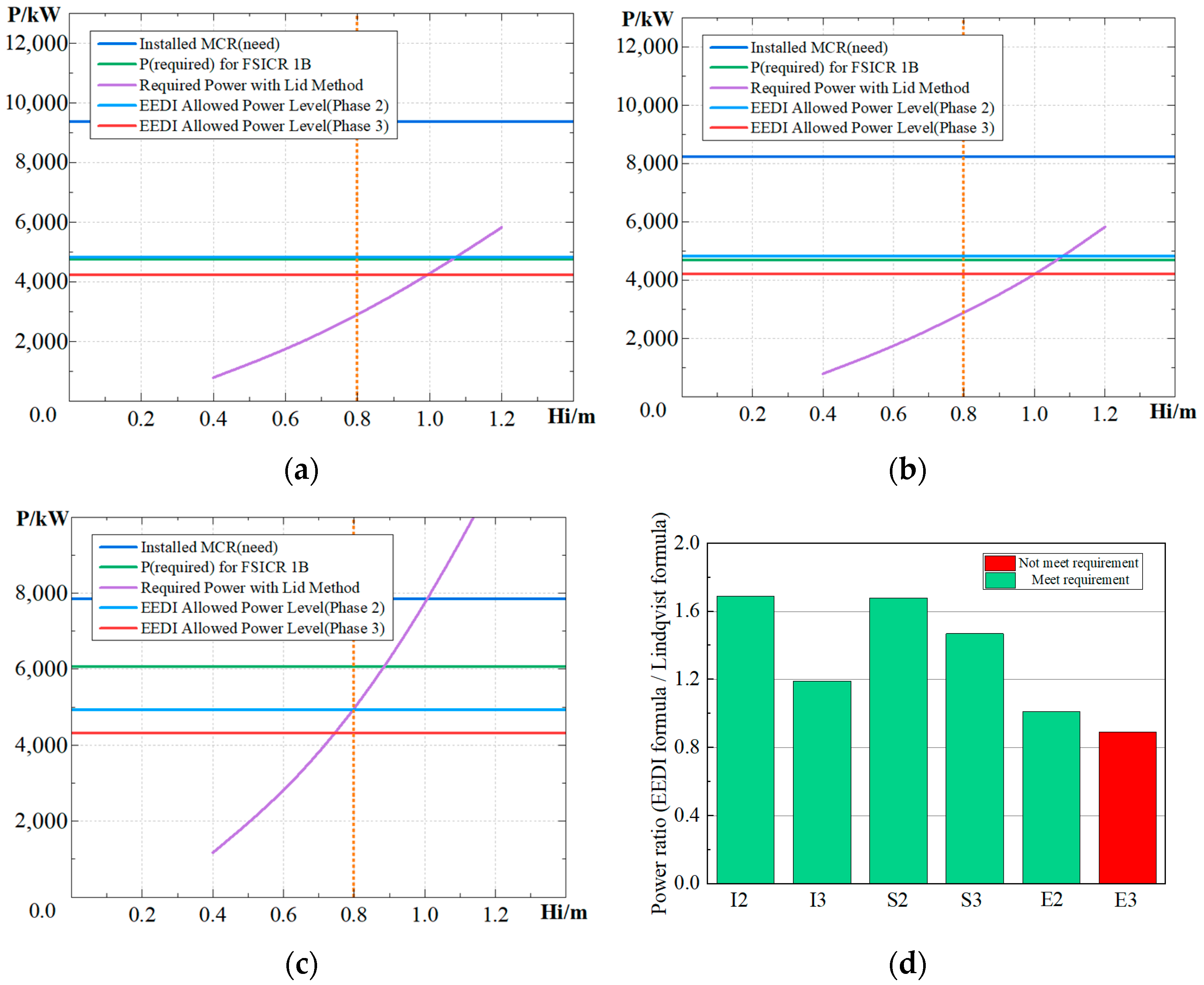
Figure 10.
Power requirement results for 1B. (a) Power of traditional icebreaker bow, (b) Power of semi bow, (c) Power of EEDI type of bow form, (d) Power requirement comparison.
Figure 10.
Power requirement results for 1B. (a) Power of traditional icebreaker bow, (b) Power of semi bow, (c) Power of EEDI type of bow form, (d) Power requirement comparison.
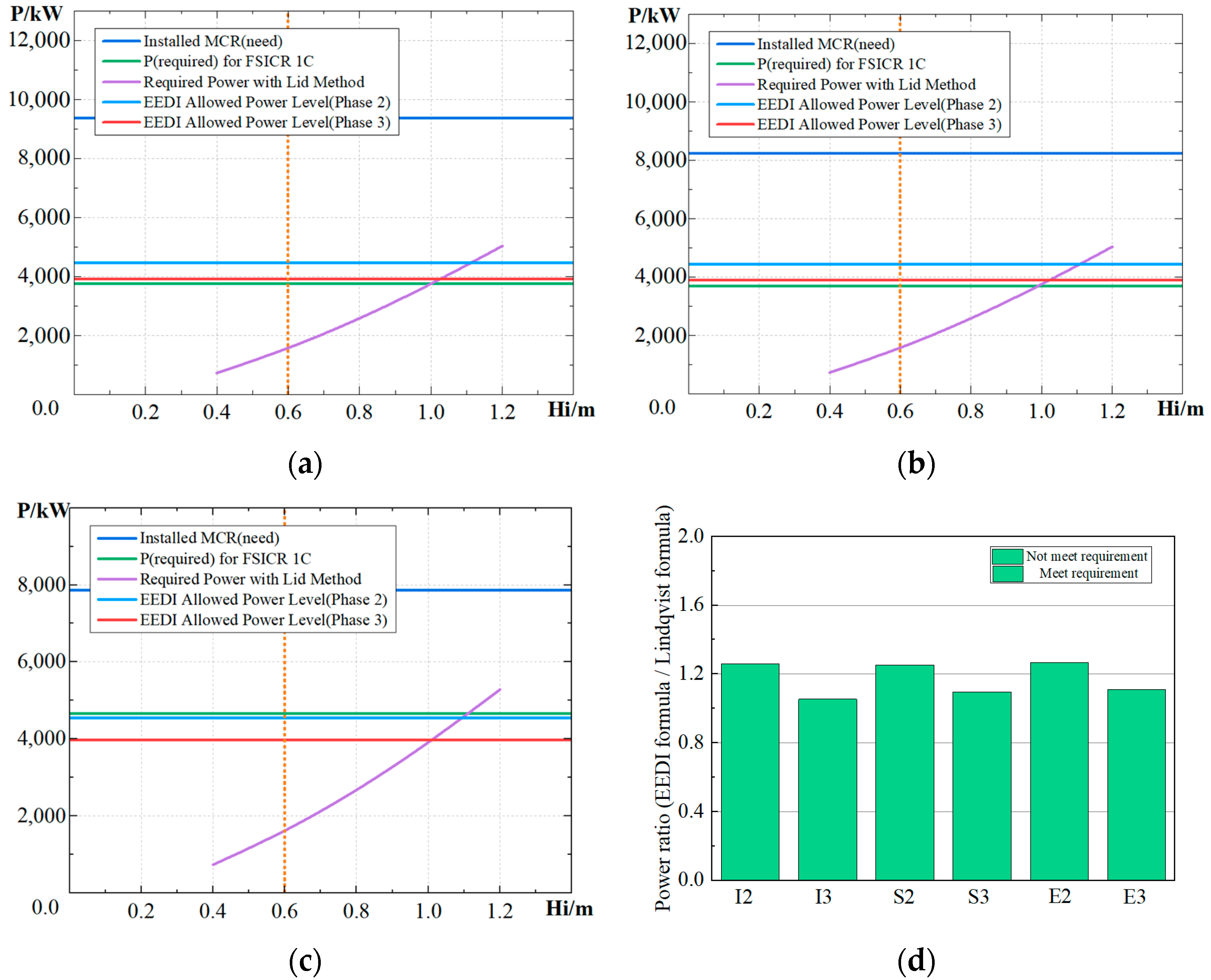
Figure 11.
Power requirement results for 1C. (a) Power of traditional icebreaker bow, (b) Power of semi bow, (c) Power of EEDI type of bow form, (d) Power requirement comparison.
Figure 11.
Power requirement results for 1C. (a) Power of traditional icebreaker bow, (b) Power of semi bow, (c) Power of EEDI type of bow form, (d) Power requirement comparison.
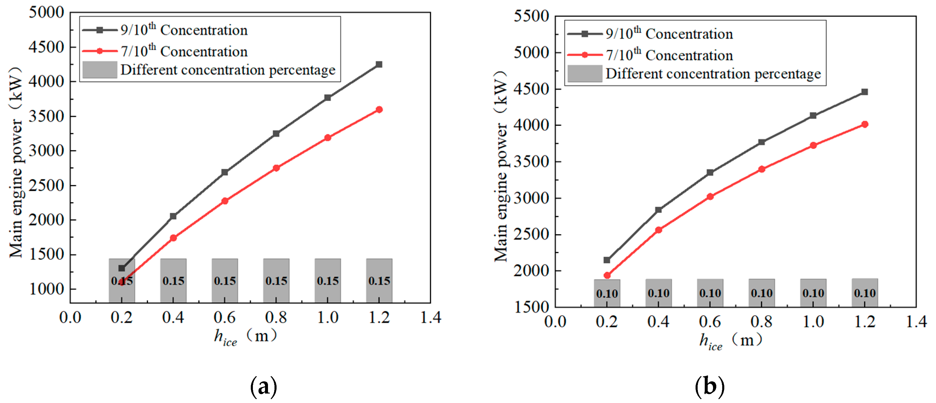
Figure 12.
Power calculation with different pack ice concentration. (a) Traditional icebreaker bow, (b) Semi bow.
Figure 12.
Power calculation with different pack ice concentration. (a) Traditional icebreaker bow, (b) Semi bow.
Table 1.
Calculation parameter value (Ke).
Table 1.
Calculation parameter value (Ke).
Propeller Hull Form or
Machinery | CP or Electric or Hydraulic
Propulsion Machinery | FP Propeller |
|---|
| One propeller | 2.03 | 2.26 |
| Two propellers | 1.44 | 1.6 |
| Three propellers | 1.18 | 1.31 |
Table 2.
Calculation parameters of different bow forms (Linqvist method and FSICR method).
Table 2.
Calculation parameters of different bow forms (Linqvist method and FSICR method).
| Name | Traditional Icebreaker Bow Specific Value | Semi Bow Specific Value | EEDI Type of Bow Form Specific Value |
|---|
| 40.15 | 90.00 | 80 |
| 33.38 | 32.41 | 48.26 |
| 28.98 | 30.92 | 46.23 |
| 0.3 | 0.3 | 0.3 |
| 900 kg/m3 | 900 kg/m3 | 900 kg/m3 |
Table 3.
Ship parameters of traditional icebreaker bow.
Table 3.
Ship parameters of traditional icebreaker bow.
| Name | Value |
|---|
| Length between perpendicular (Lpp) | 141.84 m |
| Width (B) | 22.6 m |
| Depth (D) | 13.5 m |
| Draft (T) | 9.0 m |
Table 4.
Ship parameters of semi bow.
Table 4.
Ship parameters of semi bow.
| Name | Value |
|---|
| Length between perpendicular (Lpp) | 141.84 m |
| Width (B) | 22.6 m |
| Depth (D) | 13.5 m |
| Draft (T) | 9.0 m |
Table 5.
Ship parameters of EEDI type of bow form.
Table 5.
Ship parameters of EEDI type of bow form.
| Name | Value |
|---|
| Length between perpendicular (Lpp) | 143.42 m |
| Width (B) | 22.6 m |
| Depth (D) | 13.5 m |
| Draft (T) | 9.0 m |
Table 6.
Main parameters of DTMB5415 ship model (scale ratio α = 22.832).
Table 6.
Main parameters of DTMB5415 ship model (scale ratio α = 22.832).
| Name | Value |
|---|
| Length between perpendicular (Lpp) | 5.72 m |
| Draft (T) | 0.248 m |
| Width (BWL) | 0.768 m |
| Wet area (S) | 4.824 m2 |
| Displacement (∆) | 0.551 t |
| Barycentric coordinates | (2.89 m, 0 m, 0.2475 m) |
Table 7.
Comparison of calculated resistance and experimental Value (Fr = 0.28).
Table 7.
Comparison of calculated resistance and experimental Value (Fr = 0.28).
| Grid Quantity | RT (N) | RT-EXP (N) | Error/% |
|---|
| 5 × 10⁵ | 43.41 | 45.13 | −3.81% |
| 7 × 10⁵ | 43.65 | 45.13 | −3.28% |
| 9 × 10⁵ | 44.02 | 45.13 | −2.46% |
Table 8.
Resistance value of the ship at each speed (number of grids was 7 × 10⁵).
Table 8.
Resistance value of the ship at each speed (number of grids was 7 × 10⁵).
| Fr | RT (N) | RT-EXP (N) | Error/% |
|---|
| 0.20 | 21.29 | 21.56 | −1.25% |
| 0.28 | 43.65 | 45.13 | −3.28% |
| 0.35 | 76.23 | 80.61 | −4.90% |
Table 9.
Main parameters of traditional icebreaker ship model (scale ratio α = 40).
Table 9.
Main parameters of traditional icebreaker ship model (scale ratio α = 40).
| Name | Value |
|---|
| Length between perpendicular (Lpp) | 3.546 m |
| Draft (T) | 0.225 m |
| Width (BWL) | 0.565 m |
| Wet area (S) | 3.05 m2 |
| Displacement (∆) | 0.349 t |
| Barycentric coordinates | (1.7688 m, 0 m, 0.1889 m) |
Table 10.
Numerical resistance calculation.
Table 10.
Numerical resistance calculation.
| Bow Form | | Traditional Icebreaker Bow | EEDI Type of Bow Form | Semi Bow |
|---|
Ship model
(Velocity = 1.22 m/s) | | 22.5 N | 19.5 N | 20.24 N |
Real ship
(Velocity = 7.716 m/s) | | 1,215,214 N | 1,018,334 N | 1,065,580 N |
Table 11.
Power comparison.
Table 11.
Power comparison.
| Phase2 | EEDI Allowed Power | Required Power | Installed |
|---|
| | 1A Super | 1A | 1B | 1C | 1A Super | 1A | 1B | 1C | |
|---|
| | | | | | FSICR | Lid | FSICR | Lid | FSICR | Lid | FSICR | Lid | |
|---|
| Ice bow | 6172.50 | 5425.33 | 4833.48 | 4460.77 | 7572.66 | 7344.07 | 5847.66 | 5414.04 | 4744.18 | 3563.17 | 3759.74 | 3703.58 | 9376.59 |
| Semi bow | 6145.26 | 5401.39 | 4812.15 | 4441.08 | 8330.58 | 7339.42 | 5802.20 | 5411.94 | 4687.89 | 2863.89 | 3695.41 | 3542.95 | 8222.02 |
| EEDI bow | 6289.29 | 5530.44 | 4928.77 | 4549.71 | 10,260.42 | 54,369.31 | 7690.13 | 38,285.35 | 6078.66 | 4868.00 | 4657.35 | 3591.88 | 7857.47 |
| Phase3 | EEDI Allowed Power | Required Power | Installed |
| | 1A Super | 1A | 1B | 1C | 1A Super | 1A | 1B | 1C | |
| | | | | | FSICR | Lid | FSICR | Lid | FSICR | Lid | FSICR | Lid | |
| Ice bow | 5400.93 | 4747.16 | 4229.30 | 3903.17 | 7572.66 | 7344.07 | 5847.66 | 5414.04 | 4744.18 | 3563.17 | 3759.74 | 3703.58 | 9376.59 |
| Semi bow | 5377.10 | 4726.21 | 4210.63 | 3885.95 | 8330.58 | 7339.42 | 5802.20 | 5411.94 | 4687.89 | 2863.89 | 3695.41 | 3542.95 | 8222.02 |
| EEDI bow | 5503.12 | 4839.13 | 4312.67 | 3981.00 | 10,260.42 | 54,369.31 | 7690.13 | 38,285.35 | 6078.66 | 4868.00 | 4657.35 | 3591.88 | 7857.47 |
Table 12.
DuBrovin calculation parameters selected for this ship model (traditional icebreaker bow).
Table 12.
DuBrovin calculation parameters selected for this ship model (traditional icebreaker bow).
| Parameter Hull Form | Value | Parameter Hull Form | Value |
|---|
| Ship width, B (m) | 22.6 | Length, L (m) | 150.25 |
| Distributed intensity of crushed ice, r | 0.9/0.7 | oefficient of friction,
| 0.04 |
| Ice thickness, hice/(m) | 0.2–1.2 | Half of the incident angle, /(°) | 20.075 |
| Crushed ice density, /(kg/m3) | 917 | | 0.7176 |
| Power factor, n | 1.5 | | |
Table 13.
DuBrovin calculation parameters selected for this ship model (Semi bow).
Table 13.
DuBrovin calculation parameters selected for this ship model (Semi bow).
| Parameter Hull Form | Value | Parameter Hull Form | Value |
|---|
| Ship width, B (m) | 22.6 | Length, L (m) | 150.25 |
| Distributed intensity of crushed ice, r | 0.9/0.7 | Coefficient of friction,
| 0.04 |
| Ice thickness, hice/(m) | 0.2–1.2 | Half of the incident angle, /(°) | 20.075 |
| Crushed ice density, /(kg/m3) | 917 | Precursor rhomboid coefficient,
| 0.7039 |
| Power factor, n | 1.5 | | |


