Article

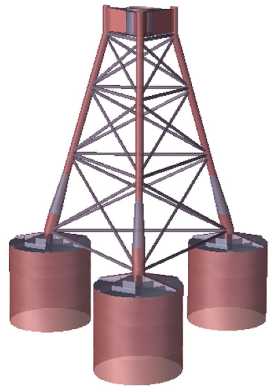
Laboratory Study of Integrated Wet-Towing of a Triple-Bucket Jacket Foundation for Far-Offshore Applications

1
School of Civil Engineering, Tianjin University, Tianjin 300072, China
2
State Key Laboratory of Hydraulic Engineering Simulation and Safety, Tianjin University, Tianjin 300072, China
3
School of Management and Economy, Tianjin University, Tianjin 300072, China
*
Author to whom correspondence should be addressed.
J. Mar. Sci. Eng. 2021, 9(11), 1152; https://doi.org/10.3390/jmse9111152
Submission received: 15 September 2021 / Revised: 11 October 2021 / Accepted: 15 October 2021 / Published: 20 October 2021
(This article belongs to the Topic Marine Renewable Energy)

Abstract

:
As a form of clean and low-carbon green energy, offshore wind power occupies an important position in the global energy structure. With the rapid development of the wind power industry, wind power projects gradually develop from offshore to far-offshore sea areas. The multi-bucket jacket foundation is a considerable foundation type for far off-shore projects, but high installation costs involving ship transportation with parted components and field installation has significantly hindered its wide application. In this study, based on a 6.7-MW triple-bucket jacket foundation (TBJF) project of a deep-sea wind farm in China, a new integrated wet-towing method of “jacket + triple-bucket foundation” composite structure was proposed, which is suitable for far long-distance transportation of far-offshore applications. The static-model test of both self-stability and wet-towing stability was conducted. Based on the test and the numerical results, the natural period of the foundation for different draft depths in hydrostatic water and the stability for different eccentric loads were first evaluated. Then, the effects of different wet-towing modes and sea conditions on the stability of the TBJF were investigated. Finally, the optimal wet-towing mode and applicable sea conditions for the TBJF structure were proposed.

1. Introduction

With the ongoing transformation of the global energy infrastructure, offshore wind-power, as a clean renewable energy has been widely used around the world [1,2]. Compared with onshore wind power, offshore wind-power has many advantages such as a smaller ecological footprint, increased stability, and better efficiency [3,4,5,6]. According to the Global Wind Energy Council (GWEC) [7] statistics (see Figure 1), the newly installed capacity in 2020 was 5206 MW, which achieves a year-on-year increase of 19%, and the global accumulated installed capacity of offshore wind power has already reached MW.
The stability of offshore wind-turbine foundations is a prerequisite for the safe operation of wind farms [8,9]. Currently, offshore wind-power foundations, which are commonly used around the world, mainly include gravity foundation, pile foundation, tri-pod foundation, jacket foundation, bucket foundation, etc. [10,11,12,13,14,15], as shown in Figure 2. Due to near-sea conditions, wind resources are limited and the increasing energy demand has promoted the development of offshore wind power in deeper water areas. [16,17]. The far-offshore sea area is particularly rich in energy resources, but with a tough environment and expensive installation costs [18]. The applications of gravity and pile foundations are not economical for far-offshore conditions [19,20]. The jacket foundation structure, however, has a large overall stiffness and is less affected by wave and current loads, making it more suitable for far-offshore areas [21,22,23]. Furthermore, the bucket foundation enables a convenient construction and yields excellent bearing capability [24,25]. By combining the above advantages of the jacket foundation and the bucket foundation, the triple-bucket jacket foundation (TBJF) becomes a very promising technology for far-offshore applications.
The TBJF consists of the upper-jacket support structure and the lower-bucket foundation structure. It has been successfully installed in offshore wind farms in Germany [26], China [27], and other countries in the world. At present, barge transportation and floating crane sinking are commonly adopted for multi-bucket jacket foundation installation [28,29,30], as shown in Figure 3. This method is highly dependent on barge and floating cranes, which are not conducible to the reduction in the construction period and the cost, and they fail to make full use of the floating stability of the suction bucket itself.
The lower parts of the multi-bucket structure are connected with each other. When it tilts induced by wave and current load, the air buoyancy in each bucket changes, meaning a result of the point of total buoyancy is shifted. At this time, there is a restoring moment involving the presence of gravity, which can maintain the integrated stability of the structure under certain sea conditions. Moreover, the upper jacket structure of the TBJF has a small water blocking area, small wave and current load suffering, and the convenient installation of a lower suction bucket structure. The floating stability and structural characteristics of TBJF make it promising to achieve long-distance integrated wet-towing. Figure 4 describes the technical process of onshore prefabrication and debugging, offshore long-distance integrated wet-towing, and in-site sinking of TBJF. This construction method makes full use of the floating stability of the inflatable structure bucket. The floating work of “jacket + suction bucket” can be completed by conventional tugboat towing, which reduces offshore operations, economizes the construction cost, and contributes to the efficient and large-scale development of far-reaching offshore wind farms.
In order to ensure the safety of towing of offshore structures, the analysis of towing stability is significant. Towing stability is affected by many aspects (towing technology, environmental conditions, ship maneuverability, etc.). The concept of stability was first proposed by Bouguer, Atwood, and Moseley, and then scholars carried out a significant amount of research on towing resistance, heading stability, and motion response analysis. Kishimoto [31] combined the experiments and numerical simulations to investigate the effects, such as the length of towing ropes, the location of towing points, and the condition of the disabled ship on the stability of the tug. Park et al. [32] studied towing characteristics, i.e., the towing and course stabilities of tug boats, by experiments. Zeng. [33] proposed a method to match the position of towed points based on the ship’s maneuverable motion equation and three-dimensional dynamic motion equation of the towed cable and established the nonlinear global towing dynamics model of the towed cable system. Charter et al. [34] studied the heading stability of the towing system in shallow water through classical towing theory and proposed parameters related to towing stability. Varyani [35] conducted numerical simulation on the towing operation of damaged ships and pointed out that load was the greatest factor affecting the stability of the towing system of damaged ships. Based on the mature towing research [36,37,38,39], the integrated long-distance wet-towing of foundation structures came into being, and it has been successfully applied in practical engineering. Due to the good stability of the semi-submersible platform, the WindFloat [40,41] floating fan can float stably on the water and be towed to the installation sea area by tugs. Spanish Elisa/Elican [42] designed a new type of self-floating gravity foundation, which realizes the integrated wet-towing of the foundation-tower-unit. The large-diameter suction bucket foundation of the Xiangshui wind farm in China has achieved the long-distance wet-towing assisted by special ships [43,44], and the integrated in-site installation of a single unit takes only 10 h [45,46].
At present, there are few engineering cases for the integral wet-towing of the TBJF composite structure, and the floating characteristics, applicable sea conditions and reasonable towing mode are still poorly understood. Therefore, in this study, a model test and a numerical simulation were conducted for the TBJF composite structure. The integrated static stability of TBJF and the influence of different wet-towing modes and sea conditions on the wet-towing stability of TBJF were investigated, in order to provide scientific support for the application of the multi-bucket jacket foundation in practical engineering.

2. Model Test Preparation

2.1. Similarity Theory
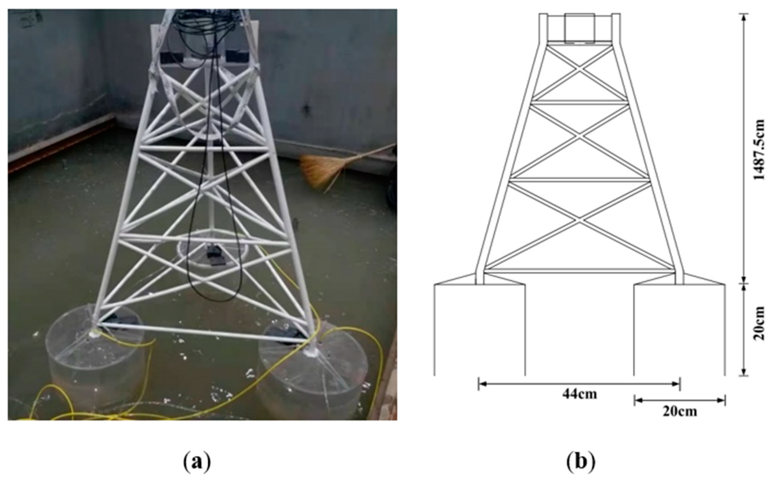
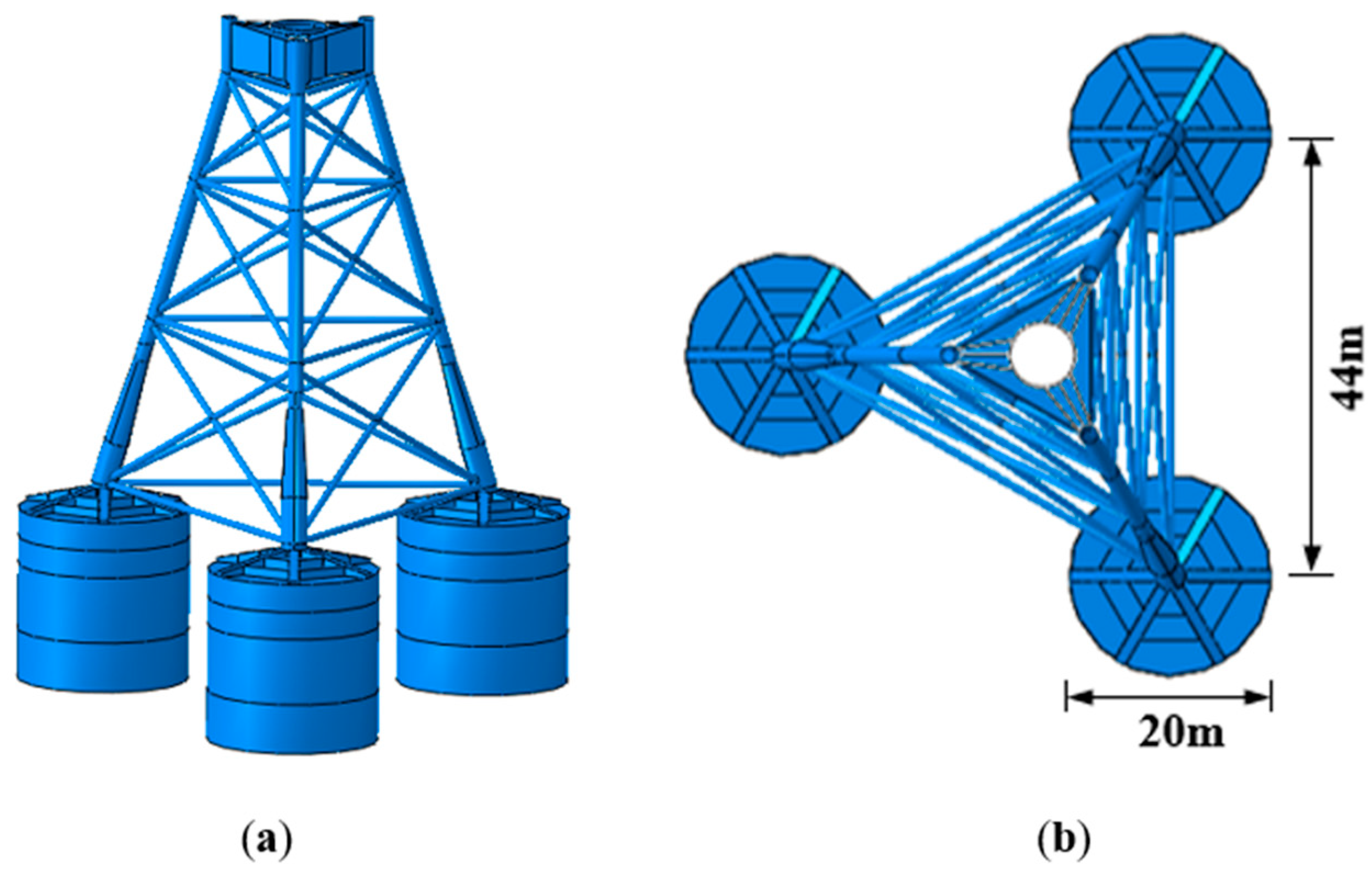
The similarity involving the Froude number and Strouhal number should be satisfied between the marine experimental model and the prototype. This can be expressed as follows:
V m g L m = V s g L s
V m T m L m = V s T s L s
where, V m , L m , T m are the velocity, wavelength, and period of the model, respectively; V s , L s , T s are the velocity, wavelength, and period of the prototype, respectively.
Considering the different environments of the model and the prototype, it was necessary to convert the water density, and the ratio was generally γ = 1.025.
Considering both flow similarity characteristics and similarity criteria, the proportion relationship between the physical quantities of the model and the prototype is shown in Table 1. The geometric similarity ratio used in this study was λ = 1 : 40 .

2.2. Model Design

This research involved a 6.7-MW wide-shallow TBJF of a deep-sea wind farm project in China, which consisted of a top-jacket structure and three identical buckets at the bottom. The top jacket was 59.5-m high, which consisted of three chord rods with a diameter of 1.8–3 m, three layers of X-type diagonal round rods with a diameter of 0.8 m, and four layers of transverse support rods with a diameter of 0.8 m. The diameter of the lower bucket was 20 m, the height was 20 m, and the distance between the center of the bucket was 44 m, as can be seen in Figure 5. Based on the geometric similarity, in model tests, the bucket height was 0.5 m, and the diameter was 0.5 m. According to the principle of gravity similarity, the weight was equal to the Froude number, and a 21.63 kg lead block was balanced according to the difference—see Figure 6. The basic model parameters are shown in Table 2.

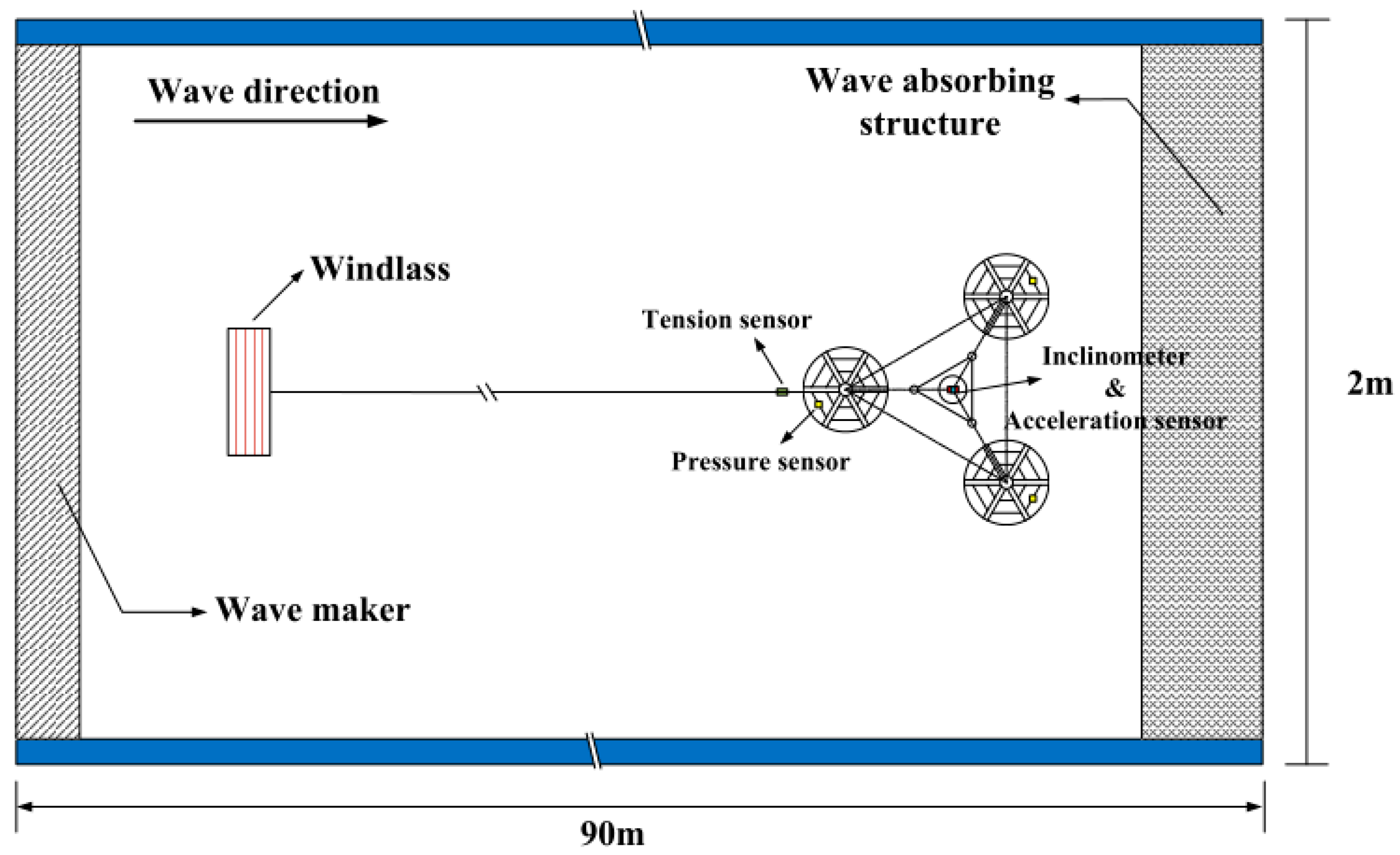
2.3. Test Arrangements

To study the static stability and wet-towing stability of the TBJF, two model tests were carried out. The specific research topics of this study were as follows:
(1)
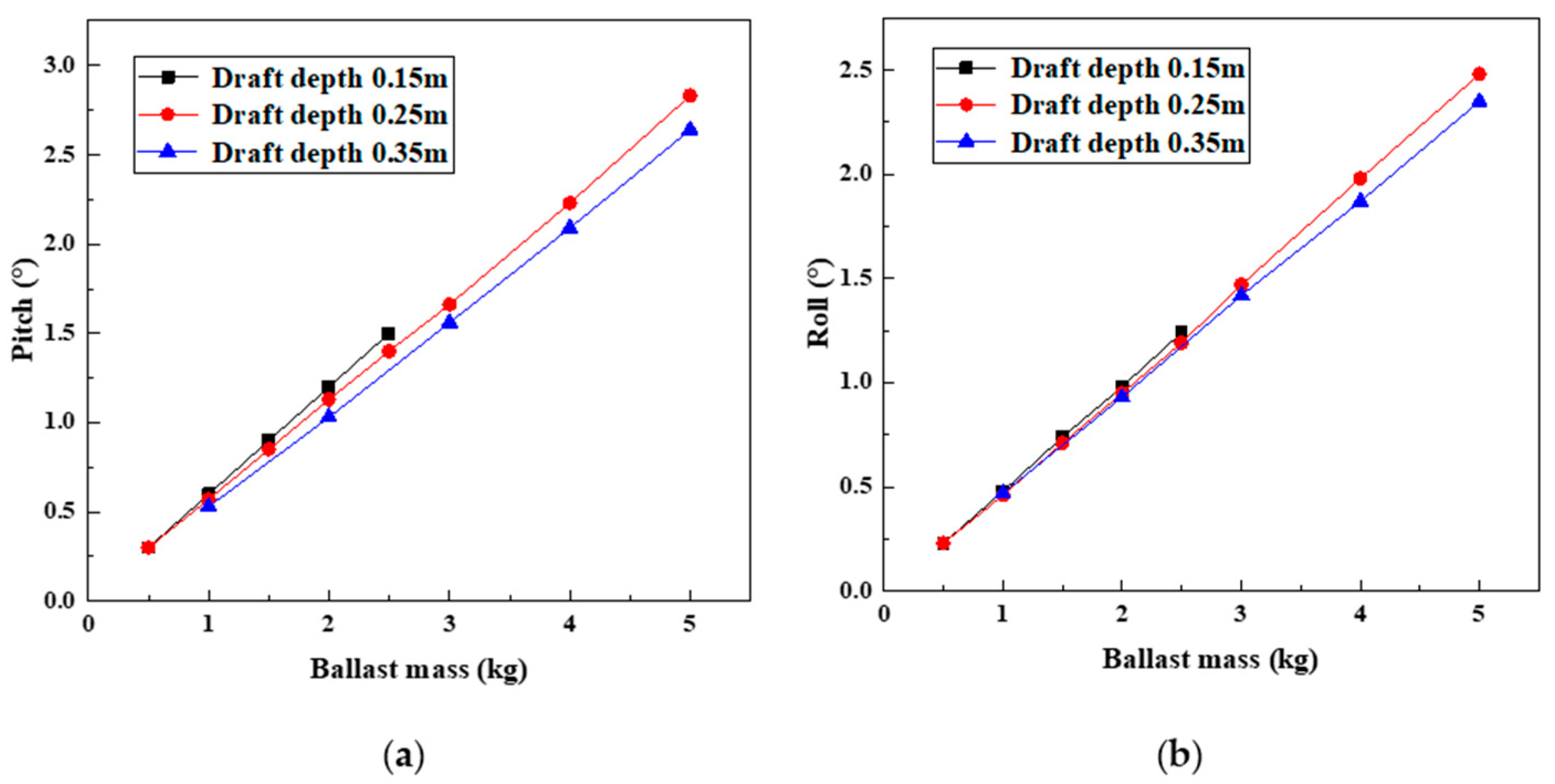
The static stability test was carried out to analyze both the natural period variation law of the TBJF under different draft depths and the pitch and roll variation law of the TBJF for different drafts and eccentric loads.
(2)
The wet-towing stability test was carried out to analyze the stability of the TBJF for different wet-towing modes and sea conditions. The effects of different draft depths, positions of towing point, wave heights, and wave periods on the wet-towing stability were evaluated.

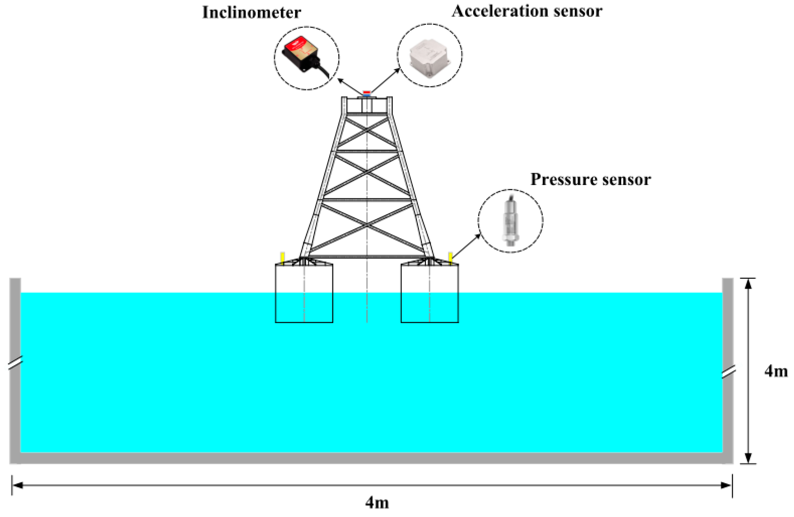
2.4. Test Equipments

The static stability test of the TBJF was carried out in a cubic sink with a 4-m inner-side length. The inclinometer and acceleration sensor were arranged at the center of the platform (on the top of the model) to monitor pitch, roll, and acceleration of the TBJF, respectively. The pressure sensor was installed at the center of each bucket top cover to monitor the pressure of each bucket. A schematic of the static stability test is shown in Figure 7.
The wet-towing stability test of the TBJF was carried out in the harbor basin, which was 90-m long, 2-m wide, and 2-m deep. It was equipped with a push-plate wave maker and a bidirectional circulating current-generator system. The wave generation period was 0.5–5 s, and the maximum wave height was 0.5 m. In the test, a constant speed winch was used to enable towing of the TBJF at a speed of 0.21 m/s. The tension sensor was connected to the wire rope of the winch to measure the towing-cable force. The schematic of the wet-towing stability test is shown in Figure 8.

3. Static Stability of the TBJF

The operating conditions for different draft depths were set to 15 cm, 25 cm, and 35 cm, as can be seen in Table 3.

3.1. Natural Period

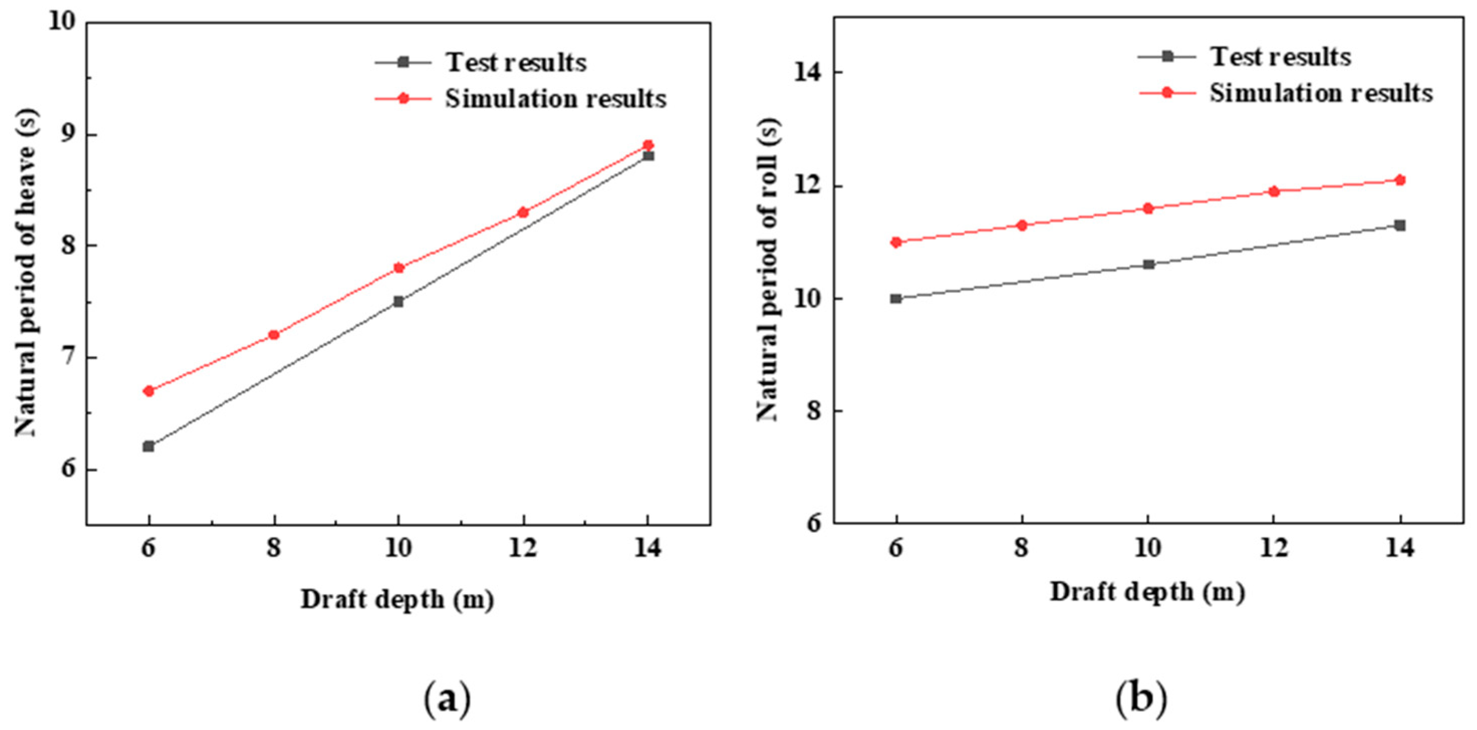
3.1.1. Natural Period of Heave

Air had been evenly pumped into the three buckets to enable the TBJF to reach an initial equilibrium state, then a vertical exciting force was applied to the TBJF, leading to the heave motion of TBJF; therefore, the natural heaving was monitored. The free attenuation curve of the heave acceleration of the TBJF in hydrostatic water versus time was recorded with the acceleration sensor. The test data were sorted and plotted, and the spectrum was obtained via Fourier transform. The results for the natural period of the heave of TBJF (for different drafts) are summarized in Figure 8 and Table 4. As shown in Figure 9, with increasing foundation draft depth, the natural period of heave increased. This was because, with increasing foundation draft depth, the volume of displaced water, induced by the walls of each bucket, increased and resulted in a decrease in buoyancy (provided by the gas in the bucket). Hence, the natural period increased gradually.

3.1.2. Natural Period of Roll

In the same way as above, a horizontal exciting was applied to the TBJF to perform a transverse free attenuation movement in hydrostatic water. The results for the natural period of roll of the TBJF for different drafts are summarized in Figure 10 and Table 5. The natural period of roll increased with increasing foundation draft depth. The reason was similar with the heave motion cases. With increasing draft depth, the buoyancy (provided by the gas in the bucket) decreased gradually, and the natural period increased gradually.

3.1.3. Numerical Simulation

The SESAM software was used to establish the prototype model of TBJF, and mutual verification between the numerical simulation and the test was carried out. The natural period, restoring arm, and towing force were compared in this study. The SESAM model of the TBJF is shown in Figure 11.
The prototype of the TBJF was established by finite element software, and the change in draft depth was achieved by adjusting the water–air ratio in the bucket. The motion amplitudes of heave and roll at different drafts were calculated. The period corresponding to the maximum motion response amplitudes of heave and roll was the natural period.
The test results (prototype scale) were compared with the numerical simulation, as shown in Figure 12. The maximum difference between the simulation and the test results was within 10%.

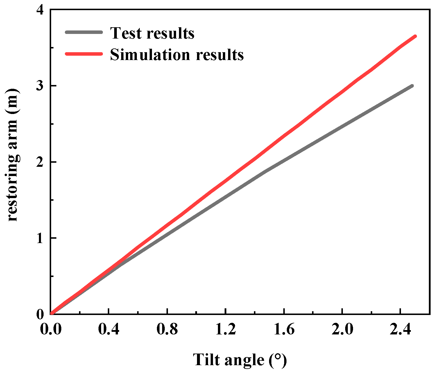
3.2. Static Stability of the TBJF

It was necessary to study the effect of an eccentric load on the stability of the TBJF because an eccentric load can produce a certain inclination angle for the TBJF. After the foundation had been inflated and levelled, the ballast blocks were superimposed from the top cover to the center of the top cover at a fixed distance. The position of the ballast blocks remained unchanged. With an increasing number of ballast blocks, the eccentric load increased gradually, and the structure tilted. The variation in inclination angle versus total mass of the ballast blocks is shown in Figure 13.
When the draft depth of the TBJF was 15 cm, the total masses of the ballast blocks were 0.5 kg, 1 kg, 1.5 kg, 2 kg, and 2.5 kg in the test. When the draft depth of TBJF was 25 cm and 35 cm, to ensure that the measured values for pitch and roll changed significantly, the total masses of the ballast blocks were 1 kg, 2 kg, 3 kg, 4 kg, and 5 kg in the test. It can be seen from Figure 13 that an increasing total ballast block mass can gradually increase the pitch and roll generated by the TBJF. Furthermore, with increasing draft depth, the pitch and roll, which was generated, decreased. This was because the increasing structural draft could provide a larger restoration force arm for the foundation when tilting, which decreased the tilting angle.
In the hydroD module, the initial stability of the TBJF in the self-floating state was studied.
The tilt angle of the model under the 10-m draft was converted into the restoring arm and compared with numerical simulation. As shown in Figure 14, the test results (prototype scale) were close to the numerical simulation results when the tilt angles were relatively small. Although for greater tilt angles the difference between the test results and the simulation showed a remarkable increase, the maximum difference was still within 20%.

4. Wet-Towing Stability of the TBJF

4.1. Effect of the Wet-Towing Mode on the TBJF Stability

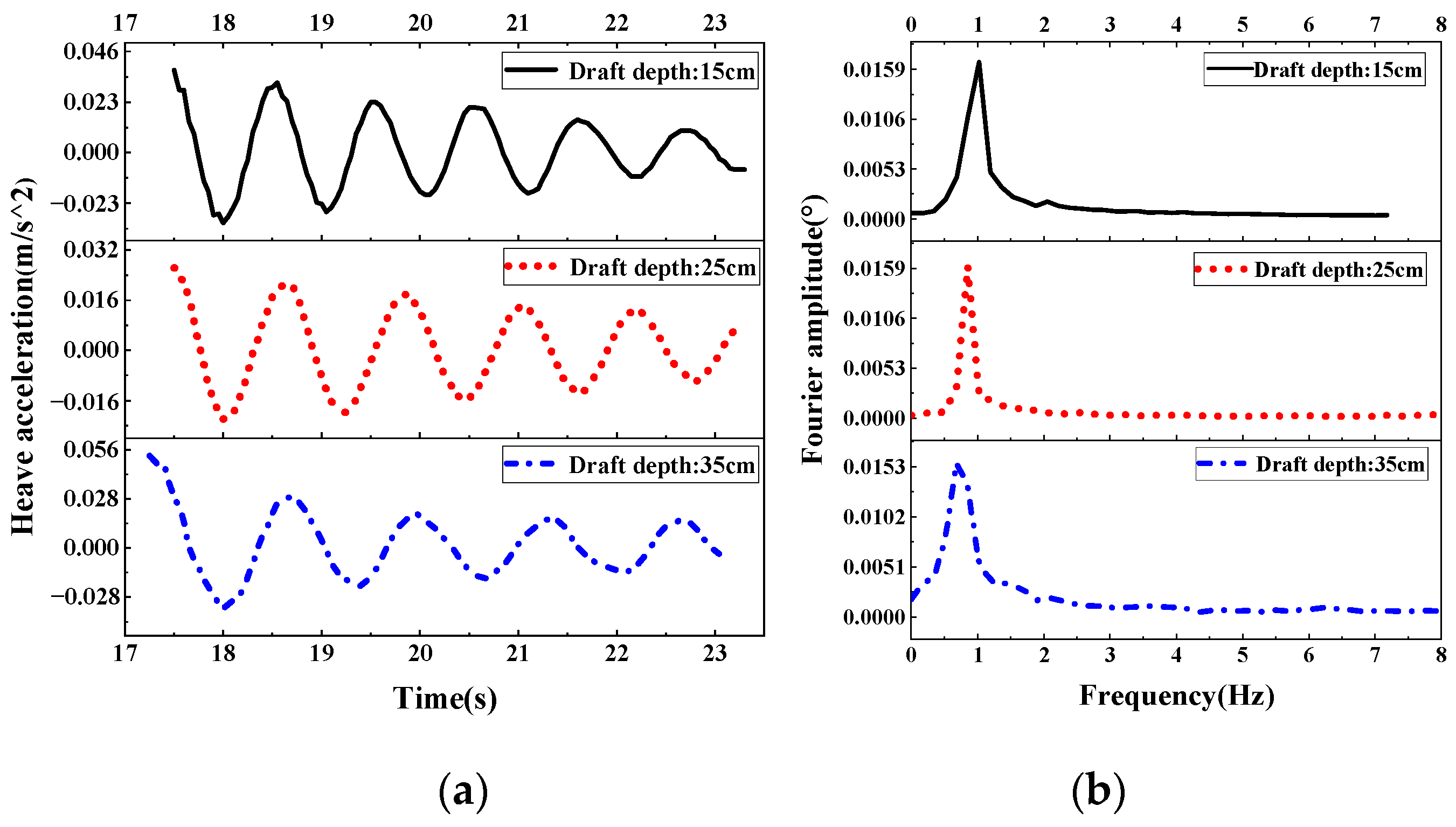
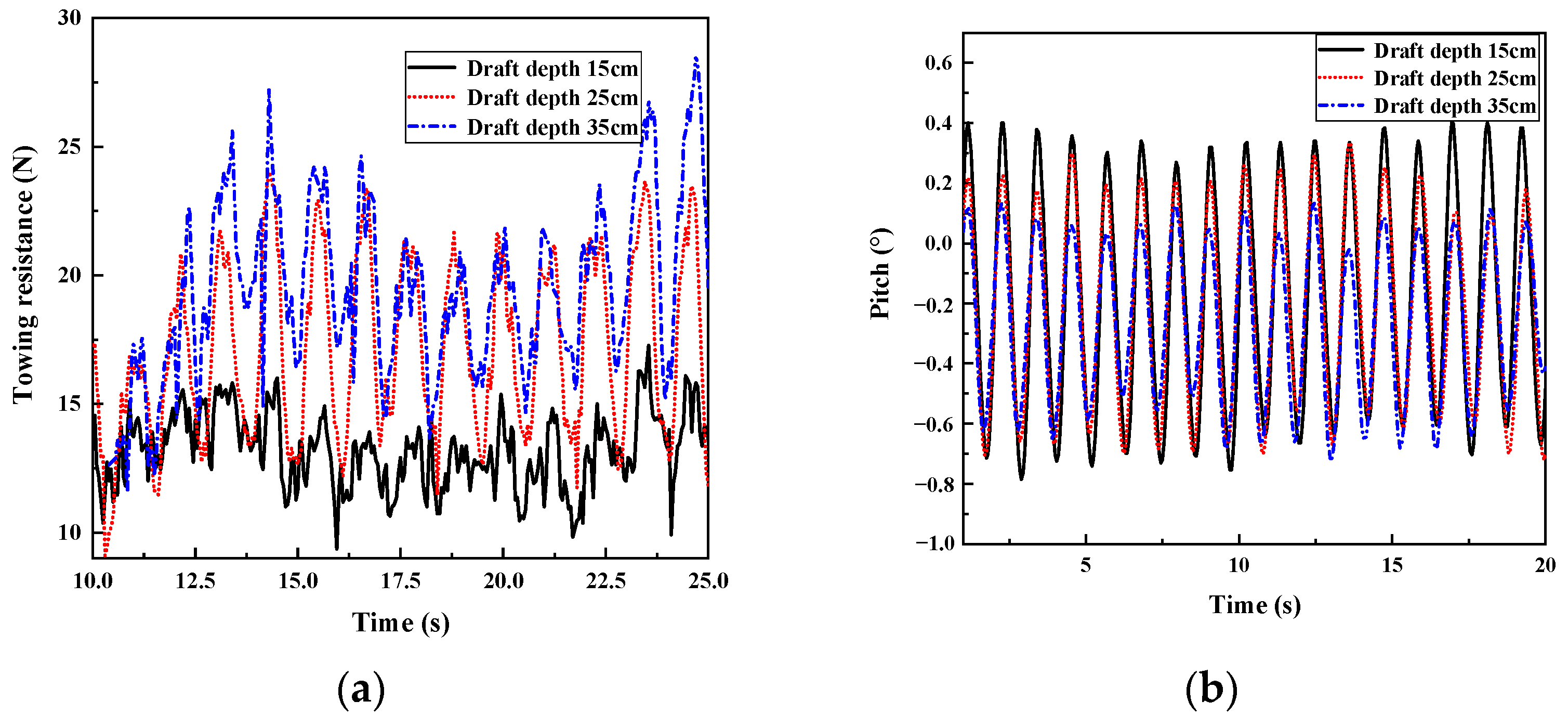
4.1.1. Effect of Draft Depth

The towing speed of the model was set to 0.41 knots, and the towing position was situated 0.05 m above the water surface. The structure initially reached the level state by adjusting the air pressure for each bucket. The draft depths were 0.15 m, 0.25 m, and 0.35 m, respectively, for towing for regular waves (with a wave height of 2.5 cm and a period of 1.34 s). The towing conditions are shown in Table 6. The dynamic response of the TBJF for different draft depths is shown in Figure 15.
As can be seen in Figure 15a, the towing force showed a fluctuated variation with the towing process and a higher draft depth induced to large resistance during the towing process. Figure 15b shows that, with a continuous increase in the draft, the restoring force arm increased; therefore, the swaying degree of the foundation structure continued to weaken during the towing process, and the resulting pitch angle decreased. When the draft increased from 15 cm to 25 cm, the fluctuation range of pitch decreased from −0.86° − 0.51° to −0.72° − 0.33°. However, when the draft increased from 25 m to 35 m, the fluctuation range of the pitch decreased from −0.72° − 0.33° to −0.71° − 0.13°. This indicates that the reduction range of pitch of TBJF decreased gradually with increasing draft, and the decrease amplitude of the dynamic response of the foundation structure was not obvious. Therefore, during the model tests, a 25-cm draft depth yielded an appropriate towing performance, correspondingly on similarity theory, and, in this study, a prototype design of 10-m draft depth was recommended for the integrated wet-towing of the foundation. Because the TBJF was symmetrical, air pressure in buckets 2 and 3 were basically similar. Therefore, only buckets 1 and 2 were selected for analysis. It can be seen from Figure 15c,d that, with the continuous increase in the draft, the volume of displaced water gradually increased. Hence, the buoyancy provided by the gas in the bucket gradually decreased, and the pressure in the bucket continued to decrease.
The SIMA module was used to conduct time domain analysis of TBJF; the single wire coupling module was adopted to simplify the mooring model; the mooring points were established; and related stiffness parameters were input according to cable characteristics. The frequency domain calculated by the HydroD module was imported into the SIMA module to establish a complete towing model, and the dynamic response in the towing process was calculated.
The maximum value of the simulated towing force was selected for comparison with the test results (prototype scale), as shown in Figure 16. Because viscous damping was ignored in the process of frequency domain analysis in SESAM, the simulation towing force was slightly smaller than the test results, with a maximum difference of 20%.

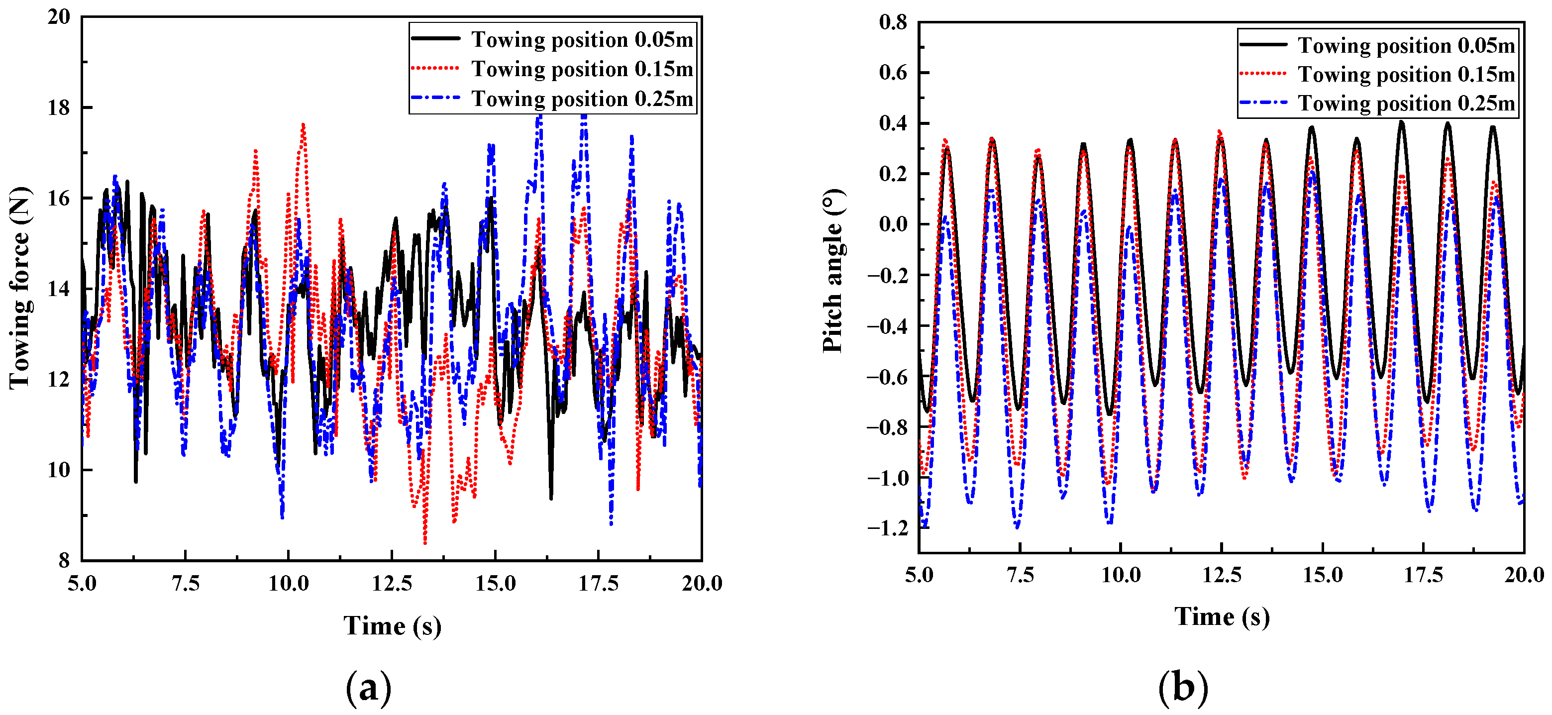
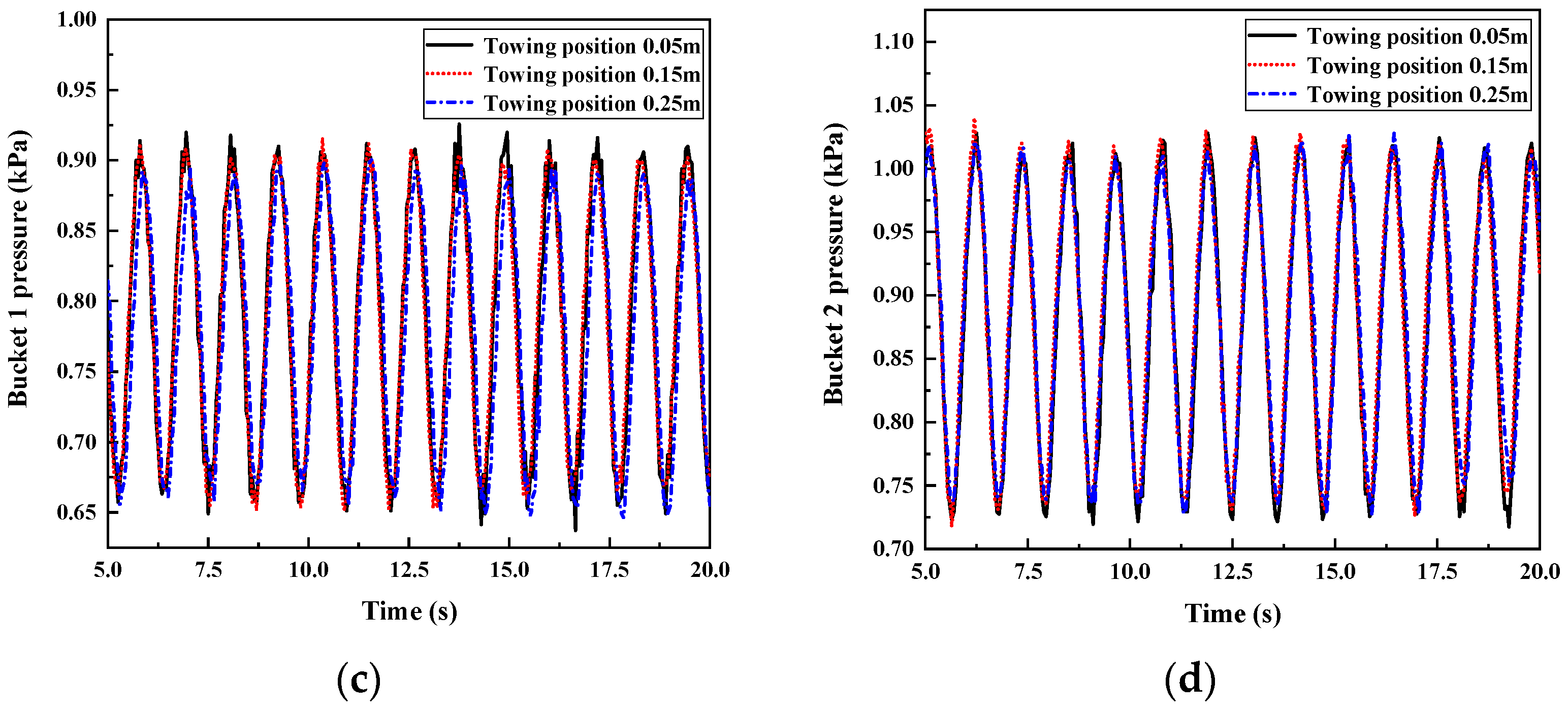
4.1.2. Effect of the Towing Position

In this section, the towing position was considered, and the dynamic response of the TBJF was analyzed. The towing conditions are shown in Table 7. The dynamic response of the TBJF for different towing positions are shown in Figure 17.
As can be seen from Figure 17a, when the draft, towing speed, wave height, and wave period remained unchanged, with the gradual increase in the position height of the towing position, the change range of the towing force of the TBJF increased slightly. However, this was not obvious, which means that the towing force was less affected by the change in the towing position. As shown in Figure 17b, with the gradual increase in the position height of the towing position, the fluctuation range of the pitch increased gradually. This indicates that, when the position height of the towing position increased, the recovery torque, which was provided by the TBJF, decreased. From Figure 17c,d, it can be concluded that changing the towing position had no impact on the pressure in the bucket of the TBJF. In other words, the change in the towing position cannot affect the total buoyancy.

4.2. Effect of the Sea Condition on the TBJF Stability

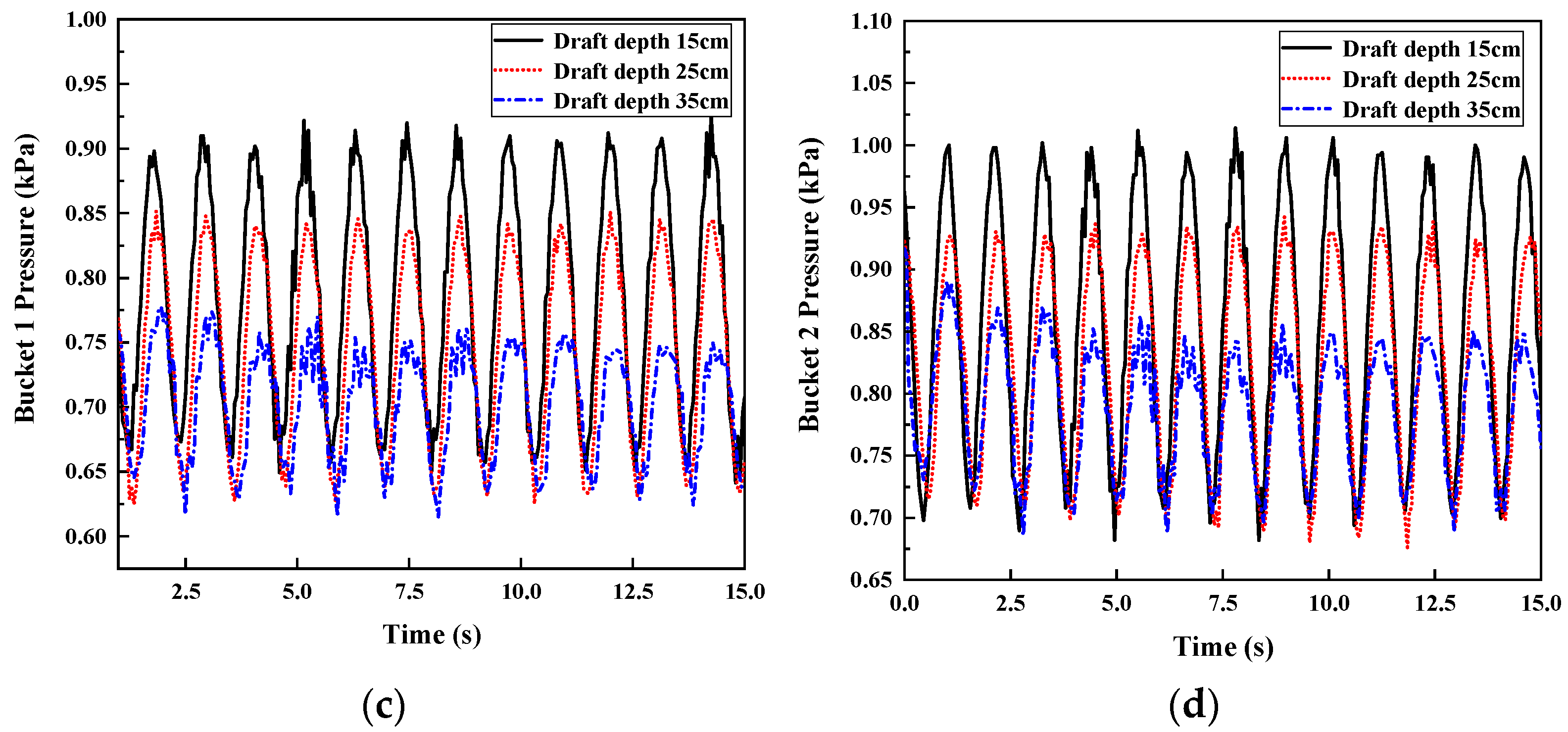
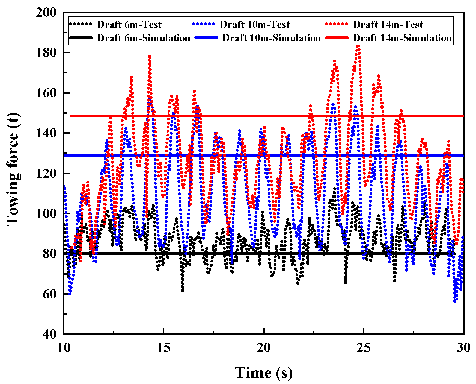
4.2.1. Effect of the Draft Depth

In this section, the effects of the draft depth on and the dynamic response of the TBJF were analyzed. The towing conditions are shown in Table 8. The dynamic response of the TBJF for different draft depths is shown in Figure 18.
As shown in Figure 18a, when the towing speed of the foundation remained unchanged, for hydrostatic water, with the gradual increase in draft depth, the water entry area of the TBJF increased gradually. In addition, the upstream force increased gradually, which increased the towing force. As can be seen from Figure 18b, the fluctuation range for pitch gradually increased with increasing draft depth. This was contrary to the result obtained by the changing draft depths for towing for wave conditions. It can be seen from Figure 18c,d that, for hydrostatic water, with an increase in the draft, the buoyancy provided by the air in the bucket decreased gradually, while the pressure in the bucket decreased gradually. The variations in the pressure in buckets 1, 2, and 3 were almost the same.

4.2.2. Effect of Wave Height

In this section, the effects of wave height on and the dynamic response of the TBJF were analyzed. The towing conditions are shown in Table 9. The dynamic response of the TBJF for different wave heights are shown in Figure 19.
The effect of wave height on the towing force of the TBJF is shown in Figure 19a. It can be seen that increasing wave height can significantly increase the towing force generated by waves. This also leads to a significant increase in the amplitude and fluctuation range of the towing force. In a grade-5 wind and wave environment, the foundation sailed against waves at a speed of around 2.58 knots, and the maximum towing force was about 383.6 T. In the actual towing process, the towing force under the most unfavorable sea conditions should be fully considered, and the tug with appropriate horsepower should be selected. It can also be seen from Figure 19b that, with increasing wave height, the pitch amplitude and fluctuation range increased, which indicates that the towing stability was gradually getting worse. The wave height posed a great impact on the integrated stability and dynamic response of the “Jacket + bucket foundation” composite structure. In the actual project, it is necessary to select an appropriate sea state period for the integrated wet-towing of the foundation. It is recommended to carry out long-distance wet-towing in a grade-5 wind and wave environment. Figure 19c,d shows that the increase in wave height can increase the amplitude and fluctuation range of the pressure in buckets 1 and 2. This indicates that the greater the wave height, the clearer is the change in the liquid level difference, inside and outside the foundation during towing.

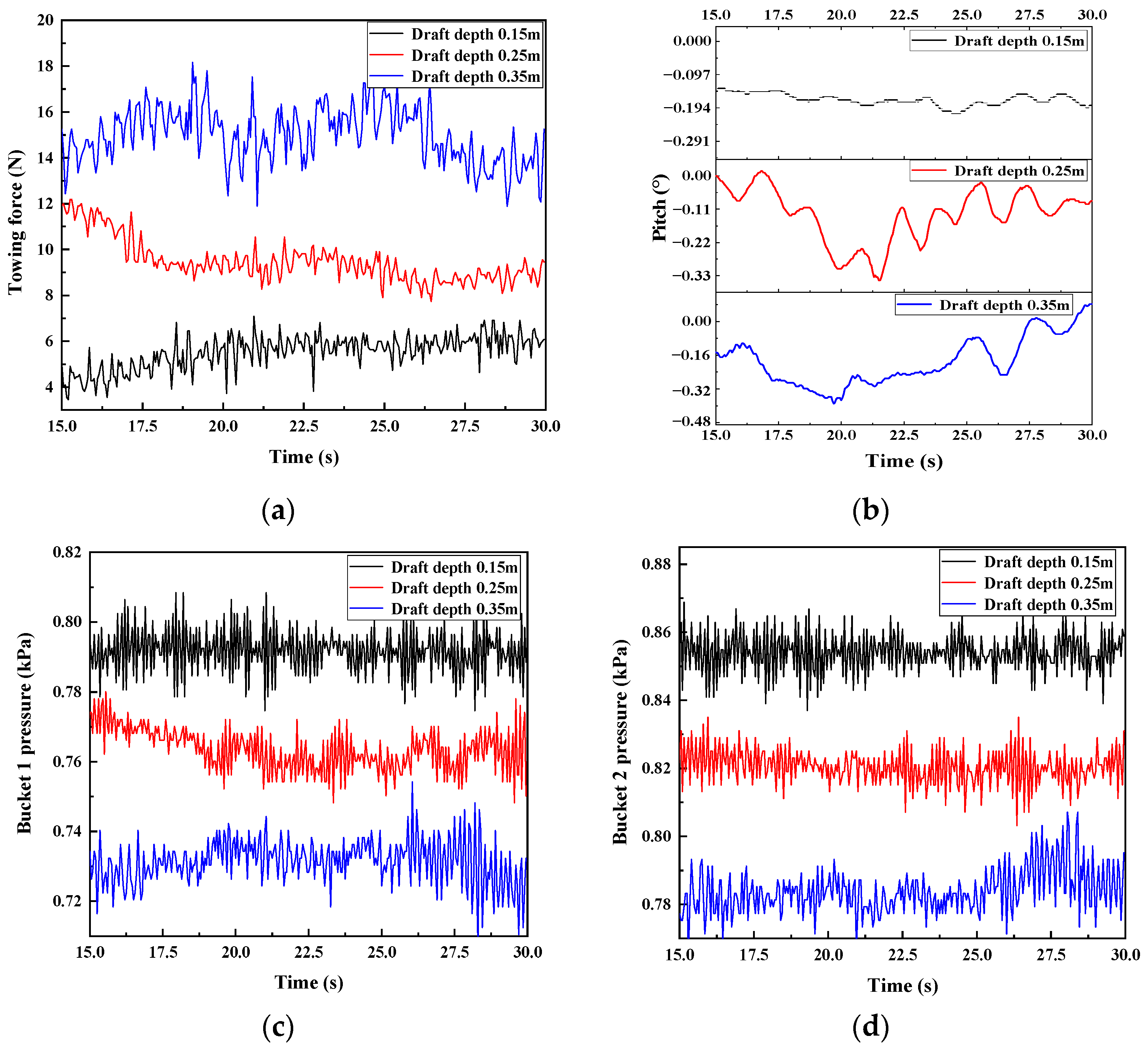
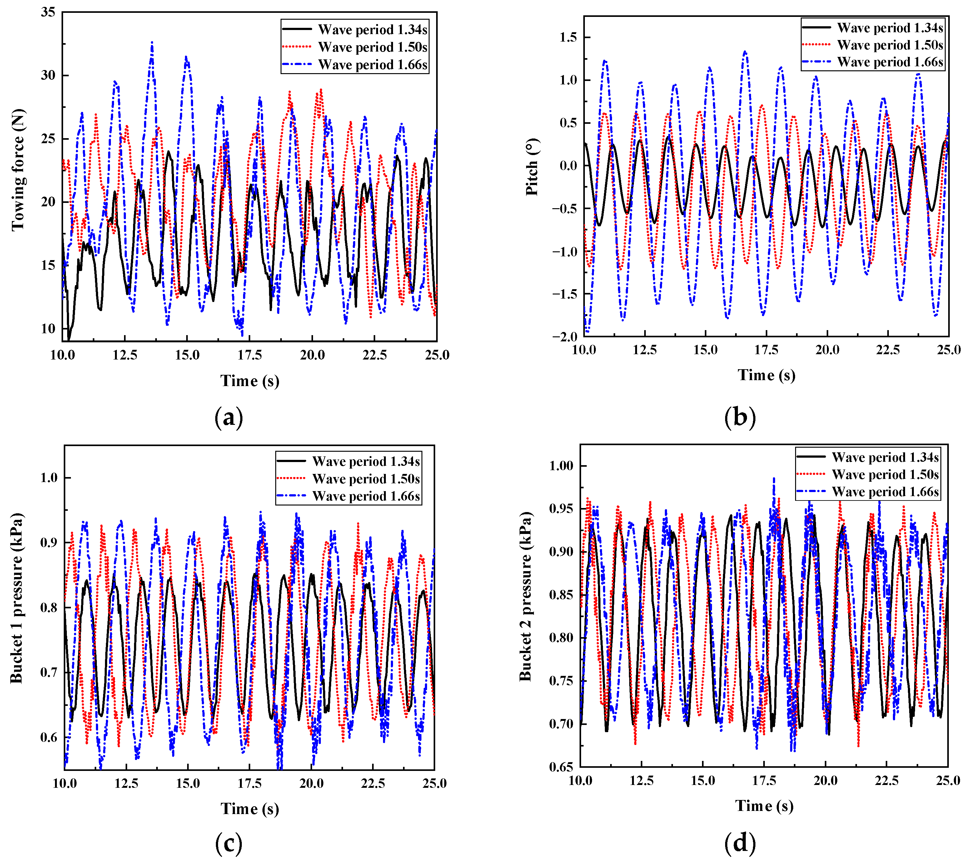
4.2.3. Effect of the Wave Period

The effects of the wave period on and the dynamic response of the TBJF were analyzed. The towing conditions are shown in Table 10. The test results are shown in Figure 20.
The effect of the wave period on the towing force of the TBJF is shown in Figure 20a. It can be seen that, with the gradual increase in the wave period, the amplitude and variation spectrums of the streamer force increased. However, the increased rate of the amplitude of the towing force decreased when the waving period varied from 1.34 s to 1.5 s; correspondingly, the towing force increased by 19%, while the waving period varied from 1.5 s to 1.66 s, only yielding a 13% increase of in the towing force. Similar effects of waving periods on pitch were revealed. This indicates that, when the wave period was close to the natural period, the foundation could produce a large dynamic response, which should be avoided during the wet-towing process. Figure 20c,d shows that increasing the wave period can gradually increase the fluctuation range of the liquid level inside and outside the bucket during towing. As a result, the gradual increase in the variation range for the pressure in the buckets can occur. Almost similar bucket pressures were found among buckets 1, 2, and 3.

5. Conclusions

In this study, the static stability of a triple-bucket jacket foundation (TBJF) for different draft depths and eccentric loads was evaluated through laboratory model tests and numerical simulations. In addition, the wet-towing stability of the TBJF for different wet-towing modes and sea conditions was investigated. The main conclusions were drawn:
  • The “Jacket + triple-bucket foundation” composite structure performs good self-stability. With increasing draft depth, the additional water mass of the structure, the natural periods of heave and roll for the TBJF increased, and the maximum difference of results between the test and the simulation was within 10%. A greater eccentric load led to a higher roll and pitch, and the maximum difference of results between the test and the simulation was within 20%.
  • The integrated long-distance wet-towing of the “Jacket + triple-bucket foundation” composite structure was applicable. With increasing draft depth, the towing resistance increased, while the pitch and the air pressure in each bucket decreased. A 10-m (half-bucket high) draft depth is recommended for the integrated wet-towing of the foundation. With the increase in the height of the towing position, the towing force increased slightly, and the fluctuation range of pitch increased. This had a negligible effect on the air pressure in the buckets.
  • The wave height poses a great impact on the integrated stability and dynamic response of the “Jacket + triple-bucket foundation” composite structure. With increasing wave height, the forward speed of the TBJF during the towing process decreased. In addition, the amplitude and variation range for the towing force as well as the pitch and the air pressure in each bucket increased. The towing stability became worse. It is recommended to carry out long-distance wet-towing within a 2-m wave height and a grade-5 wind and wave environment.
  • The maximum towing force was revealed rarely beyond 385 knots when the TBJF was towed at a speed of around 2.58 knots against waves under conditions of a grade-5 wind and wave environment. In the actual towing process, the towing force under the most unfavorable sea conditions should be fully considered, and the tug with appropriate horsepower should be selected.
  • When the wave period is close to the structural natural period and the wave height is large, the structural resonance and destructive dynamic response of TBJF may occur, which should be avoided in engineering practice.

Author Contributions

Conceptualization, H.W. and Y.G.; methodology, C.Y. and Y.G.; validation, C.Y., Z.W. and X.L.; formal analysis, C.Y. and Y.G.; writing—original draft preparation, C.Y., Z.W. and X.L.; writing—review and editing, Y.G., C.Y. and H.W.; supervision, H.W. and Y.G.; project administration, H.W. and Y.G.; funding acquisition, H.W. and Y.G. All authors have read and agreed to the published version of the manuscript.

Funding

This research was funded by the National Science Foundation of China with grant no. 51909188.

Conflicts of Interest

The authors declare no conflict of interest.

References

  1. Willis, D.J.; Niezrecki, C.; Kuchma, D.; Hines, E.; Arwade, S.R.; Barthelmie, R.J.; DiPaola, M.; Drane, P.J.; Hansen, C.J.; Inalpolat, M.; et al. Wind energy research: State-of-the-art and future research directions. Renew. Energy 2018, 125, 133–154. [Google Scholar] [CrossRef]
  2. Chang, V.; Chen, Y.; Zhang, J.; Qianwen, A.X.; Baudier, P.; Liu, B.S.C. The market challenge of wind turbine industry-renewable energy in PR China and Germany. Technol. Forecast. Soc. Chang. 2021, 2021, 166. [Google Scholar] [CrossRef]
  3. Carswell, W.; Johansson, J.; Løvholt, F.; Arwade, S.R.; Madshus, C.; DeGroot, D.J.; Myers, A.T. Foundation damping and the dynamics of offshore wind turbine monopoles. Renew. Energy 2015, 80, 724–736. [Google Scholar] [CrossRef]
  4. Gasparatos, A.; Doll, C.N.H.; Esteban, M.; Ahmed, A.; Olang, T.A. Renewable energy and biodiversity: Implications for transitioning to a Green Economy. Renew. Sustain. Energy Rev. 2017, 70, 161–184. [Google Scholar] [CrossRef] [Green Version]
  5. Zaaijer, M.B. Foundation modelling to assess dynamic behavior of offshore wind turbines. Appl. Ocean Res. 2006, 28, 45–57. [Google Scholar] [CrossRef]
  6. Guo, Y.; Zhang, P.; Ding, H.; Le, C. Design and verification of the loading system and boundary conditions for wind turbine foundation model experiment. Renew. Energy 2021, 172, 16–33. [Google Scholar] [CrossRef]
  7. Lee, J.; Zhao, F. Global Wind Report 2021; GWEC: Brussels, Belgium, 2021. [Google Scholar]
  8. Wang, X.; Zeng, X.; Li, J.; Yang, X.; Wang, H. A review on recent advancements of substructures for offshore wind turbines. Energy Convers. Manag. 2018, 158, 103–119. [Google Scholar] [CrossRef]
  9. Mo, R.; Cao, R.; Liu, M.; Li, M.; Huang, Y. Seismic fragility analysis of monopile offshore wind turbines considering ground motion directionality. Ocean Eng. 2021, 235, 109414. [Google Scholar] [CrossRef]
  10. Lu, W.; Zhan, G.; Wang, A. Bearing behavior of multiple piles for offshore wind driven generator. Ocean Eng. 2017, 129, 538–548. [Google Scholar] [CrossRef]
  11. Zhang, H.; Liang, F.; Zheng, H. Dynamic impedance of monopiles for offshore wind turbines considering scour-hole dimensions. Appl. Ocean Res. 2021, 107, 102493. [Google Scholar] [CrossRef]
  12. He, R.; Wang, L. Elastic rocking vibration of an offshore Gravity Base Foundation. Appl. Ocean Res. 2016, 55, 48–58. [Google Scholar] [CrossRef]
  13. Wen, K.; Wu, X.; Zhu, B. Numerical investigation on the lateral loading behaviour of tetrapod piled jacket foundations in medium dense sand. Appl. Ocean Res. 2002, 100, 102198. [Google Scholar]
  14. Jiang, J.; Jian, J.; Dong, X.; Wang, H.; Zhou, H. Soil damping calculation of the offshore wind turbine supported by wide-shallow bucket foundation. Appl. Ocean Res. 2021, 111, 102682. [Google Scholar] [CrossRef]
  15. Ningxin, Y.; Zhou, M.; Tian, Y.; Zhang, X. Evaluation of capacities of bucket foundations in soft-stiff-soft clays under combined loading. Appl. Ocean Res. 2021, 115, 102843. [Google Scholar]
  16. Yan, Y.; Bashir, M.; Michailides, C.; Mei, X.; Wang, J.; Li, C. Coupled analysis of a 10 MW multi-body floating offshore wind turbine subjected to tendon failures. Renew. Energy 2021, 176, 89–105. [Google Scholar]
  17. Hegseth, J.M.; Bachynski, E.E.; Leira, B.J. Effect of environmental modelling and inspection strategy on the optimal design of floating wind turbines. Reliab. Eng. Syst. Safety 2021, 214, 107706. [Google Scholar] [CrossRef]
  18. Antoniou, M.; Gelagoti, F.; Anastasopoulos, I. A compliant guyed system for deep-sea installations of offshore wind turbines: Concept, design insights and dynamic performance. Soil Dyn. Earthq. Eng. 2019, 119, 235–252. [Google Scholar] [CrossRef]
  19. Lu, J.; Zhang, Y.; Ren, M. Grouting Technology of Gravity Base for Offshore Wind Power. Electr. Power Constr. 2012, 33, 95–98. [Google Scholar]
  20. Cao, C. Study on Design Methods of Monopile Supporting Structure and Foundation for Offshore Wind Energy Converters. Mech. Electr. Equip. 2018, 35, 39–50. [Google Scholar]
  21. He, Y.S.; Wang, J.F.; Zhao, H.Y.; Li, Z.L.; Xing, K.Y.; Yao, S.K.; He, Z.J. Research of load calculation and load combination for wind turbine generator system of beach-shallow sea. Build. Struct. 2012, 42, 412–418. [Google Scholar] [CrossRef]
  22. Natarajan, A.; Stolpe, M.; Wandji, W.N. Structural optimization based design of jacket type sub-structures for 10 MW offshore wind turbines. Ocean Eng. 2019, 172, 629–640. [Google Scholar] [CrossRef]
  23. Ku, C.-Y.; Chien, L.-K. Modeling of Load Bearing Characteristics of Jacket Foundation Piles for Offshore Wind Turbines in Taiwan. Energies 2016, 9, 625. [Google Scholar] [CrossRef]
  24. Ding, H.; Peng, Y.; Zhang, P.; Zhai, H.; Jia, N. Model Tests on the Penetration Resistance of Bucket Foundations for Offshore Wind Turbines in Sand. Mar. Sci. Technol. 2020, 8, 368. [Google Scholar] [CrossRef]
  25. Jiang, X. Analysis on Bearing Capacity of Wide and Shallow Bucket Foundation in Silty Clay; Tianjin University: Tianjin, China, 2016. [Google Scholar]
  26. Ehrmann, A.; Penner, N.; Gebhardt, C.G.; Rolfes, R. Offshore Support Structures with Suction Buckets: Parameter Fitting of a Simplified Foundation Model. In Proceedings of the International Ocean and Polar Engineering Conference, ISOPE, Rhodes, Greece, 26 June–1 July 2016. [Google Scholar]
  27. Guo, J. Offshore Installation of the First Suction Tube Jacket Fan Foundation in China. Available online: https://tech.sina.com.cn/roll/2020-08-10/doc-iivhvpwy0173652.shtml (accessed on 10 August 2020).
  28. DONG Energy. Suction Bucket Jacket Foundation Installed at Borkum Riffgrund 1 (Gallery). Available online: https://www.offshorewind.biz/2014/08/28/suction-bucket-jacket-foundation-installed-at-borkum-riffgrund-1-gallery/ (accessed on 15 March 2021).
  29. SPT Offshore. AOWF Suction Bucket Tests Jackets. Available online: https://www.sptoffshore.com/projects/aowf-suction-bucket-tests-jackets-with-suction-pile-foundations/ (accessed on 21 March 2021).
  30. Achmus, M.; Schroeder, C. Installation and bearing behaviour of bucket foundations for offshore structures. Bautechnik 2014, 91, 597–608. [Google Scholar] [CrossRef]
  31. Kishimoto, T.; Kijima, K. The manoeuvring characteristics on tug-towed sip systems. In Proceedings of the Control Applications in Marine Systems, Glasgow, Scotland, UK, 18–20 July 2001. [Google Scholar]
  32. Park, S.H.; Lee, S.J.; Lee, S. Experimental investigation of towing- and course-stability of a FPSO towed by a tug-boat with lateral motion. Int. J. Nav. Archit. Ocean Eng. 2021, 13, 12–13. [Google Scholar] [CrossRef]
  33. Zeng, G.; Zhu, J.; Shao, Y.; Wen, J. The nonlinear dynamics model of towed cable-ship and numerically simulation. J. Nav. Univ. Eng. 2006, 18, 96–101. [Google Scholar]
  34. Charters, S.; Thomas, L.; Latorre, R. Analysis of towed vessel course stability in shallow water. Marit. Tech. Inf. Facility 1986, 128, 12–16. [Google Scholar]
  35. Varyani, K. Course Stability Problem Formulation. In Proceedings of the Gdansk Poland: 13th International Conference on Hydrodynamic in Ship Design (HYDRONAV 99), 2nd International Symposiums on Ship Manoeuvring(MANOEUVRING 99), Ostróda, Poland, 22–24 September 1999. [Google Scholar]
  36. Van Kessel, J.L.F. Aircushion Supported Mega-Floaters; Wöhrmann Print Service: Zutphen, The Netherlands, 2010; pp. 110–154. [Google Scholar]
  37. Chenu, B.; Morris, T.; Thiagarajan, K.P. Some hydrodynamic characteristics of an air-cushion supported concrete gravity structure. In Proceedings of the 15th Australasian Fluid Mechanics Conference, Sydney, Australia, 13–17 December 2004. [Google Scholar]
  38. Ikoma, T.; Masuda, K.; Maeda, H. Hydroelastic Behavior of Air-Supported Flexible Floating Structures. In Proceedings of the 21st International Conference on OMAE’02, Oslo, Norway, 23–28 June 2002. [Google Scholar]
  39. Ohkusu, M. Wave effects on multiple bodies. Hydrodyn. Ship Ocean Eng. 2001, 3, 3–26. [Google Scholar]
  40. Wind Turbines—Part I: Design Basis and Qualification Process. In Proceedings of the ASME 2009 28th International Conference on Ocean, Offshore and Arctic Engineering, American Society of Mechanical Engineers. Honolulu, HI, USA, May 2009; pp. 845–853.
  41. Roddier, D.; Cermelli, C.; Aubault, A.; Weinstein, A. WindFloat: A floating foundation for offshore wind turbines. J. Renew. Sustain. Energy 2010, 2, 3041–3045. [Google Scholar] [CrossRef]
  42. ELISA—Elican Project, World´S First Cranesless Bottom-Fixed Offshore Turbine. 5mw “Elisa” Prototype. Available online: https://www.esteyco.com/proyectos/elisa-elican-project/ (accessed on 5 February 2021).
  43. Yu, T.; Lian, J.; Shi, Z.; Wang, H. Experimental investigation of current-induced local scour around composite bucket foundation in silty sand. Ocean Eng. 2016, 117, 311–320. [Google Scholar] [CrossRef]
  44. Liu, M.; Lian, J.; Yang, M. Experimental and numerical studies on lateral bearing capacity of bucket foundation in saturated sand. Ocean Eng. 2017, 144, 14–20. [Google Scholar] [CrossRef]
  45. Jia, N.; Zhang, P.; Liu, P.; Ding, H. Bearing capacity of composite bucket foundations for offshore wind turbines in silty sand. Ocean Eng. 2019, 12, 2487. [Google Scholar] [CrossRef]
  46. Wang, X.; Zhang, P.; Ding, H.; Liu, R. Experimental study of the accumulative deformation effect on wide-shallow composite bucket foundation for offshore wind turbines. J. Renew. Sustain. Energy 2017, 9, 063306. [Google Scholar] [CrossRef]
Figure 1. Global installed capacity of offshore wind power.
Jmse 09 01152 g001
Figure 2. The most common foundation types around the globe.
Jmse 09 01152 g002
Figure 3. Manufacturing and dry-towing process.
Jmse 09 01152 g003
Figure 4. Manufacturing and wet-towing.
Jmse 09 01152 g004
Figure 5. Schematic diagram of the prototype. (a) Overall view. (b) Top view.
Jmse 09 01152 g005
Figure 6. Schematic diagram of the test model. (a) TBJF model. (b) Schematic diagram of the TBJF.
Jmse 09 01152 g006
Figure 7. Schematic illustrating the static stability test.
Jmse 09 01152 g007
Figure 8. Schematic illustrating the wet-towing stability test.
Jmse 09 01152 g008
Figure 9. Natural period for the heave of different drafts. (a) Acceleration of heave variation. (b) Spectrum diagram of heave variation.
Jmse 09 01152 g009
Figure 10. Natural period of roll for different drafts. (a) Roll attenuation curve. (b) Spectrum diagram of roll attenuation.
Jmse 09 01152 g010
Figure 11. SESAM model of TBJF.
Jmse 09 01152 g011
Figure 12. Comparison of test and simulation results. (a) Natural period of heave. (b) Natural period of roll.
Jmse 09 01152 g012
Figure 13. Pitch and roll for the eccentric load. (a) Pitch. (b) Roll.
Jmse 09 01152 g013
Figure 14. Comparison of test and simulation of restoring arm.
Jmse 09 01152 g014
Figure 15. The dynamic response of the TBJF for different draft depths. (a) Towing force. (b) Pitch. (c) Bucket 1 pressure. (d) Bucket 2 pressure.
Jmse 09 01152 g015aJmse 09 01152 g015b
Figure 16. Comparison of test and simulation of towing force.
Jmse 09 01152 g016
Figure 17. Dynamic response of the TBJF for different towing positions. (a) Towing force. (b) Pitch. (c) Bucket 1 pressure. (d) Bucket 2 pressure.
Jmse 09 01152 g017aJmse 09 01152 g017b
Figure 18. The dynamic response of the TBJF for different draft depths. (a) Towing force. (b) Pitch. (c) Bucket 1 pressure. (d) Bucket 2 pressure.
Jmse 09 01152 g018
Figure 19. The dynamic response of the TBJF for different wave heights. (a) Towing force. (b) Pitch. (c) Bucket 1 pressure. (d) Bucket 2 pressure.
Jmse 09 01152 g019
Figure 20. The dynamic response of the TBJF for different wave periods. (a) Towing force. (b) Pitch. (c) Bucket 1 pressure. (d) Bucket 2 pressure.
Jmse 09 01152 g020
Table 1. Proportional relationship between model and prototype.
ItemsSymbolRatioItemsSymbolRatio
Line scaleLs/LmλPeriod, speedTs/Tm, Vs/Vmλ0.5
AreaAs/Amλ2Frequencyfs/fmλ0.5
VolumeVs/Vmλ3Masss/∆mγλ3
Linear accelerationas/am1ForceFs/Fmγλ3
Angleθsm1MomentMs/Mmγλ4
Water densityρsmγMoment of inertiaIs/Imγλ5
Table 2. Dimensions of the test model.
Diameter
D/m
Skirt Length
L/m
CoG Heights
H/m
Self-Weight
G/kg
Prototype202029.74
Model0.50.50.742648.43
Table 3. Draft depths used for the TBJF.
ConditionDraft DepthAir RatioWater Ratio
115 cm86.3%13.7%
225 cm66.3%33.7%
335 cm46.3%53.7%
Table 4. The natural period of heave for different drafts.
Draft Depth15 cm25 cm35 cm
Natural frequency of heave (Hz)1.020.850.7
Natural period of heave (s)0.981.181.4
Table 5. Natural period of roll for different drafts.
Draft Depth15 cm25 cm35 cm
Natural frequency of heave (Hz)0.640.60.56
Natural period of heave (s)1.561.671.78
Table 6. Towing conditions for different draft depths.
ItemsCondition 1Condition 2Condition 3
Wave height (H/cm)2.52.52.5
Wave period (T/s)1.341.341.34
Towing speed (V/knots)0.410.410.41
Draft depth (h1/m)0.150.250.35
Towing position (ht/m)0.050.050.05
Table 7. Towing conditions of different towing positions.
ItemsCondition 1Condition 2Condition 3
Wave height (H/cm)2.52.52.5
Wave period (T/s)1.341.341.34
Towing speed (V/knots)0.410.410.41
Draft depth (h1/m)0.150.150.15
Towing position (ht/m)0.050.150.25
Table 8. Towing conditions of different draft depths.
ItemsCondition 1Condition 2Condition 3
Towing speed (V/knots)0.410.410.41
Draft depth (h1/m)0.150.250.35
Towing position (ht/m)0.050.050.05
Table 9. Towing conditions of different wave heights.
ItemsCondition 1Condition 2Condition 3
Wave height (H/cm)2.53.755
Wave period (T/s)1.341.341.34
Towing speed (V/knots)0.410.410.41
Draft depth (h1/m)0.250.250.25
Table 10. Towing conditions for different wave periods.
ItemsCondition 1Condition 2Condition 3
Wave height (H/cm)2.52.52.5
Wave period (T/s)1.341.501.66
Towing speed (V/knots)0.410.410.41
Draft depth (h1/m)0.250.250.25
Publisher’s Note: MDPI stays neutral with regard to jurisdictional claims in published maps and institutional affiliations.

