Article

Dynamic Stability of an Ocean Current Turbine System

1
Department of Mechanical Engineering, Kun Shan University and Green Energy Technology Research Centre (GETRC), Tainan 710303, Taiwan
2
Department of Marine Environment and Engineering, National Sun Yat-sen University, Kaohsiung 80424, Taiwan
3
Marine Science and Information Research Center, National Academy of Marine Research, Kaohsiung 80661, Taiwan
*
Author to whom correspondence should be addressed.
J. Mar. Sci. Eng. 2020, 8(9), 687; https://doi.org/10.3390/jmse8090687
Submission received: 8 July 2020 / Revised: 1 September 2020 / Accepted: 1 September 2020 / Published: 6 September 2020
(This article belongs to the Special Issue Waves and Ocean Structures)

Abstract

:
This paper presents a theoretical solution for the dynamic stability of the ocean current turbine system developed in Taiwan. This system is tethered to the sea floor and uses the Kuroshio Current to produce electricity. To maintain the performance of the turbine system in the presence of the Kuroshio Current, the stability of the surfaced turbine needs to be considered. The proposed system is composed of a turbine, a buoyance platform, a traction rope, and a mooring foundation. The two-dimensional theoretical solutions treat the turbine as a rigid body with a movable structure that is moored with two cables. In this model, the gravity, buoyancy, and drag force generated by the wave on the turbine structure are considered. In addition, an analytical solution is proposed for the general system. Finally, the effects of the wave on the pitch motion and dynamical stability of the ocean current turbine system are investigated.

1. Introduction

The application of traditional energy resources (e.g., fossil fuels) causes serious environmental pollution. Renewable energy resources, such as wind, sunlight, ocean currents, waves, and tidal current, have been introduced as alternatives for achieving a low-carbon society. Ocean current energy is a potential power source that must be developed. Various forms of ocean energy are being investigated as potential sources of power generation [1,2,3,4]. For example, the Kuroshio Current—a strong current passing through the east of Taiwan—is expected to be an excellent energy resource. It has a mean velocity of 1.2–1.53 m/s near the surface and the potential electricity capacity of the Taiwan Current is approximately 4 GW [5]. This ocean energy source is stable and abundant, with the potential to be developed and utilized.
Tidal current—which can be extracted from the rise and fall of sea levels under the gravitational force exerted by the Moon and Sun as well as Earth’s rotation—is one of the most valuable resources. Moreover, tidal current energy is more predictable than wind and wave energies [6]. Tidal current turbine (TCT) can be categorized into horizontal- and vertical-axis tidal turbines [7,8]. These inventions can harness the kinetic energy of tides and principally convert it to electricity. Horizontal-axis TCTs are the most common device, with their rotation axis parallel to the current stream direction [9,10]. By contrast, vertical-axis TCTs rotate about a vertical axis perpendicularly to the current stream [11]. Chen and Lam [6] reviewed the survivability of tidal power devices used to harness tidal power.
Zhou et al. [7] presented up-to-date information on large tidal turbine projects with a power exceeding 500 kW as well as their achievements and development histories. Most industrialized marine current turbine (MCT) devices are horizontal-axis turbines, with the rotation axis parallel to the current flow direction. The main disadvantages associated with vertical-axis turbines include their relatively low self-starting capability, high torque fluctuations, and generally lower efficiency than horizontal-axis turbines. The power of industrialized MCT devices rigidly fixed at a seabed below 80 m depth, such as Atlantis AR1000 turbine, Voith Hydro turbine, and GE-Alstom tidal turbine, is over 1 MW at a current speed of approximately 2.4–4 m/s. These are called seabed-mounted turbines. Some devices, such as the Scotrenewables SR250 turbine and Ocean Renewable Power Company (ORPC) turbine, are flexibly moored at deep seabeds.
A flexible moored device is an important tool for deployment in deep water. The majority of moored tidal current turbine developers agree that by using a flexibly moored system, the device will be automatically self-aligned to the direction of current flow [7,12,13,14,15]. A traditional design uses the gravity foundations or piles in deep water, which are complex and expensive. The flexible mooring lines and anchors can be deployed in deep water, where the other designs may by impractical [16]. Thus, it is important to develop a mathematical model for a flexible mooring system for ocean current energy systems. Muliawan et al. [17] determined the extreme responses in the mooring lines of a two-body floating wave energy converter with four catenary cables. Angelelli et al. [18] investigated the behavior of a wave energy convertor mooring system with four spread cables by using Ansys AQWA software. Chen et al. [4] investigated the wave-induced motions of a floating wave energy converter (WEC) with mooring lines by using the smoothed particle hydrodynamics method. Davidson and Ringwood [19] reviewed the mathematical models for wave energy convertor mooring systems. The marine energy developer Minesto [20] developed a floating subsea kite with flexible mooring.
Cribbs [7] proposed a conceptual design for the flexible mooring of a current turbine fixed to a 300-m-deep seabed. The system included a mooring chain, a mooring line, a flounder plate, two lines for the turbine and the platform, a marine turbine, and a rotating turbine using blade-estimated airfoils. However, this system has not been practically applied thus far. Chen et al. [4] successfully moored a 50 kW ocean current turbine supplied by Wanchi Company to an 850-m-deep seabed at the offshore area of Pingtung County, Taiwan. At a current speed of 1 m/s, the output power of the system was 26 kW. IHI and NEDO [21] conducted a demonstration experiment of the ocean current turbine located off the coast of Kuchinoshima Island, Kagoshima Prefecture, and obtained data for commercialization; the demonstration experiment was conducted for seven days. The turbine comprised a combination of three cylindrical floats, called pods, having a total length of approximately 20 m, width of approximately 20 m, and turbine rotor diameter of approximately 11 m. The turbine system was moored from the anchor installed on a 100-m-deep seabed.
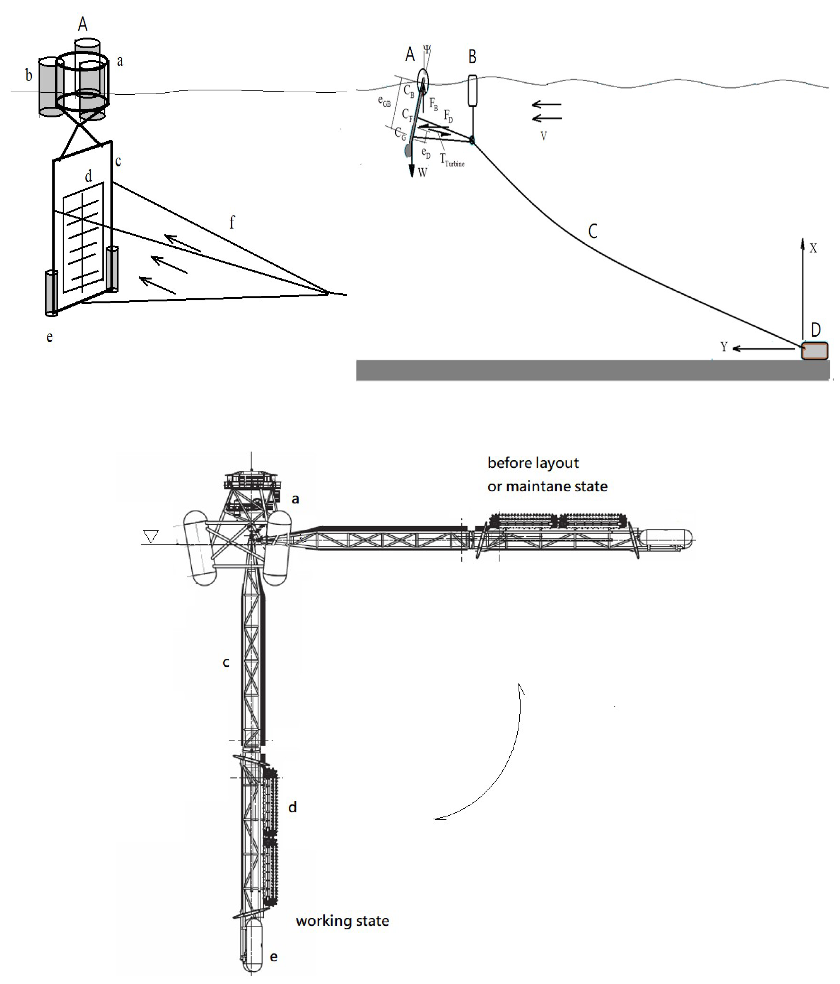
Besides the current rotating-type turbine, the Wanchi Company is also developing an ocean current turbine with a translational blade. To produce more power from the ocean, it is configured with several matrix-array turbines. The system comprises a turbine, a buoyance platform, a traction rope, and a mooring foundation, as shown in Figure 1. The ocean current turbine is tethered to an ~900-m-deep seabed and the ocean current flows perpendicular to the turbine plane. This system might be more unstable than the horizontal rotational turbine. The system is composed of a turbine, a buoyance platform, a traction rope, and a mooring foundation. The system stability is important for the practical operation. So far, only a few studies have investigated the stability of the ocean current turbine system. No literature is devoted to the mathematical model of the system about the coupled heaven, surge and pitch motions. No analytical solution of the system is also presented. Because the system must be sufficiently stable under the effect of wave, the mathematical model is developed and the analytical solutions are presented in this study. Moreover, the effects of several parameters on the system stability are investigated.
In Section 2, a two-dimensional model for the motions of the ocean current turbine system and floater is developed. The turbine system and floater are treated as rigid bodies and the cables are divided into two sections. Theoretical solutions of the motions are presented in Section 3. As detailed in Section 4, a series of simulations were conducted for evaluating the dynamic stability of the system under various wave conditions. Section 5 summarizes the present study and provides some concluding remarks.

2. Governing Equations

According to 
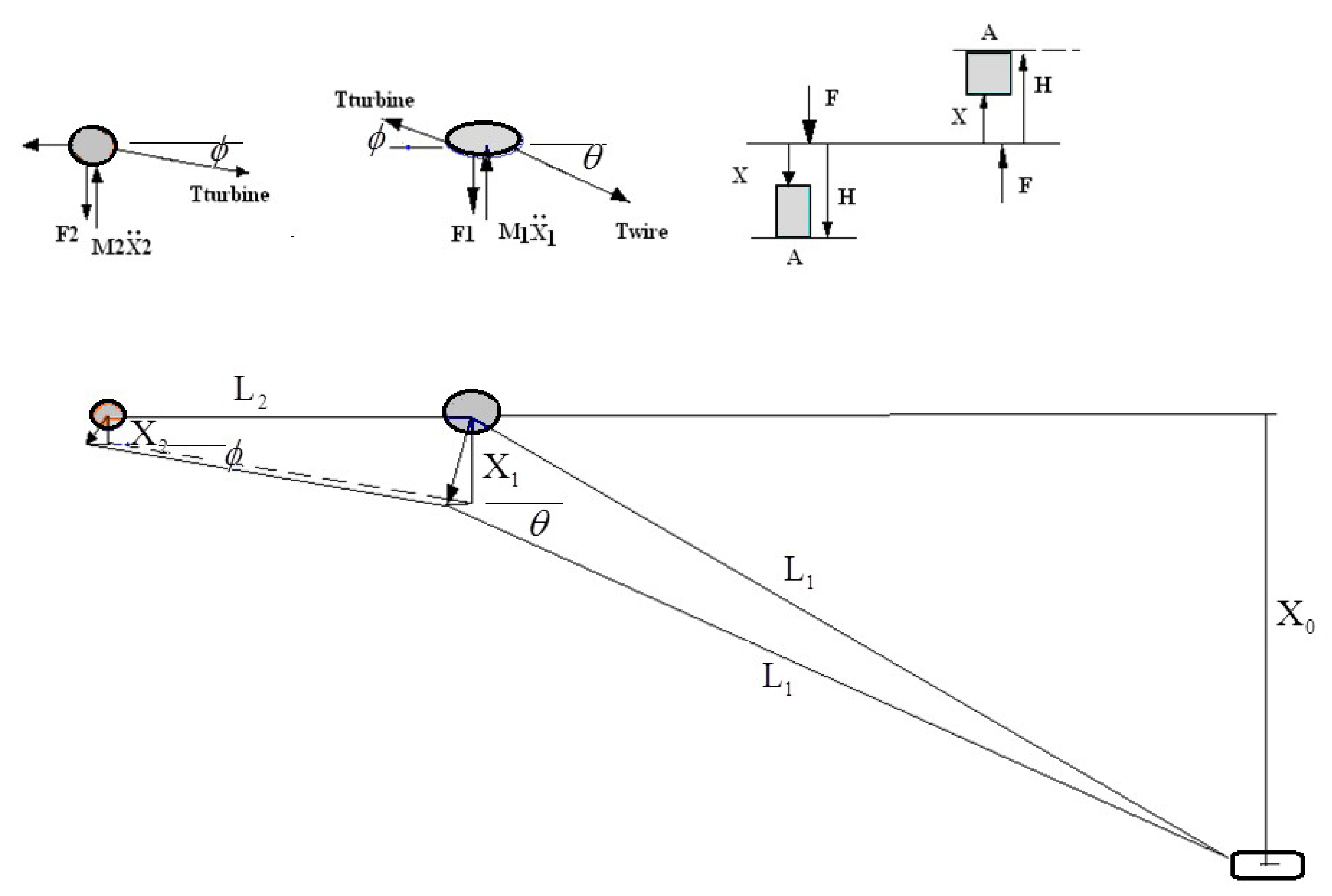
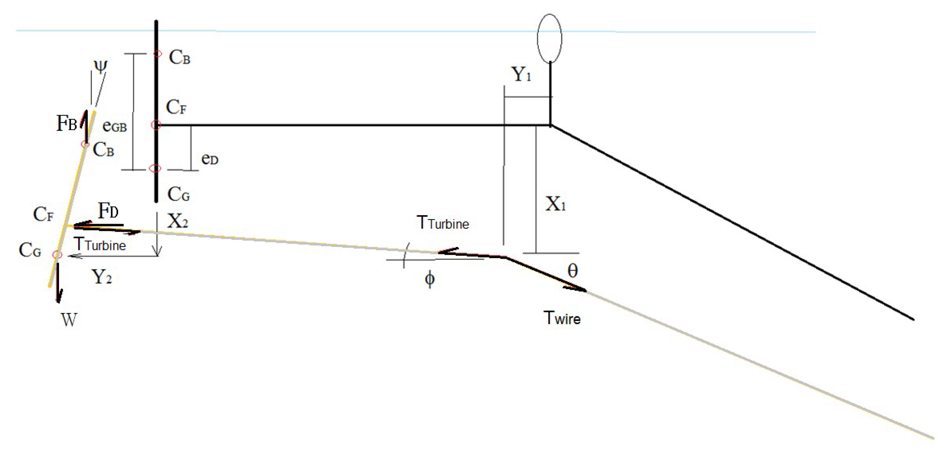
Figure 1, the analysis of the motion and dynamic stability of the ocean current turbine system with a flexible mooring cable is complex. Assume that the structures of turbine and carrier subjected the force due to wave and current are kept during the motion. Because the displacement and pitching motion of the system are significantly concerned, these two components are considered rigid bodies. Moreover, the inertia effect of the elastic cable is neglected. Therefore, the system is simulated as a discrete one. The overall system comprises an anchored mooring, a carrier, and a vertical ocean turbine system driven by a translational blade with a gravity anchor. A mooring system that comprises a long main cable with a sub-cable connecting the carrier and ocean turbine is deployed. Due to the complexity of system stability, the flow field is considered to be in steady state and the ocean current velocity is assumed to be constant and uniform. The horizontal force applied to the turbine and its structure during electricity generation is also assumed to be constant. The coupled motion of the system includes the horizontal, vertical, and pitching oscillations. As shown in Figure 2 and Figure 3, owing to the wave fluctuation, the buoyance forces applied on the floating platform and turbine can be expressed as follows:
F B 1 = ( H 1 X 1 ) A 1 ρ g
F B 2 = ( H 2 X 2 ) A 2 ρ g
where the subscripts “1” and “2” denote the carrier and turbine, respectively, and A 1 and A 2 denote the corresponding hydrodynamic areas. The wave heights at the carrier and turbine are H 1 = H 0 sin Ω t and H 2 = H 0 sin ( Ω t + Φ ) , where H 0 is the wave amplitude. ( H i X i , I = 1~2) indicates the vertical displacement, Ω is the wave frequency, and Φ is the phase lag due to the propagation delay from the carrier to the turbine. On the basis of linear wave theory, the phase is expressed as Φ =   k L 2 , where k indicates the wave number, L 2 is the horizontal distance between the carrier and turbine, ρ (=1025 k g m 3 ) is the density of water, and g (=9.81 m s 2 ) is the gravitational acceleration.
According to the static equilibrium, the force in the horizontal direction at the joint o is expressed as follows:
T w i r e cos θ = T t u r b i n e cos ϕ
According to the dynamic equilibrium, the equations of motion of the floating carrier and turbine platform in the vertical direction are expressed as
M 1 X ¨ 1 F B 1 + T t u r sin ϕ T w i r e sin θ = 0
and
M 2 X ¨ 2 F B 2 T t u r sin ϕ = 0
where X ¨ 1 and X ¨ 2 are the vertical accelerations of the floater and turbine, respectively; T t u r is the tension of the wire between the turbine and floater; and T w i r e is that between the cable and anchor. If the vertical displacement is substantially smaller than the connecting cable between the floating and turbine platforms, the angle ϕ is very small, as shown in Figure 2, and can be approximated as follows:
sin ϕ X 1 X 2 L 2
The cable made by polyethylene dyneema connecting the floating platform and mooring foundation is considered. The material is the ultra-high molecular weight polyethylene (UHMWPE). Because the material properties are great strength, light weight and flexible, the mooring cable is likely straight during the turbine subjected to the ocean current force. Moreover, because the vertical displacement is significantly smaller than the water depth, the following approximate relation can be obtained:
sin θ X 0 L 1
Through substituting Equations (3), (6) and (7) into Equations (4) and (5), we obtain the coupled equations of motion in terms of vertical displacements { X 1 , X 2 } for the carrier and turbine:
M 1 X ¨ 1 + [ A 1 ρ g + T t u r 1 L 2 ] X 1 T t u r 1 L 2 X 2 = T t u r X 0 L 1 2 X 0 2 + H 1 A 1 ρ g = T t u r X 0 L 1 2 X 0 2 + A 1 ρ g H 0 sin Ω t
and
M 2 X ¨ 2 T t u r L 2 X 1 + ( A 2 ρ g + T t u r L 2 ) X 2 = A 2 ρ g H = A 2 ρ g H 0 sin ( Ω t + Φ )
Equations (8) and (9) can be expressed as the equation of vertical motion in the matrix form
[ M 1 0 0 M 2 ] [ X ¨ 1 X ¨ 2 ] + [ K 11 K 12 K 21 K 22 ] [ X 1 X 2 ] = [ T T u r X 0 L 1 2 X 0 2 + A 1 ρ g H 0 sin Ω t A 2 ρ g H 0 sin ( Ω t + Φ ) ]
where the first 2 × 2 matrix is the mass one, the second 2 × 2 matrix is the stiffness one, the last term is the forcing one due to the wave and the force of the turbine and
K 11 = A 1 ρ g + T T u r 1 L 2 , K 12 = K 21 = T T u r L 2 , K 22 = A 2 ρ g T T y r L 2 ,
where X0 is the depth of the seabed, {X1, X2} indicate the vertical displacements, Φ is the phase lag angle, and {M1, M2} are the masses.
Because the distance e G B between the centers of gravity and buoyance of the ocean turbine set is almost constant during the pitching motion, the righting moment is ‘ W e G B sin ψ ’ and the heeling angle curve can be expressed as ‘ e G B sin ψ ’. Based on the principle of dynamic equilibrium, the equation of horizontal translational motion for the turbine can be derived
M 2 Y ¨ 2 F D + T t u r b i n e cos ϕ = 0 ,
where F D = C D 1 2 ρ A ( V Y ˙ 2 ψ ˙ l ) 2 . Considering the velocity resulting from the oscillation ( Y ˙ 2 + ψ ˙ l ) < < V , the drag force becomes F D C D 1 2 ρ A ( V 2 2 V ( Y ˙ 2 + ψ ˙ l ) ) .
Because the angle ϕ approaches zero and C D 1 2 ρ A V 2 T t u r b i n e , Equation (11a) becomes equivalent to the equation of horizontal motion:
M 2 Y ¨ 2 + C D ρ A V Y ˙ 2 + C D ρ A V l ψ ˙ = 0
In the dynamic equilibrium equation, the pitching motion of the turbine is expressed as
I ψ ¨ + W e G B sin ψ + F D e D cos ψ = ( T T u r b i n e cos ϕ ) ( e D cos ψ ) ( T T u r b i n e sin ϕ ) ( e D sin ψ )
Considering the pitching angle ψ to be small and based on Equation (6), the equation of the pitching motion becomes
I ψ ¨ C D ρ A V l e D ψ ˙ + [ W e G B + T T u r b i n e e D ( X 1 X 2 L 2 ) ] ψ C D ρ A V e D y ˙ = 0
where y indicates the horizontal displacement, ψ indicates the pitch angle of the turbine, A is the area of drag, CD is the drag coefficient, e G B is the distance between the centers of gravity and buoyance, V is the current velocity, and l is the radius of rotation.

3. Theoretical Solutions

3.1. Solution of the Vertical Motion

The solutions of vertical displacement of the turbine and carrier comprise static and dynamic components and can be expressed as
X 1 ( t ) = X 10 + X 11 ( t ) , X 2 ( t ) = X 20 + X 21 ( t )
where { X 10 , X 20 } are the static displacements and { X 11 , X 21 } are the dynamic displacements. By substituting Equation (13) into Equation (10) and dividing it into the static and dynamic subsystems, we obtain the following:
Static subsystem:
[ K 11 K 12 K 21 K 22 ] [ X 10 X 20 ] = [ T T u r X 0 L 1 2 X 0 2 0 ]
It should be noted that the Equation (14) demonstrates the relation between the vertical displacements of the turbine and carrier and the current velocity without the wave effect.
Dynamic subsystem:
[ M 1 0 0 M 2 ] [ X ¨ 11 X ¨ 21 ] + [ K 11 K 12 K 21 K 22 ] [ X 11 X 21 ] = [ A 1 ρ g H 0 sin Ω t A 2 ρ g H 0 sin ( Ω t + Φ ) ]
It should be noted that the Equation (15) demonstrates the dynamic behavior subjected to the wave effect under the static equilibrium. From Equation (14), the theoretical solutions of the static equilibrium can be easily derived:
X 10 = T T u r X 0 L 1 2 X 0 2 ( K 11 K 12 K 21 K 22 ) ,   X 20 = K 21 K 22 X 10
Further, the harmonic response of the system under the wave effect will be obtained. The solutions of the dynamic state of Equation (15) are assumed as
[ X 11 X 21 ] = [ X 11 c X 21 c ] cos Ω t + [ X 11 s X 21 s ] sin Ω t
Substituting Equation (17) into Equation (15), and after some manipulations, the theoretical solutions of the dynamic state can be derived as follows:
[ X 11 c X 21 c ] = β c | A | [ K 21 K 11 Ω 2 M 1 ] ,
and
[ X 11 s X 21 s ] = 1 | A | [ α ( K 22 Ω 2 M 2 ) β s K 21 α K 12 + β s ( K 11 Ω 2 M 1 ) ] ,
where
| A | = | K 11 Ω 2 M 1 K 12 K 21 K 22 Ω 2 M 2 | , α = A 1 ρ g H 0 , β c = A 2 ρ g H 0 sin Φ , β s = A 2 ρ g H 0 cos Φ .
As the determinant function of the frequency is equal to zero, | A | = 0 , the resonance condition applies. The two resonant frequencies can be derived as
Ω 1 , 2 2 = 1 2 [ ( K 22 M 2 + K 11 M 1 ) ± ( K 22 M 2 + K 11 M 1 ) 2 4 ( K 11 M 1 K 22 M 2 K 12 K 21 M 1 M 2 ) ]
It is well known that if the wave frequency approaches to the natural frequency of the system, the resonance or instability will occur. However, based on Formula (21) one can tune the natural frequencies of system away the wave frequency to avoiding the instability of vertical vibration.

3.2. Solutions of the Horizontal and Pitching Motions

Consider the horizontal and pitching motions of the static and dynamic systems. The solutions of the horizontal displacement and pitching angle are expressed as
y = y 0 + y c cos Ω t + y s sin Ω t ψ = ψ 0 + ψ c cos Ω t + ψ s sin Ω t
where { y 0 , ψ 0 } are the static horizontal translational and pitching displacements without the wave effect { y c , y s , ψ c , ψ s } are the harmonic solutions. By substituting Equation (22) into Equation (11), we can obtain the following two equations:
o 1 y c + o 2 y s + o 3 ψ s = 0
p 1 y s + p 2 y c + p 3 ψ c = 0
where
o 1 = M 2 Ω 2 , o 2 = Ω C D ρ A V , o 3 = Ω C D ρ A V l . p 1 = M 2 Ω 2 , p 2 = Ω C D ρ A V , p 3 = Ω C D ρ A V l .
By Substituting Equations (22) and (13) into Equation (12), after some manipulation, we obtain
W e G B ψ 0 + ( Ω 2 I ψ c Ω C D ρ A V l e D ψ s + T T u r e D ( X 11 c X 21 c L 2 ) ψ 0 + ( W e G B + T T u r e D X 10 X 20 L 2 ) ψ c Ω C D ρ A V e D y s ) cos Ω t + ( Ω 2 I ψ s + Ω C D ρ A V l e D ψ c + T T u r e D ( X 11 s X 21 s L 2 ) ψ 0 + ( W e G B + T T u r e D X 10 X 20 L 2 ) ψ s + Ω C D ρ A V e D y c ) sin Ω t + T T u r e D ( X 11 c X 21 c L 2 ) ψ c 1 + cos 2 Ω t 2 + T T u r e D ( X 11 s X 21 s L 2 ) ψ s 1 cos 2 Ω t 2 + [ T T u r e D ( X 11 s X 21 s L 2 ) ψ c + T T u r e D ( X 11 c X 21 c L 2 ) ψ s ] sin 2 Ω t = 0
Equation (26) indicates that the horizontal and pitching displacements depend on the resonant frequencies Ω and vertical displacements { X 1 , X 2 } , which are time-dependent functions. Therefore, the characteristic equations can be derived using the orthogonality relation of { sin n Ω t , cos m Ω t } as follows:
First, integrating Equation (26) from 0 to period T (= 2 π / Ω ), Equation (26) can be expressed as
q 0 ψ 0 + q 1 ψ c + q 2 ψ s = 0
where
q 0 = W e G B , q 1 = 1 2 T T u r e D ( X 11 c X 21 c L 2 ) , q 2 = 1 2 T T u r e D ( X 11 s X 21 s L 2 ) .
Second, multiplying Equation (26) with cos Ω t and integrating it from 0 to T, Equation (26) can be expressed as
r 0 ψ 0 + r 1 ψ c + r 2 ψ s + r 3 y s = 0
where
r 0 = T T u r e D ( X 11 c X 21 c L 2 ) , r 1 = ( Ω 2 I + W e G B + T T u r e D X 10 X 20 L 2 ) r 2 = Ω C D ρ A V l e D , r 3 = Ω C D ρ A V e D .
Finally, multiplying Equation (26) with sin Ω t and integrating it from 0 to T, Equation (26) can be expressed as
s 0 ψ 0 + s 1 ψ c + s 2 ψ s + s 3 y c = 0
where
s 0 = T T u r e D ( X 11 s X 21 s L 2 ) , s 1 = Ω C D ρ A V l e D , s 2 = ( Ω 2 I + W e G B + T T u r e D X 10 X 20 L 2 ) , s 3 = Ω C D ρ A V e D
Equations (23), (24) and (27)–(29) can be further expressed as
[ 0 0 o 3 o 4 o 5 0 0 p 3 p 4 p 5 q 1 q 2 q 3 0 0 r 1 r 2 r 3 0 r 5 s 1 s 2 s 3 s 4 0 ] [ ψ 0 ψ c ψ s y c y s ] = 0
The eigenvalues of Equation (30a) provide a measure of system stability. These values are characterized using a matrix, which is the Jacobian of the state of the system. The eigenvalues of the matrix are the characteristic roots of the state equation and can be determined using the roots of characteristic equations of the system.
| 0 0 o 3 o 4 o 5 0 0 p 3 p 4 p 5 q 1 q 2 q 3 0 0 r 1 r 2 r 3 0 r 5 s 1 s 2 s 3 s 4 0 | = 0
or
o 3 ( q 1 r 2 s 4 p 5 ) o 4 ( q 1 r 2 s 3 p 5 s 1 r 2 q 3 p 5 ) + o 5 ( q 1 r 2 s 3 p 4 s 1 r 2 q 3 p 4 r 1 q 2 p 3 s 4 ) = 0
From the characteristic Equation (30c), we can determine the system’s resonance under the effects of various environmental parameters.

4. Numerical Results

It is important to design the current turbine system to be stable in order to obtain good performance and control requirement. The theoretical solutions, including static and dynamic stability systems, are introduced in Section 3. Here, the behaviors of the turbines and floaters under the effects of wave and ocean currents are numerically analyzed. Figure 4, Figure 5, Figure 6 and Figure 7 show the effects of wave frequency f, drag force T T u r , and turbine area A 2 on the amplitudes { X 11 , X 21 } of vertical vibration.
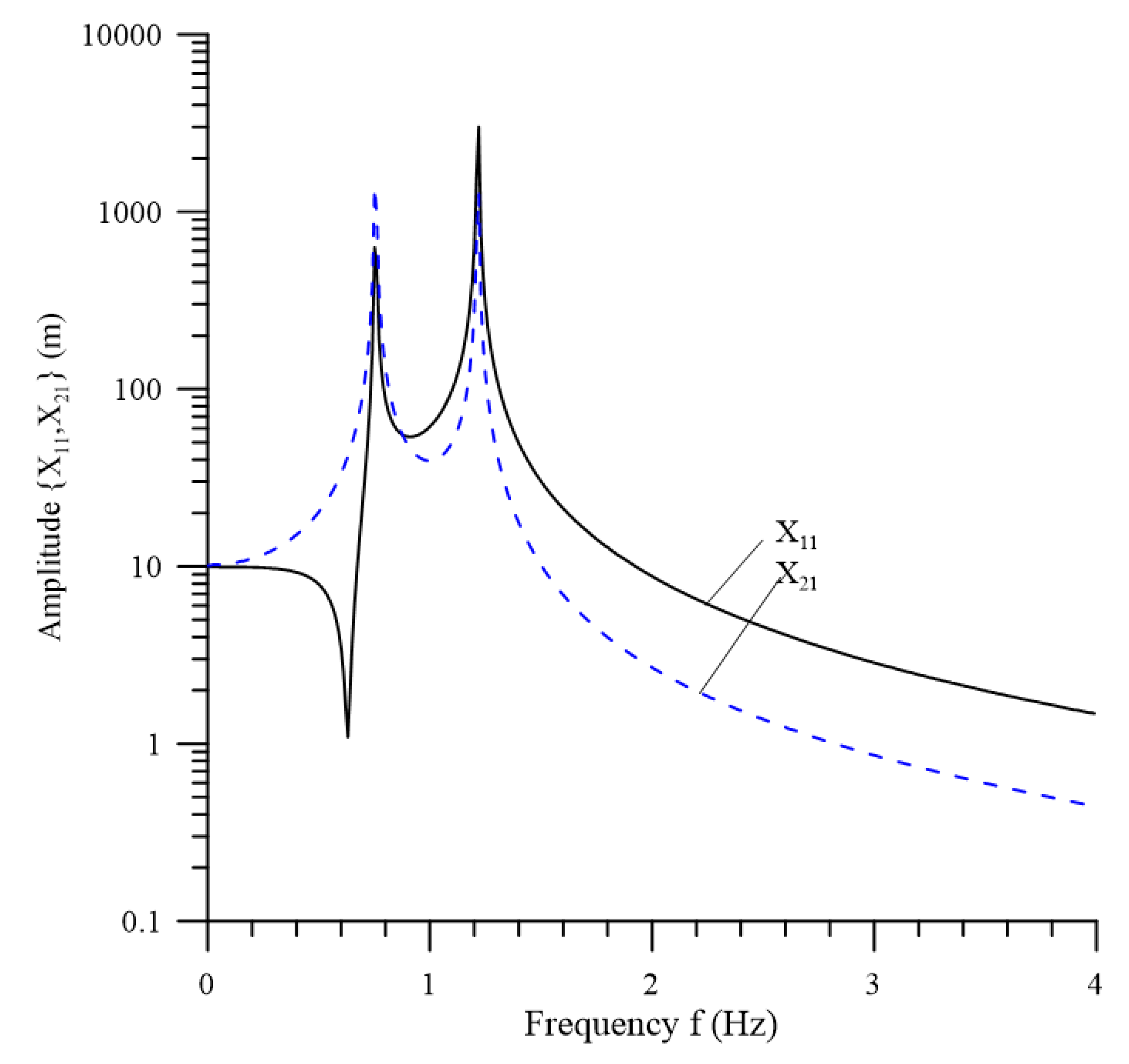
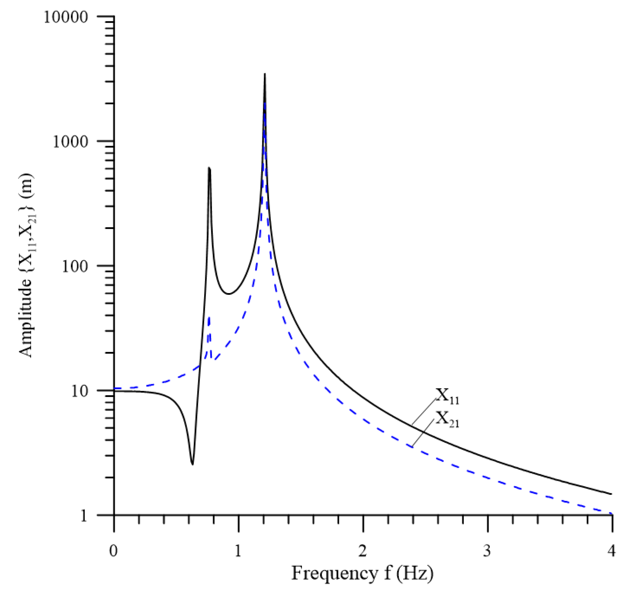
These amplitudes under the condition of { T T u r = 40   tons ,   A 1 = 29.9   m 2 , A 2 = 80   m 2 } at various wave frequencies are shown in Figure 4, where the dynamic motions of the turbine and floater change with the wave frequency. A lower wave frequency causes a lager vertical displacement of the turbine and floater, and the excitation of the floater is larger than that of the turbine. The vertical vibrations have two peaks at the natural frequencies {0.751 Hz, 1.22 Hz}, which are almost the same for the turbine and floater. This is attributed to the resonance vertical motion. Figure 5 shows the effect of wave frequency on { X 11 , X 21 } under the condition of { T T u r = 100   tons ,   A 1 = 29.9   m 2 ,   A 2 = 80   m 2 } . The vertical vibrations have two peaks at the natural frequencies {0.761 Hz, 1.21 Hz}. The results in Figure 4 and Figure 5 show that the pretension T T u r has only a slight influence on the resonance condition.
The effects of the hydrodynamic area of the turbine and floater on vertical excitation are shown in Figure 6 and Figure 7, respectively. 
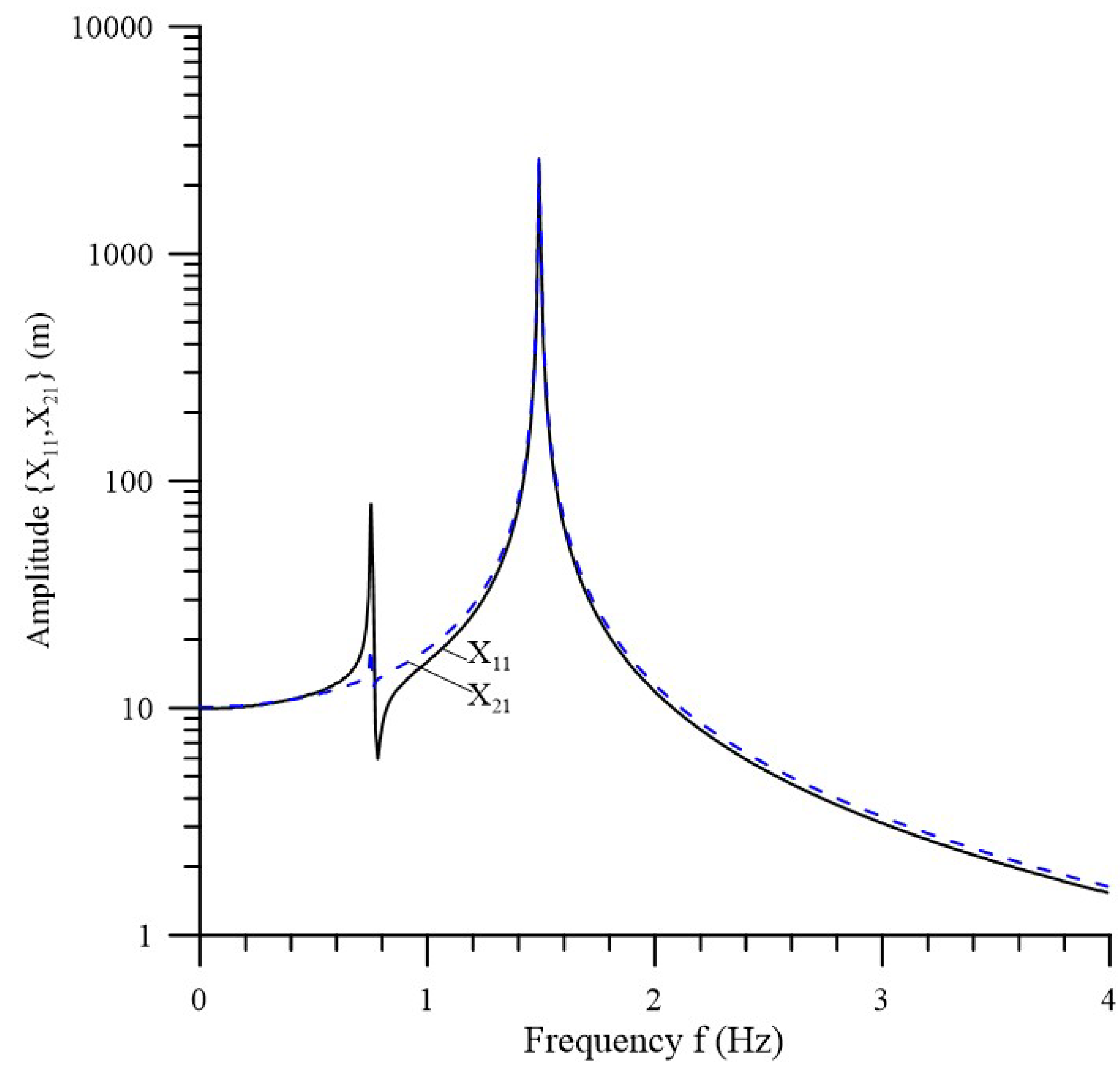
Figure 6 demonstrates the effect of wave frequency on { X 11 , X 21 } at { T T u r = 40   tons ,   A 1 = 29.9   m 2 , A 2 = 120   m 2 }. The two natural frequencies at the resonance are {0.751 Hz, 1.49 Hz}. Compared to 
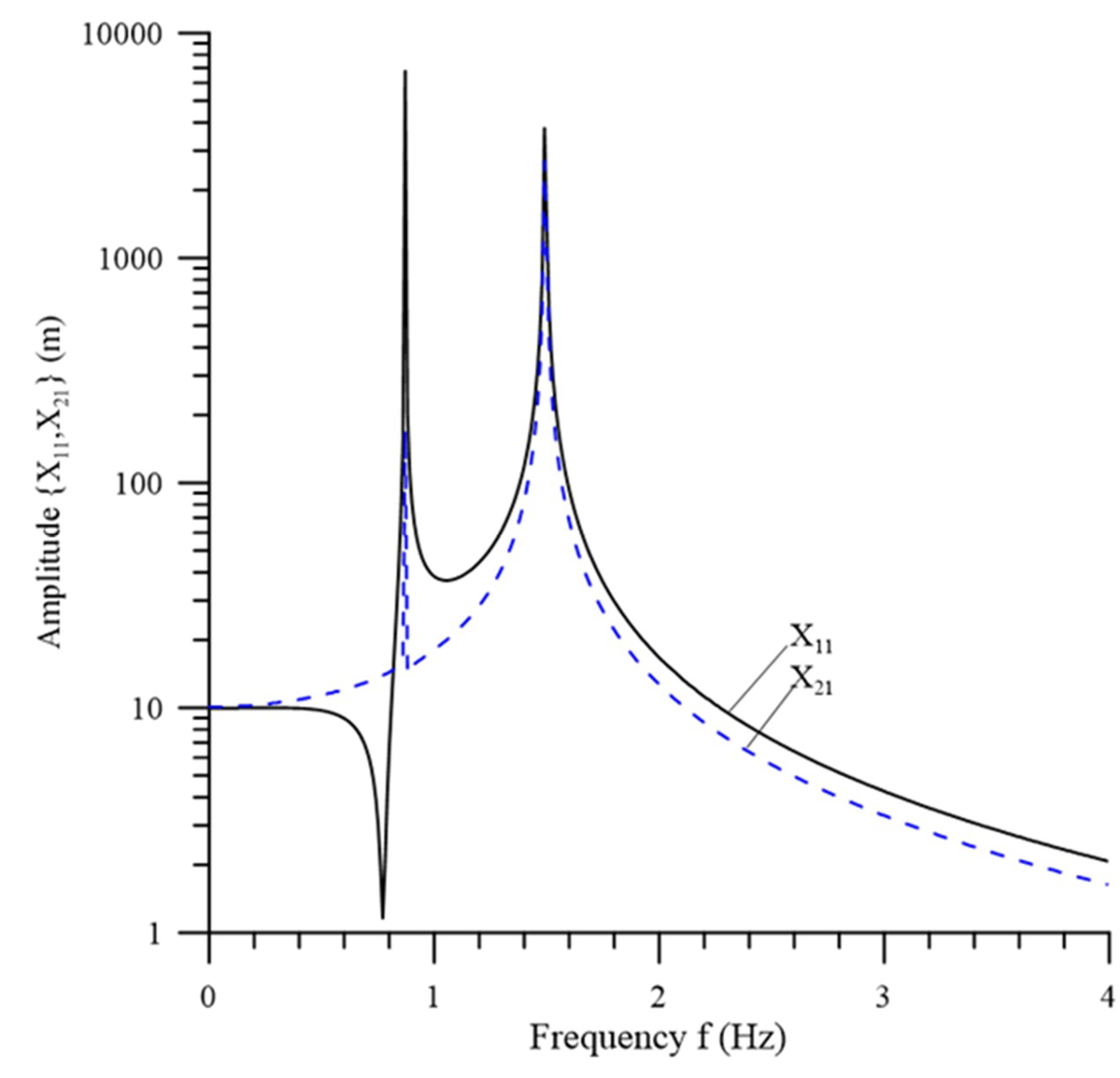
Figure 4, this figure shows that the turbine area has a substantial effect on the second natural frequency. However, the effect on the first natural frequency is negligible. The effect of the wave frequency on { X 11 , X 21 } at { T T u r = 40   tons ,   A 1 = 40   m 2 ,   A 2 = 80   m 2 } is shown in Figure 7. The two natural frequencies are {0.871 Hz, 1.49 Hz}, which differ from the results shown in Figure 4. The resonance effect occurs at higher wave frequencies, which shows that the floater hydrodynamic area has a more substantial influence on the two natural frequencies. We can thus conclude that the larger the floater and turbine areas are, the higher the natural frequencies are. Thus, the effect of the floater area is more significantly greater than that of the turbine area.
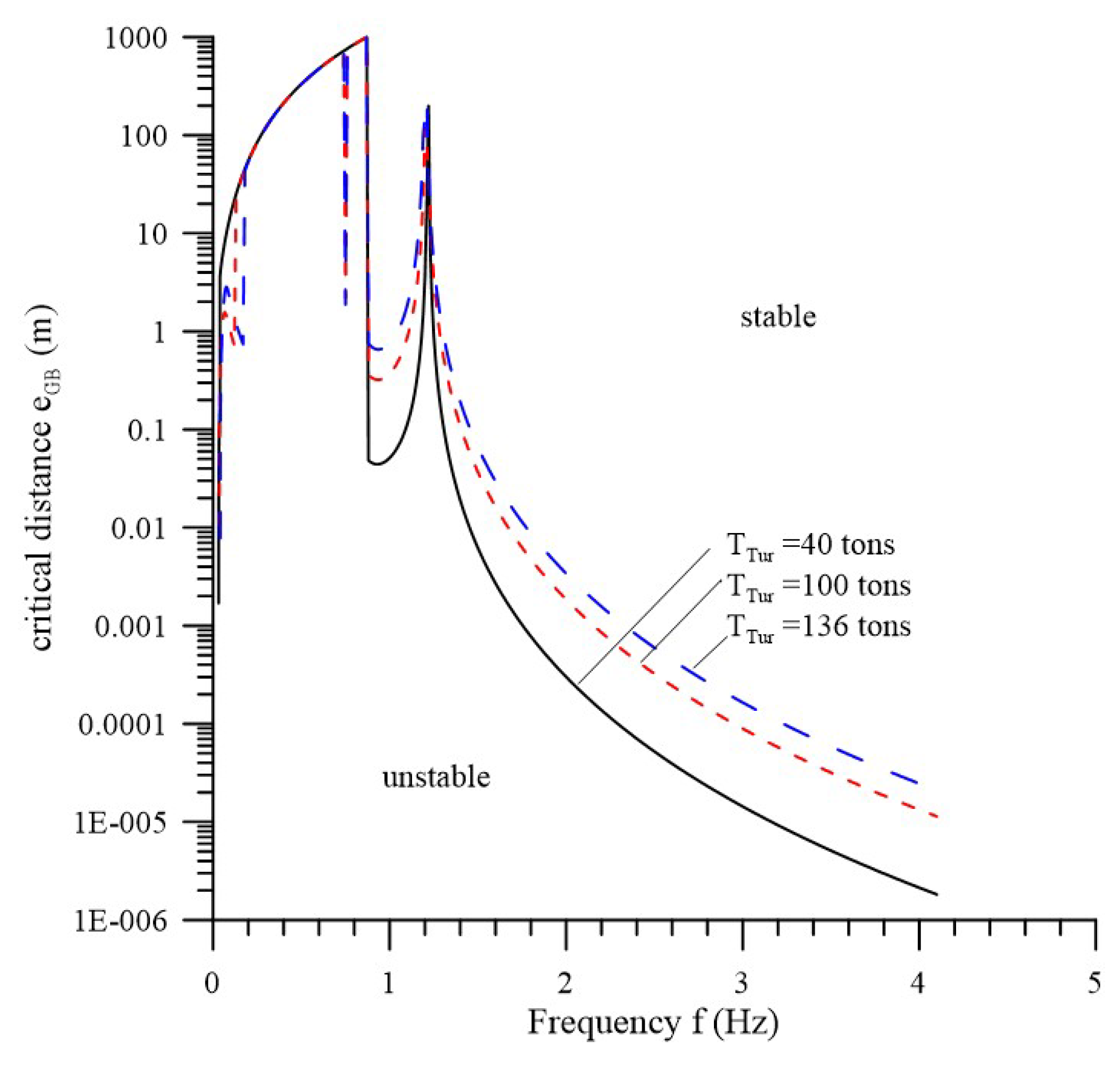
It is well known that when dynamic stability is being considered, a larger- eGB between the gravity and buoyance centers is preferred. The critical distance e G B about the instability of pitching motion is investigated here. 
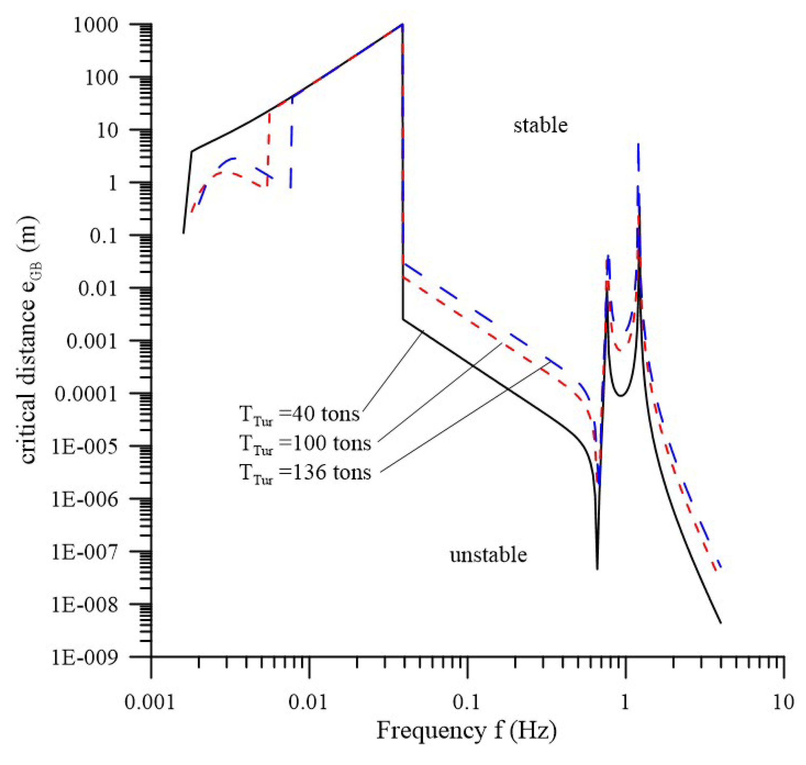
Figure 8 shows the variation in the critical distance e G B with the wave frequencies under three drag forces T T u r at the moment of inertial I = 8.33 × 10 8 ( k g m 2 ) . For the wave frequency over 0.03 Hz, the larger the drag force T T u r , the longer the critical distance e G B , c r i t i c a l . In other word, for the larger the drag force T T u r the longer distance is required for the dynamic stability. Moreover, for a wave frequency over 0.03 Hz, the critical distance, e G B , is less than one, except at a frequency of 1.9 Hz. Thus, if e G B is larger than 1 m, the instability will not occur at a wave frequency above 0.03 Hz. However, for a wave frequency under 0.03 Hz, e G B is larger than 2 m, and thus the ocean current system will be unstable. According to Figure 9, at I = 1.67 × 10 6 ( k g m 2 ) , for the wave frequency under 1 Hz, the critical distance e G B , c r i t i c a l is larger than 2 m and the entire system cannot maintain dynamic stability. It is concluded from Figure 8 and Figure 9 that the larger the moment of inertial I, the better the stability of system.

5. Conclusions

In this study, a mathematical model for a system comprising a turbine, buoyance platform, traction rope, and mooring foundation was developed. A theoretical solution of the dynamic stability analyses of the system is proposed. Based on the presented Formula (21) one can easily tune the natural frequencies of the system away from the wave frequency to avoid the instability of vertical motion. In addition, the critical distance e G B , c r i t i c a l of pitching stability is investigated. Several trends about the stability due to wave excitation are obtained as follows:
(1)
The effect of the pretension T T u r of rope on the natural frequencies of vertical motion is negligible.
(2)
The larger the areas of the floater and turbine, the higher the natural frequencies of vertical motion.
(3)
The larger the moment of inertial I, the better the stability of system.
In subsequent work the influences of nonlinear wave and current interaction will be investigated.

Author Contributions

Conceptualization, S.-M.L., Y.-Y.C., H.-C.H. and M.-S.L.; methodology, H.-C.H., S.-M.L. and Y.-Y.C.; software, H.-C.H. and M.-S.L.; validation, S.-M.L.; formal analysis, H.-C.H., S.-M.L.; investigation, H.-C.H.; resources, H.-C.H.; data curation, S.-M.L. and M.-S.L.; writing—original draft preparation, H.-C.H., S.-M.L. and M.-S.L.; writing—review and editing, H.-C.H.; visualization, S.-M.L.; supervision, Y.-Y.C.; project administration, H.-C.H.; funding acquisition, H.-C.H. All authors have read and agreed to the published version of the manuscript.

Funding

This research was funded bythe Ministry of Science and Technology of Taiwan, R. O. C., grant number MOST 107-2221-E-110-077-MY3.

Acknowledgments

The authors would like to thank the referees for their helpful comments and suggestions. The support of the Ministry of Science and Technology of Taiwan, R. O. C., is gratefully acknowledged (MOST106- 3113-E-110-001-CC2, MOST107- 2221-E-110-077-MY3).

Conflicts of Interest

The authors declare no conflict of interest.

Nomenclature

Across-sectional area
CDdrag coefficient
e D distance between the centers of gravity and drag force
e G B distance between the centers of gravity and buoyance
H0wave height
g gravity acceleration
kwave number
L1distance between the carrier and foundation
L2distance between the carrier and turbine
M1, M2masses of carrier and turbine, respectively
TTurbinetension force of cable between the carrier and turbine
Twiretension force of cable between the carrier and anchor
Ttime variable
Vocean current velocity
X0depth of bed
X1, X2vertical displacements of the carrier and turbine, respectively
Y1, Y2horizontal displacements of the carrier and turbine, respectively
lradius of rotation of turbine about the z-axis
ρdensity of water
Ωwave angular frequency
Φphase due to the delay of propagation from the carrier to the turbine, k L 2
ϕ, θangles of wires at the carrier
ψpitch angle of the turbine
Subscript:
1, 2the carrier and turbine, respectively

References

  1. Lago, L.I.; Ponta, F.L.; Chen, L. Advances and trends in hydrokinetic turbine systems. Energy Sustain. Dev. 2010, 14, 287–296. [Google Scholar] [CrossRef]
  2. Barbarelli, S.; Amelio, M.; Castiglione, T.; Florio, G.; Scornaienchi, N.M.; Cutrupi, A.; Zupone, G.L. Analysis of the equilibrium conditions of a double rotor turbine prototype designed for the exploitation of the tidal currents. Energy Convers. Manag. 2014, 87, 1124–1133. [Google Scholar] [CrossRef]
  3. Barbarelli, S.; Castiglione, T.; Florio, G.; Scornaienchi, N.M.; Zupone, G.L. Design and numerical analysis of a double rotor turbine prototype operating in tidal currents. Energy Procedia 2016, 101, 1199–1206. [Google Scholar] [CrossRef]
  4. Chen, D.; Nagata, S.; Imai, Y. Modelling Wave-Induced Motions of a Floating WEC with Mooring Lines Using the SPH Method. In Proceedings of the 3rd Asian Wave and Tidal Energy Conference, Singapore, 24–28 October 2016. [Google Scholar]
  5. Yang, Y.J.; Jan, S.; Chang, M.-H.; Wang, J.; Mensah, V.; Kuo, T.-H.; Tsai, C.-J.; Lee, C.-Y.; Andres, M.; Centurioni, L.R.; et al. Mean structure and fluctuations of the Kuroshio East of Taiwan from in situ and remote observations. Oceanography 2015, 28, 74–83. [Google Scholar] [CrossRef]
  6. Chen, L.; Lam, W.H. A review of survivability and remedial actions of tidal current turbines. Renew. Sustain. Energy Rev. 2015, 43, 891–900. [Google Scholar] [CrossRef] [Green Version]
  7. Zhou, Z.; Benbouzid, M.; Charpentier, J.F.; Scuiller, F.; Tang, T. Developments in large marine current turbine technologies—A review. Renew. Sustain. Energy Rev. 2017, 71, 852–858. [Google Scholar] [CrossRef]
  8. Chen, Y.Y.; Hsu, H.C.; Bai, C.Y.; Yang, Y.; Lee, C.W.; Cheng, H.K.; Shyue, S.W.; Li, M.S.; Hsu, C.J. Evaluation of Test Platform in the Open Sea and Mounting Test of KW Kuroshio Power-Generating Pilot Facilities. In Proceedings of the 2016 Taiwan Wind Energy Conference, Keelung, Taiwan, 2016. (In Chinese). [Google Scholar]
  9. Coiro, D.P.; Marco, A.D.; Nicolosi, F.; Melone, S.; Montella, F. Dynamic behaviour of the patented kobold tidal current turbine: Numerical and experimental aspects. Acta Polytech. 2005, 45, 77–84. [Google Scholar]
  10. Coiro, D.P.; Maisto, U.; Scherillo, F.; Melone, S.; Grasso, F. Horizontal Axis Tidal Current Turbine: Numerical and Experimental Investigations. In Proceedings of the Owemes, Civitavecchia, Italy, 20–22 April 2006. [Google Scholar]
  11. Shiono, M.; Suzuki, K.; Kiho, S. Output Characteristics of Darrieus Water Turbine with Helical Blades for Tidal Current Generations. In Proceedings of the 12th International Offshore and Polar Engineering Conference, Kitakyushu, Japan, 26–31 May 2002. [Google Scholar]
  12. Cribbs, A.R. Model Analysis of a Mooring System for an Ocean Current Turbine Testing Platform. Master’s Thesis, Florida Atlantic University, Boca Raton, FL, USA, December 2010. [Google Scholar]
  13. Benelghali, S.; Benbouzid, M.; Charpentier, J.F. Generator systems for marine current turbine applications: A comparative study. IEEE J. Ocean. Eng. 2012, 37, 554–563. [Google Scholar] [CrossRef] [Green Version]
  14. Bowie, A.E.D. Flexible Moorings for Tidal Current Turbines. Master’s Thesis, University of Strathclyde, Glasgow, Scotland, 2012. [Google Scholar]
  15. Li, Y. On the definition of the power coefficient of tidal current turbines and efficiency of tidal current turbine farms. Renew. Energ. 2014, 68, 868–875. [Google Scholar] [CrossRef]
  16. Nautricity. Green Energy: Powered by the Sea, Harnessed by Nautricity. 2012. Available online: http://www.nautricity.com/ (accessed on 3 July 2012).
  17. Muliawan, M.J.; Gao, Z.; Moan, T. Application of the contour line method for estimating extreme responses in the mooring lines of a two-body floating wave energy converter. J. Offshore Mech. Arct. Eng. 2013, 135, 031301. [Google Scholar] [CrossRef]
  18. Angelelli, E.; Zanuttigh, B.; Martinelli, L.; Ferri, F. Physical and Numerical Modelling of Mooring Forces and Displacements of a Wave Activated Body Energy Converter. In Proceedings of the ASME 2014 33rd International Conference on Ocean, Offshore and Arctic Engineering, San Francisco, CA, USA, 8–13 June 2014; p. V09AT09A044. [Google Scholar]
  19. Davidson, J.; Ringwood, J.V. Mathematical modelling of mooring systems for wave energy converters—A review. Energies 2017, 10, 666. [Google Scholar] [CrossRef] [Green Version]
  20. Swedish Marine Energy Developer Minesto. Available online: https://www.offshore-energy.biz/the-launch-of-the-worlds-first-subsea-tidal-kite-video/ (accessed on 27 December 2018).
  21. IHI and NEDO. The Demonstration Experiment of the IHI Ocean Current Turbine Located off the Coast of Kuchinoshima Island, Kagoshima Prefecture. IHI Eng. Rev. 2019, 52. [Google Scholar]
Figure 1. Current turbine system composed of turbine (A) (a: Generator; b: Float; c: Structure; d: Translational blade; e: Balanced weight; f: Cable; the current energy transferred by the blade to generator through the high-pressure oil); buoyance platform (B); traction rope (UHMWPE) (C); and anchor (D).
Jmse 08 00687 g001
Figure 2. Concentrated mass model of the ocean current turbine system subjected to wave currents.
Jmse 08 00687 g002
Figure 3. Coordinate and force distribution of the system.
Jmse 08 00687 g003
Figure 4. Effect of the wave frequency f on the amplitudes { X 11 , X 21 } of vertical vibration. ( A 1 = 29.9   m 2 ,   A 2 = 80   m 2 , M 1 = 13.26   tons , M 2 = 100   tons , L 1 = 2780   m , L 2 = 50   m , X 0 = 850   m , H 0 = 10   m , T T u r = 40   tons ).
Jmse 08 00687 g004
Figure 5. Effect of wave frequency f on { X 11 , X 21 } . ( T T u r = 100   tons ; other parameters are the same as those in Figure 4).
Jmse 08 00687 g005
Figure 6. Effect of wave frequency f on { X 11 , X 21 } . ( A 2 = 120   m 2 ; other parameters are the same as those in Figure 4).
Jmse 08 00687 g006
Figure 7. Effect of the wave frequency f on { X 11 , X 21 } . ( A 1 = 40   m 2 ; other parameters are the same as those in Figure 4).
Jmse 08 00687 g007
Figure 8. Effect of the wave frequency f and drag force T T u r on the critical distance between the centers of gravity and buoyance for resonance. ( C D = 1.0 , V = 1   m / s , e D = 1   m , = 1   m , I = 8.33 × 10 8 ( k g m 2 ) ; other parameters are the same as those in Figure 4).
Jmse 08 00687 g008
Figure 9. Effect of wave frequency f and drag force T T u r on the critical distance between the centers of gravity and buoyance for resonance. ( I = 1.67 × 10 6 ( k g m 2 ) ; other parameters are the same as those in Figure 8).
Jmse 08 00687 g009

