Abstract
A disc-type underwater glider (DTUG) has a highly symmetrical shape and is characterized by omnidirectional characteristics and high maneuverability in small bodies of water. To further explore the disc shape’s advantages and characteristics in steering motion, DTUG motion was simulated by Matlab/Simulink. Based on the structural characteristics of DTUG, the motion control equations were established. The simulation of DTUG’s steering motion is carried out and compared with a previous DTUG (LUNA). The sensitivity analysis and Lyapunov stability analysis were also conducted. The results showed that the in situ steering motion can be realized by controlling the position of the center of gravity (CG) of DTUG without moving vertically, which facilitates rapid adjustment of the yaw angle and flexible movement in small bodies of water. The in situ steering motion was significantly affected by the control parameters. The parameter that had the greatest effect on it can be obtained through sensitivity analysis, which can guide DTUG to better adjust the yaw angle under different conditions. The stability analysis showed that the DTUG can remain stable within the range of the control parameter.
1. Introduction
Underwater glider (UG) is driven by the net buoyancy, and its attitude angle is controlled by the attitude adjustment system. UG does not require buoyancy and attitude control systems to work during steady-state gliding. It has the advantageous characteristics, such as low energy consumption and long endurance, as well as long-range monitoring [1] in ocean environment detection and monitoring. Since the UG concept was first demonstrated by Stommel [2], various gliders have been developed by the countries around the world, of which the United States is leading the pack. The three gliders, “Slocum” [3], “Seaglider” [4], and “Spray” [5], are representative of them and have been industrialized and widely applied in ocean observation [6]. To meet the different needs of marine missions, a variety of UGs have emerged. For example, the “Z-Ray” [7], with heavy payload capability, the “DeepExplorer” and “UltraDeepExplorer” [8], with operating depths of 2400 m and 5000 m, respectively, the “Deepglider” [9], with an operating depth of 6000 m, and the “Sea-Explorer” [10], with a high gliding velocity, have been developed. The disc-type underwater gliders (DTUGs), named “LUNA” [11] and “BOOMRANG” [12], with flexible maneuverability have been proposed and tested, as well. The research in this paper mainly focused on the self-designed DTUG, and the purpose was to explore the advantages and characteristics of the DTUG’s disc shape in motion to expand the application area of UGs.
The concept of the disc-shape design introduced into the UG was first proposed by Nakamura et al., and two different sizes of DTUGs were successfully developed: “LUNA” [11] and “BOOMRANG” [12]. These DTUGs do not have any appendage, such as rudders and propellers. They could glide in any direction around the disc by adjusting the attitude adjustment system and buoyancy control system. According to their published research, the feasibility of the disc-shape design on the UG was proven by the prototype test. Besides, the hydrodynamic model of DTU was established, and the motion in the vertical plane and steering motion was simulated in Matlab and Simulink. It can be seen from the results that the turning radius of the DTUG steering motion is smaller than that of the torpedo-type underwater glider (TTUG). In practical applications, the DTUG is more suitable for virtual-mooring tasks than a conventional mooring system, which solves the problem that the latter can observe only discrete data in perpendicular space and requires great manpower and expense on the system construction [11]. Also, the oceanographic observations were made in the west sea area of Japan’s Kami-Goto islands and the East China Sea by using the “BOOMRANG” [13,14]. As a new type of UG, DTUG’s unique shape design will be bound to affect the hydrodynamic characteristics of the glider, thus bringing some different motion characteristics to DTUG, such as omnidirectional motion characteristics [15], bottom sitting performance [16], and vertical motion characteristics with zero pitch angle [17]. In [18,19], the overall design and the attitude predictive control of a disc-type underwater robot with water-jet propeller were implemented. The prototype experiments showed that the disc-type underwater robot can maintain stable navigation only when the water-jet propeller is activated frequently. The analysis method of the DTUG’s hull-shape design was established in [20]. The influence of the diversion edge and the height of the disc shape on the hydrodynamic and kinetic performance of DTUG was further analyzed. It was found that the horizontal gliding distance corresponding to the unit height was increased by the diversion edge, while the sliding velocity in the horizontal direction was decreased. Decrease of the height will increase the horizontal sliding velocity but does not influence the horizontal gliding distance. The three-dimensional simulation of a DTUG was conducted in [21], and the feasibility of the disc shape was verified. The results also showed that the linear steady motion of the DTUG was the same as the TTUG and did not cause unnecessary rotation during the zigzag downward and upward gliding. A nonlinear dynamic model for the DTUG was developed in [15], and the feasibility of this dynamic model was validated. The DTUG showed good maneuverability through the simulations of the typical motions. The cooperative diving problem of homogenous under-actuated DTUG subject to model uncertainties, input constraints, and external disturbances was studied in [22], and a modular back-stepping design method was used to design a robust adaptive cooperative diving controller for each glider. The results showed the effectiveness of this method in cooperative diving of DTUG in the vertical plane. The motion planning of the multi-UG system was studied in [23]. A method of constructing a stable glider formation of arbitrary shape was proposed, combining the artificial potential field method and the virtual pilot method. This method of formation was attempted to be applied to the DTUG. The vertical motion with zero pitch angle for the DTUG was proposed in [17], based on the advantages of the disc shape on vertical motion. The motion characteristics of this motion mode, as well as the typical motions, were fully analyzed to reveal the difference between the DTUG and a hybrid-driven underwater glider (HUG) [24]. The results showed that the DTUG could achieve the vertical motion with zero pitch angle in the vertical plane to easily collect the various ocean environment parameters at different depths in the designated area.
In studying the conventional steering and spiral motion of the TTUG and DTUG, Bhatta and Leonard [25] attempted to find numerical solutions for the equations characterizing the spiral motion of UGs, and some simulation results were presented in [26]. The theoretical effort was extended to investigate the steering performance of the Zhejiang University (ZJU) glider varying with vertical rudder configuration [27]. By analyzing the steady spiral motion of UGs, a recursive algorithm with fast convergence was obtained, and the simulation results had a good agreement with field tests where the glider produced a spiral motion against the strong current [28]. The recursive algorithm was also used to analyze the steering and spiral motion in [29,30]. An 8 degrees-of-freedom dynamic model was derived for a UG operating in an unsteady, nonuniform flow in [31]. Note that the rigid glider body had 6 degrees of freedom in translation and rotation in three-dimensional space, the translational motion of the attitude adjustment weight had 1 degree of freedom, and the swing of the tail rudder had 1 degree of freedom. A nonlinear simulation model was established in [32] based on Kirchoff’s equation. The simulation results, compared with the experimental results of the steering motion of HUST-2 glider, agreed well with each other. The three-dimensional unsteady motion of a disc-UG prototype was simulated in [21], and the steering movements during the linear gliding process by the use of multi-body dynamics were further analyzed. The gliding and spiral motion of a fly-wing, dish-shaped UG were analyzed in [33], and the simulation results proved its excellent hydrodynamic performance and gliding economy. The simulation method of the steady spiral motion of UGs was established in [34], and the variation law of the temporal and spatial scales with control parameters was quantitatively researched. The characteristics of the DTUG’s spiral motion were studied in [24,35], and the feasibility of micro-torque control of the DTUG’s steering motion was further discussed. The results showed that the micro-torque can not only control the DTUG’s rotation but also eliminate the yaw angle generated by external disturbances.
Although the UG can glide in the direction contained in its body, fixed horizontal xy plane (o-xyz) was used to describe the body frame in this paper, as described in Section 2.1. It can only glide along the ox-axis by linear motion, which is the direction of displacement of linear movable mass. If the UG is to glide in other directions in the xy plane, it has to use the steering motion mode, which needs to be done in the wide area of the open ocean. As for DTUG, the highly symmetrical shape allows the DTUG to glide in all directions along the xy plane by adjusting the CG’s position and driven by the net buoyancy. The hydrodynamic characteristics and motion characteristics are the same in all directions, which is called the omnidirectional motion characteristics. However, the existing research on DTUGs is based on the research methods of TTUGs to analyze the motion performance and characteristics of DTUGs. Most of the research stayed in the vertical plane motion and steering motion of DTUG. Although the results showed that the DTUG’s part of the motion performance was better than that of the TTUG, this was not significantly different from the TTUG’s motion mode. Some researchers have realized that the disc shape will have a huge impact on the UG’s motion, and have done relevant research, but more advantages of the disc shape are stilled waiting to be explored. This paper proposes the in situ steering motion mode to further develop the disc shape advantages in DTUG steering motion. The in situ steering motion means that the DTUG only adjusts the position of the CG of the glider through the attitude adjustment system to achieve the adjustment of the yaw angle, while keeping the net buoyancy at zero. Therefore, the linear displacements of the DTUG in space is zero during the process of the in situ steering motion. In summary, it can be seen that the method used to study the motion performance of the DTUG is usually the same as the method used when studying the motion performance of the TTUG. The methods are mainly the simulation analysis and experimental research on the linear steady motion and spiral steady motion. To further study the advantages of the disc shape, this paper proposes the in situ steering motion mode for the DTUG for the first time and used the motion control equations to simulate the in situ steering motion and compare with those of a TTUG and a former DTUG (LUNA). Additionally, this paper analyzes the sensitivity of the control parameters on the motion performance of the DTUG and the stability of the in situ steering motion for the first time. We hope to reveal the motion characteristics of the in situ steering motion of this new concept underwater glider through in-depth research of its motion performance, sensitivity, and stability. We believe that this research is of positive significance for expanding the diversified shape design of UGs.
The remainder of this paper is structured as follows. Section 2 introduces the DTUG for modeling, and the mathematical model with control inputs was derived based on the momentum theorem and the moment of momentum theorem. In Section 3, the in situ steering motion of the DTUG is proposed, and its motion performance and characteristics were analyzed using MATLAB/Simulink. The results were then compared with a TTUG, and the sensitivity analysis and stability analysis of the in situ steering motion was performed. The discussions are provided in Section 4. Finally, Section 5 concludes the study.
2. Modeling of the DTUG
2.1. Frames of Reference
DTUG is modeled as a rigid body with four movable masses, and its full-wing body is shown in Figure 1. Furthermore, the total stationary mass m is the sum of the four items: m = mh + mw + mp + mb, where mh is uniformly distributed over the fuselage of the DTUG, mw may be offset from the center of buoyancy (CB), mp is the sum of four movable point masses, mp = mp1 + mp2 + mp3 + mp4, and mb is the variable ballast point mass for buoyancy adjustment and considered as a variable mass with a fixed position in this paper. The distribution of the above-mentioned various masses in the DTUG is shown in Figure 2. The mass of the fluid displaced by the DTUG is defined as mv and can be computed by mv = ρV, in which V is the total displacement volume of the glider and ρ is the fluid density. Define the glider’s net buoyancy as m0 (m0 = m − mv), so that the glider will sink when m0 > 0 and rise when m0 < 0. When m0 = 0, the glider is in a neutral buoyancy state.
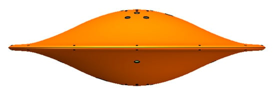
Figure 1.
Full-wing body of a disc-type underwater glider (DTUG).
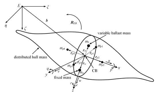
Figure 2.
DTUG internal masses’ and frames’ assignment.
As shown in Figure 2, E-ξηζ is defined to represent the inertial frame, where E is the origin of the inertial frame, Eξ, Eη, Eζ are the three axes of the inertial frame. The inertial frame E-ξηζ and body frame o-xyz are used to describe the six dimensions-of-freedom motion of the DTUG. The inertial frame E-ξηζ is fixed to a point in the inertial space or on the sea surface. The ζ-axis lies in the direction of gravity and is positive downwards; the ξ-axis and η-axis lie in the horizontal plane, perpendicular to gravity. The body frame is fixed to the DTUG, and its origin coincides with the CB. The z-axis points in the direction orthogonal to the symmetry plane between the upper and lower parts of the DTUG, and the x-axis and y-axis lie in this symmetry plane. The linear velocity of the DTUG along the x, y and the z-axis is defined as u, v, and w, respectively. The angular velocity along the x, y and the z-axis is defined as p, q, and r. These velocities are all described in the body frame, as shown in Figure 2. The parameters of the DTUG shown in Figure 2 are listed in Table 1.

Table 1.
Main parameters of the DTUG.
Let rotation matrix REB be the DTUG orientation from the body frame to the inertial frame, and the rotation is parameterized by the Euler angles Λ = (φ, θ, ψ)T: The roll angle φ, pitch angle θ, and yaw angle ψ. Note that this paper uses Euler angles to describe the attitude of DTUG. However, DTUG cannot reach a pitch angle θ of 90 degrees. DTUG usually glides with a small pitch angle θ to expect the maximum horizontal displacement when the vertical displacement is the same to increase the DTUG’s cruising range. Besides, the pitch angle θ is mainly affected by the displacement of the movable mass. Because the track length of the movable mass is limited (as shown in Figure 3), the DTUG cannot reach the pitch angle of 90 degrees, even at the maximum displacement. Although any direction can be used as the forward direction, considering that DTUG is the full-wing shape and has omnidirectional motion characteristics, to build the DTUG’s motion control equations, the roll φ is defined as positive when the right wing of DTUG is down (Eη direction), concerning the inertial frame in Figure 1. Pitch θ is positive when front wing is up (Eξ direction) and yaw ψ is positive clockwise when viewed from above. Using the simplified notations c·= cos(·) and s·= sin(·) [36], REB can be expressed as follows:
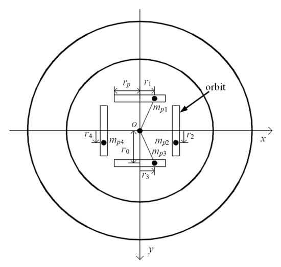
Figure 3.
The attitude adjustment system of the DTUG.
Use vector b = (ξ, η, ζ)T to describe the position of the DTUG from the origin of the inertial frame to the origin of the body frame. Let vector v = (u, v, w)T and vector ω = (p, q, r)T be the linear velocity and angular velocity vectors in the body frame. Define operator ‘ˆ’ as the skew-symmetric matrix constructed from a vector. Thus, for the vector ω, have the form of
Then, the kinematics of the DTUG are given by
The transformation matrix RΛB is defined to describe the relationship between the Euler angles in the inertial frame and the angular velocity in the body frame [37], with the following form:
2.2. Motion Control Equations
The dynamic equations of the DTUG can be established based on the momentum theorem and the moment of momentum theorem. The variables involved in the dynamic equations and following equations and their meanings are listed in Table 2.

Table 2.
The meanings of the variables mentioned in the dynamic equations.
The external force FS and moment TS are composed of static and hydrodynamic forces and moments, respectively, where static forces include gravity and buoyancy.
and can be written as
Thus, the static force P and moment TP, concerning the body frame, can be obtained by coordinate transformation:
where rCG and rCB have the vector forms, as shown below:
where the meanings of xG, yG, zG, xB, yB, and zB are shown in Table 2. Thus, Equation (10) can be expanded into the vector form, as shown below:
The difference in the attitude adjustment system between DTUG and TTUG [3,4,5] is the number and layout of the movable masses. In principle, the attitude adjustment of the DTUG can still be achieved by changing the position of CG through adjusting moveable masses. As shown in Figure 3, the attitude adjustment system of the DTUG is mainly composed of four moveable masses and four rectangularly arranged orbits. These four moveable masses are driven by four stepping motors and move along their own respective orbits. The mpi is represented as the movable mass, as mentioned in Section 2.1, and rpi, with respect to the body frame, can be used to describe the position of the mass block mpi. Let ri describe the displacement of the mass block mpi, rp represent the half-length of the orbit (), and r0 describe the movable blocks (ox-direction or oy-direction) so that rpi can be written as:
Note that the values of i in this paragraph are 1, 2, 3, and 4.
The position vector rCG is determined by these four mass blocks and can be written as:
where the meanings of xrb, yrb, and zrb are listed in Table 2. The dynamic equations of the DTUG in the inertial frame are shown in Equation (6) and can be converted in the body frame:
Then, these equations can be expressed as the matrix form and as shown below:
where the form of the hydrodynamic model is as follows:
Note the hydrodynamic model used in (16) (PH and TH) is simplified from a general model established, based on the submarine hydrodynamic model. Refer to the reference [11] for the simplification strategy of the DTUG hydrodynamic model. This paper mainly simplified the general model based on the following two points: (1) The shape of DTUG is symmetrical from left to right, front to back, and from top to bottom, and (2) the velocity of DTUG is low, and most of the time is making steady-state glide motion. Thus, the influence of the surrounding water flow on the complex turbulence effect can be ignored in this case. The specific derivation process can refer to an author’s previous research content [38]. Combined with the above formula derivation, the motion control equations of the DTUG can be obtained, and its matrix form is as follows:
where
where Ixx, Iyy, and Izz are the inertia moments; A11, A22, and A33 are the added masses; and A44, A55, and A66 are the added moments of inertia. The Aii (i = 1, 2, …, 6) and hydrodynamic coefficients of the DTUG were obtained from computational fluid dynamic (CFD) numerical simulation (the detailed calculation method is shown in Section 2.3 and the calculation process refers to [15]). These dimensionless coefficients are listed in Table 3.
X = −(m + A33)qw +(m + A22)rv + (mrbxrb + mp1r1 + mp3r3)(q2 + r2) − (mrbyrb + mp2r2 + mp4r4)pq − mrbzrbpr − (m − ρV)gsθ + Xuuu2 + Xwww2,
Y = −(m + A11)ru + (m + A33)pw + (mrbyrb + mp2r2 + mp4r4)(p2 + r2) − (mrbxrb + mp1r1 + mp3r3)pq − mrbzrbqr − (m − ρV)gsφcθ + Yvv + Yv|v|v|v|,
Z = −(m + A22)pv + (m + A11)qu + mrbzrb (p2 + q2) − (mrbxrb + mp1r1 + mp3r3)pr − (mrbyrb + mp2r2 + mp4r4)qr + (m − ρV)gcφcθ + Zww,
K = mrbzrb(ru − pw) − (Izz − Iyy + A55 − A66)qr − (A33 − A22)vw + (mrbyrb + mp2r2 + mp4r4)(qu − pv) − (mrbyrb + mp2r2 + mp4r4 − ρVyB)gcφcθ − (mrbzrb − ρVzB)gsφcθ + Kpp + Kp|p|p|p|,
M = mrbzrb(rv − qw) − (Ixx − Izz + A44 − A66)pr − (A11 − A33)uw + (mrbxrb + mp1r1 + mp3r3)(pv − qu) − (mrbxrb + mp1r1 + mp3r3 −ρVxB)gcφcθ − (mrbzrb − ρVzB)gsθ + Mww + Mq|q|q|q|,
N = (mrbxrb + mp1r1 + mp3r3)(pw − ru) − (Iyy − Ixx − A44 + A55)pq − (A22 − A11)uv + (mrbyrb + mp2r2 + mp4r4)(pw − rv) − (mrbxrb + mp1r1 + mp3r3 − ρVxB)gsφcθ − (mrbyrb + mp2r2 + mp4r4 − ρVyB)gsθ + Nrr + Nr|r|r|r|,

Table 3.
Dimensionless coefficients of the DTUG.
2.3. Calculation Method of Hydrodynamic Coefficients
A computational fluid dynamics’ software package, the FLUENT that implements the Reynolds-averaged Navier–Stokes equations, were used to compute the hydrodynamic coefficients in this paper. For the DTUG, the low Reynolds turbulence models gave good estimation [37], so the re-normalization group k-ε (RNG k-ε) model, considering the effect of low Reynolds number, was used to simulate the surrounding flow. The GAMBIT software was used to create a mesh for the DTUG, and the fluid volume meshed as two structured grid fields, a coarse mesh field for the fluid field farther away from the glider hull and a refined field confined to the fluid volume close to the hull. The dynamic mesh technology was utilized to simulate the small-amplitude plane motion of the DTUG. The fluid boundary conditions were specified, as follows: (1) The DTUG surface boundary was set as a no-slip wall, (2) the upstream inlet a velocity-inlet boundary, and (3) the downstream outlet satisfied the zero static pressure condition, and the other boundaries were free-slip walls.
Static simulations comprised a numerical resistance simulation and an attack angle change simulation [16]. The x-axis hydrodynamic coefficient Xuu was measured in the numerical resistance simulation, where the average value was calculated by using the inlet velocity between u = 0.5 kn and u = 1 kn when the attack angle α = 0°. The x-axis hydrodynamic coefficient Xww, the z-axis hydrodynamic coefficient Zw, and the hydrodynamic coefficient around the y-axis Mw can be determined through the attack angle test by letting u vary from 0.5 kn to 1 kn when fitting by the least-squares method is carried out using the data between α = −4 and α = 4°.
Dynamic simulations with five kinds of forced oscillation simulations, consisting of forced surging, swaying, heaving, pitching, and yawing simulation, were carried out to estimate the dynamic-hydrodynamic coefficients such as added mass coefficients [28,39]. In these simulations, the inlet velocity between u = 0.5 kn and u = 1 kn and the oscillation frequency between ω = 2 rad/s and ω = 4 rad/s were determined. The average values of the hydrodynamic coefficients were calculated with the results of them. In the forced surging simulation, the added mass A11 and the damping coefficient Xuu can be determined. It was found that Xuu obtained from the static simulations was in a good agreement with the result obtained from the dynamic simulations. Because of the highly symmetrical, full-wing shape of the DTUG, it can be drawn that A11 is equal to A22, which was also proved by the swaying simulation where the damping coefficients Yv and Yv|v| were obtained as well. A33, Zw, and Mw can be determined in the heaving simulation, and the value of Zw and Mw agreed well with that obtained in the static simulations. Furthermore, the value of added moments of inertia A55, the hydrodynamic coefficient around the y-axis Mq and Mq|q| can be calculated through the pitching simulation and added moments of inertia A66, the hydrodynamic coefficient around the z-axis Nr and Nr|r| can be calculated through the yawing simulation. added moments of inertia A44, the hydrodynamic coefficient around the x-axis Kp and Kp|p| can be obtained due to the high symmetry of the DTUG [16].
3. Simulation on the Motion of DTUG
The main parameters of the DTUG studied in this paper are listed in Table 4.

Table 4.
Main parameters of the DTUG.
Let xGmax and yGmax represent the maximum offset of CG of the DTUG in the x-axis direction and y-axis direction, respectively, and xGmax is equal to yGmax. Thus, combined with Equation (14), Figure 3, and Table 4, the following equation can be obtained:
According to this equation and the DTUG’s attitude adjustment system’s design, the range of values of xG and yG was defined as 0 to 0.005 m in the following analysis. The simulation on the motion was carried out using Matlab and Simulink, and the program is shown in Figure 4.
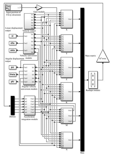
Figure 4.
DTUG motion simulator by Matlab and Simulink.
3.1. Conventional Steering Motion
The spiral motion is one of the typical motions of a UG, and can maintain the UG’s position [40]. As a special-shaped UG, DTUG can also achieve spiral motion by controlling the position of the CG (indirectly adjust the position of the CG by controlling the displacement of the movable masses, as shown in Equation (14)) and net buoyancy. The trajectory is shown in Figure 5. The spiral motion in Figure 5 was achieved by adjusting the movable mass through the attitude adjustment system and the net buoyancy through the buoyancy control system. The control parameters were set as: m0 = 0.4 kg, xG = 0.004 m, yG = 0.002 m. Note that because the movable mass’s displacement is reflected in the change of the CG’s position (refer to Equation (14)), the value of the CG’s position is directly given here. This paper focused on the DTUG’s motion performance changes under the input of different control parameters. Therefore, the control parameters were set to a certain value at the simulation’s initial state without consideration of how the control parameters reach the set value under the controller. Zhou et al. [24] performed a simulation on the spiral motion of the third-generation DTUG. The results of this study showed that the radius of the spiral motion of the DTUG decreased with increasing yG and increased with increasing xG. To distinguish the in situ steering motion, this paper refers to the steering motion under the common control of the buoyancy control system and the attitude adjustment system as the conventional steering motion. The conventional steering motion is similar to the spiral motion, and its motion performance is also affected by the control parameters, including xG, yG, and m0. The biggest difference is that yG remains constant during the spiral motion, while yG varies with time during the conventional steering motion.
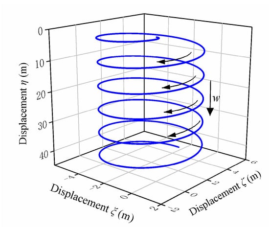
Figure 5.
Spiral motion trajectory of a DTUG.
The control parameters of the DTUG were set as follows: m0 = 0.4 kg, xG = 0.005 m,
Then, the motion control equation was solved in MATLAB, and the conventional steering motion trajectory of DTUG could be obtained, as shown in Figure 6.
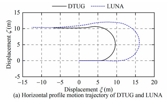
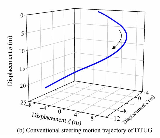
Figure 6.
The trajectory of the conventional steering motion of the DTUG.
Figure 6a,b shows the conventional steering motion trajectory of the DTUG (fifth generation) studied in this paper and the LUNA, respectively. Through the comparison with LUNA, it found that the trajectories of the two gliders were quite similar, and the only difference was that LUNA’s steering motion trajectory was smoother, because the Linear-Quadratic-Integral (LQI) controller controlled the steering motion of LUNA, while the DTUG had not been given a controller. Different controllers adjust the glider’s control parameters through different control strategies so that the glider can achieve the set motion state. The focus of this paper was to study the changes in the steady-state motion of the DTUG after the control parameters were changed, that is, the motion performance prediction (the detailed description is in Section 3.2), so there was not much discussion about how the control parameters change under the controller. From the results in the literature and Figure 6, it can be drawn that DTUG can also perform the spiral motion and conventional steering motion, and the turning radius is smaller than that of the TTUG [28]. As shown in Equation (17), DTUG’s motion equations and LUNA’s motion equations [10] have the same expression on the left side of the equal sign in Equation (17), while the expression on the right side of the equal sign is different. The difference is mainly the number and layout of the movable masses in the attitude adjustment system, which are reflected by the CG’s position in motion equations, as shown in Figure 3 and Equation (14). Thus, the motion equations of DTUG and LUNA are very similar. Figure 6b was obtained by substituting the LUNA’s parameters in [10] into the motion equations proposed in this paper. Since the reference only gives the time evolution curve of the control parameters under the controller’s control and does not give the specific parameters of the controller, there was an error between the control parameters used in this paper and reference when simulating the steering motion of LUNA. Though this error led to the slight difference between LUNA’s motion trajectory in Figure 6b and the motion trajectory of LUNA in [10], the reflected motion characteristics and performance were consistent with the reference. Because the LUNA’s motion trajectory calculated by the motion equations proposed in this paper was consistent with the motion trajectory (validated by experimentation) in [10], the motion equations proposed in this paper are reasonable.
As mentioned above, the DTUG can achieve conventional steering motion, and the biggest difference between DTUG and TTUG is that the DTUG has a smaller turning radius and pitch. In practical applications, the smaller turning radius and pitch allow DTUG to adjust the direction of movement through steering motion in a smaller space or maintain the direction by spiral motion in shallow water, making DTUG more suitable for performing tasks in small bodies of water with limited depth of water.
3.2. In Situ Steering Motion
This section aims to analyze the characteristics and performance of the DTUG’s in situ steering motion affected by the control parameters, which is the motion performance prediction. The motion controller design and motion performance prediction are important and valuable research content when studying the UG’s motion’s dynamic characteristics. The motion performance prediction is the basis of the motion controller design so that the controller can control the glider to complete the motion more accurately. Based on the research content focus and space limitations, this section mainly focuses on the motion performance prediction of the DTUG without a controller.
3.2.1. Motion Description
The linearly movable masses of DTUG can also be used to adjust the pitch angle, which is the same as that of TTUG. The difference is that the TTUG relies on rotatable mass or classical rudders [3] to realize the steering motion, while the DTUG only has four linearly moveable masses, no rotatable mass. Benefiting from the highly symmetric shape, the resistance moment along the z-axis is quite small, and DTUG can start an adjusting yaw angle with a small steering moment. Thus, the linearly movable mass enables the DTUG’s spiral motion by generating an eccentric quantity in the y-axis direction (yG) and the in situ steering motion. The attitude adjustment system and buoyancy control system must cooperate to achieve the yaw angle adjusting of TTUG. During this process, the attitude adjustment system adjusts the pitch angle (linear movable mass) and forward direction of the glider (rotatable mass or the classic rudder). The buoyancy control system provides a driving force for the glider by adjusting the net buoyancy. Therefore, not only the turning radius of the TTUG is large, but also a large vertical space is required, which means that the wide area of the open ocean is necessary for TTUG to complete the steering motion. The in situ steering motion of a DTUG was proposed for the first time in this paper. It is described as that DTUG can be rotated in situ by a small steering moment, due to a small resistance around the z-axis direction, and no net buoyancy is required. Based on the structural characteristic of the DTUG, the steering moment can be generated by adjusting the CG position of the DTUG, thereby achieving the in situ steering motion. The net buoyancy remains at zero during the in situ steering motion; thus, no vertical displacement occurs, which is beneficial for the DTUG to operate in small bodies of water with limited depth. The schematic diagrams of TTUG’s steering motion and DTUG’s in situ steering motion diagrams are shown in Figure 7.
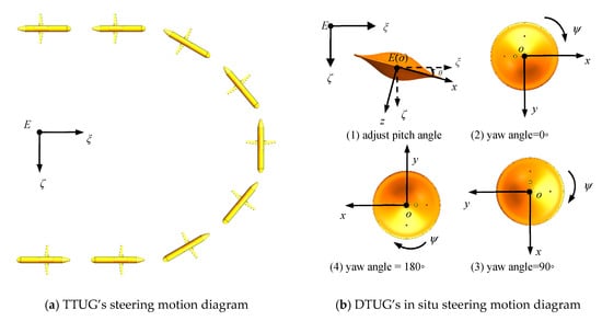
Figure 7.
TTUG (torpedo-type underwater glider) and DTUG steering motion diagram.
Note that Figure 7 mainly describes the change process of the yaw angle and is viewed from above. Although the DTUG has omnidirectional motion characteristics and theoretically any direction can be regarded as the forward direction, to analyze the time evolution of the yaw angle to make it easier to understand, the x-axis is still fixed, directed to the main forward direction of the DTUG. As shown in Figure 7a, when the forward direction of the TTUG changes by 180 degrees, the turning radius of TTUG is large, and there will be a large vertical displacement. It indicates that the TTUG needs horizontal space and vertical space to complete the steering motion. As shown in Figure 7b, there are two steps for DTUG to complete the in situ steering motion: First, set the net buoyancy m0 as zero and adjust the xG to make the DTUG generate a pitching angle θ ((1) in Figure 7b) and second, the attitude adjustment system is controlled to generate a small offset in the y-axis direction (yG), and the offset is again adjusted to zero after a period, whereby the DTUG can rotate around the z-axis ((2), (3), and (4) in Figure 7b) and the yaw angle can be controlled by adjusting the value of xG, yG, and the duration of yG.
As described above, the realization of the in-steering motion of the DTUG is controlled by four movable masses, and the net buoyancy is kept to zero during this process, which allows the DTUG to adjust the yaw angle while remaining stationary in the vertical direction. Compared with the conventional steering motion, the in situ steering motion method further reduces the DTUG steering motion’s space requirements and greatly improves the flexibility of the DTUG. With the characteristics of in situ steering motion, the DTUG can achieve tasks that the TTUG cannot achieve in practical applications. For example, a 360-degree scan of the target area at a specified depth: DTUG first dives to the specified depth, and then turns 360 degrees in situ, using the equipment (such as a camera) on it to complete the scan of the target area. In summary, the proposed in situ steering motion is conducive to the flexible operation of DTUG in small bodies of water with limited depth and expands the application field of UGs.
3.2.2. Simulation on the Motion
As described in Figure 7b, during the process of the in situ steering motion, the position of the CG of DTUG was changed by adjusting the displacement of the movable masses through the attitude adjustment system. The xG is always non-zero during the steering process, and yG is zero at the beginning, then set to a certain value, and finally restored to zero. Therefore, the duration of yG refers to the duration when yG is not zero, and let td represents the duration of yG. Note that during td, the movable masses remain stationary. To study the effect of xG, yG, and td on ψ, set td to vary from 1 s to 5 s, with a change interval of 0.2 s. The xG and yG were set to vary from 0.001 m to 0.005 m, with a change interval of 0.0002 m, according to the analysis in the above section. The simulation was carried out in Matlab and Simulink, and typical results are shown in Figure 8.
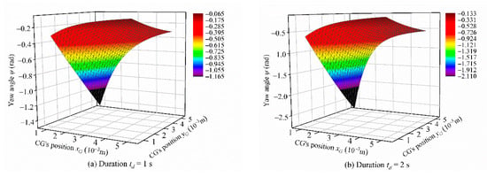
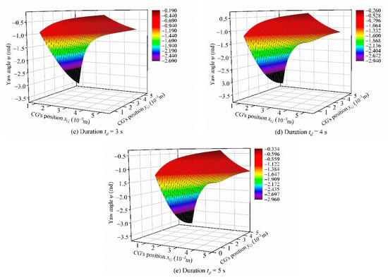
Figure 8.
The effect of CG’s position xG, yG, and duration td on yaw angle ψ.
As shown in Figure 8, the yaw angle ψ is affected by xG, yG, and td. Overall, ψ always increases monotonously with increasing td regardless of the changes of xG and yG, while the relationship between ψ, xG, and yG is not monotonous. In particular, when td is small (according to Figure 8a,b and simulation results), the tendency of ψ with changing xG or yG is quite similar. The ψ decreases with increasing xG and the amount of change of ψ is greater when yG is large. The ψ increases as yG increases and when xG is small, ψ is greatly affected by yG. Although ψ still increases with increasing yG when xG is large, the amount of change is quite small. When td increases, the changing trend of ψ is slightly different from the results when td is small (according to Figure 8c–e, and simulation results): ψ increases more with increasing yG when xG is small, and ψ still significantly increases with increasing yG while the amount of change of ψ becomes smaller when xG is large.
The simulation of the steering motion of “LUNA” was carried out by using PID (Proportional-Integral-Derivative) control and LQI control [11], and the calculated results showed that the performance of LQI control was better than that of PID control. Although it can be seen from this research that the radius of LUNA’s steering motion is much smaller than that of the TTUG, it still does not play the full advantage of DTUG’s disc shape. To further develop the structural characteristics of DTUG’s disc shape, the in situ steering motion is proposed in this paper and can be completed by adjusting only the attitude adjustment system. The 180-degree in situ steering motion of DTUG was simulated in Matlab and Simulink, and the results are shown in Figure 9. Note that Figure 9a selects the change of the position of the DTUG’s CG in the inertial frame as the observation object, the purpose is to intuitively reflect the state change of the in situ steering motion. Compared with the LUNA’s steering motion controlled by the LQI controller in Figure 6b, the DTUG’s yaw angle changed rapidly, and the time taken to reach the target angle was short. Since DTUG has not yet added a controller, its motion trajectory is relatively rigid. In contrast, the LUNA trajectory was smoother, but it can still reflect the characteristics of the DTUG’s in situ steering motion. Furthermore, the net buoyancy was set to zero. The DTUG can realize the 180-degree steering action in the tiny horizontal plane without movement in the vertical direction, which saves a lot of space compared with LUNA and further exerts the advantages of DTUG’s disc shape.
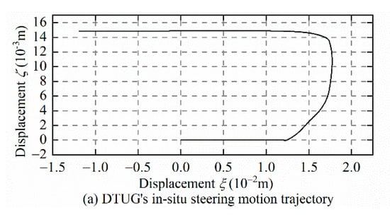
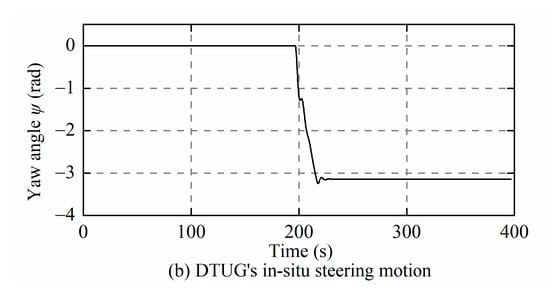
Figure 9.
Steering motion of DTUG and LUNA.
In order to visually show the difference between DTUG’s conventional steering motion and in situ steering motion, take a 20-degree change in yaw angle as an example, set the net buoyancy m0 to 0.4 kg, xG to 0.002 m, and td to 5.2 s, and the change of yG is as follows:
Then, the conventional steering motion simulation was carried out in the Matlab, and the results are shown in Figure 10. Based on the simulation results in Figure 8, the time evolution of the yaw angle (change by 20 degrees) of the in situ steering motion could be obtained, and the results are also shown in Figure 10.
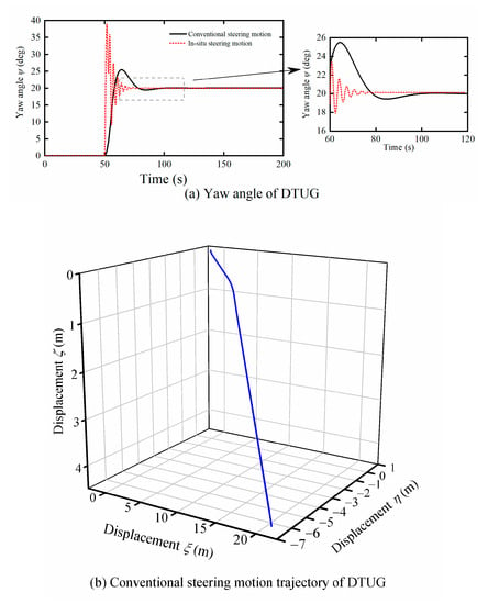
Figure 10.
Yaw angle and motion trajectory of DTUG.
Figure 10a shows the DTUG’s yaw angle’s time evolution through conventional steering motion and in situ steering motion when the yaw angle changed by 20 degrees. As shown in the figure, DTUG began to adjust its yaw angle from 50 s. When using conventional steering motion mode, DTUG reached the target angle in about 105 s. During the whole process, the change of the yaw angle was relatively flat. Although there were fluctuations near the target angle, the amplitude was small; when using in situ steering motion mode, DTUG reached the target angle at approximately 75 s. During the whole process, the DTUG’s yaw angle changed rapidly throughout the process and fluctuated around the target angle due to large steering angular velocity. Since there was no controller used in this simulation, the in situ steering motion curve had a lot of overshoot, which will be resolved after adding a suitable controller. Figure 10b shows the trajectory when DTUG adopted the conventional steering motion mode. As shown in the figure, the conventional steering motion requires a large space, while the in situ steering motion does not produce linear displacement. From this comparison, it can be seen that the in situ steering motion of DTUG has the advantages of quick response to control commands and space saving. These advantages further exert the disc shape’s structural characteristics, making DTUG more suitable for operation in small bodies of water with limited depth.
3.3. Sensitivity Analysis
Section 3.2.2 analyzed the influence of control parameters (xG, yG, and td) on the in situ steering motion. The results revealed that the control parameters significantly impact the performance (ψ) of the DTUG’s in situ steering motion. However, it cannot reflect which control parameter is most important to the motion performance. Usually, in this case, sensitivity analysis is adopted to study the importance of control parameters to the glider [41]. Therefore, the purpose of this section is to study the importance of the influence of control parameters (xG, yG, and td) on the motion performance (ψ) of the DTUG through sensitivity analysis. In practical applications of UGs, it is not enough to know only the control parameters that affect its motion performance. To make full use of the UG’s motion performance and achieve more accurate motion control, it is also necessary to know the sensitivity of the UG’s motion performance to control parameters. In this study, a sensitivity analysis was performed on the in situ steering performance of the DTUG, including local sensitivity analysis and global sensitivity analysis. Although more and more researchers use the global sensitivity analysis, the local sensitivity analysis still has reference value. In this paper, the global sensitivity analysis analyzed the global effect of various parameters on the DTUG’s in situ steering motion performance, rather than being limited to a certain point. In contrast, the local sensitivity analysis mainly analyzed the local effect of the control parameters on the DTUG’s motion performance at a certain point. The effect of a single parameter on motion performance can be obtained under the premise of ensuring that other parameters remain unchanged.
In summary, the global sensitivity analysis can be used to guide how to obtain the desired motion performance when multiple control parameters are changed cooperatively. When other parameters are determined, a local sensitivity analysis is needed to guide how to adjust a single parameter to obtain the expected motion performance. This study aimed to understand the effect of control parameters on the DTUG’s in situ steering motion performance more clearly through two sensitivity analyses so that the DTUG can be accurately determined according to different operating environments and tasks.
3.3.1. Local Sensitivity Analysis
The variable Sx, Sy, and St are defined to represent the sensitivity coefficient of ψ changing with xG, yG, and td, respectively. The calculation method is to keep two of these three variables constant so that the sensitivity coefficient of ψ to the third variable can be calculated. When analyzing the sensitivity of ψ to a variable, only one variable changed so that the local sensitivity analysis method could be adopted. The equation for calculating the sensitivity coefficient based on the Morris screening method is as follows:
where S is the sensitivity coefficient. Yi and Yi+1 are the output values of the i(th) and i+1(th) times run of the model. Y0 is the initial value for the calculation result. Pi and Pi+1 are the percentage changes of the i(th) and i+1(th) times operation parameter value relative to the rate parameter value, respectively. The n is the number of model runs.
Set td to vary from 1 s to 5 s, with a variation of 0.2 s per change, and set xG and yG to vary from 0.001 m to 0.005 m, with a variation of 0.0002 m per change. Then, these multiple sets of data were inputted to the Simulink and calculated. Finally, the sensitivity coefficient of ψ on the variation of xG, yG, and td could be calculated based on the simulation results, respectively, and the results are shown in Figure 11.
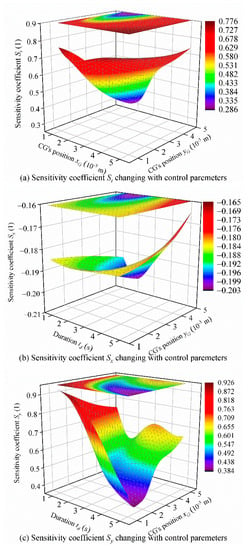
Figure 11.
Sensitivity coefficients of the DTUG.
As shown in Figure 11a, St decreases first with increasing xG and then increases rapidly, and the amount of change of St is larger when yG is large. When xG is small, St decreases with increasing yG, and when xG is large, St still decreases with increasing yG while the amount of change is quite small. Figure 11b shows that when yG is small, Sx increases first with increasing td and decreases slowly. When yG is large, Sx increases rapidly with increasing td and then decreases rapidly. When td is small, Sx increases with increasing yG while Sx decreases rapidly as yG increases when td is large. Figure 11c shows that when xG is small, Sy decreases rapidly with increasing td. When xG is large, Sy decreases rapidly with increasing td and then increases. When td is large, Sy increases with increasing xG while Sy decreases rapidly as xG increases when td is small. The local sensitivity analysis reflects the variation in sensitivity of the in situ steering motion to a single variable. In contrast, the remaining two variables were unchanged, which is of great significance for guiding DTUG on adjusting a single control parameter to better control the in situ steering motion.
3.3.2. Global Sensitivity Analysis
The local sensitivity analysis is carried out in this section, and the result reflects the effect of a single variable on the yaw angle ψ. To further study the importance of the effect of the variables on the yaw angle, the first-order and global sensitivity coefficients of xG, yG, and td on the ψ are calculated based on the Sobol global sensitivity analysis method. Sobol method is a kind of Monte Carlo method based on variance [41,42]. Let variable Si (i = 1, 2, 3) and STi (i = 1, 2, 3) represent the first-order sensitivity coefficient and global sensitivity coefficient of ψ change to the xG, yG, and td, respectively. Set td to vary between 1 s and 5 s and set xG and yG to vary between 0.001 m and 0.005 m. These parameters are considered to be uniformly distributed within the range of values. The parameters’ values can be obtained by using the Latin hypercube sampling method [42,43]. In this study, the number of samples (N) varied from 0 to 150,000, and the number of independent variables was 3 (D = 3).
The motion control equations of DTUG can be expressed as Y = f (X), X = (x1, x2, x3), where x1, x2, and x3, respectively, represent the three control parameters that affect the yaw angle: xG, yG, and td. Then, the Latin hypercube sampling method can be used to generate a N × 2D sample matrix. Set the columns 1 to D of the sample matrix to a matrix A, and columns D + 1 to 2D to a matrix B. Replace the i-th column of matrix A with the i-th column of matrix B to construct the matrix ABi of N × D (i = 1,2...D). After these three steps, five matrices of A, B, AB1, AB2, and AB3 are constructed, and there are sets of input data of xG, yG, and td, so there will be 20 sets of Y values. The above data are brought into the motion control equations of DTUG, and the corresponding Y value matrix can be obtained according to the input data: .
The calculation formulas for the first-order sensitivity coefficient and the global sensitivity coefficient are as follows:
where
Note that YA + YB means to create a new matrix of 2N × D composed of YA and YB. According to Equation (19) and the results of the in situ steering motion simulations, the first first-order sensitivity coefficient and the global sensitivity coefficient can be calculated with different sample size N. The results are shown in Figure 12 and Figure 13. It can be seen that when N is greater than 120,000, the sensitivity coefficients of each parameter converge. Take the graph results’ average to obtain the first-order sensitivity coefficient and global sensitivity coefficient of each parameter shown in Table 5.
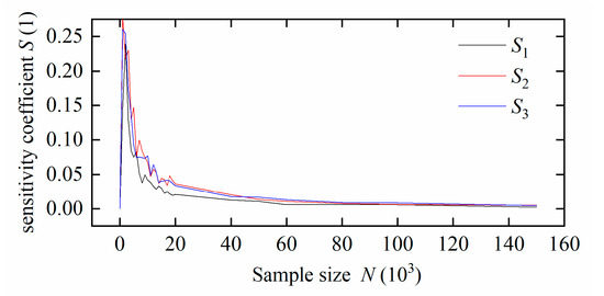
Figure 12.
First-order sensitivity coefficient with changing sample size.
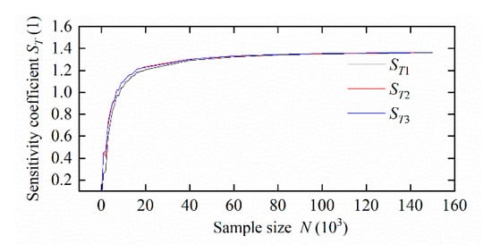
Figure 13.
Global sensitivity coefficient with changing sample size.

Table 5.
First-order sensitivity coefficient and global sensitivity coefficient of each parameter.
The results show that xG, yG, and td have significant effects on the in situ steering motion of the DTUG within the value range of the variables, which validates the local sensitivity analysis results. Among these three variables, the first-order sensitivity coefficient and the global sensitivity coefficient of yG were at a high level, followed by td, and xG is the smallest. Note that these three values are very close to each other. Additionally, we also present the time evolution of yaw angle with only one parameter changing. Set the control parameters for the base value as xG = 0.002 m, yG = 0.001 m, and td = 2 s. Then increase xG, yG, and td by 10%, respectively, and the corresponding change in the yaw angle can be obtained. The results are shown in Figure 14. Combining Table 5 and Figure 14, show that the sensitivity of the yaw angle to yG and td is very close, slightly larger than xG.
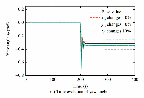
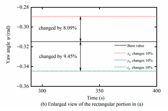
Figure 14.
Time evolution of yaw angle with no parameter changes.
The global sensitivity analysis, local sensitivity analysis, and the in situ steering motion simulation can be used to guide the DTUG to select the most appropriate combination of control parameters in the in situ steering motion to meet the requirements of different environments and different tasks. For example, if the DTUG needs to steer quickly, a scheme of appropriately reducing xG and td and increasing yG can be adopted; if the yaw angle of the DTUG needs to be changed greatly, a scheme of preferentially adjusting yG and td can be adopted. Also, the results of sensitivity analysis can be used to guide DTUG’s structural parameter optimization and motion controller design. In the optimization design of the DTUG, the sensitivity analysis results can be referenced to appropriately adjust the parameters that have the greatest impact on the in situ steering motion to achieve better performance. Simultaneously, when designing the in situ steering motion controller, the control strategy can be formulated according to the importance of the control parameters to achieve the set goal in the shortest time or to achieve precise control by adjusting the control parameters that have little effect on the DTUG’s motion performance.
3.4. Stability Analysis
As shown in Figure 7b, there are two steps for DTUG to complete the in situ steering motion: The pitch motion and steering motion. As one of the typical motions of the UG, the pitch motion has good stability, and the highly symmetrical full-wing shape of the DTUG is also conducive to improving its stability [17]. Thus, the stability of steering motion after DTUG’s pitch motion is mainly analyzed in this section based on the Lyapunov stability theory [25,44]. The dynamic model of DTUG for the in situ steering motion was linearized first, and then the linearized state–space equation was established. Finally, the real part of each linear eigenvalue could be obtained by using the Lyapunov first method and used for analyzing the stability of the in situ steering motion.
3.4.1. Dynamic Model Linearization
DTUG can realize the in situ steering motion without generating the linear displacements (ξ, η, ζ). The corresponding linear velocities (u, v, and w) in the body frame are also zero. The DTUG state parameters can be set as {u, v, w} = {0, 0, 0}, and the dynamic model of the in situ steering motion be simplified from Equation (17), as shown in Equation (20).
where
K = −(Izz − Iyy + A55 − A66)qr − myGgcφcθ − mzGgsφcθ + Kpp + Kp|p|p|p|,
M = −(Ixx − Izz + A44 − A66)pr − mxGgcφcθ − mzGgsθ + Mww + Mq|q|q|q|,
N = −(Iyy − Ixx − A44 + A55)pq − mxGgsφcθ − myGgsθ + Nrr + Nr|r|r|r|.
Take yG as the control parameter as an example. Thus, set the control parameter c = [yG] and set the state variable . Solve the partial derivatives of Equation (20) for p, q, and r, respectively, as shown in Equation (21) [45].
Therefore, the Jacobian matrix A of DTUG at equilibrium point pairs p, q, and r can be obtained:
where
and the Jacobian matrix C of the DTUG at the equilibrium point pair φ and θ can also be obtained based on the same method:
where
Solve the partial derivatives of (19) for the control parameter c, as shown in Equation (24):
Based on the above analysis, the linearized state–space equation of the DTUG can be established:
where
o1×2 = [0, 0], o1×3 = [0, 0, 0],
I1×2 = [1, 0], I1×3 = [0, 0, 1],
3.4.2. Lyapunov Stability Analysis
Set the DTUG control parameter xG = 0.005 m and yG varies from 0.001 to 0.008 m. Then the real part of each eigenvalue of A with changing yG can be obtained by using the Lyapunov first method, as shown in Figure 15. The same calculation method was adopted to analyze the stability of DTUG with xG as the control parameter (c = [xG]), and the results are shown in Figure 15. Note that the vector Q should be replaced with Q1 when xG is the control parameter:
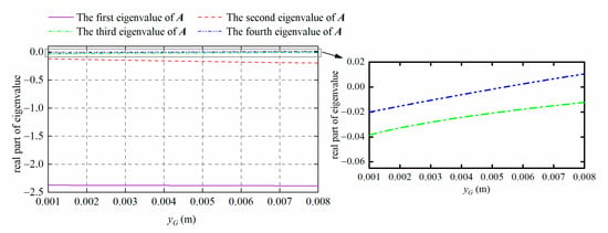
Figure 15.
Motion stability with changing yG.
It can be seen from Figure 15 and Figure 16 that when the control parameter yG is within the range of 0.001~0.005 m, the real parts of each eigenvalue of matrix A are less than zero. It indicates that DTUG can remain stable. The real part of each eigenvalue of A is greater than zero when yG is greater than 0.005 m, which means that DTUG is no longer stable. When the control parameter xG is within 0.001~0.008 m, the real part of each eigenvalue of A is less than zero. It indicates that the DTUG can remain stable when xG is with the range of 0.001~0.008 m.
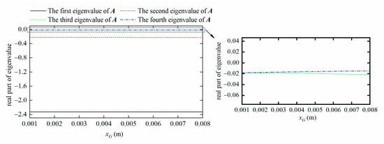
Figure 16.
Motion stability with changing xG.
3.4.3. Simulation on In Situ Steering Motion after Disturbance
This paper mainly focused on the impact of different control parameter inputs on DTUG’s motion (motion performance prediction), an open-loop control system. According to the viewpoint in [46], the stability under open-loop control refers to the glider’s stability to return to the initial state of motion after the glider is subjected to small disturbances. This is very important to guide the selection of the DTUG’s control parameters because inappropriate control parameters will cause the glider to lose stability. Therefore, the stability of the DTUG under open-loop control was analyzed in this paper based on the Lyapunov’s first theorem. In this section, we designed some simulation cases to study the variation of the yaw angle of DTUG after a small disturbance, and such a disturbance term can be an external moment. We included an Nd term in the DTUG motion control equations. Assuming that the DTUG first performs the in situ turning motion and the motion control equations are solved using the fourth-order Runge–Kutta method. After the yaw angle reaches the target angle, continue using the fourth-order Runge–Kutta method to solve the motion control equations with the external moment Nd applied for 2 s. When xG = 0.005 m, yG = 0.001 m, and td = 5 s, Figure 16 compares the time evolution of the yaw angle with different Nd values (0.5 N·m, 1.0 N·m, 1.5 N·m, 2.0 N·m).
As shown in Figure 17, it is obvious that the variation in the DTUG yaw angle and the time required to return to a constant value increases with increasing Nd, and the effect of this external disturbance can be reversed. Combining these results with Lyapunov’s stability analysis, it can be concluded that DTUG can remain stable within the range of control parameters.
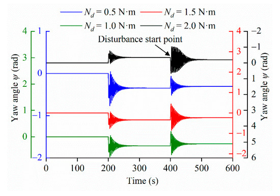
Figure 17.
Variation of yaw angle after an external disturbance.
4. Discussion
The simulations of the in situ steering motion, sensitivity analysis, and motion stability analysis of DTUG are carried out in this paper. The results show that DTUG (disc-type underwater glider) can realize the in situ steering motion while keeping stable. It seems that the in situ steering motion is simple, which can be achieved by keeping the net buoyancy to zero in the conventional steering motion. However, this kind of motion is extremely important for DTUG, especially in the small bodies of water. TTUGs (torpedo-type underwater gliders) are suitable for environmental monitoring and topographic surveys in a wide area of the open ocean.
In comparison, DTUGs are more maneuverable and have omnidirectional motion characteristics [15], suitable for investigation in small bodies of water with limited depth. At present, the design of UGs (underwater gliders) has always been limited by traditional aircraft design theory, that is, the air and hydrodynamic shapes of high-speed aircraft (such as aircraft, missiles, torpedoes, etc.) [47,48,49] are usually used to design the low-speed UGs. Under this design concept, the stability and maneuverability of the UGs are heavily dependent on high speed. However, low speed is an inherent characteristic of UGs. Although some research institutions have adopted hybrid driven [50,51], vector propulsion [52], and other methods to improve the maneuverability of UGs, it has also brought the disadvantages of high energy consumption and complex structure. Thus, how to improve the maneuverability and application area of the UG while maintaining a low speed is of great research value. The DTUG studied in this paper adopted a highly symmetrical disc-shape design with good motion performance in the small bodies of water and could also realize some motions that TTUG cannot achieve, such as vertical motion with zero pitch angle and in situ steering motion. To further develop the advantages and characteristics of the DTUG in the small bodies of water, this paper continues the previous research and further studies of the in situ steering motion characteristics of the DTUG, and the study in this paper is of great significance to comprehensively understand the DTUGs and expand the application of the UGs.
In terms of research content, this paper focused more on predicting the DTUG’s in situ steering motion, that is, the variation of DTUG motion performance under different control parameters, rather than the control effect of the motion controller. This research can be used to guide the control parameter optimization of DTUG and the design of the motion controller. In the future, the DTUG prototype test is planned to verify the research content of this paper.
5. Conclusions
In this paper, we established the motion control equations with control inputs for DTUG. Then, the motion stability was analyzed to measure the stability of the DTUG while operating. The in situ steering motion was proposed and simulated by the Matlab and Simulink. The simulation results were compared with the TTUG and the previous version of DTUG, and the following conclusions can be drawn.
(1) Like a TTUG, DTUG can complete the conventional steering motion through adjusting the moveable masses and net buoyancy; the difference is that the turning radius of DTUG is smaller than that of a TTUG. Furthermore, DTUG can also complete the in situ steering motion by adjusting the CG control system only without adjusting the net buoyancy zero. It cannot only reduce the difficulty of control but also reduce the energy consumption and improve the DTUG’s battery life. (2) Compared with a TTUG, DTUG’s in situ steering motion greatly reduces the UG’s steering motion’s horizontal space requirements. Compared with the conventional steering motion, DTUG can complete the same adjustment of the yaw angle through the in situ steering motion without the need for a large depth in the working waters. The yaw angle of DTUG changes rapidly, and the time required to reach the target angle is shorter than that of the conventional steering motion. The in situ steering motion further exerts the structural advantages of DTUG, which is more conducive to its application in small bodies of water. (3) The study shows that the in situ steering motion performance of DTUG is significantly affected by xG, yG, and td. The yaw angle changes monotonically with changing td, while the effect of xG or yG on the yaw angle is non monotonically and affected by two other control parameters. (4) The sensitivity analysis showed that the DTUG’s yaw angle is most sensitive to yG, and the results can be used to guide the adjustment of the control parameters, according to the specific environment and conditions of the DTUG, to better achieve the adjustment of the DTUG’s yaw angle. (5) DTUG can remain stable within the range of control parameters based on the Lyapunov stability analysis.
This paper focused on the theoretical and simulation analysis of DTUG in situ steering motion characteristics, which can guide for future experiments. Meanwhile, for further study and validation of the DTUG, a DTUG prototype is being constructed and will be tested to compare with those numerical simulation works performed in this paper.
Author Contributions
Conceptualization, H.Z., P.Y., and T.W.; investigation, H.Z. and X.J.; methodology, H.Z., Y.P., and X.J.; software, H.Z.; supervision, P.Y. and T.W.; writing—original draft, H.Z.; writing—review and editing, H.Z., P.Y., and X.J. All authors have read and agreed to the published version of the manuscript.
Funding
This research was funded by the National Key Research and Development Program of China, grant number 2016YFC0301500, the State Key Laboratory of Ocean Engineering (Shanghai Jiao Tong University), grant number 1904, and the Natural Science Foundation of Liaoning Province in 2020, grant number 2020-MS-125.
Conflicts of Interest
The authors declare no conflict of interest.
References
- Leonard, N.E.; Paley, D.A.; Lekien, F.; Sepulchre, R.; Fratantoni, D.M.; Davis, R.E. Collective motion, sensor networks, and ocean sampling. Proc. IEEE 2007, 95, 48–74. [Google Scholar] [CrossRef]
- Stommel, H. The slocum mission. Oceanography 1989, 2, 22–25. [Google Scholar] [CrossRef]
- Webb, D.C.; Simonetti, P.J.; Jones, C.P. SLOCUM: An underwater glider propelled by environmental energy. IEEE J. Ocean. Eng. 2001, 26, 447–452. [Google Scholar] [CrossRef]
- Eriksen, C.C.; Osse, T.J.; Light, R.D.; Wen, T.; Lehman, T.W.; Sabin, P.L.; Ballard, J.W.; Chiodi, A.M. Seaglider: A long-range autonomous underwater vehicle for oceanographic research. IEEE J. Ocean. Eng. 2001, 26, 424–436. [Google Scholar] [CrossRef]
- Sherman, J.; Davis, R.E.; Owens, W.; Valdes, J. The autonomous underwater glider “Spray”. IEEE J. Ocean. Eng. 2001, 26, 437–446. [Google Scholar] [CrossRef]
- Rudnick, D.L.; Davis, R.E.; Eriksen, C.C.; Fratantoni, D.M.; Perry, M.J. Underwater gliders for ocean research. Mar. Technol. Soc. J. 2004, 38, 73–84. [Google Scholar] [CrossRef]
- D’Spain, G.L.; Jenkins, S.A.; Zimmerman, R.; Luby, J.C.; Thode, A.M. Underwater acoustic measurements with the Liberdade/X-Ray flying wing glider. J. Acoust. Soc. Am. 2005, 117, 2624. [Google Scholar] [CrossRef]
- Buisson, N. BRIDGES project: DXP and UXP gliders bring together research and industry for the development of glider environment services. In Proceedings of the OCEANS 2019-Marseille, Marseille, France, 17–20 June 2019; IEEE: Marseille, France, 2019. [Google Scholar]
- Osse, T.J.; Eriksen, C.C. The Deepglider: A full ocean depth glider for oceanographic research. In Proceedings of the OCEANS 2007, Vancouver, BC, Canada, 29 September–4 October 2007; IEEE: Vancouver, BC, Canada, 2008. [Google Scholar]
- Claustre, H.; Beguery, L. SeaExplorer glider breaks two world records. Sea Technol. 2014, 55, 19–21. [Google Scholar]
- Nakamura, M.; Hyodo, T.; Koterayama, W. “LUNA” testbed vehicle for virtual mooring. In Proceedings of the Seventeenth International Offshore and Polar Engineering, Lisbon, Portugal, 1–6 July 2007; International Society of Offshore and Polar Engineers: Lisbon, Portugal, 2007. [Google Scholar]
- Nakamura, M.; Koterayama, W.; Inada, M.; Marubayashi, K.; Hyodo, T.; Yoshimura, H.; Morii, Y. Disk-type underwater glider for virtual mooring and field experiment. Int. J. Offshore Polar Eng. 2009, 19, 66–70. [Google Scholar]
- Nakamura, M.; Koterayama, W.; Ito, Y.; Matsuno, A.; Noda, J.; Morii, Y.; Yamawaki, N.; Shimizu, K. Oceanographic observation by disk type underwater glider for virtual mooring. In Proceedings of the 27th International Ocean and Polar Engineering Conference, San Francisco, CA, USA, 25–30 June 2017; International Society of Offshore and Polar Engineers: San Francisco, CA, USA, 2017. [Google Scholar]
- Nakamura, M.; Noda, J.; Kajiwara, H.; Shinkai, Y. Study of influence of vertical tail wing of disk-type underwater glider on motion control. In Proceedings of the 28th International Ocean and Polar Engineering Conference, Sapporo, Japan, 10–15 June 2018; International Society of Offshore and Polar Engineers: Sapporo, Japan, 2018. [Google Scholar]
- Yu, P.Y.; Wang, T.L.; Zhou, H.; Shen, C. Dynamic modeling and three-dimensional motion simulation of a disk type underwater glider. Int. J. Nav. Archit. Ocean Eng. 2018, 10, 318–328. [Google Scholar] [CrossRef]
- Zhu, Y.D. Analysis of Motion and Bottom Sitting Performance of the Dish Shaped Underwater Glider. Master’s Thesis, Dalian Maritime University, Dalian, China, 2017. [Google Scholar]
- Zhou, H.; Wang, T.L.; Sun, L.; Lan, W. Study on the vertical motion characteristics of disc-type underwater gliders with zero pitch angle. J. Mar. Sci. Technol. 2019, 25, 828–841. [Google Scholar] [CrossRef]
- Zhang, C. The Design and Motion Control of Round Dish-Shaped Underwater Vehicle. Master’s Thesis, Harbin Engineering University, Harbin, China, 2013. [Google Scholar]
- Wang, T.; Ye, X.F.; Wang, L.; Li, H. Grid search optimized SVM method for dish-like underwater robot attitude prediction. In Proceedings of the 2012 Fifth International Joint Conference on Computational Sciences and Optimization, Harbin, China, 23–26 June 2012; IEEE: Harbin, China, 2012. [Google Scholar]
- Yu, P.Y.; Shen, C.; Wang, T.L.; Zhang, B.R. Research on shape design of disk type of underwater glider. Shipbuild. China 2018, 59, 42–50. [Google Scholar]
- Zhao, B.Q. Study of modeling and simulation of disc-underwater glider dynamic stability. Ship. Sci. Technol. 2016, 38, 82–86. [Google Scholar]
- Wang, H.L.; Wang, D.; Wang, T.L.; Zhang, Y.B.; Gu, N. Adaptive cooperative diving of saucer-type underwater gliders subject to model uncertainties and input constraints. IEEE Access 2019, 7, 60042–60054. [Google Scholar] [CrossRef]
- Jin, X. Research on Formation Change and Path Planning of the Multi-Underwater-Glider System. Master’s Thesis, Dalian Maritime University, Dalian, China, 2018. [Google Scholar]
- Zhou, H.; Wang, T.L.; Yu, P.Y. Simulation of the motion of disc type underwater glider. J. Harbin Eng. Univ. 2019, 40, 696–702. [Google Scholar]
- Bhatta, P.; Naomi, E.L. Nonlinear gliding stability and control for vehicles with hydrodynamic forcing. Automatica 2008, 44, 1240–1250. [Google Scholar] [CrossRef]
- Kan, L.; Zhang, Y.W.; Fan, H.; Yang, W.G.; Chen, Z.K. MATLAB-based simulation of buoyancy-driven underwater glider motion. J. Ocean. Univ. China 2008, 8, 117–122. [Google Scholar] [CrossRef]
- Yang, C.J.; Peng, S.L.; Fan, S.S. Performance and stability analysis for ZJU glider. Mar. Technol. Soc. J. 2014, 48, 88–103. [Google Scholar] [CrossRef]
- Zhang, S.W.; Yu, J.C.; Zhang, A.Q.; Zhang, F.M. Spiraling motion of underwater gliders: Modeling, analysis, and experimental results. Ocean. Eng. 2013, 60, 1–13. [Google Scholar] [CrossRef]
- Cao, J.J.; Cao, J.L.; Yao, B.H.; Lian, L. Three dimensional model, hydrodynamics analysis and motion simulation of an underwater glider. In Proceedings of the IEEE OCEANS 2015, Genova, Italy, 18–21 May 2015; IEEE: Genova, Italy, 2015. [Google Scholar]
- Liu, F.; Wang, Y.H.; Wu, Z.L.; Wang, S.X. Motion analysis and trials of the deep sea hybrid underwater glider Petrel-II. China Ocean. Eng. 2017, 31, 55–62. [Google Scholar] [CrossRef]
- Fan, S.S.; Woolsey, C.A. Dynamics of underwater gliders in currents. Ocean. Eng. 2014, 84, 249–258. [Google Scholar] [CrossRef]
- Gu, J.N.; Li, Q.J.; Gao, L.; Zhang, Z.H. Modeling and simulation of the motion performance of underwater glider. J. Huazhong Univ. Sci. Tech. 2016, 44, 76–80. [Google Scholar]
- Wang, J.Q.; Wang, C.; Wei, Y.J.; Zhang, C.J. Hydrodynamic characteristics and motion simulation of flying-wing dish-shaped autonomous underwater glider. J. Harbin Inst. Technol. 2018, 50, 131–137. [Google Scholar]
- Yu, P.Y.; Shen, C.; Zhen, C.B.; Wang, T.L. Analysis of the steady spiral motion of an underwater glider on temporal and spatial scales. Ship. Sci. Technol. 2019, 41, 71–75. [Google Scholar]
- Zhou, H.; Wang, T.L.; Yu, P.Y. Study on motion characteristics of disc type underwater glider. J. Huazhong Univ. Sci. Tech. (Nat. Sci. Ed.) 2019, 46, 112–118. [Google Scholar]
- Eichhorn, M. Optimal routing strategies for autonomous underwater vehicles in time-varying environment. Rob. Auton. Syst. 2013, 67, 33–43. [Google Scholar] [CrossRef]
- Fossen, T.I. Handbook of Marine Craft Hydrodynamics and Motion Control; John Wiley & Sons: New York, NY, USA, 2011. [Google Scholar]
- Zhou, H. Research on the Motion Performance of the Disk Type Underwater Glider. Master’s Thesis, Dalian Maritime University, Dalian, China, 2017. [Google Scholar]
- Wang, T. Reaearches on a Novel Disk-like Underwater Robot and Attitude Predictive Control. Ph.D. Thesis, Harbin Engineering University, Harbin, China, 2013. [Google Scholar]
- Asakawa, K.; Nakamura, M.; Hyakudome, T.; Maeda, Y.; Ishihara, Y. Spiral gliding experiments of the underwater glider for long-term observation. In Proceedings of the OCEANS 2018 MTS/IEEE Charleston, Charleston, SC, USA, 22–25 October 2018; IEEE: Charleston, SC, USA, 2018. [Google Scholar]
- Wang, S.X.; Song, Y.; Wang, Y.H.; Niu, W.D.; Lei, Z. Sensitivity analysis of energy consumption parameters for petrel-II underwater glider based on sobol’ method. J. Tianjin Univ. (Sci. Technol.) 2017, 50, 113–119. [Google Scholar]
- McKay, M.D.; Beckman, R.J.; Conover, W.J. A comparison of three methods for selecting values of input variables in the analysis of output from a computer code. Technometrics 2000, 42, 55–61. [Google Scholar] [CrossRef]
- Helton, J.C.; Davis, F.J. Latin hypercube sampling and the propagation of uncertainty in analyses of complex systems. Reliab. Eng. Syst. Saf. 2003, 81, 23–69. [Google Scholar] [CrossRef]
- Bhatta, P.; Leonard, N.E. A Lyapunov function for vehicles with lift and drag: Stability of gliding. In Proceedings of the 2004 43rd IEEE Conference on Decision and Control (CDC) (IEEE Cat. No. 04CH37601), Nassau, Bahamas, 14–17 December 2004. [Google Scholar]
- Wang, Y.H. Dynamical Behavior and Robust Control Strategies of the Underwater Gliders. Ph.D. Thesis, Tianjin University, Tianjin, China, 2007. [Google Scholar]
- Zhao, B.Q.; Wang, X.H.; Yao, B.H.; Lian, L. Lyapunov stability of the underwater glider. J. Harbin Eng. Univ. 2015, 36, 83–87. [Google Scholar]
- Graver, J.G. Underwater Gliders: Dynamics, Control and Design. Ph.D. Thesis, Princeton University, Princeton, NJ, USA, 2005. [Google Scholar]
- Asakawa, K.; Nakamura, M.; Kobayashi, T.; Watanabe, Y.; Kojima, J. Design concept of Tsukuyomi Underwater glider prototype for virtual mooring. In Proceedings of the Oceans 2011, Santander, Spain, 6–9 June 2011; IEEE: Santander, Spain, 2011. [Google Scholar]
- Hussain, N.A.A.; Chung, T.M.; Arshad, M.R.; Mokhtar, R.M.; Abdullah, M.Z. Design of an underwater glider platform for shallow-water applications. Int. J. Intell. Def. Support Syst. 2010, 3, 186. [Google Scholar] [CrossRef]
- Niu, W.D.; Wang, S.X.; Wang, Y.H.; Song, Y.; Zhu, Y.Q. Stability analysis of hybrid-driven underwater glider. China Ocean. Eng. 2017, 31, 528–538. [Google Scholar] [CrossRef]
- Chen, Z.; Yu, J.C.; Zhang, A.Q.; Zhang, F.M. Design and analysis of folding propulsion mechanism for hybrid-driven underwater gliders. Ocean. Eng. 2016, 119, 125–134. [Google Scholar] [CrossRef]
- Ge, Z.; Ji, G.R.; Yan, P.; Qin, F.L.; Li, G.Q. Research on movement performance of a vector propulsion autonomous underwater vehicle. In Proceedings of the Oceans 2019, Marseille, France, 17–20 June 2019; IEEE: Marseille, France, 2019. [Google Scholar]
© 2020 by the authors. Licensee MDPI, Basel, Switzerland. This article is an open access article distributed under the terms and conditions of the Creative Commons Attribution (CC BY) license (http://creativecommons.org/licenses/by/4.0/).