1. Introduction
Offshore wind energy offers immense possibilities such that the total offshore wind power generation capacity is expected to grow to 75 GW by 2020. However, the offshore wind energy industry has been hampered by high capital costs [
1]. Construction and offshore installation costs of offshore wind farms are in the range of 3 million EUR/MW and generally account for one-third to half of the total cost, while the rest of the costs come from the construction of infrastructure, such as manufacturing facilities, installation vessels, and maintenance [
2].
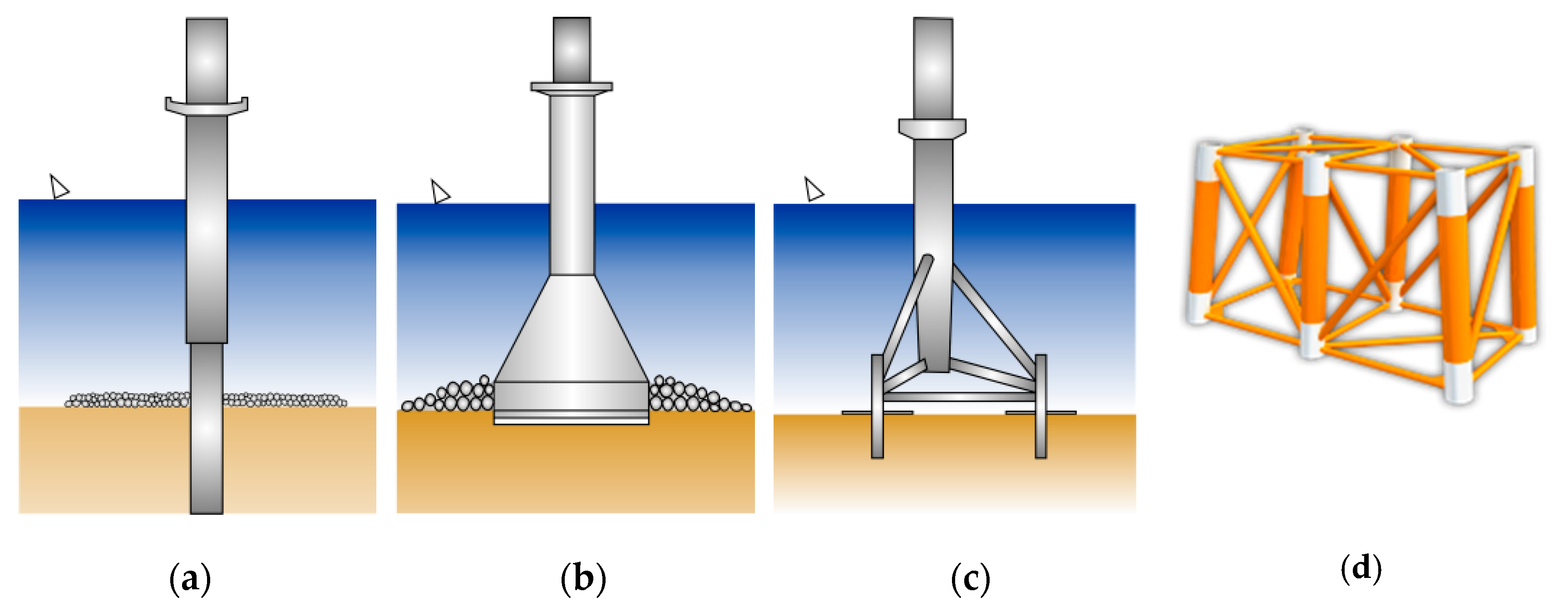
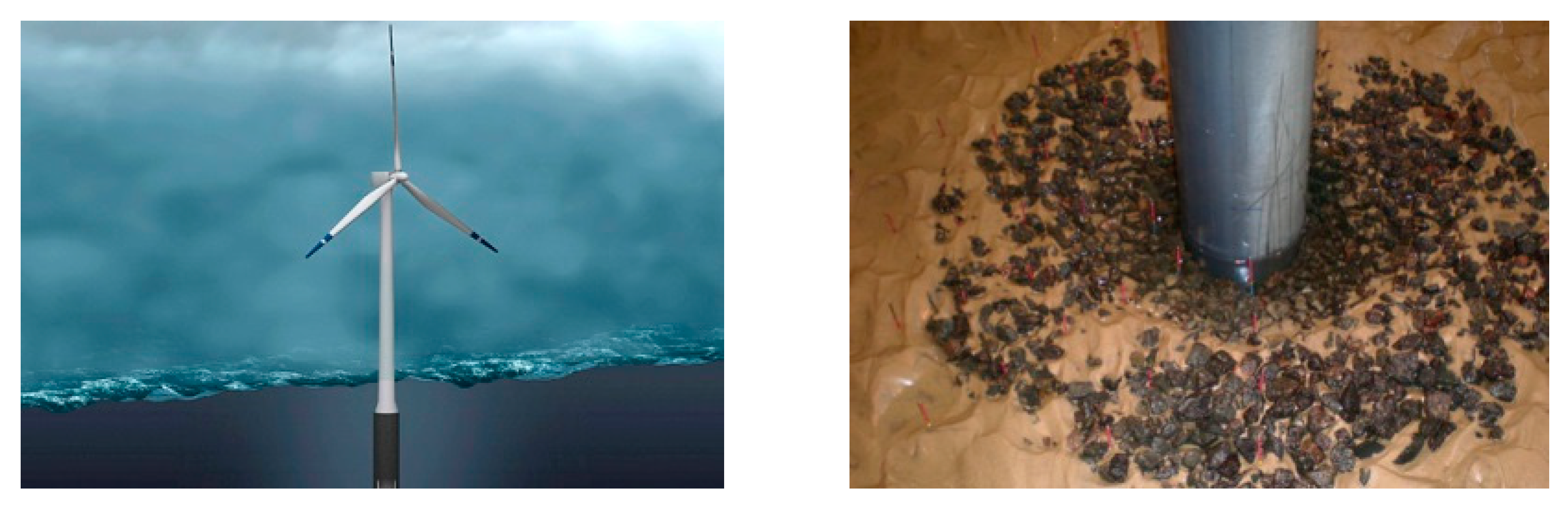
Although the development of a floating type of offshore wind turbine for deep water is nearly complete, most offshore wind farms still rely on the traditional fixed bottom substructure, such as a mono-pile, gravity, tripod, and steel jacket foundation (see
Figure 1) [
3]. Of these substructures, the mono-pile foundation has been preferred [
3] because it can most easily be produced, assembled, and deployed, and is less expensive. The mono-pile foundation is a type of substructure consisting of a single pile that usually penetrates to a depth of 10–40 m from the sea bottom based on the load applied to the wind turbine. Once the installation is complete, a mono-pile rises 40–60 m above mean sea level to surpass the atmospheric boundary layer where the wind velocities are retarded due to energy dissipation. The wind turbine is mounted near the top of the mono-pile. Hence, the mono-pile must support the wind turbine and the wave load acting on it.
Many offshore wind farms at the planning stage in South Korea are going to be installed in shallow waters using mono-pile foundations where the water depths range from 10 to 30 m and are generally located 12 km off the shore [
4]. The coastal sediments in these areas usually consist of silt and clay, and make the seabed very mobile [
5]. At such locations, the interactions of wave and current with the mono-pile have a significant effect on the total environmental load by nearly 50%. One of the most prominent risks to offshore wind farms is known to be scouring due to waves and currents. The deployment of offshore wind farms in shallow waters can disturb the flow pattern in its immediate neighborhood, and increase the local sediment transport. When the scouring is excessive, it can jeopardize the offshore wind farms’ safety because its substructure can be exposed to a significantly increased hydrodynamic loading due to the increased depth [
6]. Furthermore, once a pool is formed around the foundation by a horseshoe vortex, a streaming, and a large eddy, the offshore wind turbine is subject to subtle vibrations, which eventually lead to fatigue failure of the offshore wind farms. In order to prevent the disaster mentioned above, the mono-pile needs to be protected against scouring. As of now, it takes nearly 80,000–150,000 EUR for each offshore wind turbine, which is expensive enough to act as an extra burden to offshore wind projects that are already suffering from excessive capital costs [
7].
Over the last decades, many studies have been conducted on the scour around the mono-pile. The research achievements are considerable, and the failure mechanism of scour protections around a mono-pile has been identified [
8,
9]. On the other hand, scour protection of the mono-pile has received less attention than the scour, and the research achievements mentioned above have not yet been fully integrated into the development of more efficient scour protection. As a result, protection against scouring still heavily relies on rocks [
3,
10,
11], and usually consist of layers of rock armor placed on the apron of a mono-pile designed to survive against the steady current that represents harsh environmental conditions [
12]. In the design process of scour protection based on rocks, the dynamic nature of the interaction of incident waves with a mono-pile and seabed has not yet been fully accounted for [
13]. Considering the hydraulic characteristics around the offshore wind farms such as a horseshoe vortex, a streaming, and a large eddy, the conventional scour protection using multiple layers of rock armor seems ineffective. Therefore, there is much room for improvement.
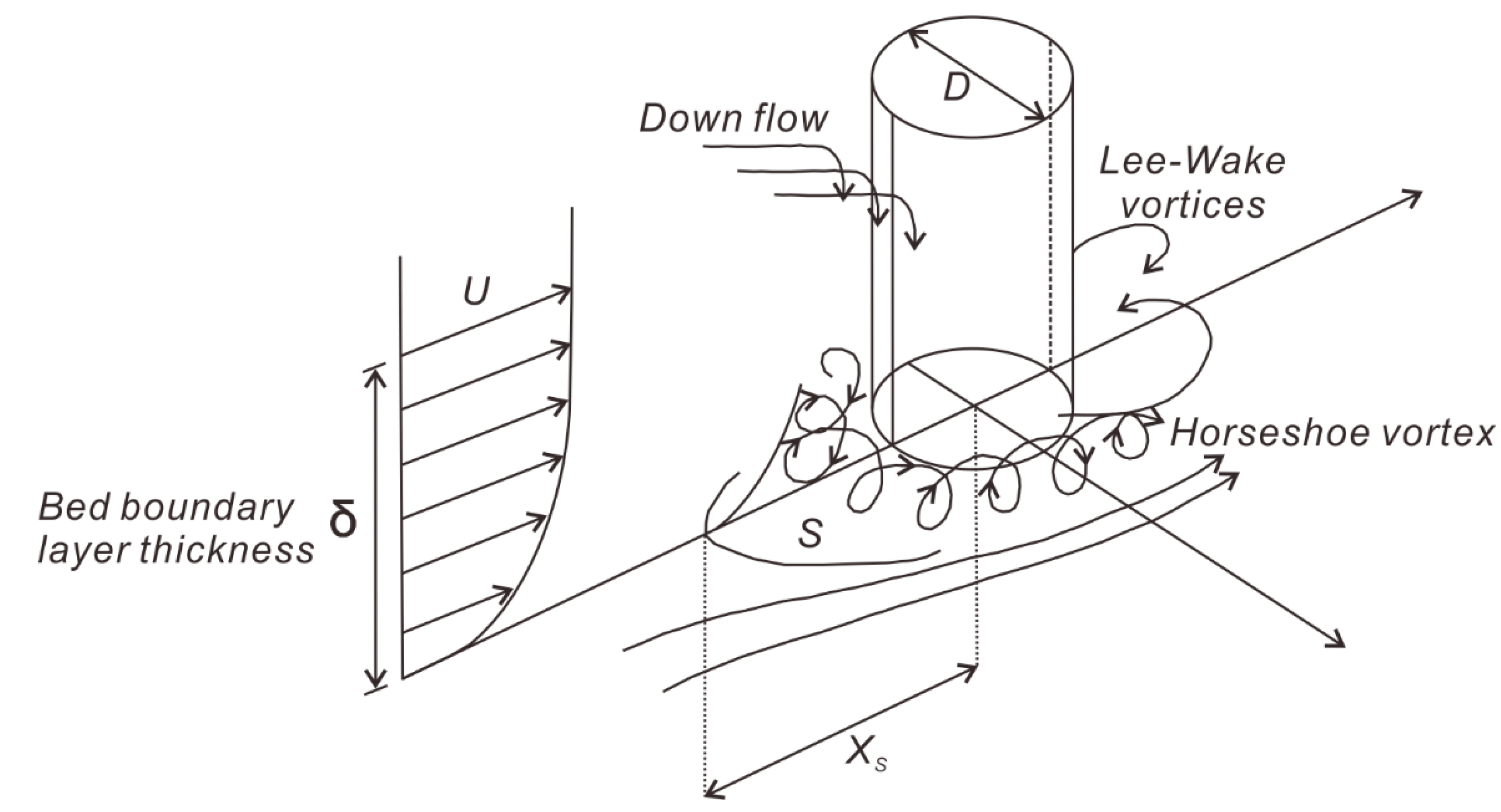
In this rationale, this study intends to develop a more reasonable scour protection to make the offshore wind energy industry more cost competitive. After a thorough review, we note that a horseshoe vortex, a streaming, and a large eddy are responsible for the scouring in the vicinity of offshore wind farms [
14]. Among these, the horseshoe vortex is a crucial flow feature governing the scouring [
14,
15,
16], which becomes fiercer once standing waves form in front of offshore wind farms due to reflection. Hence, we decided to pursue efficient scour protection, which can minimize these causative forces of scouring rather than elaborating on the scour protection in line with multiple layers of rock, which is expensive and inefficient. In this rationale, we propose a hybrid mono-pile with a light turbine mounted to the lower portion of a mono-pile, which can lower the reflection from the offshore wind farms by converting a significant portion of incoming wave energy into mechanical energy. It is easily perceived that a weakened standing wave in this manner can lead to less horseshoe vortex, streaming, and scouring.
In order to verify the scouring control effects of hybrid mono-pile proposed in this study, we also carry out the numerical simulation using FLOW-3D [
17]. The hydrodynamic module in FLOW-3D is based on the Navier–Stokes equation, which is the most robust hydrodynamic model, and mass balance equation. The free surface was tracked using the VOF (volume of fraction) method [
18]. Verification of the numerical model is implemented using the analytical solutions of water surface elevation and the run-up height around the simple mono-pile [
19,
20]. In order to visualize the scouring control effects of the hybrid mono-pile, we also trace the saltation and follow the drift of sediment particles initially placed in the vicinity of the mono-pile by using the simplified transport equation described in
Section 4.3.
3. Hybrid Mono-Pile with Scouring Control Effects
In order to develop more effective scour protection, we reviewed the operational experience of the Horns Rev1, built in 2002 [
14] and is the first large-scale offshore wind farm in the world. From these experiences, we could deduce the design background underlying the hybrid mono-pile proposed in this study to mitigate scouring.
3.1. Case Study—Horns Rev1 (Offshore Wind Farm Operated in the Danish North Sea)
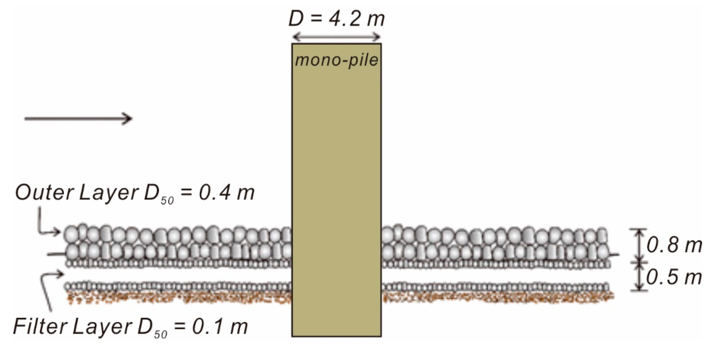
Horns Rev1 is installed at sites of 5–15 m depth 15 km off the western coast of Denmark. The substructure comprises a mono-pile with a diameter of 4.2 m protected by quarry stones that are 0.1–0.5 m in diameter and covered by rock armor that is 0.4 m in diameter [
14]. According to Nielson [
21], smaller stones were planned as the filter layer during the early stages of installation, but many of the smaller stones were washed out even before the outer rock armors were placed. Therefore, to alleviate the loss of the filter stone, the current design was adopted even though it is less effective.
Using sophisticated protection methods such as those in the Horns Rev1 has significant costs associated with the installation’s difficulties. For example, when a bunch of rocks of various sizes is simultaneously dumped out from a barge to reduce the cost, more massive stones land first. Therefore, the scour protection made in this way is quite different from the one planned. Despite these shortcomings, the rock dump installation using a barge is still preferred because it is easy to implement, and the scour protection constructed by the rock dumping can be transformed to a more stable form as can be found in the formation of so-called S berm breakwater since they continuously adapt to its sea state.
Following Nielson [
21] and Nielsen et al. [
14], the available measures to minimize scouring by the horseshoe vortex can be summarized as follows:
First, place fine stones as the filter, and then the filter layer is covered with relatively heavier rock armor, as in the case of the Horns Rev1. However, it should be a prerequisite that the loss of the lighter filter layer stones during construction is resolved.
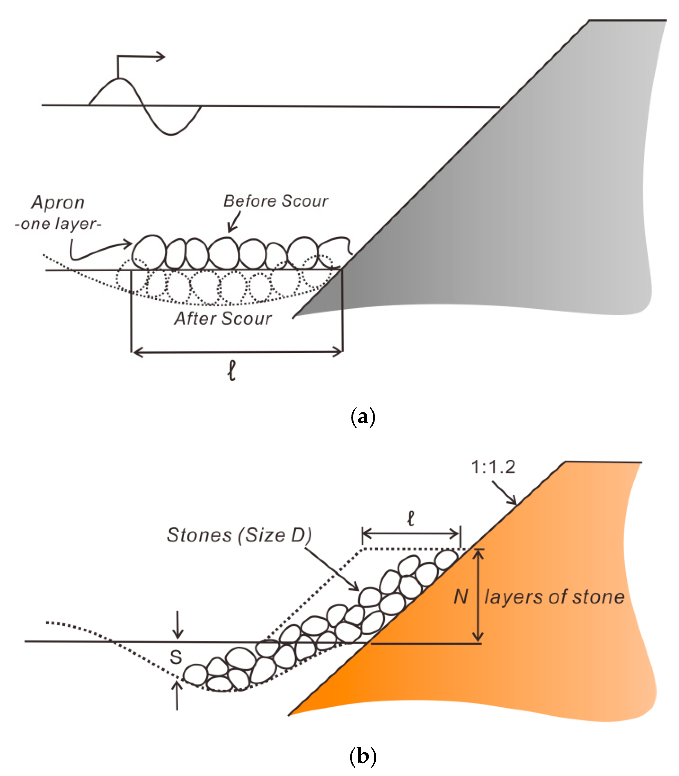
Second, it should be assumed that the sinking of the protection layer is inevitable from the beginning; the scour depth of the protection layer should be predicted at the design stage using the research accomplishments that have been accumulated so far, and additional rocks should be periodically added to the scour protection system.
Third, when the scouring is not predicted to be serious, then not using any protection method could be more economical. The development of an accurate model that predicts the extent of scouring in progress is a prerequisite.
Fourth, limit the deployment of the mono-pile as much as possible. This suggestion is in line with our empirical knowledge that the horseshoe vortex’s strength increases as the diameter of the pile increases. It should be noted that a more energetic horseshoe vortex could be accompanied by severe scouring and the depression of the protection layer.
While the mono-pile is very vulnerable to scouring, as pointed out by Nielson [
21], scouring problems have rarely been reported when a tripod or Quattro-pod jacket is installed in deep water. These tendencies can be interpreted to be induced by the weakened horseshoe vortex because the cross-sectional areas of the tripod or Quattro-pod jackets are smaller than that of the mono-pile. However, we cannot rule out that scouring is weakened due to the flow velocity by currents or waves being slower in deep water.
3.2. Hybrid Mono-Pile’s Scour Control Effects
The strength of horseshoe vortex, boundary layer streaming, and large eddy that is regarded as the primary sediment transport mode is enhanced once the standing waves form due to the reflection from offshore wind farms. Hence, it can be readily envisioned that the standing waves should be minimized for scouring to be mitigated. Therefore, reflected waves should be minimized in order to mitigate sediment transport.
Based on this rationale, we propose a hybrid mono-pile with a turbine mounted on the lower portion of a mono-pile. Once the turbine mounted on hybrid mono-pile encounters waves or current, it smoothly rotates with respect to the pile’s vertical axis. In doing so, a significant portion of incoming wave energy translates to mechanical energy, and as a result, the reflection from the offshore wind farms can be minimized. It is expected that the weakened standing wave in this manner can lead to less sediment transport.
4. Numerical Model
A numerical simulation using FLOW-3D [
17] was carried out to verify the scouring control effects of the hybrid mono-pile proposed in this study. The wave driver in FLOW-3D consists of the Navier–Stokes equation and mass conservation equation. The free surface was tracked using the VOF (volume of fraction) method and the FAVOR (fractional area/volume obstacle representation) method was used to represent the complicated boundaries between the fluid and solid objects [
28]. To visualize the scouring control effects of the hybrid mono-pile, we also trace the saltation and follow the drift of sediment particles initially placed in the vicinity of the mono-pile foundation by using the simplified transport equation described in
Section 4.3, which assumes that the inertia of dispersed sediment is negligible [
17].
4.1. Hydrodynamic Model
Upon introducing the partial area coefficient
and partial volume coefficient
, we can write the mass balance equation, Navier–Stokes equation, and the transport equation for the VOF as follows [
17]:
and
where
,
, and
are a velocity component in the
,
, and
directions, respectively; is a volume of fluid function;
and
are the pressure and the gravitational acceleration, respectively;
is the density;
and
are the diffusion coefficients of
and, respectively;
is the reciprocal of a turbulent Schmidt number; and
is the bottom shear stress.
In Equations (3)–(5), the shear stress
can be written as:
and
In terms of the eddy viscosity coefficient
and a kinematic viscosity coefficient
, the dynamic viscosity coefficient
in Equation (7) through (12) is defined as:
In Equation (13), the varying eddy viscosity coefficient
depends on the characteristic length scale and velocity of the turbulence, and can be defined as:
where
is the turbulence kinetic energy,
is the turbulence dissipation, and
is 0.09 in the
model and 0.85 in the RNG (renormalization-group) model.
In terms of
and the turbulence length scale
,
can be written as:
4.2. Turbulence Model
The variation of the eddy viscosity
within the flow by the local production of turbulence and its ensuing transport and diffusion can be described by the transport equation of the turbulence kinetic energy
and dissipation rate
, which can be written as [
17]:
and
In Equations (16) and (17),
,
, and
, respectively, denote the production of the turbulence energy by the shear stress, the diffusion of the turbulence energy, and the diffusion of the turbulence dissipation, which can be written as:
and
where
and
are the diffusion coefficients of
and
, respectively.
Assuming that the production of the turbulence energy is locally balanced with its dissipation, the boundary conditions for the analysis of the transport equation of
and
is given as:
and
where the shear velocity
is given by the logarithmic velocity distribution, which can be written as:
In Equation (23), denotes the distance from the bottom and is the von Karman’s universal constant.
4.3. Sediment Transport Equation
Derivation of the sediment transport equation used in this study can be summarized as follows. The momentum equation for the sea water and sediment can be written as [
17]:
and
where
and
are the velocity of the fluid and sediments, respectively;
are the density of the sediments;
is the volume fraction of the fluid;
is the body force;
is the drag coefficient; and
is the relative velocity between the dispersed sediment and the fluid.
By subtracting Equation (25) from Equation (24), we can obtain the equation for the relative velocity
, which can be written as:
Even though we can constitute the complete sediment transport models with Equation (26), we simplify Equation (26) to make the computational works more manageable based on our experience showing that the inertia of dispersed sediment is negligible.
Upon introducing these assumptions, Equation (26) can be rewritten as:
To determine the drag force, we need information regarding the volume fraction of the suspended sediments. If suspended sediments are composed of uniform particles and there are
of them in a unit volume, then Equation (27) can be rewritten as:
where
is the volume of a particle,
is the drag coefficient for a single particle moving with velocity of
through the fluid, and
is the volume-weighted average density.
Following the quadratic law for drag force, a drag coefficient
is given by:
where
is a drag coefficient,
is the average sediment particle radius,
is the magnitude of the relative velocity of the sediment, and
is the cross-sectional area of the sediment particle, which is assumed to be spherical in this study.
Using the simplified transport equation of sediments in (28) and the numerically simulated wave field, we can update the drift velocity of sediments using the iterative method at each time step, and then relocate the sediments initially placed in the vicinity of the mono-pile by using the newly updated drift velocity. The final spatial distribution of sediments after enough exposure to waves can distinguish the scouring control effects of the hybrid mono-pile from other scour protection.
5. Numerical Simulation
To investigate the scouring control effect of the hybrid mono-pile proposed in this study, we first numerically simulated wave propagation via a simple mono-pile of D = 4.2 m. Then, we moved on to Quattro-pod, tripod, and hybrid mono-pile [see
Figure 12 and
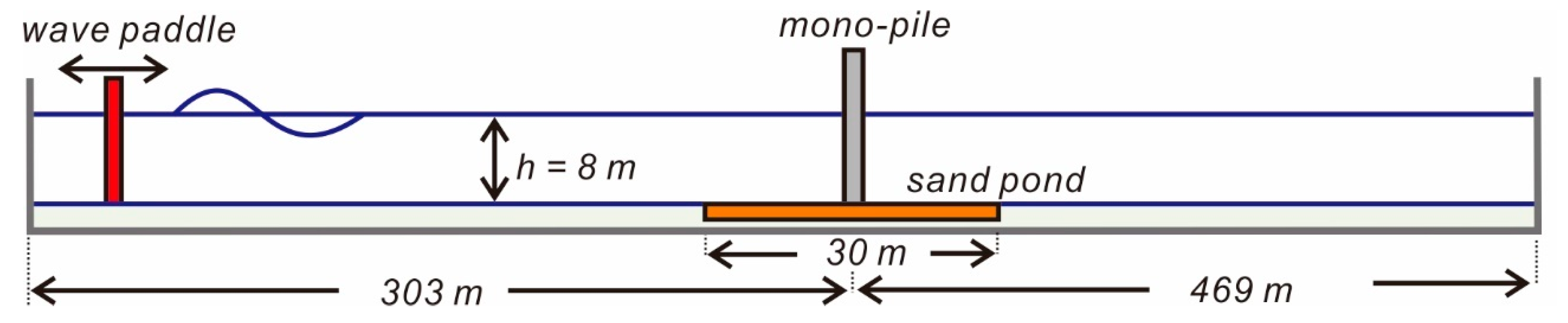
Figure 13]. We used the numerically simulated water surface profile and the run-up height R for the simple mono-pile to verify the numerical model used in this study. A numerical simulation was implemented in a 772 m long and 60 m wide numerical water tank (see
Figure 14). The mono-pile was placed at the center of tank 303 m away from wave paddle to minimize the numerical reflection. The computational domain depicted in
Figure 14 was discretized using a staggered mesh with 622,440 nodes corresponding to 200 per wavelength (L = 102.3 m), which gave enough resolution. Hydrodynamic models described in
Section 4.1 were numerically solved using explicit finite-difference approximation, except for the pressure forces in Equations (3)–(5). Pressure and velocities are coupled implicitly using time-advanced pressure in the Navier–Stokes equation and time-advanced velocities in the mass balance equation. This semi-implicit formulation of the finite difference equation is known to allow for the efficient solution of low speed and incompressible flow problems [
17]. The coupled sets of equations resulting from the semi-implicit formulation mentioned above were solved by an iterative technique known as the successive over-relaxation method [
17]. In doing so, the time step length is automatically adjusted in order to ensure that Courant numbers remain below a threshold of Cr < 0.75 [
17], and the total simulation time is 120 s. Considering the characteristics of swells at the western coast of Korea where a pilot project of offshore wind farms is installed [
4], 3 m high and 12 s long regular waves were generated using a wave paddle and the Biesel transfer function [
29], and the water depth was chosen to be 8 m.
To differentiate the scouring control effect of the hybrid mono-pile from the others, we also trace the suspension and the following drift of 5000 sediment particles initially placed in the 0.2 × 30 × 30 m sand pond (see
Figure 14) around the mono-pile by using the simplified transport equation described in
Section 4.2. The diameter of the silt was 0.212 mm, and the density
was 2500 kg/m
3 [
26].
5.1. Verification
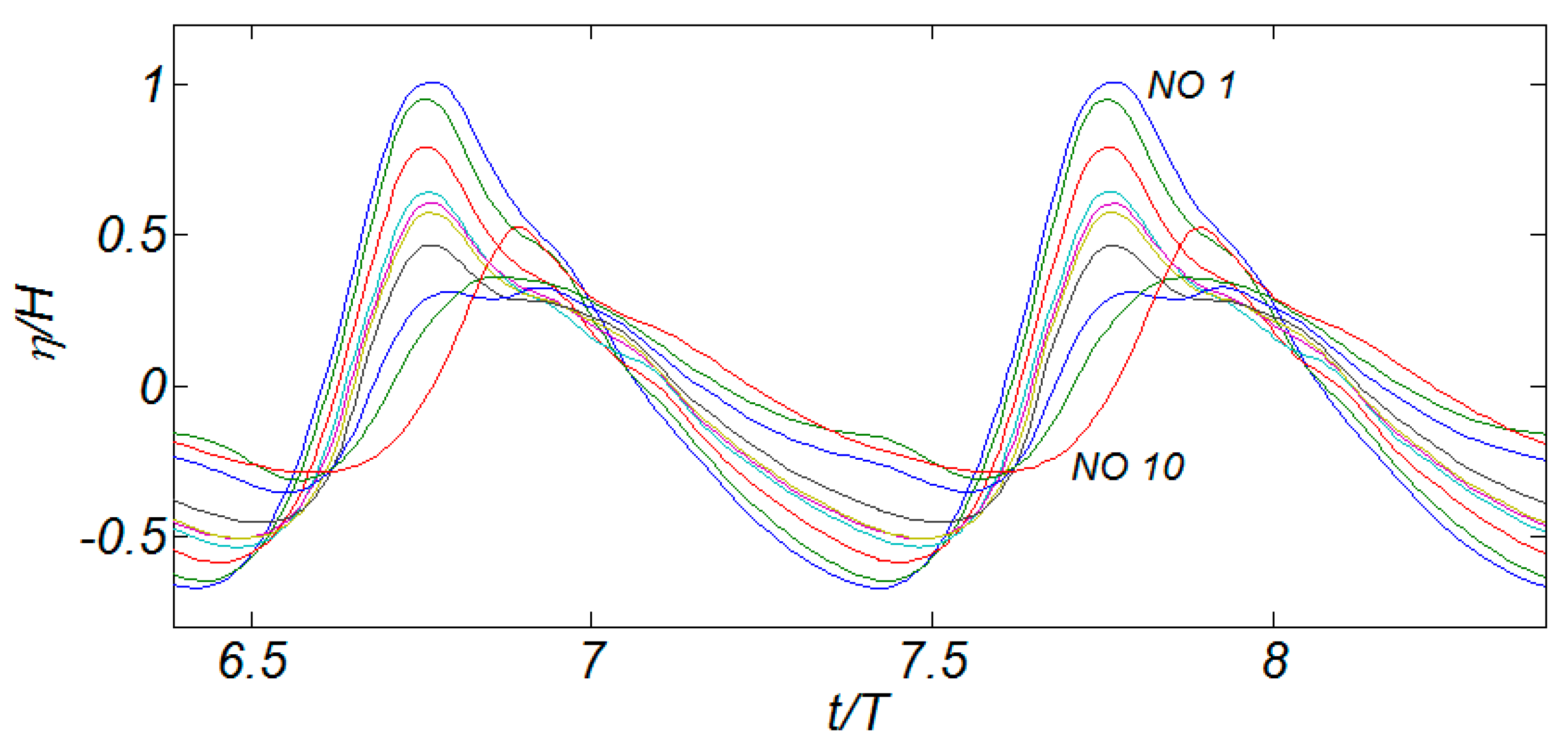
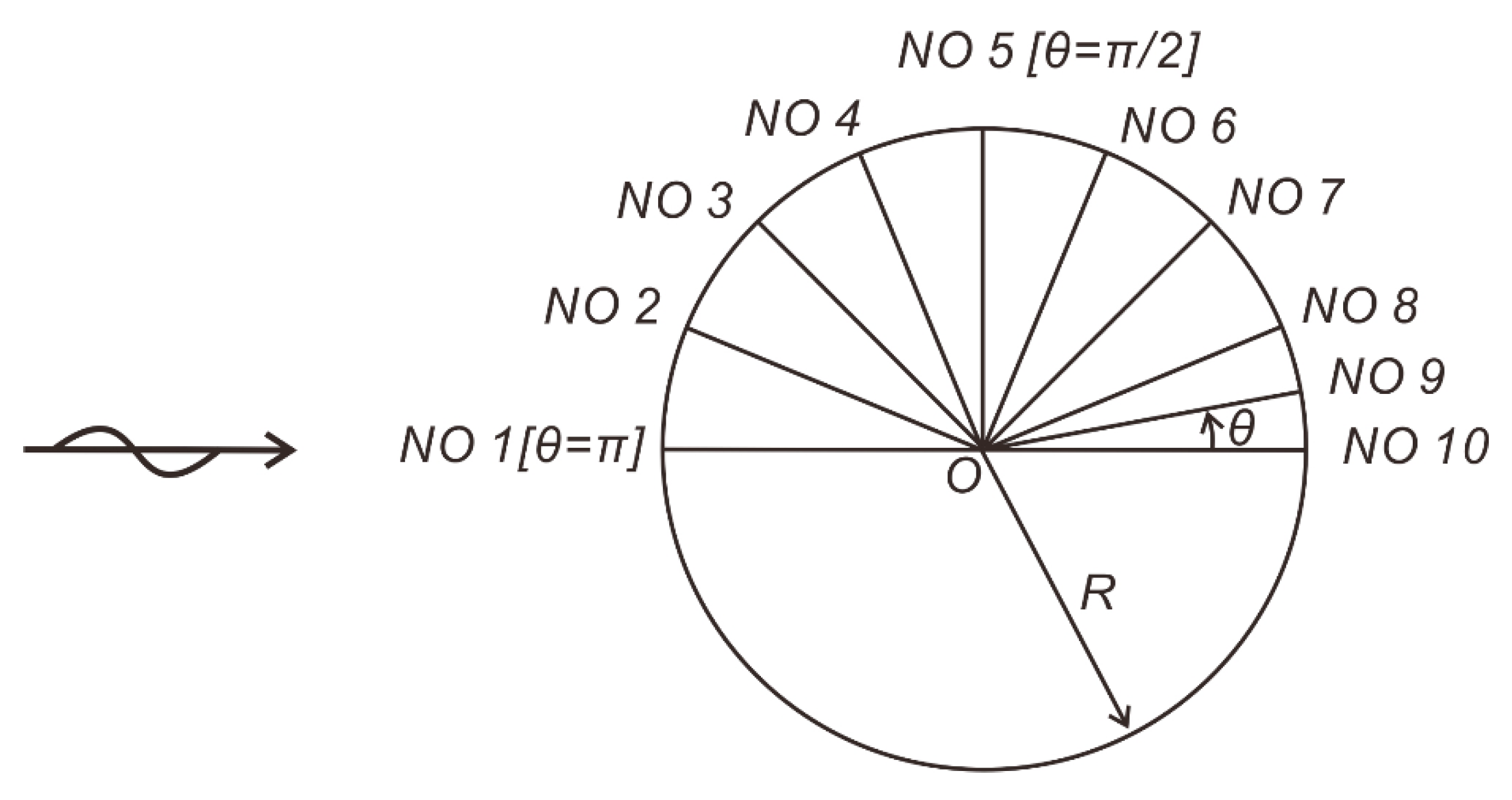
Figure 15 shows a sampled time series of numerically simulated water surface elevations and simulated run-up heights measured at evenly spaced gauges NO 1 through NO 10 [see
Figure 16] around the mono-pile.
Figure 17 shows the numerically simulated run-up height measured at gauges NO 1–NO 10, where the run-up heights measured by Kriebel [
19] are included for the comparison.
It is shown that numerically simulated run-up heights exceed the measured one, and the maximum run-up is twice the incident wave amplitude (H/2) (see
Figure 17). On the other hand, numerically simulated run-up heights at the rear side of the mono-pile are smaller than the measured run-up heights. It is also shown that the location of minimum run-up height shifts more toward the downwave side of the mono-pile than the one measured in the hydraulic model test. However, it should be noted that laboratory experiments by Kriebel [
19] were conducted for nonlinear waves and the slender pile. On the other hand, the numerical results in this study are against swells that are prevailing waves for most of a life cycle of the offshore wind farms at the planning stage in South Korea. Besides, the size of the mono-pile [D/L = 1/24] in this study is relatively large, such that it can barely sneak into the small boy category, and as a result, a separation is not negligible. The rationale for this reasoning can be found in the fact that numerically simulated run-up heights at the rear side of the mono-pile are smaller than the measured run-up heights due to the energy dissipation in the wake of the mono-pile enforced by a separation. Our general perception that a more substantial run-up generally occurs for larger cylinders also supports the reasoning mentioned above. Considering the facts mentioned above, these discrepancies are related to different target sea states rather than a deficiency of the numerical model used in this study.
Other data for the verification frequently referred to in the literature can be found with the analytical solutions based on the linear diffraction theory, which can be written as [
20]:
where
is the water surface elevation,
is the wave height,
is the wave number,
is the angular wave frequency,
is the radius of a mono-pile,
is the Hankel function of the first kind of order
[
30],
for
,
for
,
is the Euler constant, and the prime denotes differentiation with respect to the arguments.
Unfortunately, the agreement of numerical results in this study with the analytical solutions in Equations (30) and (31) is somewhat disappointing. However, the analytical solutions in Equations (30) and (31) are based on potential flow theory, and on the other hand, separation is dominating in this numerical simulation due to the presence of the relatively large mono-pile [
]. Considering that the potential flow theory is valid only when the separation is more negligible than diffraction, these disagreements can be acceptable. Following Kriebel [
19], the run-up heights predicted based on the linear theory are dramatically different from those using nonlinear wave theory, which also supports the reasoning mentioned above.
5.2. Numerical Results
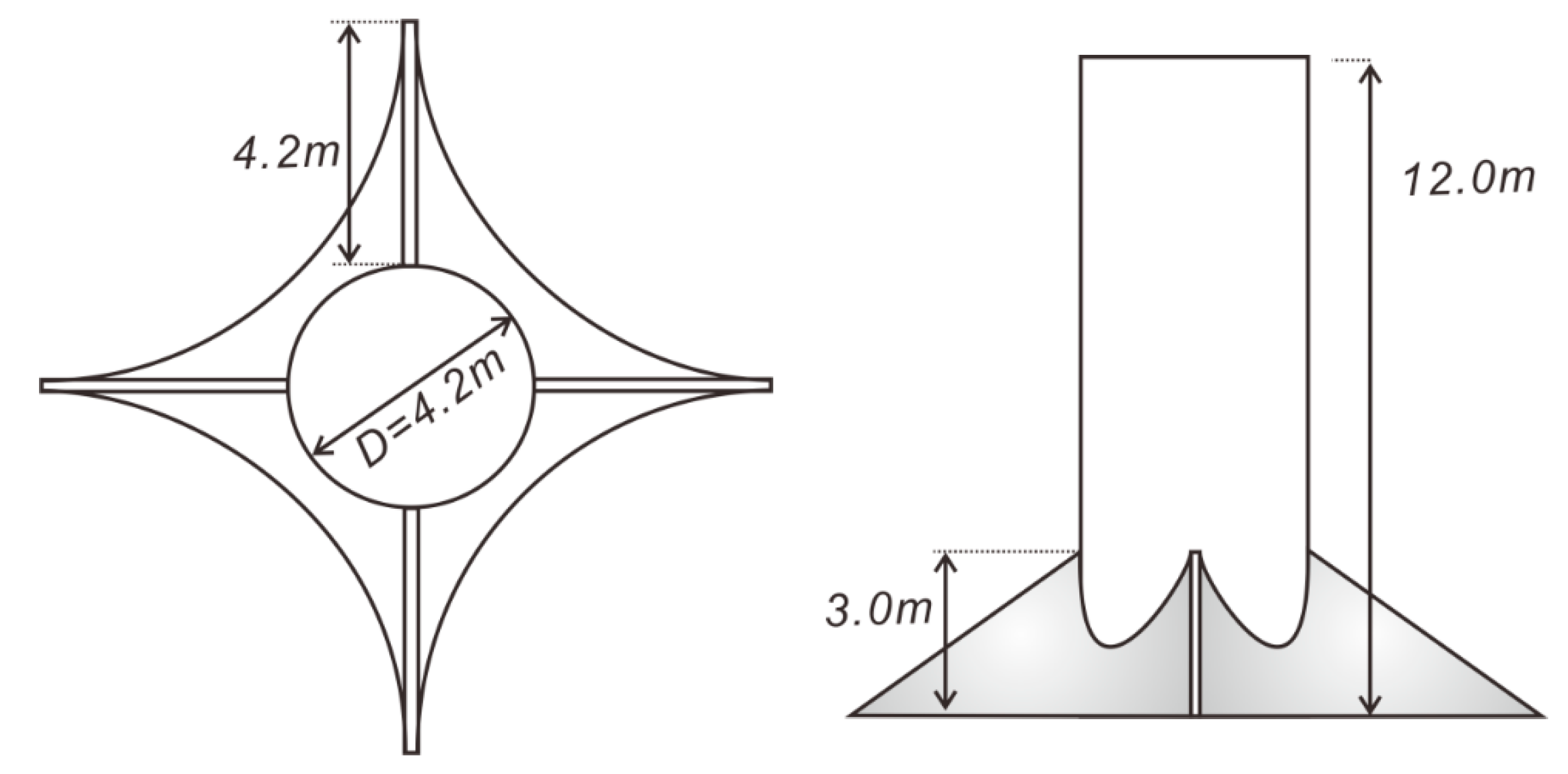
Figure 18 and
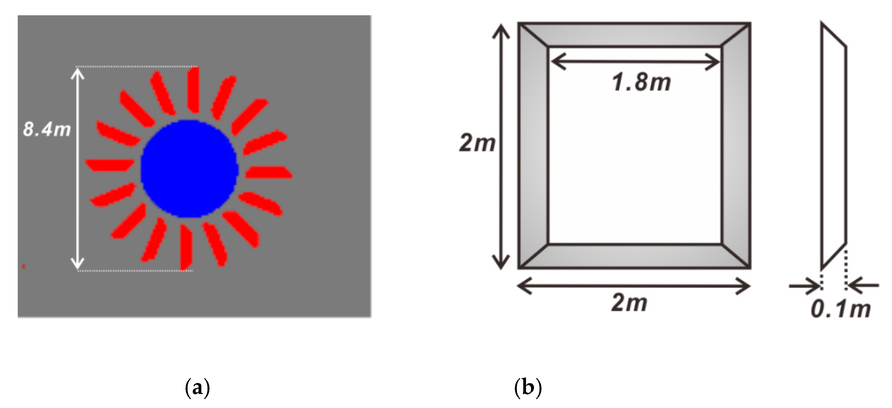
Figure 19 show the Quattro-pod mono-pile dimensions and the hybrid mono-pile used in the numerical simulation.
Figure 20 shows the initial bed morphology in the case of a simple mono-pile. The numerically simulated bed morphology after exposure to waves for 80 s is plotted in
Figure 21. The bottom of a sand pond at the front of the mono-pile is exposed by scouring caused by horseshoe vortex. It is also shown that a small portion of sediments are saltating from a sand pond at the front of the mono-pile by horseshoe vortex and are drifting toward the rear side of the mono-pile due to diffraction. The rationale of this reasoning can be found in the facts that the width of sediment particle layer shrinks at the downwave side of mono-pile due to diffraction, which proceeds toward the downwave side of the mono-pile. These facts clearly show that the simplified transport equation in
Section 4.2 could be an effective tool to distinguish the scouring control effect of the hybrid mono-pile from the others.
In
Figure 22 and
Figure 23, the numerically simulated bed morphologies in the case of the Quattro-pod and tripod mono-pile after exposure to waves for 80 s are plotted. When comparing bed morphology with that of the simple mono-pile, it is shown that the extent of the exposed bottom of a sand pond at the front of the mono-pile is somewhat diminished. On the other hand, a significant portion of sediment particles initially constituting a sand pond at the front of the mono-pile are saltating, being widely dispersed away from the mono-pile and drifted toward mean sea level. Considering the facts mentioned above, in the case of the Quattro-pod, significant scattering occurs even though the scouring is slightly mitigated. However, the extent of the mitigation falls far short of our expectations to develop robust scouring protection for an offshore wind turbine foundation.
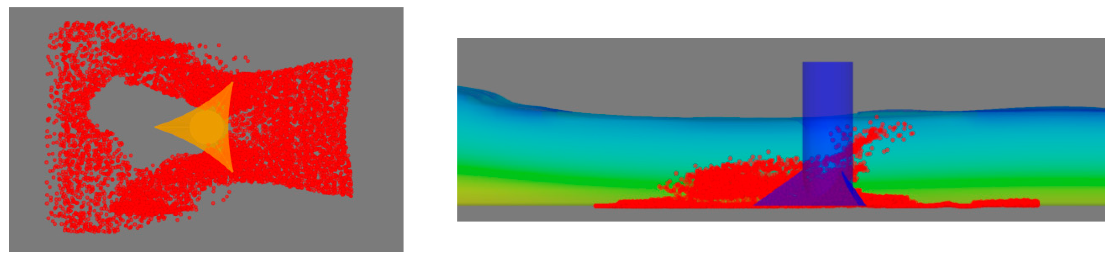
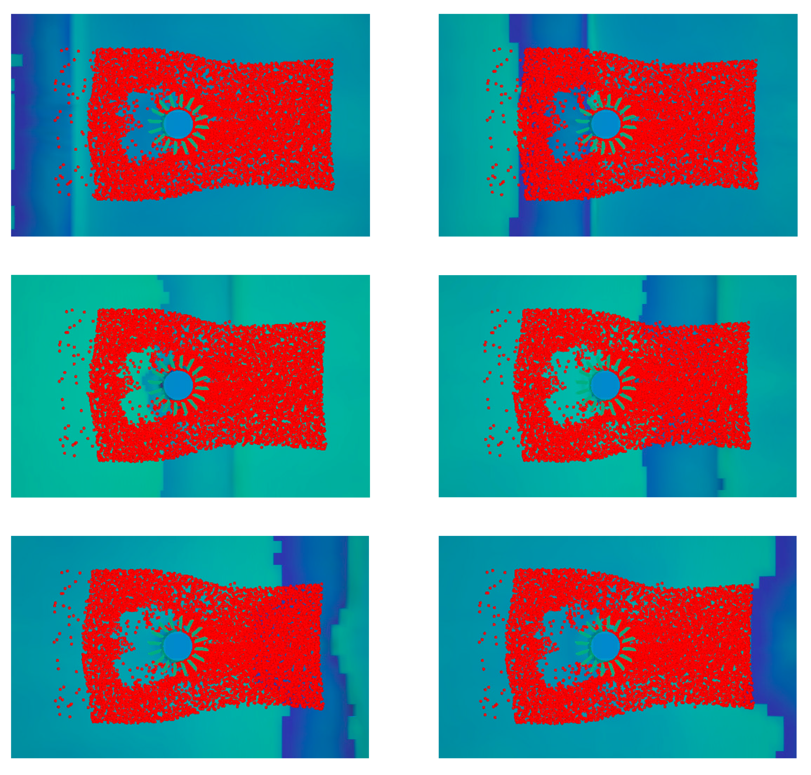
Figure 24 shows the numerically simulated bed morphology in the case of a hybrid mono-pile after exposure to waves for 80 s. It is shown that the extent of the exposed bottom of a sand pond at the front of the mono-pile is dramatically diminished, and a significant portion of the initially deployed silt keeps in touch with the bed. Besides, the overall shape of a layer of sediment particles initially placed at a sand pond in front of the mono-pile undergoes less change than in the cases of the simple mono-pile and Quattro-pod. These features of a hybrid mono-pile indicate that a significant portion of incident wave energy is converted into mechanical energy by the light turbine installed at the toe of the mono-pile, and as a result, an influx of wave energy into the rear side of the mono-pile via diffraction is somewhat weakened. Summarizing the discussion mentioned above, the intended role underlying the shape of the hybrid mono-pile mentioned above is shown to be fulfilled. It is also noted that saltating sediment particles from a sand pond in the vicinity of the mono-pile are considerably reduced (see
Figure 24), indicating that a horseshoe vortex, the primary causative force of scouring, is effectively suppressed by the hybrid mono-pile.
Considering that a significant portion of the initially deployed silt keeps in touch with the bed and a horseshoe vortex, the primary causative force of scouring, is effectively suppressed by the hybrid mono-pile; the scouring reduction effects of a hybrid mono-pile are somewhat verified. In
Figure 25, the sequential snapshots of the bed morphology when the wave crests pass a hybrid mono-pile are plotted. It shows that wave fronts are bending due to diffraction at the downwave side of the mono-pile and that the steady state is reached.
6. Conclusions
Although power generation from offshore wind farms offers immense possibilities, the offshore energy industry’s progress has been hindered due to its high capital requirements compared with other renewable energy sources. There are many capital cost drivers. Among these, the extra cost incurred by poorly designed scour protections can be quickly addressed by developing affordable scour protection that can accomplish its intended purpose by directly alleviating scouring triggers like the horseshoe vortex, a streaming, and a large eddy. To achieve this goal, we first reviewed the scour protection using rocks and hydraulic characteristics near the offshore wind farms. It turns out that most traditional scour protections are very much committed to placing a bunch of rocks in the apron of the substructure of offshore wind farms. Surprisingly, no efforts have been made to develop scouring protections by directly controlling scouring triggers. However, scour protections using armor rock are very vulnerable to wave attack, as can be found in the case of the Horns Rev1, the first large-scale offshore wind farm in the world.
The conclusions drawn upon through this review can be summarized as follows:
The maximum scouring depth in the context of a quasi-equilibrium profile forms the backbone of conventional scour protection. However, considering the random nature of sea state, it is improbable for these conditions to exist around the substructure of offshore wind farms.
The strength of the horseshoe vortex, a boundary layer streaming, and a large eddy, which are regarded as the primary sediment transport mode, is enhanced once the standing waves occur due to the reflection from the offshore wind farms.
Based on this rationale, a hybrid mono-pile with light turbines mounted at its toe is proposed to mitigate the standing waves in front of the pile by diverting the incoming wave energy into mechanical energy, with light turbines rotating with respect to the vertical axis of the pile when it encounters incoming waves or current.
To verify the scouring control effects of the hybrid mono-pile, we first carried out the numerical simulation of the wave propagation via a simple mono-pile, a Quattro-pod, tripod, three-leaf, and hybrid mono-piles. At each time step, we also updated the position of sediment particles initially placed in the vicinity of the mono-pile foundation by using a simplified transport equation due to the saltation and following drift. It was shown that the scouring control effects of the hybrid mono-pile could be effectively differentiated from that of other scour protection by the final pattern of sediment particle distribution after sufficient exposure to waves (80 s).
For the verification of the numerical model used in this study, the numerically simulated water surface profile and the run-up height R for a simple mono-pile were compared with the measured data by Kriebel [
19] in the laboratory experiment. Even though some discrepancies were found, taking into account that target sea states of Kriebel [
19] were different from the ones in this study, and the size of the mono-pile [D/L = 1/24] used in the numerical simulation was relatively large, it was a non-negligible separation that made these discrepancies. The resulting pattern of sediment particle distribution after 80 s showed that a Quattro-pod, tripod, and three-leaf mono-piles slightly mitigated scouring, but the extent of the mitigation fell far short of our expectations to develop a robust scouring protection method for offshore wind farms. It was also shown that a hybrid mono-pile can effectively control scouring because a significant portion of the initially deployed silt was still in touch with the bed. However, it is worthy to note that the scour control effect of a hybrid mono-pile proposed in this study was partially demonstrated against the moderate swells observed at the western coast of Korea and relatively fine sand. As a result, the scour control effect of a hybrid mono-pile is subject to further tests.


