1. Introduction
There have been a number of studies on stationary steam power plant feed water regenerative groups, their exergy and energy efficiency and possible feed water heater optimization. The importance of the feed water temperature at the entrance of the main boilers is related to fuel consumption, as the feed water temperature is lower, fuel consumption to the main boilers is higher and vice versa. The regenerative feed water cycle usually consists of seven or more regenerative heaters, which may be direct or indirect steam heaters. The selected papers were divided into three groups connected by the same problem.
The first group of authors studied the amount of exergy destruction for the regenerative feed water group, which is relatively low compared to the total exergy destruction of the steam power plant. Aljundi [
1] carried out an energy and exergy analysis of the Al-Hussein power plant in Jordan, showing exergy destruction of individual components in the plant. According to the studies, exergy destruction of the feed water heating group, which consists of two low-pressure heaters, a deaerator and two high-pressure heaters, is 0.19% to 0.28% of total exergy destruction. Similarly, Sengupta et al. [
2] analyzed a 210 MW thermal power plant and concluded that the contribution of exergy destruction to the regenerative feed water cycle of all feed water heaters and pumps was the lowest of all major components analyzed in the steam cycle. Comprehensive studies of Turkish power plants were made by Erdem et al. [
3], in which nine thermal power plants were systematically analyzed with their exergy destruction and efficiency rates of the regenerative feed water groups. In that study, the low-pressure feed water heater group contributed 0.02% to 0.46% to the total exergy destruction of the system. The contribution of the high-pressure feed water group to total exergy destruction was in the range of 0.01% to 0.54%. Conventional analyses of the supercritical 200 MW Shahid Montazeri Power Plant in Iran with installed power capacity of 671 MW gave similar results to previous research according to Wang et al. [
4] and Ahmadi and Toghraie [
5].
The second group of selected papers is related to the optimization of feed water regeneration. The aim of the optimization is to decrease the fuel consumption of a stationary power plant. Ataei and Yoo [
6] optimized ΔT of a thermal plant, combining feed water heaters for exergy and the pinch method by the cycle–tempo simulator, succeeding in decreasing fuel consumption by 5.3%. Modeling of a 312 MW thermal plant showed that increasing the feed water at the steam generator inlet reduced fuel consumption in the steam generators. Toledo et al. [
7] conducted an exergy analysis of two 160 MW power plants with six and seven regenerative feed water heaters and the authors concluded that the seventh regenerative feed water heater contributed to decreased specific steam and fuel oil consumption by only 0.5%. Mehrabani et al. [
8] optimized a thermal plant for electricity generation in Shahid Rajaei, India, by introducing a feed water heater and new power unit into the system. They used the genetic algorithm to find the optimal amount of turbine extraction steam. The efficiency of the plant with this approach increased by 5%, however a retrofit investment is required for practical realization of that idea. Espatolero et al. [
9] optimized a 770 MWe power plant with the addition of one new LP heater, two drain pumps and an indirect flue gas heat recovery system with double-stage integration in the cycle, increasing plant efficiency by 0.7%.
The third group of selected papers is related to research combining the feed water regenerative cycle with solar field collectors and showed the following results. Adibhatla and Kaushik [
10] tried to combine feed water regenerative groups to incorporate solar-aided feed water heating for a 500 MWe thermal power plant, but exergy efficiency of such a setup was lower than the classical Rankine regenerative cycle that is associated with exergy destruction in the collector–receiver system. Another study was carried out by Ahmadi et al. [
11], integrating a solar field instead of the feed regeneration group [
11]. It gained benefits by replacing high-pressure feed water preheaters with a solar farm, resulting in increased energy and exergy efficiencies of the power plant by 18.3%. Following a similar idea, Mohammadi et al. [
12] incorporated a solar heating collector upgraded with a thermal storage system, as that system can be used at night, resulting in increased net generated power by 8.14%. The main problem with solar field heat generation is high capital cost, which is a problem with such concepts, but it saves fuel and reduces pollution [
13]. The payback time, which varies according to the size and position of the plant, can be about 4.5–5.5 years, according to Bakos and Tsechelidou [
14] or 5.13–6.21 years if thermal storage is included in the system [
15].
A marine plan analysis carried out by Koroglu and Sogut [
16] concluded that a feed water heater’s efficiency could be improved externally only as a result of improvements to other components, such as turbine, boiler, condenser and pump equipment. As a marine steam propulsion plant is slightly different compared to a stationary plant, the return of condensate to the feed water system has not yet been evaluated in the scientific literature. Taking this into consideration, a case study of a specific condensate system of a 30 MW marine steam plant is explained and elaborated in this paper. The main difference between the marine condensate system and a stationary steam plant is the condensate cycle loop, which is divided into two groups and is joined together in the atmospheric drain tank. The temperature of the returned condensate in the atmospheric drain tank affects the temperature of the feed water before entering the deaerator as these two streams join before it. As the deaerator is a direct feed water heater, lower feed water temperature will require more steam consumption to heat the feed water to the saturated temperature, which results in higher fuel consumption of the marine power plant.
The paper is divided into two parts. The first part describes the calculation of energy and exergy efficiency of joining condensate water in the atmospheric drain tank as the direct heater, where stream flows from the condensate system are measured. The second part describes the optimization of the obtained exergy results with the adjusted stream flow temperatures in order to improve the efficiency of the joined streams in the direct heater, i.e., the atmospheric drain tank. As the efficiency of the atmospheric drain tank has an impact on the main feed water line temperature before the deaerator since it is mixed with the same. It is important to maintain it at the optimized level. The optimized temperature will save fuel consumption of the plant, which is the motivation for this work.
2. Feed Water and Steam Condensate System
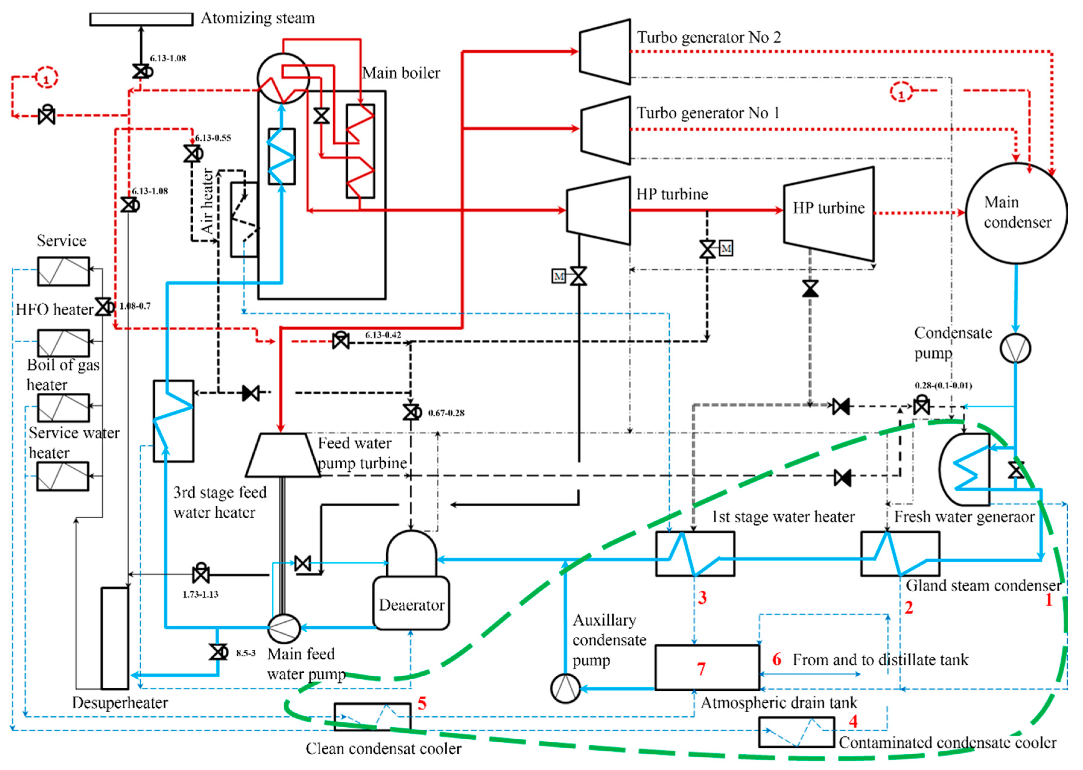
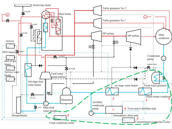
A steam turbine vessel’s main condensate system, as part of the closed feed water cycle, allots circulating feed water from the main condenser to the main boilers. Condensed water is taken from the main condenser and passed through the fresh water generator, gland steam condenser and first-stage heater and goes towards the deaerator, main feed water pump and third-stage feed water heater before entering the main boilers (
Figure 1). In that feed water line, all heaters are indirect heaters and the deaerator is a direct heater.
During that process, feed water is taken from the main condenser, where the steam outlet from the main turbine and turbo generators condenses at saturated steam pressure. The temperature of the condensate water depends on the vacuum and seawater cooling temperature and varies from 30 to 40 °C. Condensed water is taken from the main condenser well and passes a group of heaters, whereupon it comes to the main boilers preheated to about 140 °C in the liquid state due to the high pressure of the main boiler water drum, which is maintained at about 6.3 MPa. Section heaters of the mentioned allotment are divided into extraction steam heaters or regenerative heaters and non-extraction or system heaters. Regenerative steam heaters get steam from the main propulsion turbine, which includes first-stage feed water heater, deaerator and third-stage feed water heater, where the fresh water generator, when it is heated from the main turbine extraction, acts as a regenerative feed water heater; otherwise it is a system feed water heater that consumes steam from the system. The condensate section is drawn with a blue line in
Figure 1.
Condensate from the service system (5 in
Figure 1), fresh water generator (1), gland condenser cooler (2) and first-stage heater (3) collects in an atmospheric drain tank, where it is mixed with distillate makeup water (6) taken from the distillate tanks. Distillate water makes up all water losses in the system, which, if there are no steam leaks, mainly must be refilled to the system due to the atomizing steam and soot blow losses inside the main boilers. Condensate from the service line is drawn with a dashed blue line in
Figure 1. In the marine steam turbine plant, the service group is connected to the main propulsion plant system via the atmospheric drain tank. Service steam is used for the various heavy fuel oil (HFO) heaters, boil off gas (BOG) heaters and accommodation service. BOG heaters are used for heating and vaporizing liquefied natural gas (LNG), which is taken from the cargo tank when there is not enough methane vapor from the tank. The amount of steam for the BOG heaters is controlled by the cargo and boiler management system which controls the cargo tank pressure, as described in [
17].
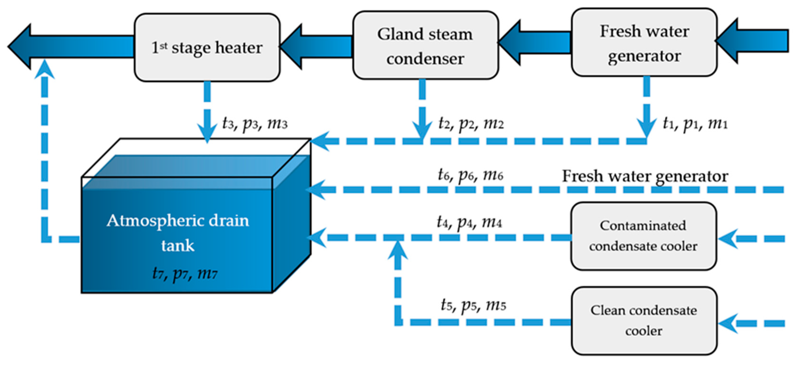
The atmospheric drain tank is the collecting node for both contaminated condensate (4) and clean condensate (5) (
Figure 2). These two condensate streams arise from the auxiliary steam system, while contaminated condensate is part of various HFO and lube oil heaters. In order to prevent contamination of the system, condensate from these heaters first passes through analyzing and treating units, which set off an alarm of contaminant is detected in the water, such as fuel oil or lube oil, that may destroy the main boiler tubes by depositing into it, causing local overheating [
18].
The clean condensate inlet from the system, which is not in contact with hydrocarbon substances, also enters the atmospheric drain tank, but directly without monitoring and is mixed with the monitored contaminated condensate. Both streams, along with the distillate water stream in the atmospheric drain tank, are again returned back to the system.
As the steam propulsion plant system is dynamic, an additional role of the atmospheric drain tank is to amortize excess and make up the feed water in the system with the spilled feed water back to the distillate tanks or extract it from the distillate tanks again to the system with a change of the plant load. Basic LNG carrier power propulsion plant characteristics for maximal power, vacuum and flow are given in
Table 1 [
19,
20].
5. Energy and Exergy Analysis Results
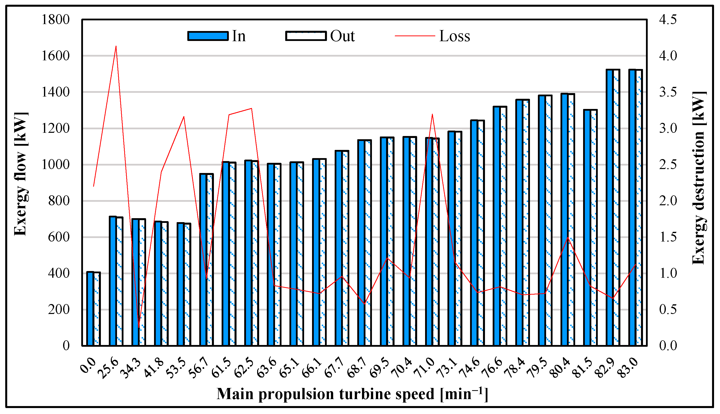
Atmospheric drain tank energy flow streams show that at lower loads of the main propulsion turbine, total energy loss in the atmospheric drain tank is higher compared to higher load ranges, as seen in
Figure 3. The energy loss in the maneuvering range is the result of an accumulating function of the drain tank, where load changes in the system are compensated by adding feed water to the tank. After passing the maneuvering range of the steam propulsion plant, 0.0 to 53.5 min
−1 and reaching a ship speed of about 13 knots, the main sea water circulating pumps are stopped and cooling of the main condenser is taken over by the scoop system, which collects sea water according to the ship’s speed.
The opening of the scoop system corresponds to about 61.5 min
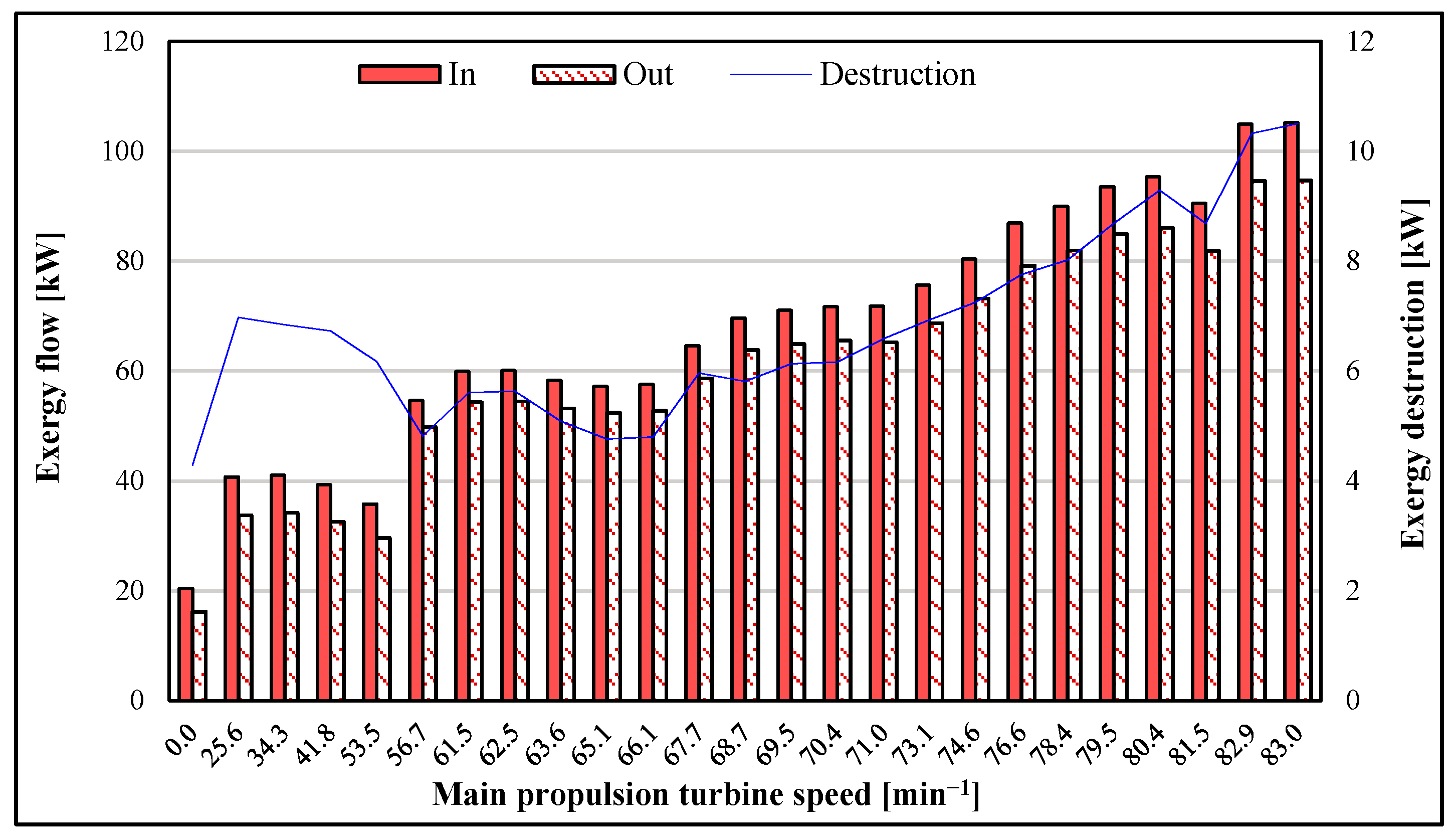
−1, after which energy losses become lower and are distributed more equally through the upper range of the load range. Exergy flow losses of the atmospheric drain tank have an opposite trend to energy losses and increase even with the increased main propulsion turbine load (
Figure 4). Exergy destruction amplitude is about 10 kW at the highest load, which is almost double compared to energy losses. The increment of exergy destruction with increased load is typical for disturbances in the system that may be connected to some equipment, under capacitance or similar construction design failure. The observed shortcoming may be improved by optimizing the respective component flow streams. The moment of decreasing exergy destruction trend at higher loads is at 1.5 min
−1, where extraction of steam from the high-pressure turbine begins. The extracted steam is used for ship services. This moment obviously acts positively on the exergy destruction of the atmospheric drain tank.
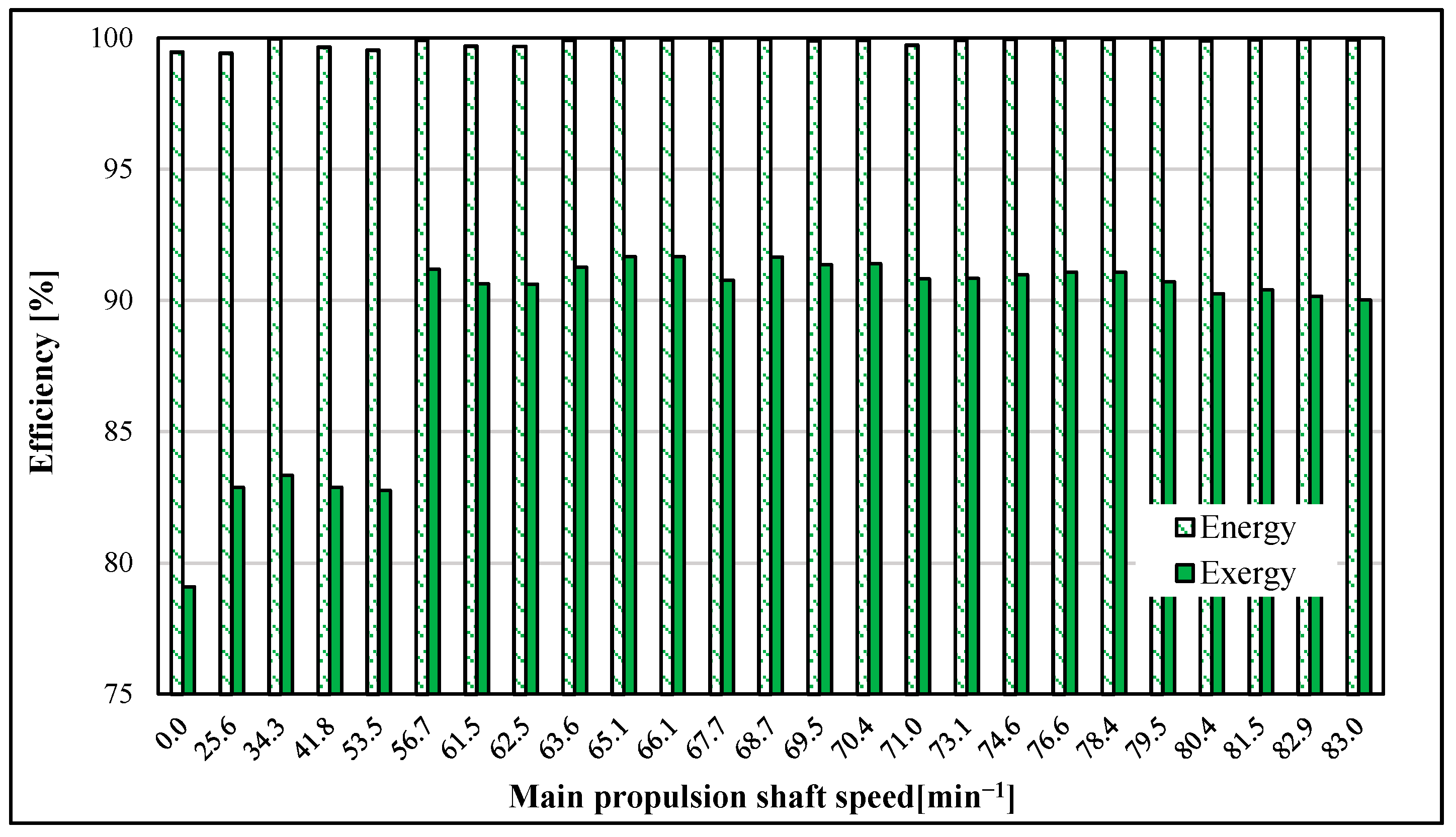
A comparison of energy and exergy efficiency is given in
Figure 5. Energy efficiency of the joined streams in the atmospheric drain tank was very high, above 98% at all measured ranges. On the other side, results of exergy analysis indicate that exergy efficiency of the joined streams inside the atmospheric drain tank was somewhat worse when the main propulsion turbine was not running and throughout the maneuvering range. The exergy efficiency of the joined streams in the port was below 80% and after passing the maneuvers zone it stabilized to about 90%.
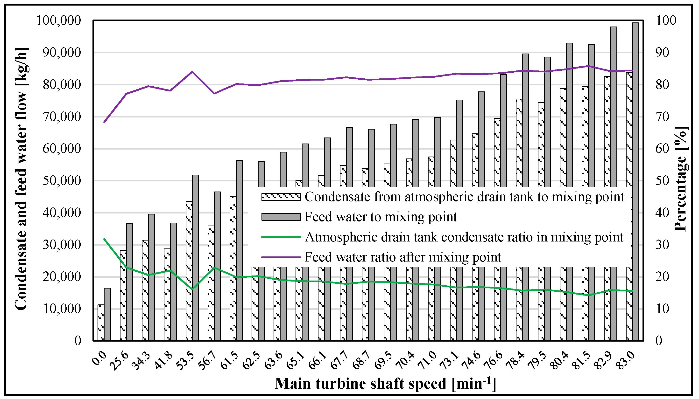
Figure 6 shows the condensate mass share from the atmospheric drain tank versus the amount of feed water passing the first-stage heater at their mixing point. When a ship is alongside for a cargo operation, part of the condensate coming from the drain tank to the common feed water line is over 30%, while when maneuvering the vessel and with further increased main propulsion turbine load, that ratio drops down to about 15%. Accordingly, the temperature at atmospheric condenser outlet has an influence on the feed water temperature after the mixing point of the two feed water lines. By decreasing the feed water temperature after the mixing point, deaerator losses are increased, as it will be required to lead more steam onto the deaerator in order to bring feed water to saturation temperature, which is required in order to release various dissolved gasses from the feed water [
39].
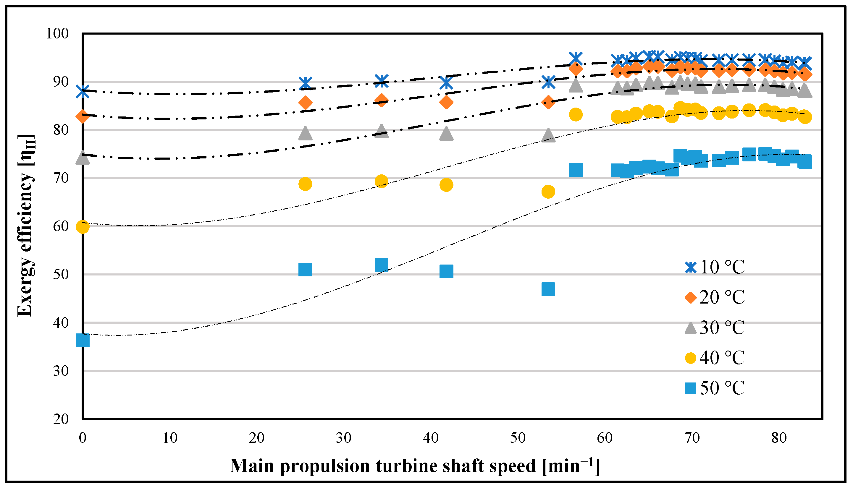
Exergy efficiency variation with changing ambient temperature is given in
Figure 7 and was assessed according to the recommendations in [
40,
41]. This measurement gives a good outlook on the effect of ambient temperature on exergy efficiency in various sailing destinations where the LNG carrier is operating. The selected range of exergy variation is surrounding temperature from 10 to 50 °C. The reference temperature is 25 °C and 0.1 MPa. The results of exergy efficiency variation show that it decreases with rising temperature, especially between 40 and 50 °C. Degradation of exergy efficiency is more conspicuous in port. In the upper loads of the steam plant, the difference in exergy efficiency is smaller. Such high discrepancy in exergy efficiency is mainly caused by the condensate temperature from the fresh water generator. The spray water for cooling the steam remains open even when the fresh water generator is not producing the water in the port and lower loads. A cold stream of water reduces the temperature in the atmospheric tank and decreases exergy efficiency.
6. Mathematical Formulation of Atmospheric Drain Tank Optimization Problem
As an optimizing tool, a fourth-degree polynomial with one variable is used to calculate specific exergy according to data taken from [
42] to achieve more accurate optimization results. The common polynomial of
kth order according to [
43,
44] is:
The sum of residue squares when approximated by value
yi of polynomial
P(
xi),
i = 1, …,
n is:
A partial differential of Equation (15) yields the following set of equations for extrema:
The previous system of equations is equivalent to the following:
The same in matrix notation reads as:
The matrix system in (21) is equivalent to the following system with a Vandermonde matrix [
45]:
Let the Vandermonde matrix from (22) be denoted by
X and the vector with the coefficients
ai,
i = 0, …,
k be denoted by
a. The solution to (21) and (22) can be found by multiplying system (23) by the inverse of
X:
The procedure described by (14)–(23) was used on data taken from [
42], which yielded polynomials for specific exergy at various temperatures and pressures. The polynomials, as a function of temperature at given pressure
f (
t,
p), are listed below; a complete list of the used polynomials is given in the appendix.
Atmospheric tank specific exergy outlet and distillate water inlet to the tank:
Contaminated condensate cooler specific exergy outlet and clean condensate cooler outlet:
The optimization function is used to achieve maximum exergy efficiency of the joined exergy streams in the atmospheric drain tank by the calculated exergy fourth-degree polynomial functions:
The optimization variables are:
Contaminated condensate cooler temperature outlet t4;
Clean condensate cooler temperature outlet t5;
Distillate temperature t6.
Fixed conditions are:
Exergy of stream inlet to atmospheric drain tank from fresh water generator ex1;
Contaminated condensate cooler temperature outlet t4;
Exergy of stream inlet to atmospheric drain tank from gland steam condenser ex2;
Exergy of stream inlet to atmospheric drain tank from first-stage feed water heater ex3;
Mass flow inlet to atmospheric drain tank from m1 to m6 are fixed;
Pressure from p1 to p6 is fixed.
With following conditions:
Conservation of mass flow:
t7 is determined by partial temperature ratios of all mass flow participants:
Under given constraints:
Contaminated condensate cooler temperature outlet:
Clean condensate cooler temperature outlet:
Distillate water temperature from the tank:
Energy efficiency of joining streams to atmospheric drain tank:
Optimization was performed with the gradient reduced gradient method (GRG) from Excel’s solver analysis packet [
46]. The options were adjusted as follows:
7. Optimization Results
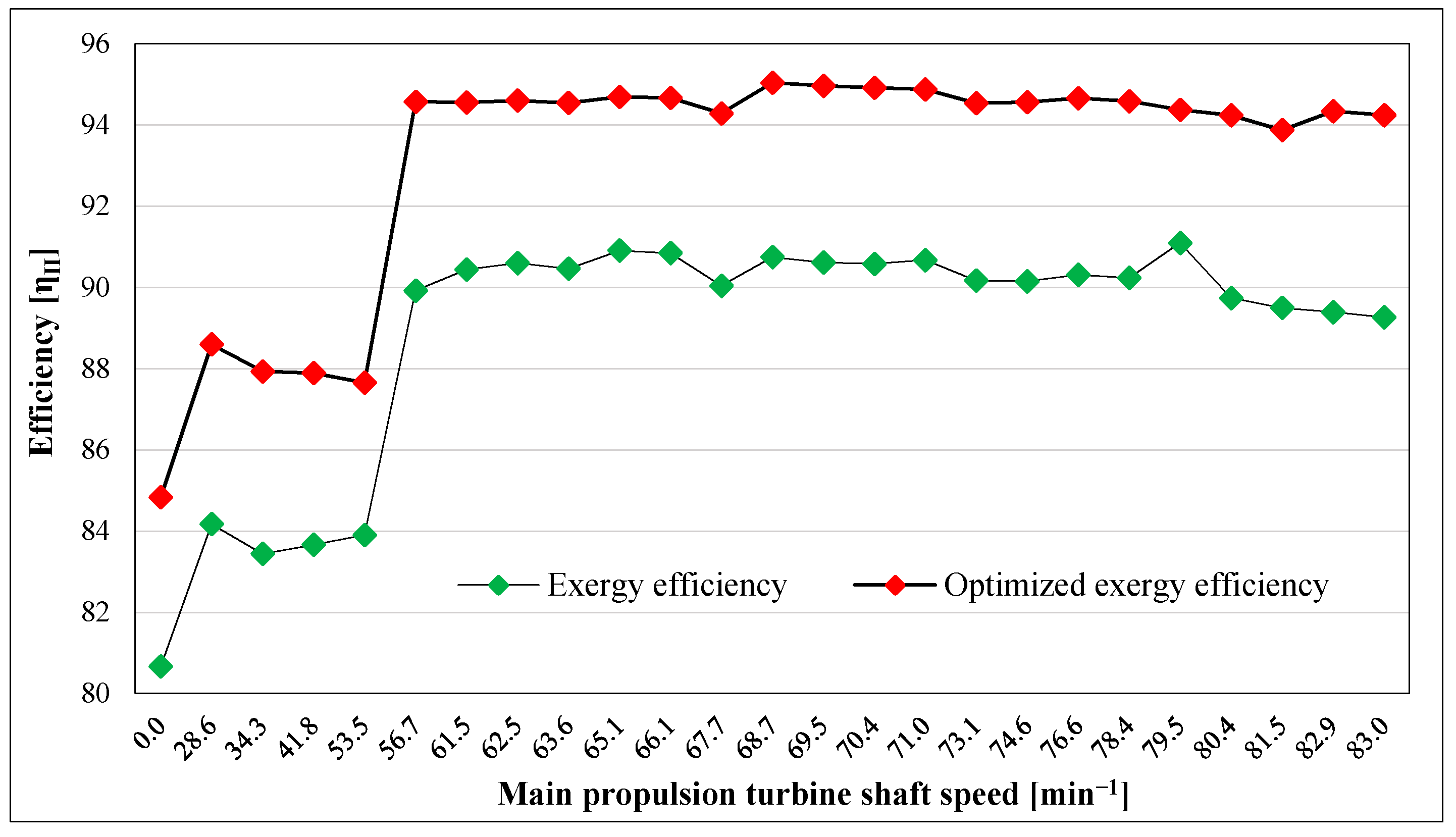
The optimized exergy efficiency of the atmospheric drain tank joining streams is given in
Figure 8. The aim of optimization is to achieve the maximum exergy efficiency of the joined exergy streams in the drain tank by calculated exergy fourth-degree polynomial functions. As per the results, better exergy efficiency of the atmospheric drain tank joining streams was achieved in all running ranges of the marine steam propulsion plant. At the maneuvering load of the main propulsion turbine, exergy efficiency increased by about 5%. From 56.7 to 83 min
−1 at the main propulsion shaft, exergy efficiency increased by 3% to 4%.
Optimization results indicate that maintaining distillate temperature at the atmospheric drain tank inlet as high as possible is required (
Appendix A,
Table A4). Maintaining a higher distillate temperature requires consuming distillate from the tank where it is stored from the fresh water generator, as its temperature from the fresh water generator is ~45 °C. This action is avoided in the operation of the marine steam plant due to safety, which means that if the salinity of the distillate water at the fresh water generator increases and the salinity sensor fails, such higher-salinity distillate will be mixed with the distillate in the tank and could cause damage to the main boiler pipes. According to the Unitor guide [
47], for medium-pressure boilers, 3–6 MPa chloride content should be less than 30 ppm. The main boiler maker has even stiffer standards; according to Mitsubishi chloride content should be 20 ppm or less [
48]. Normal chloride content when the fresh water generator is producing distillate is below 5 ppm. However, a permanent monitoring system is installed for the boiler water onboard the ship, and there is no harm if boiler water is consumed from the distilled tank, where fresh water is coming directly from the fresh water generator. The recommendation is that this method become the norm.
The steam pressure of the contaminated service system is 0.7 MPa and clean condensate system 1 MPa. The ideal temperature of the contaminated condensate steam is 126 °C and clean condensate system 143 °C after phase change. If the service system is overloaded temperatures are lower due to additional cooling of the steam in the heat exchangers. As the temperature of contaminated and clean condensate outlet flow streams is still higher it should not be cooled at 70 °C but should be maintained at a higher temperature of about 90 °C after cooler. Maintaining the higher temperature increase exergy efficiency of the atmospheric drain tank as a direct heater. The control of the condensate temperature after the cooler is simply achieved by throttling the cooling water inlet to the condensate coolers.
8. Conclusions
According to an exergy analysis in port and at lower loads, it is clear that desuperheating water at the fresh water generator line, which comes from the main condenser feed water line, should be kept closed as fresh water generator is not in service and there is no steam for cooling down the fresh water generator. That part of the feed water is led back to the atmospheric drain tank and cools down the condensate inside the tank.
Optimized parameters clearly show that distillate water should be filled in the atmospheric drain tank from the tank that is in use, as optimized temperature is kept all the way at the upper constraint of 40 °C.
Clean and contaminated condensate temperature follow each other under the proposed optimization setup without regard to condensate mass flow, and they should be kept at the condenser outlet at 90 °C, which can be done simply by throttling the cooling water amount to the condensers or fixing an automatic control valve for temperature control at the condenser outlet.
The benefit of such a procedure is that condensate water will enter into the main feed water line with higher exergy potential, which will increase the efficiency of the power plant and save on fuel consumption. Optimizing the atmospheric condenser drain tank is the first step in the process of optimizing the whole feed water section, which will require investigating the interactions of optimized components in real application conditions, which is planned for future research work.


