1. Introduction
The shipping industry is one of the oldest industries that acts as a backbone of global trade and economy. Today, over 53,000 merchant ships conduct international trade with an economic value of 1.3 trillion USD, which includes general cargo, oil tankers, chemical tankers, passengers, and liquefied natural gas [
1]. All such ships must undergo a series of routine repair tasks while docking in a shipyard in order to maintain a smooth and foul free operation. Most of the major repairing tasks will be conducted during the dry-dock period, such as paint-stripping, inspection, painting, etc. Among those, inspection tasks are always seen as highly labor intense, and hazardous to human operators when accessing constrained narrow spaces. Ship owners diverted their interest in using robotic solutions in order to reduce the amount of risk and drawbacks in the manual inspection process, which eventually opened a new market for robotics products. After witnessing the market demand, various aspects of ship hull inspection robots, including mechanism design, human interaction, and autonomy, have been researched in depth over the last two decades.
So far there have been numerous proposed mechanisms that target inspection tasks with smooth and robust vertical locomotion. One such robot can be seen in [
2], where the robot is composed of a rigid PVC body and four equal standard units, each including a combination of locomotion and adhesion systems. Each unit has a pair of wheels, rubber and magnetic to locomote and an actuated structure with a permanent magnet and two inductive sensors (one for detecting the high position and one for the low position) for making adhesion adjustment to the vertical surface. In addition, each standard unit of the two rear systems has an auto-levelling structure which includes a mechanism with a sliding guide and compensated through a spring for the event of irregulated and curved surfaces. In [
3], the robot is made up of a body frame with two DC servo motors: one motor for driving the robot forward and backward and the other motor for the purpose of steering and a differential gear box. The two smaller wheels are coupled with the steering DC motor at the front and the two larger wheels are assembled with the driving DC motor at the back. At the base of the robot body frame, twelve quantities of 30 × 30 × 5 permanent rare earth magnets are glued to support a clamping force of 110 N to the operating surface with the air gap of 6 mm between the robot frame and the surface. In another robot [
4], it consists of the body frame with the mechanisms of permanent magnetic adhesion, tracked locomotion, and driving. Each track contains a roller chain in which 66 permanent magnetic units are arranged. The robot uses a small and lightweight AC servo motor as its power producer. A tank is designed on the rear support bracket for the sprocket adjustment and in order to climb over the uneven surface, an inclination angle of 45 degree is made between the driving sprocket and tensioning sprocket. In [
5], the robot is implemented with differential drive locomotion mechanism while using two wheels that were equipped with 50 neodymium magnets each and the wheels are driven by two DC gear motors. Every pair of the magnets are made to be in opposite magnetic field orientation in order to achieve iincreased adhesive power. The robot also has an elastic tail on which a third neodymium permanent magnet is attached in order to maintain the stability of the robot on the wall.
In every robot, a reliable human robot interaction is required to achieve the stable robot function. Different human robot interactions can be found in the existing literature that are related to the hull inspection. In [
6], analogue to digital AVR microcontroller based embedded system is used to operate the motors and sensors and obtain the serial transmission of the analogue data for making data analysis. The onboard control module can be accessed with Bluetooth wireless communication system. For the robot in [
7], the control system consists of two main units, console and mobile platform. The mobile platform is equipped with Arduino Mega 2560 microcontroller board to drive the motors and transmitter-receiver modules and Raspberry Pi3-Model B single board computer to connect with camera for video stream. For the purpose of interacting with humans, the console is equipped with joysticks, analog potentiometer, and switches to control the input parameter and an iPad is used as a display. In the oil tank inspection robot [
8], the control system includes the embedded computer system, the vision system, the motor driver system, the communication system and the sensing system, and even web based teleoperation for wireless robot commanding can be provided. In the control system of [
9], the Atmel ATmega328p microcontroller is used to interface with motors and sensors, an Android phone is utilized to control the robot through the Bluetooth wireless communication and LCD screen is used to get the inspection data from the wireless camera mounted on the robot.
Regarding autonomy, there is no such autonomous hull inspection robots with vertical wall climbing mechanisms for the drydocking purpose in the shipyards. On the other hand, there are many researches regarding Automatic Underwater Vehicles (AUVs) for the underwater inspection works during the ship operations or wet docking. In one of AUVs [
10], it describes the implementation of a simultaneous localization and mapping (SLAM) by using forward-looking sonar, FLS data. The algorithm named ESEIF is applied to accomplish the SLAM based upon features manually selected with FLS images. The results could demonstrate the capabilities of efficient mapping an underwater ship hull, but it is not real time SLAM and cannot cover the whole coverage. In [
11], the robot has uniqueness due to using omnidirectional wheels while making capturing and mapping. Even though the robot could make the autonomous inspection on underwater hull, the cost of implementing it is so much expensive. In another research work [
12], it reports real time SLAM based localization system for underwater ship hull inspection purpose. The first-generation extended Kalman filter (EKF) SLAM system is developed using stereo camera and then landmarked tracking techniques are employed. Nevertheless, the observable ship hull size is limited according to the computational complexity of the EKF and the system needs more development in order to be a promising instrument.
By evaluating the existing literatures of ship hull inspection robot, it is proven that there is a huge gap in developing autonomous systems for dry docking conditions. Furthermore, most existing robots cannot achieve non-destructive testing that means evaluating the properties of a material without damaging the part, in this case, for measuring the thickness of steel plates autonomously. To this end, we are proposing a novel robot, named Sparrow, in this paper, which is capable of navigating autonomously on the vertical metal surface and could perform metal thickness inspection. The major contribution in the proposed robotic system is the development of autonomous navigation along with the ultrasonic thickness measurement system and its relevant mechanical design. Such an ability has never been demonstrated in the existing magnetic climbing robot for an inspection task. The major challenges that were encountered during the development of our Sparrow robot were its magnetic adhesion mechanism, the integration of inspection modules, autonomous operation, and translating the theoretical design into a physical system. This paper summarizes all of these aspects and concludes with experimental results that validate the autonomous inspection capability on three different metal plate varying with thickness. The proposed Sparrow robot represents an initial design towards the fully autonomous climbing robot that can perform multi inspection task on a ship hull during dry docking.
The rest of the paper is organized, as follows. The mechanical design of the robot will be described in
Section 2 and
Section 3 will discuss about robot platform description. In
Section 4, control design and autonomous feature will be shown and
Section 5 will describe the experiments and results. The discussion will be presented in
Section 6 and, finally, conclusion and future work will be represented in
Section 7.
2. Mechanical Design
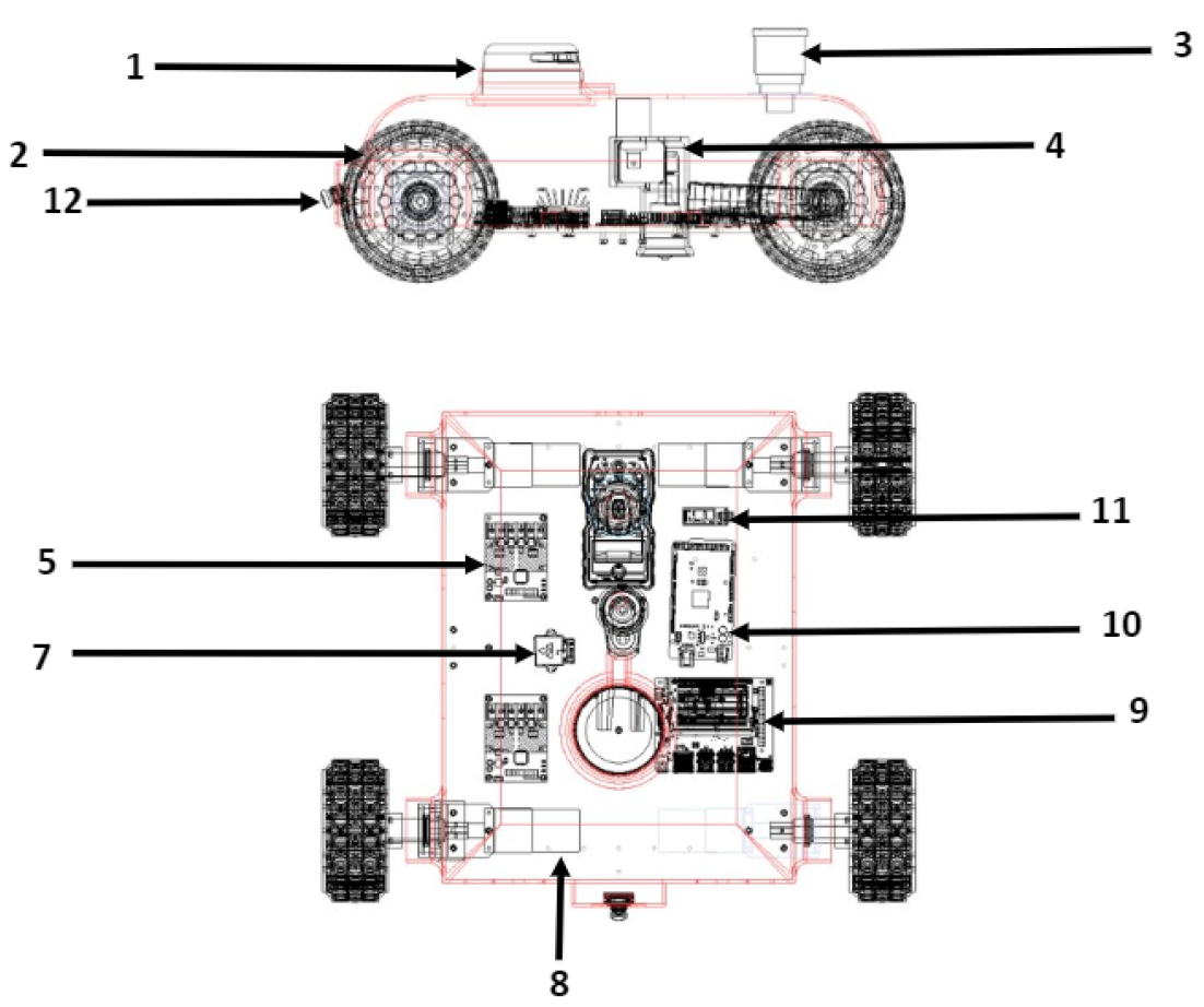
The mechanical structure of the proposed climbing robot is shown in
Figure 1. It has the dimensions of 400 mm × 300 mm × 100 mm with the weight of 14 kg. As the robot is specialized in inspection, it consists of permanent magnetic adhesion mechanism, locomotion mechanism, the frame of the body, and the inspection system that is capable of carrying out metal thickness inspection task. In the adhesion of this kind of applications, even though there are different principles, pneumatic and magnetic are the most suitable ones and magnetic adhesion is more reliable because of no power requirement. Such pneumatic robots can be seen in [
13,
14]. The other adhesion techniques, such as mechanical, electrostatic, and chemical are applied in some robots, like [
15,
16,
17,
18], but not suitable for the application that we are considering. To achieve an efficient climbing robot, it is critical to run the force analysis before we decide the amount of magnets placed on the robot that enables sufficient adhesion, which is discussed in the next session.
Force Analysis
It is of importance that the Sparrow adheres to the ship surface all the way and does not encounter slippage of any form, in order to execute its inspections properly. Thus, all four wheels must be in contact with the target area of the ship hull and possess the required adhesion forces to do so during any operation. The forces must be sufficient to prevent the pivoting of the robot on any particular wheel, which can rotate it away from the wall. Hence, the magnetic adhesion forces exhibited by each wheel has to be increased by tailoring the number of magnetic beads that are placed inside the wheels, if it is required. A force analysis model then becomes necessary to gauge the net adhesion forces of the wheels, which can enable us to deduce whether more magnetic beads are needed per wheel than the current amount placed within.
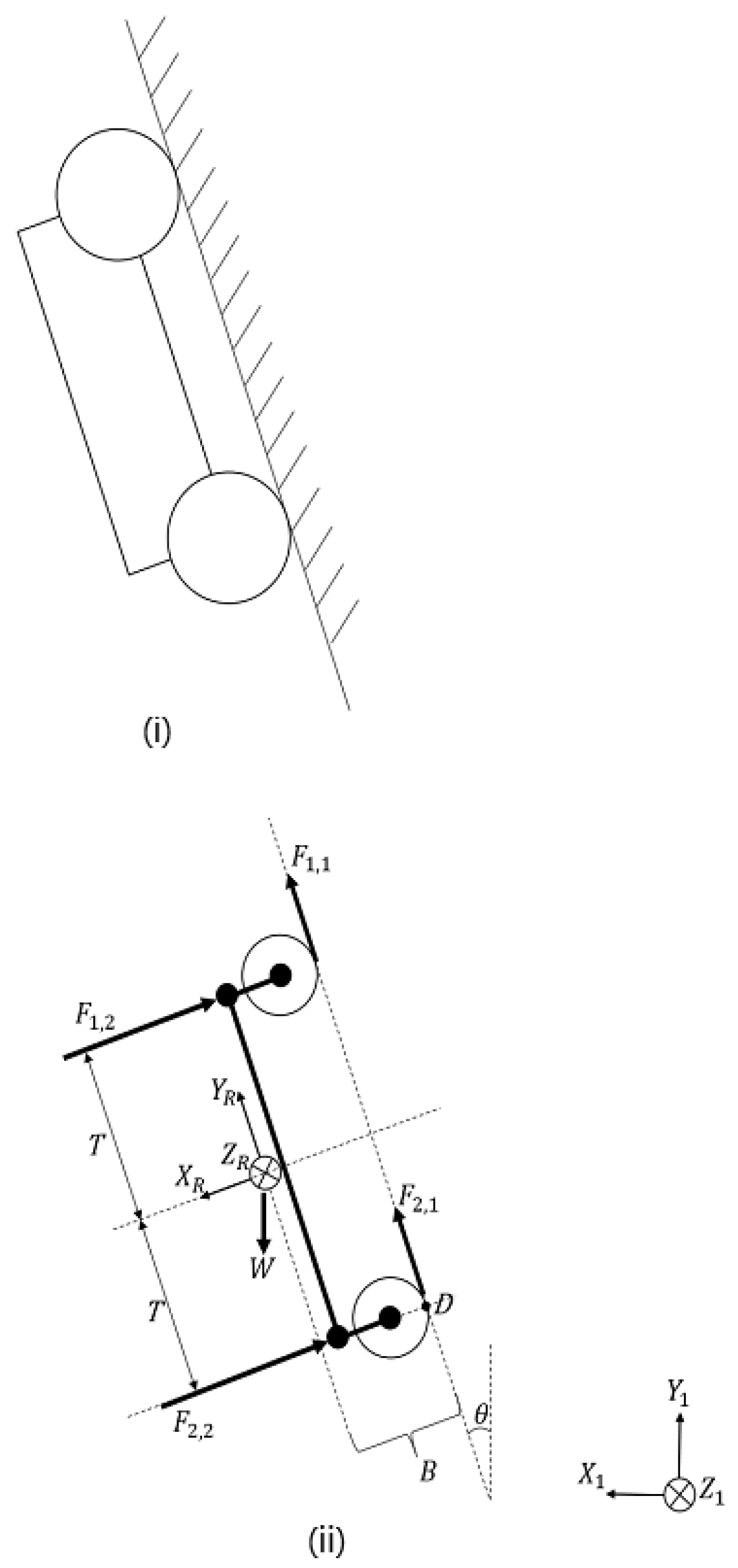
When the robot is at rest on a surface in the vertical position, it experiences gravity, the magnetic adhesion forces from its wheels, the normal contact forces from the surface, and friction that arises in between these, the wheels, and the surface. The force analysis is done on the robot shown to function at an inclined angle facing upwards, which would be a more realistic scenario on a ship hull. The studies conducted to account for various scenarios let to the derivation of a general study technique for the static forces present at equilibrium conditions.
Figure 2 depicts a robot operation model, comprising of a typical setup as well as its representation in a robot coordinate frame.
Our objective is to ensure that the Sparrow is capable of attaching itself to a surface in any arbitrary angle. In
Figure 2,
, and
are the combined, magnetic adhesive forces of the front wheels and back wheels, respectively. Each wheel itself is fitted with a layer of magnetic strips to produce a net adhesion force on each wheel towards the ship surface.
and
are the resulting sliding friction forces while W is gravity coupled together with the mass of the robot. B is the distance between the point of contact of the wheel on the surface, to the Centre of Gravity (CG) of the robot. The distance T represents the length between the respective front/back wheel centres to the CG of the robot.
is the angle of inclination with regard to the slipping surface. Point U is the likely pivot around which the robot is expected to rotate by if the top wheels are designed to exert more adhesive force.
We aim to solve for
and, thus, made the following derivations from the Force Diagram as well as our physical calculations. W = (14 kg)(9.81 m/s
2) = 137.34 N, while 2T = 400 mm and B = 110 mm. The sum of forces in the Y-Reference Frame, encompassing the frictional forces and the relevant force from W, are:
The sum of forces in X-Reference Frame, including the target adhesion forces and the relevant force from W, are:
Taking moments around Point U, we obtain:
Rewriting Equation (
2), we get:
Manipulating Equation (
3), we have:
Substituting Equation (
5) into Equation (
4), we obtain:
The forces of friction are such that
and
, where
is the coefficient of friction between the wheel and ship surface. Thus, Equation (
1) can be rewritten as:
However, Equation (
7) is identical to Equation (
2) and, thus, represents an over-constrained phenomena. Equating both equations together yields:
Taking an arbitrary value of
= 1,
= 45
, which implies that Equation (
2) satisfies all other equations at this angle only. However, our main focus is Equations (5) and (6). Using an angle of 20
in Equations (5) and (6), we derive:
The above values fulfill the following condition needed to prevent the rotation of the robot, which is: .
However, it has to be noted that the overall weight of the robot is at 137.43 N and in order to ensure that the forces from the wheels match up to this weight, more magnetic beads might be required at the front wheels of the robot as well as the back wheels. We designed the magnetic beads according to our analysis in order to maintain the foul free locomotion on the metal surface.
In Sparrow, we used 30 magnets with each magnetic belt to supply the net adhesion force. The wheels have their own motors, hence a total of four motors is used for the four wheels. Each wheel mounted with the motor through a fabricated coupler which provides rigidity for the wheel while locomotion. All other electronic components are fixed on the main chassis of the robot. Each components are mounted with enough gaps to make sure there is no conflict of signal interference that creates sensor error.
3. Robotic Platform Description
The presented inspection robot’s internal components are separated as functional units. Each of the functional units are explained in this section.
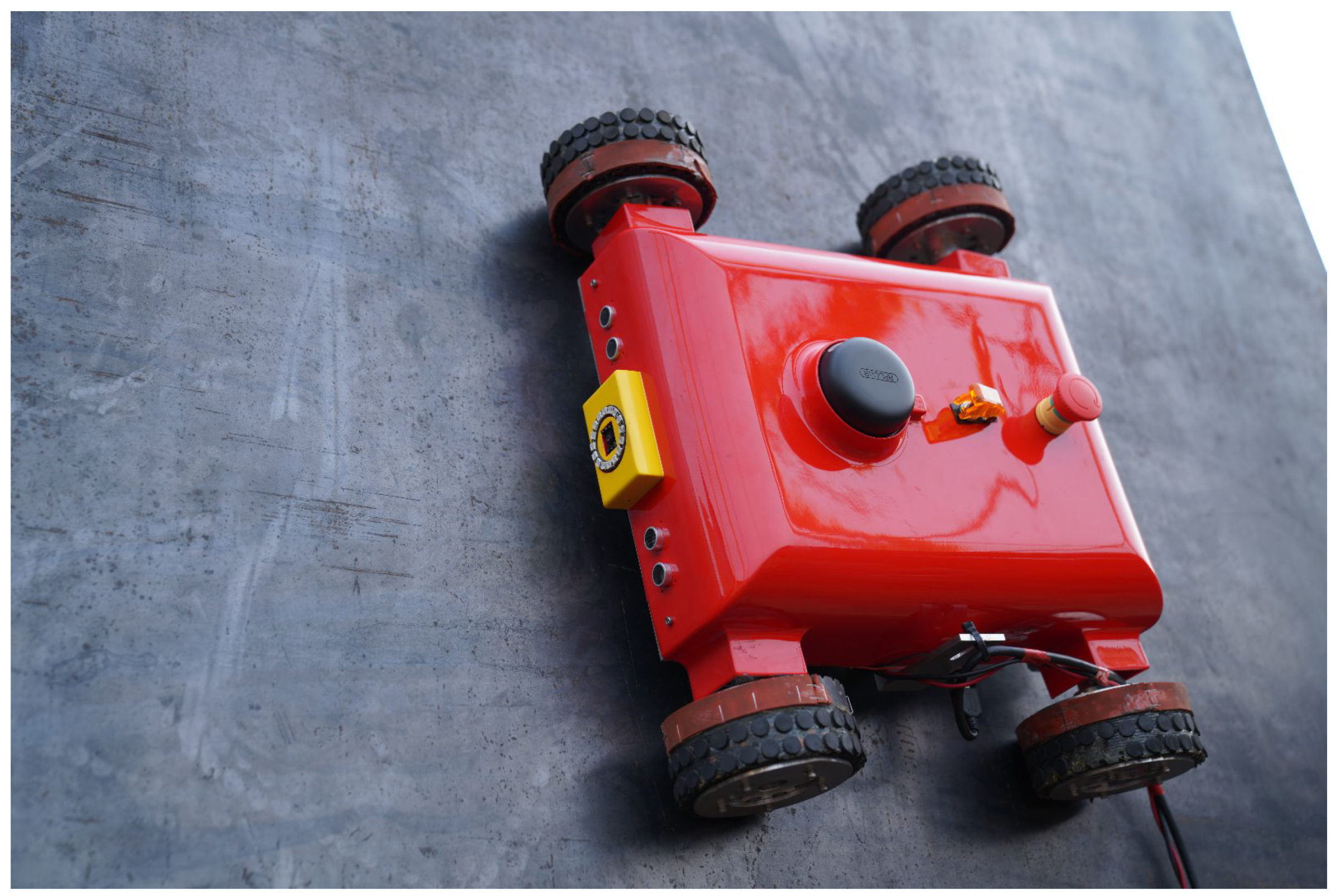
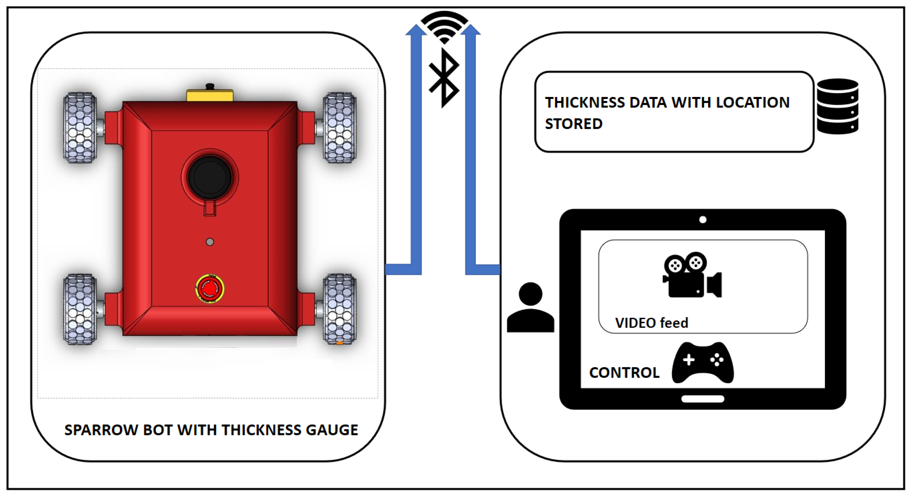
Figure 3 shows the robot on a metal surface at the facility while conducting the experiments. An overview of the proposed architecture is depicted in
Figure 4. It consists of Sparrow bot with thickness gauge, the app with control and video feed, storage for logging the thickness data, and the communication medium. The HMI App screen-layout is split in to two parts, the upper part is for the video feed from the camera, whereas the lower region is for the locomotion control buttons and autonomous button. We used Poly-lactic Acid (PLA) to make the body cover of the robot, 5 mm thick aluminum sheet is used as the base of the robot.
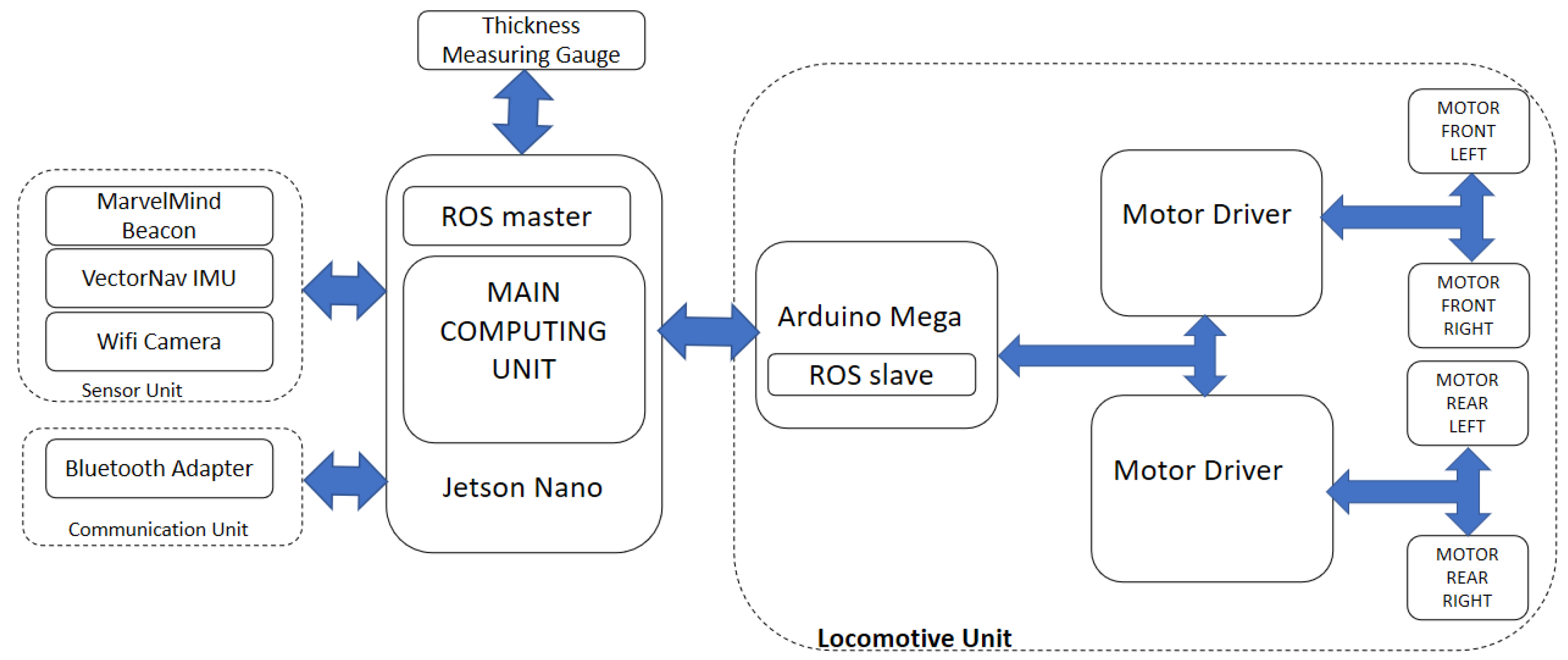
Figure 5 depicts the hardware architecture of the Sparrow robot. It comprises of six functional units, including Jetson Nano as Central Computing Unit, sensor unit comprising of VectorNav IMU, Wireless 1080 p Camera and Marvel mind Beacons, Thickness measuring unit, Locomotive Unit (Arduino Mega 2560 and motors), and communication unit comprising of Bluetooth adapter. Tethered power is opted in the proposed scheme, this makes the operational time of the robot higher. Nevertheless, when using battery, the operational time is very limited and adds weight to the robot.
3.1. Main Computing Unit
The Main Computing Unit comprises of Jetson Nano, a low voltage System on Chip (SoC) single board computer with 4 core ARM A57 CPU and four gigabytes of RAM. Rosserial package is used to interface Locomotive Unit with Main Computing unit. MCU acts as Robot Operating System (ROS) [
19] master and Arduino as a slave to locomote to the goal points.
3.2. Locomotive System
Arduino is used as the Locomotive Control Unit. Roboclaw motor driver 2 × 30A are used to drive the motor. Arduino uses serial communication to communicate with Roboclaw. 18VDC Cytron motor with a high torque of 255 kgcm is used to drive the platform with 94 RPM. The speed and direction for each motor is given from the motor driver. Fundamental movements, like Forward, Reverse, and pivoting, are utilized for locomotion of the robot. Robot’s maximum speed is 0.6 m/s.
3.3. IMU
VectorNav VN-100 is a superior Inertial Measurement Unit that incorporates the most recent MEMS sensor innovation. VN-100 consolidates three-axis accelerometers, three-axis gyros, three-axis magnetometers, along with a 32-bit processor. Yaw angle from the IMU is utilized as the direction of the robot. Serial communication protocol is utilized to obtain the data from IMU.
3.4. Marvel Mind Beacon
Marvel mind Indoor Navigation System with a precision of 2 cm is employed to obtain the location of the robot on the ship hull. Stationary Ultrasonic beacons are interconnected via radio interface to form the reference points, and a mobile beacon is attached to the body of the robot that can be tracked. The real-time location data are taken from the mobile beacon and are given to the ROS master node. Four beacons are set at each corner of the metal plate, can be set at license-free band (433 MHz or 915/868 MHz), size of each beacon is approximately 55 × 55 × 65 mm. Mobile beacons location is calculated by sending ultrasonic signal to the stationary beacons and finding the propagation delay while using trilateration. The map is configured and loaded to the modem. Once the map is loaded, the mobile beacon’s position can be tracked. Marvel-mind provides ROS package for the beacons, with which it is easy to get the data of both stationary and mobile beacon. Calibration is easy with marvel mind beacons, once all of the beacons are switched ON and modem with map is powered. Mobile beacon starts giving the coordinates that are accessed using the ROS package.
3.5. Vision System
The vision framework comprises of a Wi-Fi HD 1080 p camera. Camera placement is done 65 mm above the surface with a tilt of 40 degrees; this is to ensure that the operator is able to see clearly the condition of the hull in-front of the robot shown in
Figure 6. With the real-time feedback from the camera, robot can be controlled precisely. The camera operates at 5 V, with a power rating of three watts. Camera has frame rate of 25 fps at 1080 p, is around 10 g in weight.
3.6. Thickness Measurement Gauge
38DL PLUS Ultrasonic Thickness Gauge from Olympus is used for thickness measurement, range of thickness, which can be measured as 0.08 mm to 635 mm. The gauge is attached to the centre part of the robot using a proper housing, as shown in
Figure 6. This gauge is controlled using a linear solenoid, which, when actuated, makes the gauge to touch the ground and obtain the thickness reading. This solenoid is controlled using a relay and activated using the Arduino micro-controller. The thickness data are logged on with the current position of the robot, i.e., the data from the beacons are taken at the time of logging the thickness measured. In order to protect the probe from damage, the probe is disengaged from the metal surface at the time of pivoting.
5. Experiments and Results
At the time of thickness inspection, the robot might fail to complete the tasks due to position errors and slippages. Such degradation in performance could occur due to the various causes that include speed of the robot’s locomotion or the surface issues or even due to error in operational parameters. A series of exploratory tests were led in the research facility in order to validate and verify the robot parameters. The tests incorporate slippage test and thickness measurement test.
5.1. Slippage Test
Slippage causes error in robot position, which would also lead to an error in thickness measurement. The more the slippage, the more the error. Accordingly, slippage is the primary candidate that needs to be considered in optimising the performance of the robot. For that, the following experiments are done.
Robot is tested on a metal plate having a dimension of 5 m in length and 2 m in height inside the research facility. The metal plate is inclined about 80 to the wall, where the robot is subjected to move in horizontal and vertical path for a fixed time.
Maximum speed of the robot is 0.6 m/s. Four sets of speeds are being used for testing, say 20%, 50%, 80% and 100% (0.18, 0.3, 0.48, and 0.48 m/s).
The slippage for each speed is found out by comparing the wheel encoder values with the data from the beacons in terms of positional coordinates (x, y). Slippage or error is the difference in the distance covered or the path generated from the wheel encoder and the beacons.
Slippage Test Results
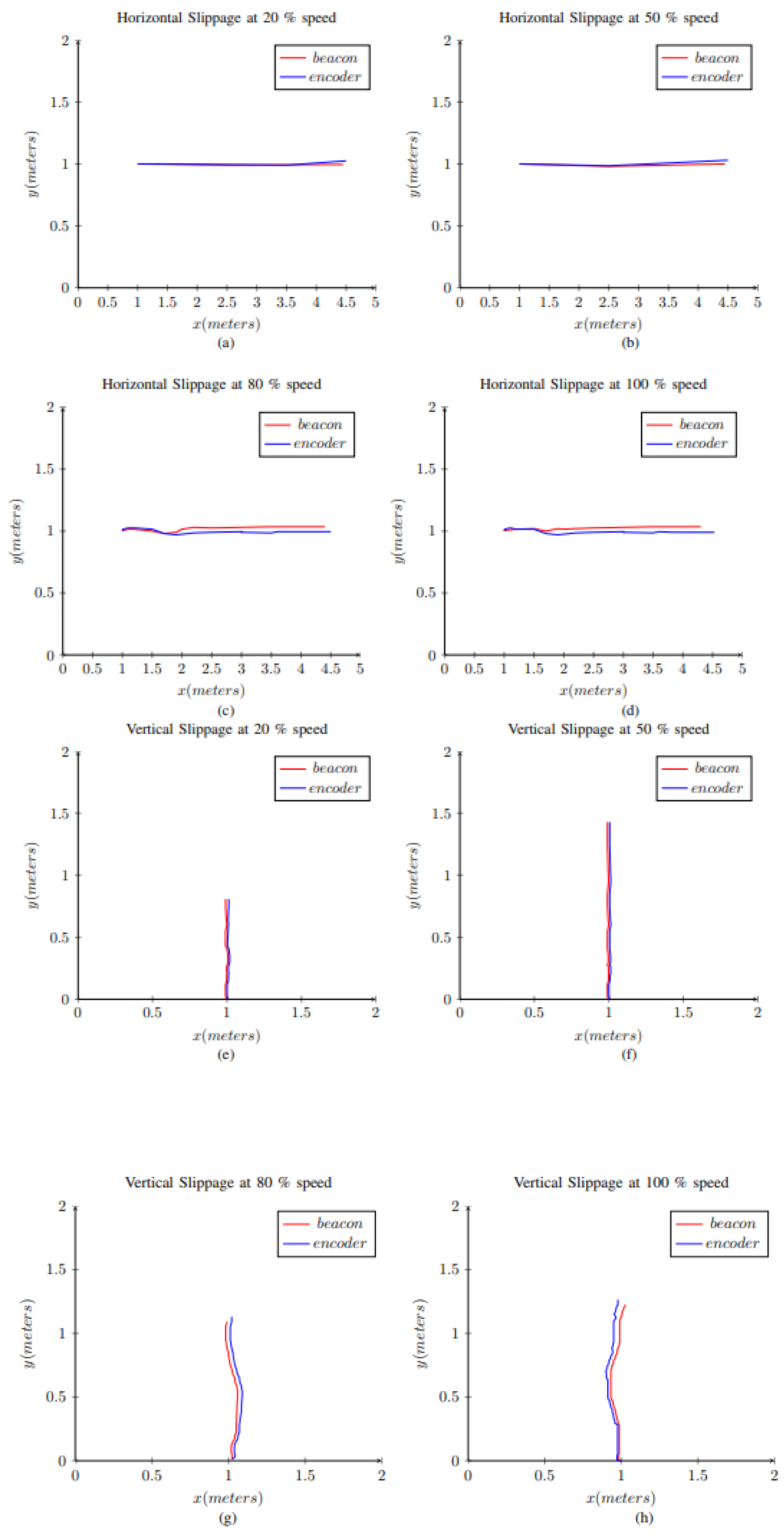
Horizontal slippage and vertical slippage of the robot with different speeds were assessed. For the horizontal slippage test, the robot is set to 20% of its maximum speed and it is placed on the centre of the sheet. Subsequently, the robot is moved forward for 4 m approx and the encoder and beacon readings are taken for the particular time interval. The same steps are repeated for different speeds.
Figure 8a shows the position of the robot on the sheet obtained from encoder and beacon readings. It can be seen that, the plot is a straight line, and there is even no difference between the positional data from the beacons and the encoders.
Figure 8b shows the position of the robot on the sheet obtained from encoder and beacon readings at 50% of the speed. It can be noted that the plotted graph is almost a straight line, and no noticeable difference can be observed from the positional data from encoder and beacon. The horizontal slippage is minimal at 50% speed. In
Figure 8c, the data obtained are plotted when robot is moved at 80% of the speed. It can be observed that the robot is deviating from going in a straight line, and there is a difference in the positional data from encoder and beacon. This confirms that there is considerable slippage when robot is operated at 80% of its speed than the previous case. From
Figure 8d, it can be deduced that the horizontal slippage is maximal when it is operated at 100% speed.
For the vertical slippage test, the robot is set to 20% of its maximum speed and placed on the bottom of the sheet. Subsequently, the robot is moved forward for fixed time, the encoder and beacon readings are observed for the particular time interval.
Figure 8e,f show the robot position when operated at 20% speed and 50% speed. It can be seen that the robot is stable and moves without any noticeable slip. A significant amount of slippage can be observed when the robot is operated at 80% and 100% speeds, as can be observed in
Figure 8g,h.
The test results are shown in
Figure 8 and the average positional error between the encoder and beacon values at different speeds is depicted in
Table 1. This table is deduced by testing the robot on the steel plate at various speeds five consecutive times. From the results, it can be concluded that, with an increase in speed, the slippage increases. However it can also be observed that, at 20% and 50%, the slippage or error is minimal, for best performance, is beneficial to take the highest speed with less error; hence, it is optimal to take 50% as the operating speed. Furthermore, we chose positional coordinates of real-time encoder and beacon values to exhibit the real-time slippage of the robot while moving horizontally and vertically on the plate instead of error between beacon and encoder values. This arrangement is due to, in some cases, the error gap between beacon and wheel encoder being very low to plot. For example, in 20% and 50% speed, the error is very minimal and cannot be visualised on the plot. There is a limitation for doing the experiment inside our facility; longer runs will be performed and analysed in the future work.
5.2. Autonomous Thickness Measurement Test
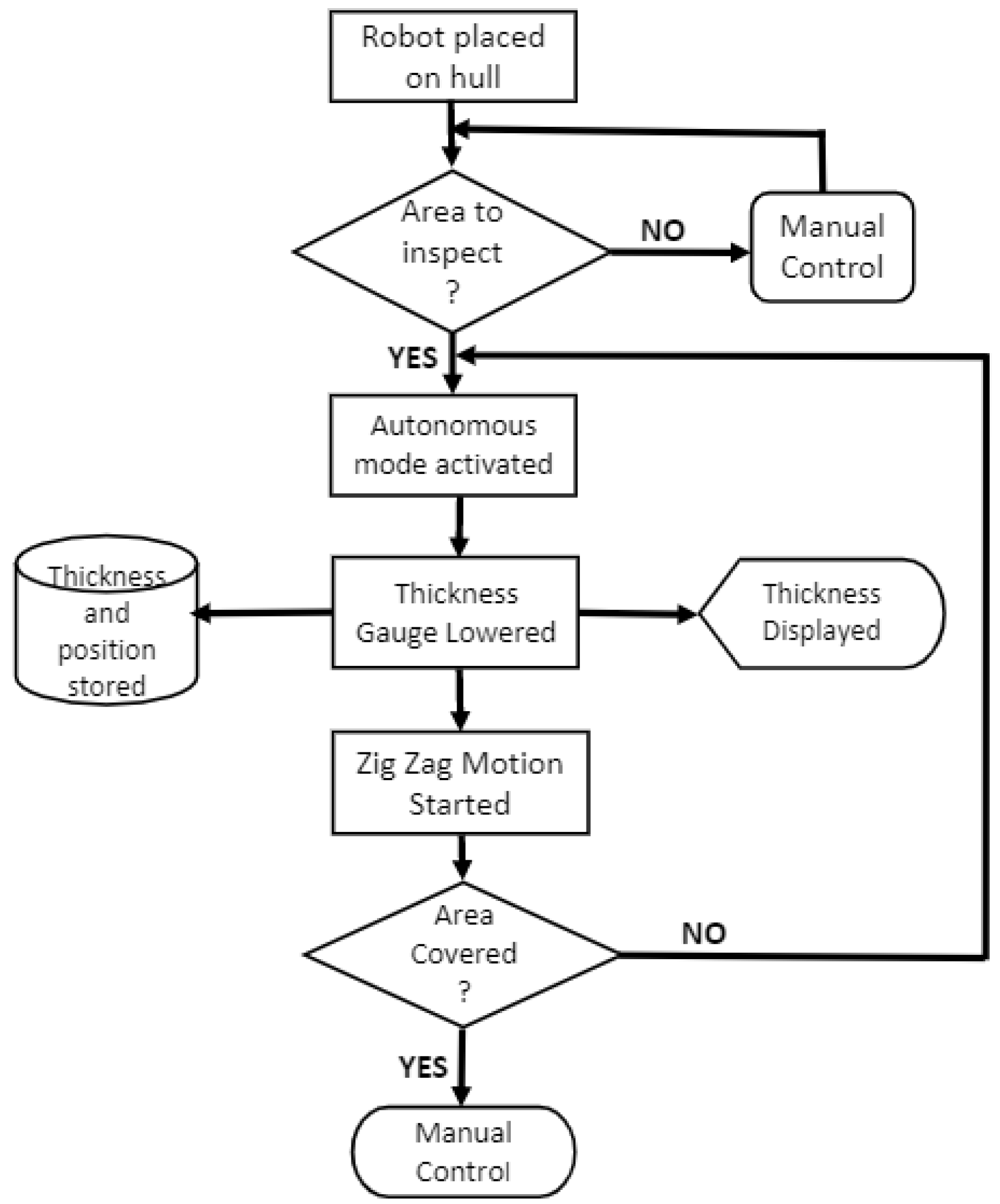
We evaluated the performance of the proposed robot in terms of its thickness measurement ability using two sets of experiments in three different scenarios. The experimental scenarios were varied by changing the thickness of the plate. In our experiments, we used metal plate with thickness of 5 mm, 8 mm, and 10 mm. The considered metal plates have a dimension of 2 m in length and 1.5 m in height. In the first set of experiments for all considered metal plates, the robot is allowed to perform the thickness measurement task at the centre of the plate for an area of 0.7 m × 0.7 m. In the second set of experiments, we modified the plates by welding a 5 mm thick metal piece at the back of the test bed with 200 mm in length and 20 mm in width. In both experiments, the robot is operated in the following sequence
manually controlling the robot to move to the starting point;
autonomously covering the 0.7 m × 0.7 m area in zigzag path with enabled thickness measurement data logging; and,
returning back to the manual mode after completing the coverage.
During the autonomous operation, the robot moves in a horizontal direction for 0.7 m by continuously measuring the thickness values. Similarly, the robot performs continuous thickness measurement during the vertical climbing. The robot climbs in the vertical direction for 0.1 m. While performing, the pivot turns, the robot disengages the measuring system and breaks the probe contact with the surface in order to protect the probe. In both vertical and horizontal motion, the measured values are stored on the data logger continuously along with the robot’s pose. The logged values are post processed in order to visualise the thickness evenness on the considered plates.
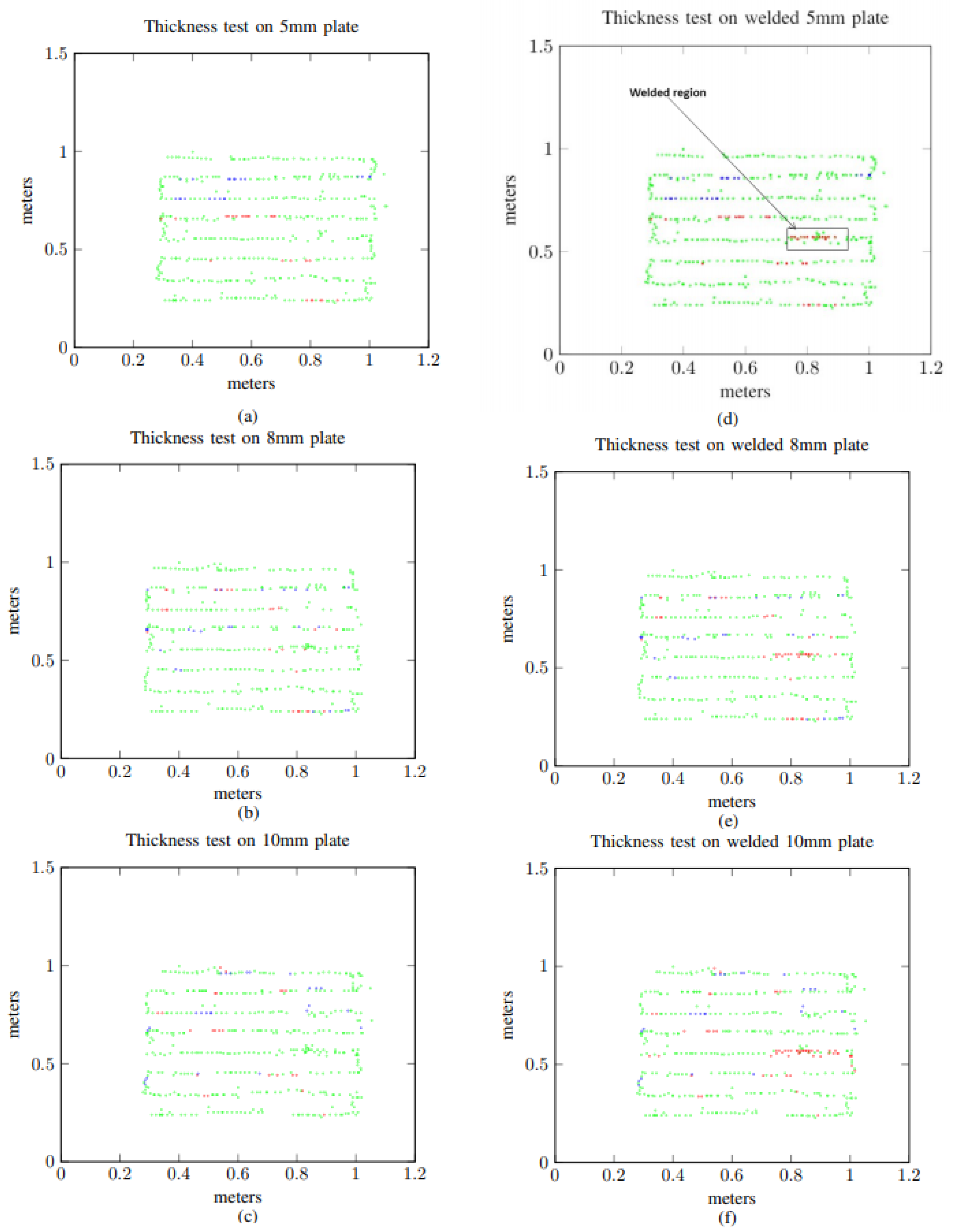
Simple MATLAB program is created to visualise the logged thickness value. The algorithm would plot the logged information on a two-dimensional (2D) graph. Each thickness value is plotted as a colored circle with respect to the position of the robot. Three colours red, green, and blue are used to represent the measured thickness values. The algorithm chooses the appropriate colour for the circle to plot the particular thickness value. For instance, if the single measured value is lower than the actual thickness of the plate, then the algorithm would choose blue, for a higher value it chooses red, and green for actual. After the plot is generated, the analysis will be done for further steps in the inspection. The algorithm will compute the percentage of green points at the end of each trial from the number of green points logged from the total recorded points.
Thickness Measurement Results
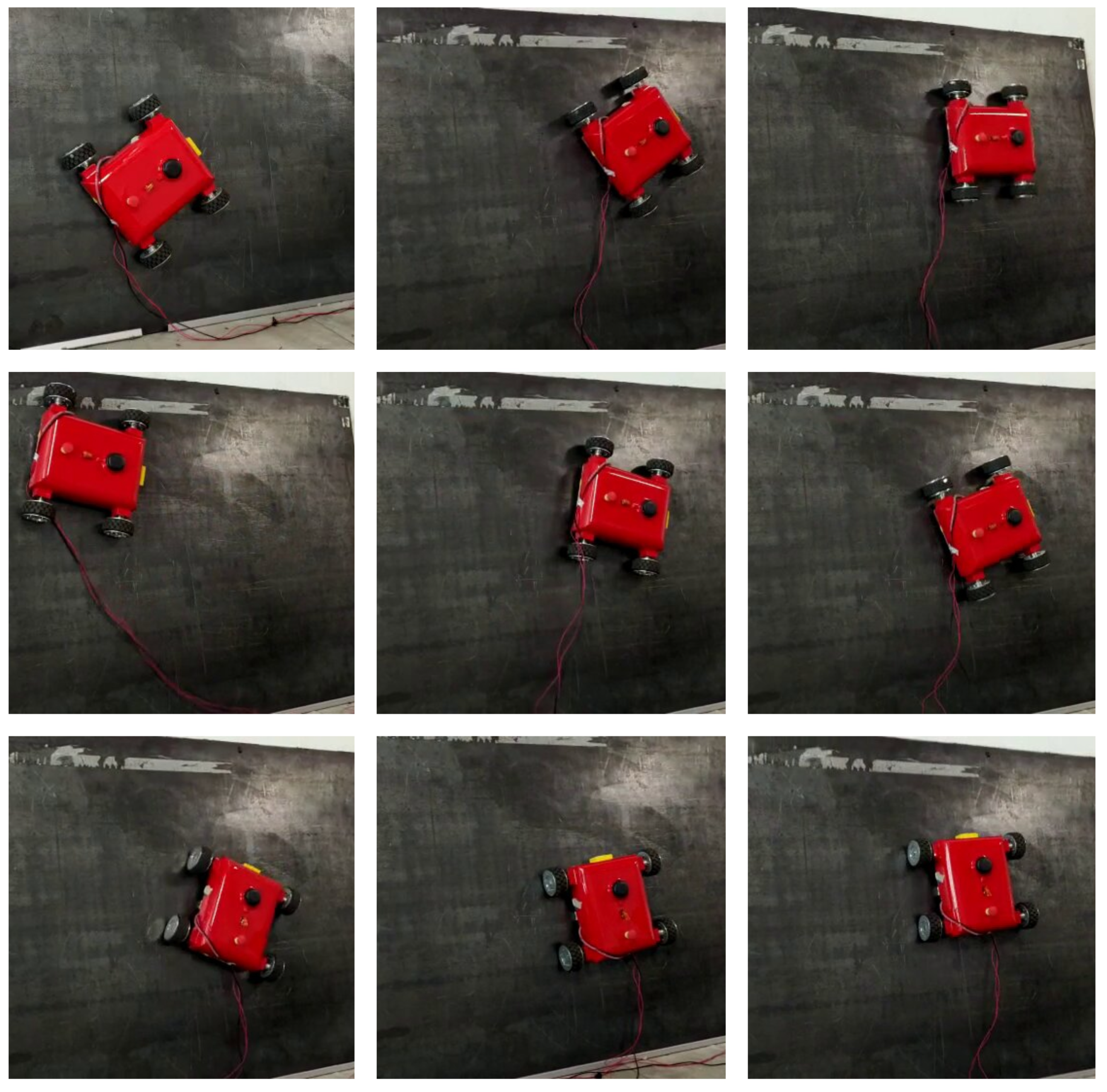
The thickness measurement trials were started by placing the metal plate vertically and attaching the robot on the same. Initially, the robot was manually controlled to move the robot to the centre and the autonomous mode was selected. The robot continued the zigzag motion by measuring the thickness of the plate.
Figure 9 shows some robot screen shots while performing the thickness trials. Once the coverage is completed the robot is retrieved to visualise the logged data by post processing it.
Figure 10a–c show the plots generated form the visualisation program for the experiments conducted on the 5 mm, 8 mm and 10 mm plates. All generated plots have more than 96% green circles that show the proposed robot could successfully measure the thickness value with considered scenarios. There are some places we can witness the red circle and blue circles in the results generated from all the experiment conducted. This is due to the less thickness, there are few slippages that trigger the robot to align its orientation and path which affect the probes contact on the plate leads to error reading. Also the error of localisation is causing the points to deviate and scatter. In some places we noticed that the false reading happened because of plate surface unevenness.
In the second set of experiments, the metal piece was welded at the backside of the test bed. Afterwards, similar procedures were run to conduct the experiments and generated the plot by retrieving the robot at the end of each trial. Here, the percentage of green circles generated is reduced to 93% because of the welded metal piece. The provoked plot for the conducted experiments is shown in
Figure 10d–f with sub-figures illustrating the results from 5 mm, 8 mm, and 10 mm. Because a small metal piece was welded in every test bed, all of the results provide more red circles that depict the welted piece that is shown in
Figure 10d. Additionally, in this second set of experiments, there had been some slippages during the trials on the metal plates, and had errors in localisation that lead to generating more red and blue circles. However, from the results with all test bed, the welded area can still be identified. Through this study, autonomous metal thickness robot has been demonstrated for the first time that inaugurates a significant untapped research and development opportunity related to ship hull inspection applications.

 ,
, 

