Article

Numerical Prediction of Welding Distortion Considering Gravity Force on General Ship Grillage Structure by Elastic Finite Element Method Using Inherent Strain

Department of Transportation and Environmental Systems, Hiroshima University, Higashi-Hiroshima 739-8527, Japan
*
Author to whom correspondence should be addressed.
J. Mar. Sci. Eng. 2020, 8(6), 454; https://doi.org/10.3390/jmse8060454
Submission received: 11 May 2020 / Revised: 15 June 2020 / Accepted: 17 June 2020 / Published: 20 June 2020

Abstract

:
The accurate numerical prediction of welding deformation is important to improve the structural safety of ships and offshore structures in heavy industries. The precise reflection of the real working condition in the numerical prediction is an essential factor to improve its result. In the present study, the effect of the gravity force on numerical prediction of the optimal welding sequence of a general ship grillage structure was validated with the introduction of a new boundary condition in which the structure is placed over rails. Additionally, the direction of the gravity force of welded structures could be changed at the final assembly process according to the production plan. The effect of the gravitational orientation on the final welding displacements was also investigated herein. The elastic finite element method using the inherent strain, interface element, and multipoint constraint function was introduced to analyze the welding deformation. This study validated the influence of the gravity force on the numerical prediction of welding displacements in a general ship grillage structure.

1. Introduction

Welding is the most convenient method to build various steel structures such as ships and offshore structures. However, welding deformation is inevitable due to its extremely high heat operation. The rapid change in temperature from heating to cooling along a welding line causes local shrinkages. Thus, improvement in the accuracy of welding distortion prediction is one of the most essential factors to design a welding process efficiently. In recent decades, many studies have been conducted to improve the numerical method for accurately predicting welding distortion. However, previous studies have not considered the effect of the gravity force on the process of welding in the numerical simulation. In a structural analysis by the finite element method (FEM), the effect of the gravity force is not a negligible factor. In particular, the gravity force of a large structure is massive. Thus, the reflection of the gravity force in the numerical prediction of welding distortion is essential.
In heavy industries, each compartment of a structure is separately welded prior to the final assembly process. During the final assembly process, the direction of the gravity force could be changed according to the designed position of the separately welded compartment of a structure as showing in Figure 1. Even if the welded compartments are corrected and straightened to eliminate deformations at the first step, due to the change in the direction of the gravity force, misalignment, and displacement can be reproduced at the final assembly process. Therefore, a numerical simulation considering the change in direction of the gravity force is essential for efficiently designing the welding process.
To overcome the limitations of welding experiments, the computational approach based on FEM has been widely employed. Generally, the welding mechanism of residual stress and deformation has nonlinear characteristics. The thermal elastic plastic (TEP) method has been widely used to estimate the result of welding operations on a structure accurately. However, this method requires a considerable amount of time to calculate even a simple welding problem.
Thus, most of the recent studies have applied the inherent strain theory using the elastic FEM to predict the amount of welding displacement in a large and complex structure without involving excessive hours of calculations. Ueda [1] experimentally verified a numerical approach applying the inherent strain for calculating the welding residual stress. The effectiveness of the elastic FEM based on inherent strain to predict the welding deformation and residual stress in multi-pass narrow gap welding was validated [2]. To account for both the welding’s local shrinkages and misalignment in the weld joint, the interface element method was introduced to the elastic FEM using inherent strain [3]. The numerical method using the elastic FEM with inherent strain for predicting the welding deformation of a large structure was investigated by comparing computational and experimental databases [4]. Deng [5] carried out experiments to validate the elastic FEM based on the application of inherent strain for precisely predicting the welding distortion of a low carbon steel butt-welded joint with 1 mm in thickness. Ueda [6] investigated the characteristics of the inherent strain distribution in a butt weld and found that the patterns vary little with changes in the welding condition. Shadkam [7] validated the effect of sequence and shape of stiffeners on the reduction of stiffened panel’s welding distortion by the elastic FEM using the inherent strain theory. Liang [8] studied the influences of heat input, welding sequence and external restraint on the twisting distortion of a curved stiffened panel by mean of the computational approach based on the inherent strain theory and interface element method. Woo [9] validated the systemic method to recommend the optimal welding sequence for the mitigation of welding displacements by the elastic FEM using inherent strain theory. Woo [10] proposed an applicable systemic method for efficiently positioning clamps and strongbacks for minimizing welding deformation with introducing optimal welding sequence.
Based on the above discussed studies, the prediction of welding distortion of a large and complex structure by the elastic FEM with inherent strain has been clearly verified by the comparison of experimental results. Moreover, the effect of the optimal welding sequence on the mitigation of welding displacements of welded structures was validated by the database of the numerical predictions using the inherent strain theory and experiments. In the present study, to improve the numerical prediction of welding displacement in ships and offshore structures considering real work environments in heavy industries, the effect of the gravity force under real production conditions is numerically validated.

2. Elastic FEM Using Inherent Strain

2.1. Basic Concept of Inherent Strain and Inherent Displacment

While processing the cycle of heating and cooling along welding lines, the component of total strain ε t o t a l along welding lines is given as Equation (1). After the welding heat finally disappears, the total strain ε t o t a l is changed to the inelastic strain and it is known as the inherent strain ε i n h e r e n t as expressed in Equation (2). The plastic strain ε p l a s t i c is representative of the inherent strain ε i n h e r e n t because the creep strain ε c r e e p and the phase transformation ε p h a s e are negligibly small [11]. The inherent strain ε i n h e r e n t causes three different inherent displacements along welding lines, i.e., transverse shrinkage S , longitudinal contraction force F t , and angular deformation θ , as shown in Figure 2 [9]. In welding, the source of welding residual stress (inherent strain) is considered to be produced only in a limited portion near the welding line [11]. Hence, in the application of the inherent strain method to the FEM, the inherent strain is assumed as constantly existing in limited elements that are near the welding lines, as depicted in Figure 2.
ε t o t a l = ε e l a s t i c + ε t h e r m a l + ε p l a s t i c + ε c r e e p + ε p h a s e
ε i n h e r e n t = ε t o t a l ε e l a s t i c = ε t h e r m a l + ε p l a s t i c + ε c r e e p + ε p h a s e

2.2. Caculation of Inherent Deforatmion and Inherent Strain

Based on the experiment data of CO2 arc butt-welding of a plain plate (200 mm × 200 mm × 10 mm) using high-strength steel (HT50), Equations (3)–(9) were derived [12] to calculate the inherent displacement. In these equations, the amount of inherent deformation is determined by the amount of heat input Q * of CO2 arc butt-welding. In [13], it was validated that the relationship between heat input Q * and net heat input Q n e t in the welding process is decided by the thickness h of the welded steel plate, and it can be expressed as Q * = Q n e t / h 2 . In [14], it was concluded that the longitudinal shrinkage is generally evaluated by the contraction force F T , and; the relationship between the contraction force F T   and the net heat input Q n e t is derived as Equation (9). Table 1 and Table 2 present, respectively, the conditions of welding and the mechanical properties of HT50 steel.
  • Transverse Shrinkage
    S = C t ( L ) S 0
    S 0 = { 1.16 × 10 3 Q n e t / h     ( Q * 6.27 ) h { 1.44 × 10 4 [ ( Q * ) 2 Q * ] + 2.5 × 10 3 }     ( 6.27 < Q * 20 ) 2.85 × 10 3 Q n e t / h     ( 20 < Q * )
    C t ( L ) = [ 4 t a n 1 ( L / 200 ) + ( L / 100 ) × log ( 1 + 40000 / L 2 ) ] / 3.74
  • Angular Deformation
    θ = C a ( L ) θ 0    
    θ 0 = { 1.44 × 10 3 Q *       ( Q * 6.27 ) 1.06 × 10 1 Q * / { ( Q * 6.16 ) 2 + 73.6 }     ( 6.27 < Q * )
    C a ( L ) = [ 8 t a n 1 ( L / 120 ) + ( 1 + v ) ( L / 60 ) × log ( 1 + 14400 / L 2 ) ] / 8.84
  • Longitudinal Shrinkage (Contraction Force)
    F T = 0.2 Q n e t    
    where
    • θ 0 is the angular deformation at a welding length of 200 mm;
    • C t ( L ) is the welding length compensation coefficient for lateral shrinkage;
    • C a ( L ) is the welding length compensation coefficient for angular deformation;
    • F t is the vertical contraction force;
    • L is the welding length [mm];
    • v is Poisson’s ratio;
    • Q n e t is the net heat input [J/mm];
    • h is the plate thickness [mm];
    • Q * is Q n e t / h 2 [J/mm3];
To derive equations for the definition of the correlation between inherent deformation and strain, the width of the element that is applied by the value of inherent strain is necessary. If the maximum temperature is T = σ Y / E α   (α: linear expansion coefficient) and the heat source is approximated to the instantaneous line heat source, the width b is defined as Equation (10), [14].
b = 0.117 ( α / c ρ ) ( E / σ Y ) Q n e t
where
α is the linear expansion coefficient [1/k];
c is the specific heat [J/kg/k];
ρ is the density [kg/mm3];
σ Y is the yield stress [MPa];
When the element width is b, the inherent strain of longitudinal shrinkage, transverse shrinkage and angular distortion can be defined as Equations (11)–(13), [12]. Angular deformation is defined as the bending stress in elements where the inherent strain is applied. The progress of the angular deformation changes the inherent strain. k = θ / b is the curvature of the deformation.
ε l * = 0.5 ( F T / ( E h b ) )
ε t * = 0.5 ( S / b )
ε a * = h k  
where
ε l * is the inherent strain of longitudinal shrinkage;
ε t * is the inherent strain of transverse shrinkage;
ε a * is the Inherent strain of angular distortion;

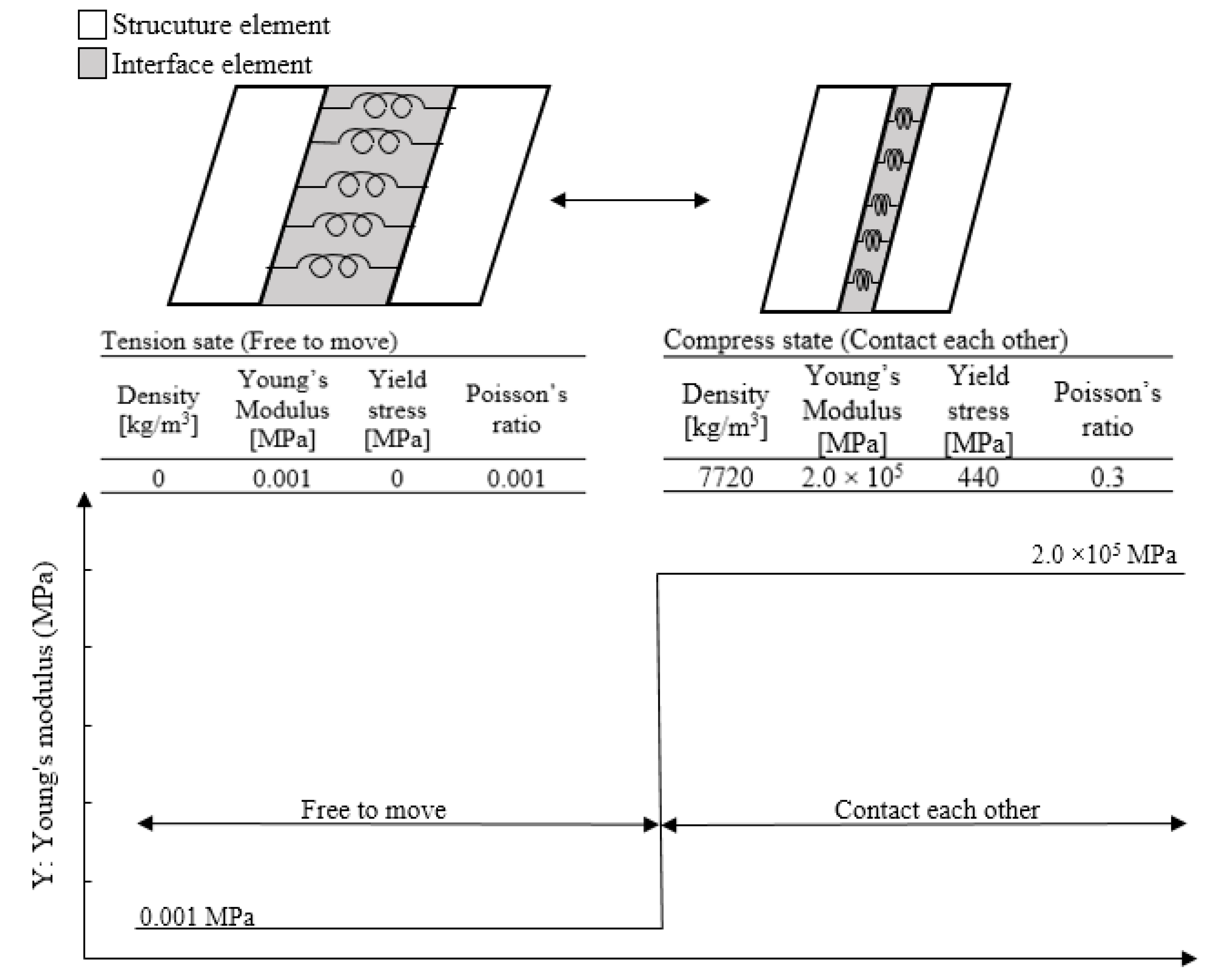
2.3. Interface Element Method

During processing of the iteration logic in the elastic FEM to simulate the sequential welding, the definition of the gap between not welded parts is essential. To reflect this relationship in the elastic FEM, the interface element method is introduced herein. While processing the numerical simulation for the welding sequence, each step involved verification of the state of stress in all the assigned interface elements, to distinguish whether it was a tension or compression case. In the state of tension case, the material property of the interface element changed as air, with the different parts moving freely, without mechanically impacting each other. This indicates the gap between two parts. In the state of compress case, the material property of interface element changed as mild steel to allow the different parts to push each other. This iteration could be considered to be the nonlinear simulation. Thus, the interface element is defined as a nonlinear spring, as represented in Figure 3 [10].

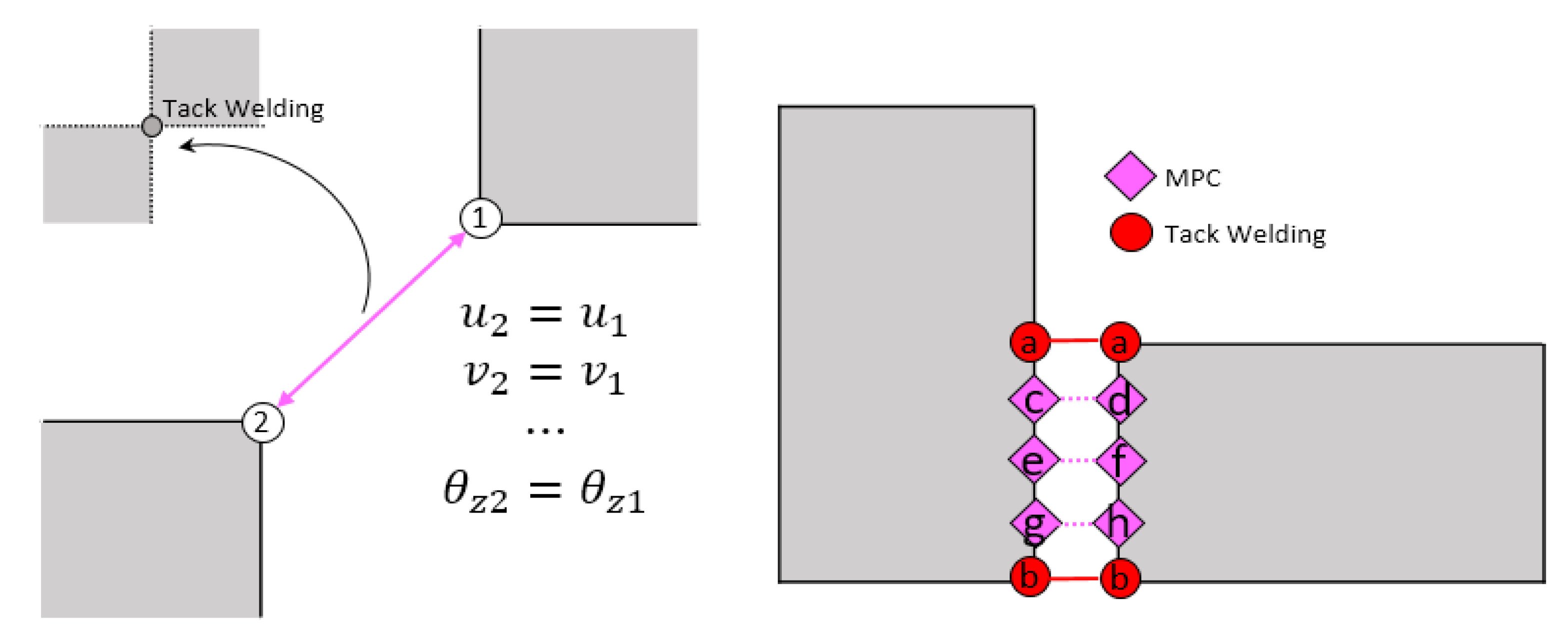
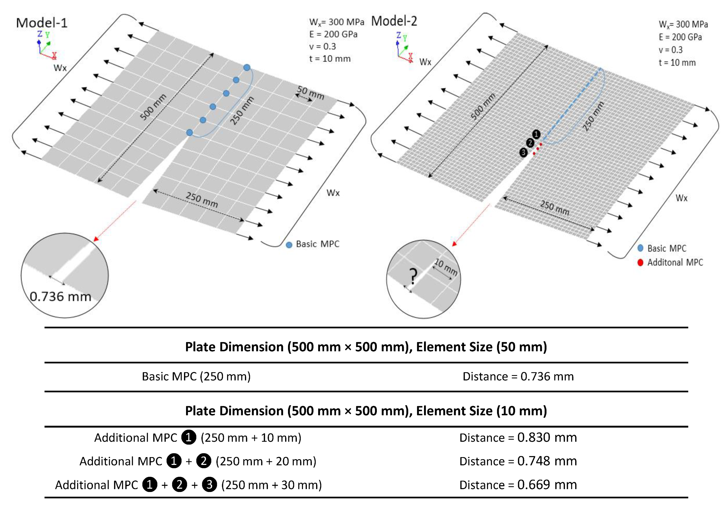
2.4. Multipoint Constraint Function
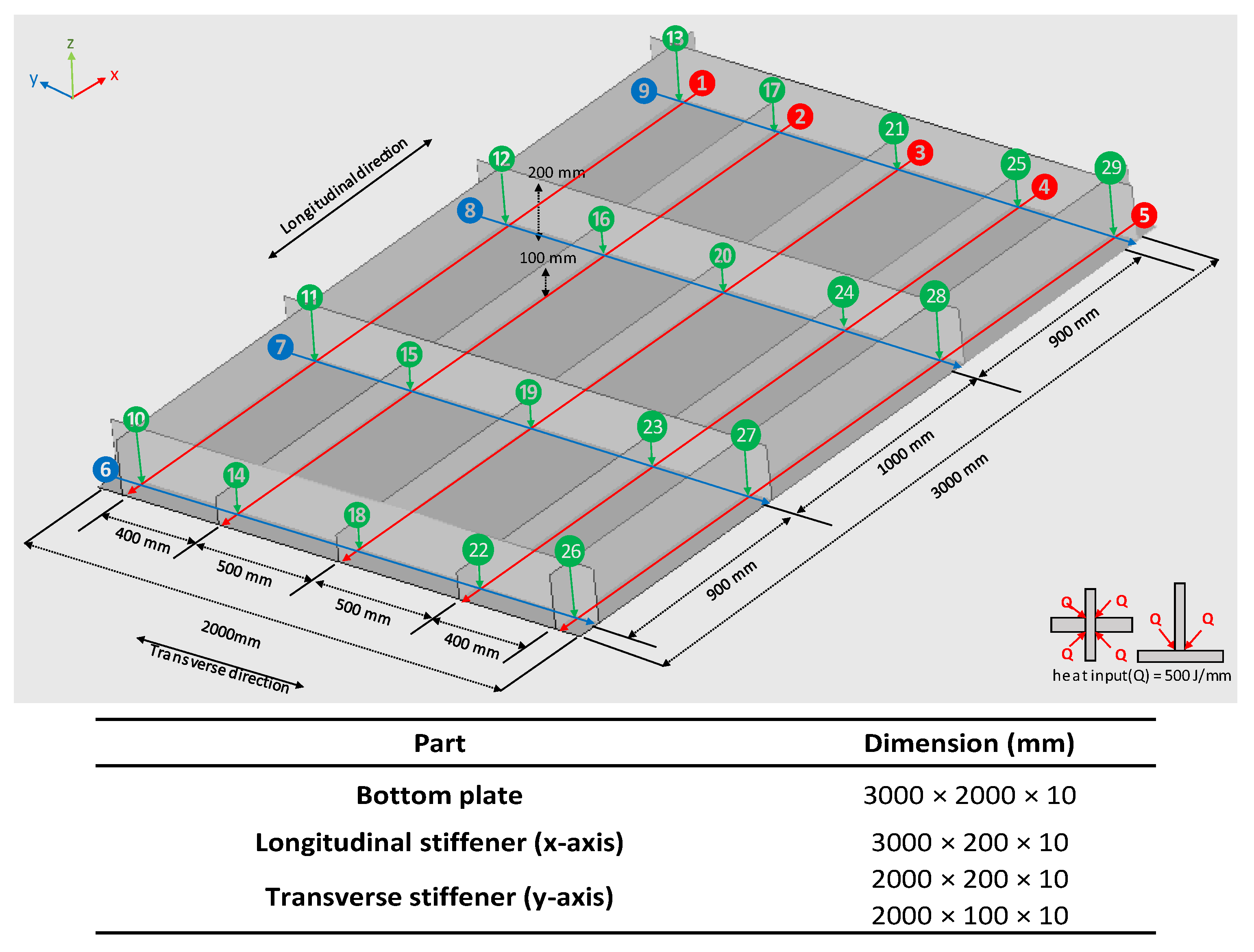
The multipoint constraint function (MPC) is an advanced method for the combined FEM analysis to connect different nodes and degrees of freedom. In Figure 4, Nodes 1 and 2 are originally positioned at two different elements. By using the MPC, these two nodes are connected to each other, and can be defined as attached elements. The MPC can change the state of one node to work as a master or slave. In this study, tack welding (to temporarily attach plates) is employed in the initial analysis model. As shown in Figure 4, Nodes a and b are initially connected using the MPC as tack welding. In addition, Nodes (c, d), (e, f), and (g, h) install the MPC to be activated at the assigned welding order [10].
In the present study, a tack welding is just expressed by connecting two nodes using MPC. To validate the physical effect of the tack welding presented by MPC on the constraint of the displacements in the numerical simulation, simple cases are simulated as Figure 5. In Model-1 (Left in Figure 1), two plane plates (500 mm × 250 mm) are partly attached with basic MPC and pulled each other sides by the uniformly distributed load in x direction. In this condition, the distance of the two points of the not attached edge is measured. In the case of element size of 50 mm, the distance is 0.0736 mm. To validate the specific range of the effect of MPC on the displacement, with changing the size of the element to 10 mm and adding additional MPC in Model-2 (Right in Figure 5), the distance of the two points is measured. The additional two MPC (❶ + ❷) in Model-2 produces the similar distance to Model-1. Hence, in the numerical simulation with the model basically using element size of 50mm, an MPC is assumed to be the tack welding of 20 mm under the assumption that a tack welding joins members with the same rigidity as the base metal. Thus, introducing MPC to express a tack welding is reasonable in this study.

3. Analysis Model

To compare the effect of the gravity force on the numerical prediction of the optimal welding sequence of a welded structure, the general ship grillage structure, which was used in the previous study [9] is introduced in the present study. Figure 6 illustrates the dimension of the analysis model.
HT50 steel is used in the structure, as presented Table 2. CO2 arc butt-welding is used herein as Table 1. All the cross-section upper and bottom points were originally installed MPC to assume tack welding and outline the complete structure before being in a full welding operation. A total of 29 welding lines are used, categorized in three groups, as follows: longitudinal (1–5), transverse (6–9), and vertical (10–29). The 29 welding lines with their numbers are schematically drawn in Figure 6.

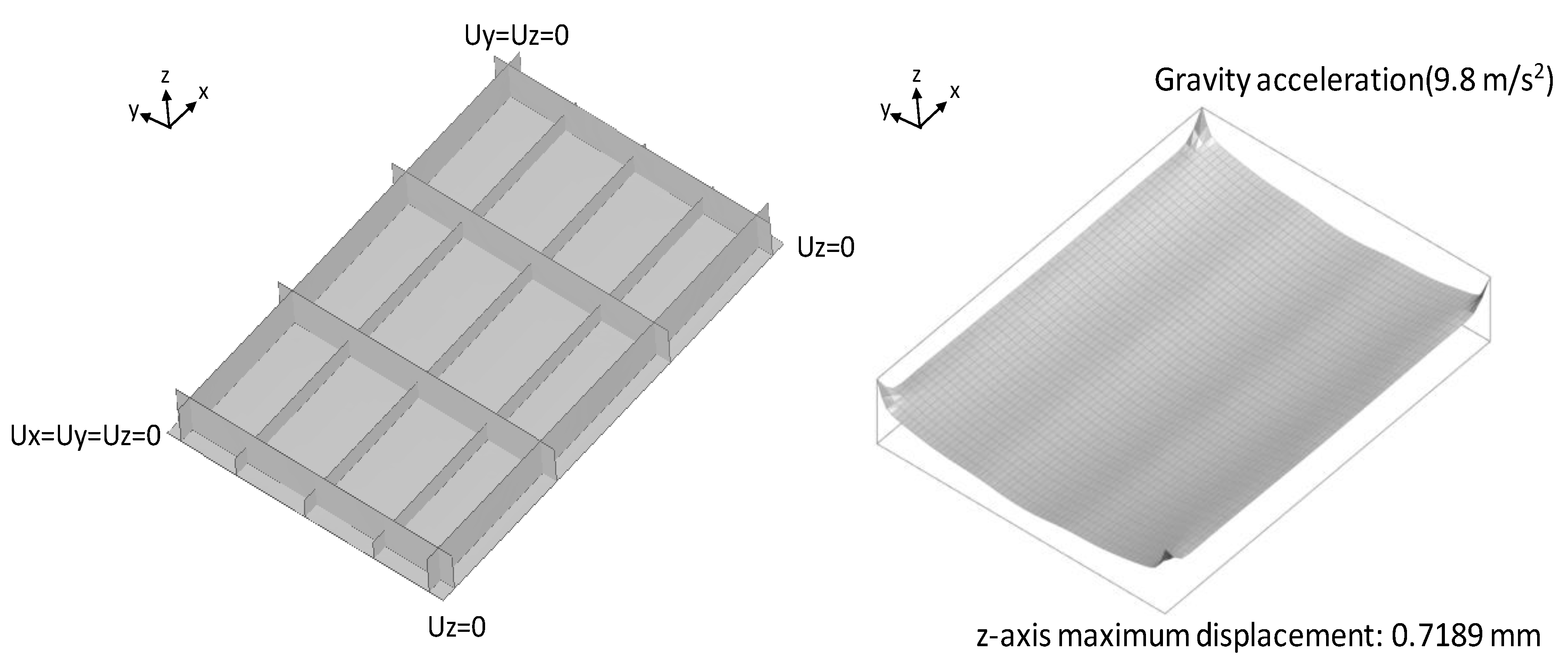
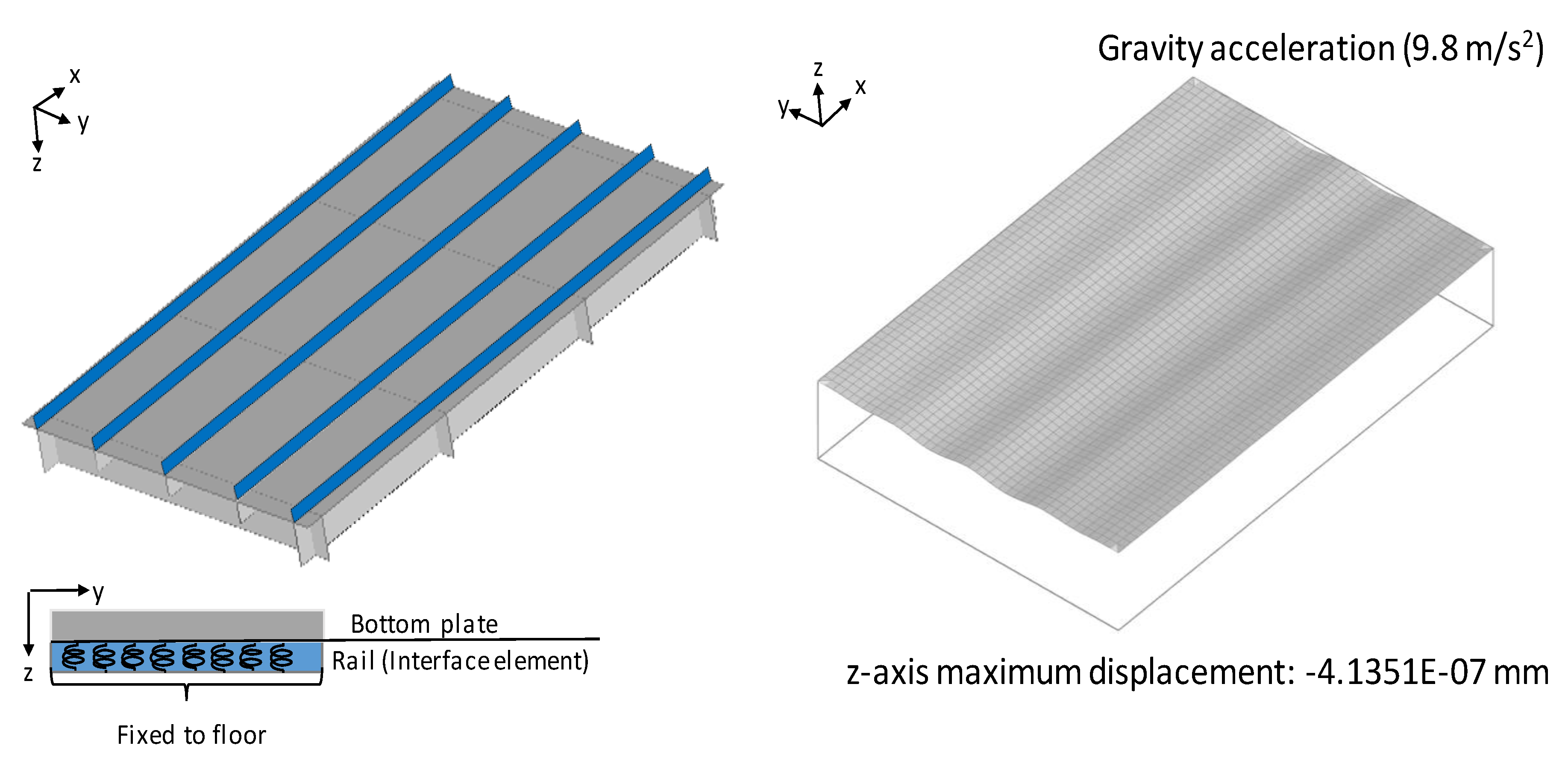
4. Boundary Condition of the Rails Considering the Gravity Force

Previous studies on the prediction of welding distortion using a numerical simulation did not consider the effect of the gravity force in the welding process. The magnitude of the gravity force and its influence on the structure depend on the dimension of the structure and the background condition of the welding work. Thus, the introduction of a boundary condition reflecting the real working condition is important to improve the numerical simulation analyzing the welding distortion. Previous studies generally introduced a simple boundary condition to control only the rigid body motion of the structures employed in the numerical simulations. Representatively, Figure 7 shows the simple boundary condition to constrain the motion of a general ship grillage structure. Based on the boundary condition, the gravity is applied to the structure prior to the beginning of the welding process. In Figure 7, the bottom plate of the general ship grillage structure is obviously deformed in the gravity direction, except at the position of the four corners, where fixed boundary conditions are given. The z-axis maximum displacement of the bottom plate is approximately 0.72 mm. In terms of the hazardous initial deflection in heavy industries, the shape of the deformation caused by the gravity and the magnitude of the z-axis maximum displacement are not negligible and are ideal for the considering real working environment.
A bottom plate is positioned on the floor or rails when stiffeners are welded to the bottom plate, as shown in Figure 8 [15]. In particular, with the recent introduction of the automated robot welding method, rails are widely used to support a bottom plate for improving the productivity of the work process in heavy industries. In the present study, to reflect the real working condition when the bottom plate is positioned on rails, the rails are positioned behind the longitudinal stiffeners of the general ship grillage structure, as depicted in Figure 9. The interface element is introduced to define the mechanical relationship between the bottom plate and rails, which are considered to be touching each other when processing the numerical simulation for the welding sequence. The interface element works as the boundary condition so that all the nodes of the bottom plate along the rails can move in any direction without restriction, except for the -z direction. In Figure 9, based on the newly introduced boundary condition, the z-axis maximum displacement of the bottom plate owing to the effect of gravity is approximately 4.13E-7 mm. It is a negligibly small size compared to the previous z-axis maximum displacement (0.72 mm) and could be considered to be the ideal condition prior to beginning the welding process.

5. Effect of the Gravity Force under the Rail Boundary Condition on Welding Sequence

Woo [9] proposed a method to systemically order the welding sequence for a general ship grillage structure under the basic boundary condition as shown in Figure 8. In the present study, the proposed method to order the welding sequence systemically was carried out under the rail boundary condition considering the gravity force.

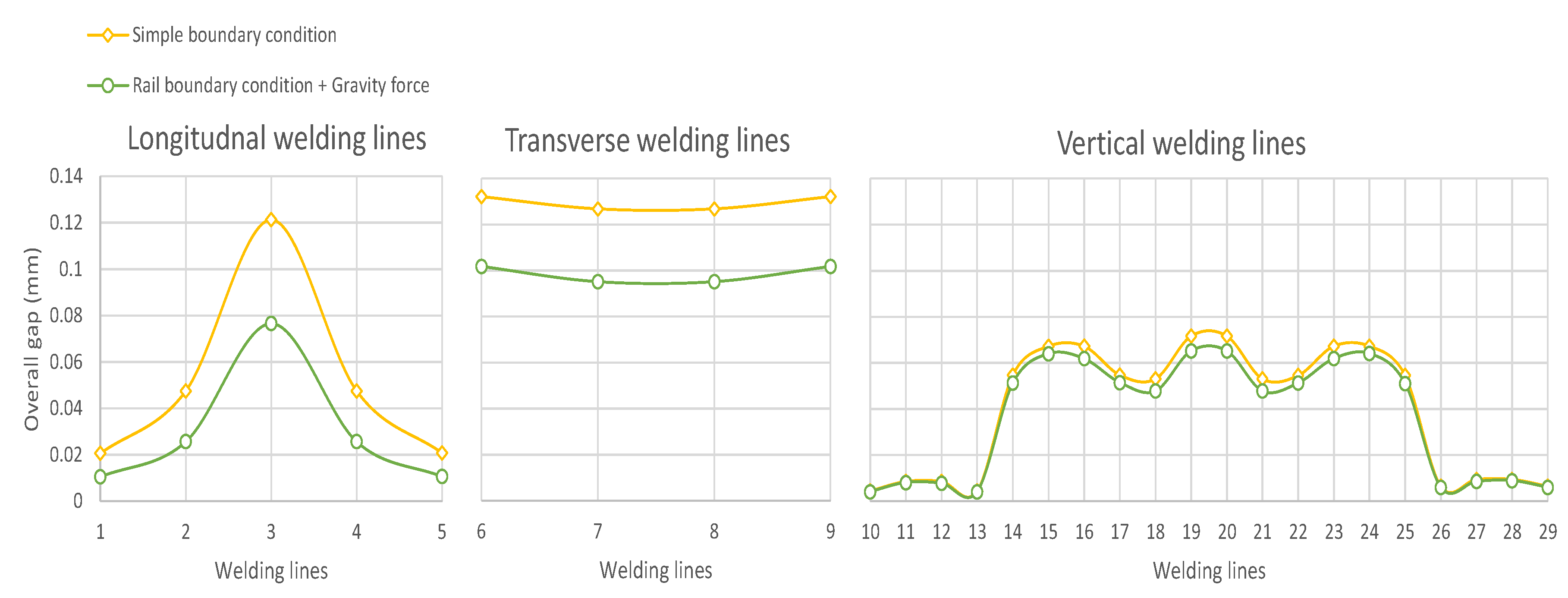
5.1. Effect of Each Welding Line on the Bottom Plate

According to [9], the gap between the stiffeners and the bottom plate is measured when all the welding lines are respectively welded alone to analyze the effect of each welding line on the structure, as presented in Figure 10. In Figure 10, the newly proposed boundary condition successfully reduces the overall gap between the stiffeners and the bottom plate by 23% and 37% at welding lines 3 and 6, which present large gaps with the simple boundary condition. The rail boundary condition highly constraints deformation of the structure because a compression force is consistently applied to the stiffeners and the bottom plate and the rails prevent the bottom plate from deforming downward. However, in Figure 10, compared to the result of the simple boundary condition, the role ratio of each welding line among all welding lines to the overall gap under the rail boundary condition has a similar tendency.

5.2. Welding Sequence

According to the method of [9] for systemically ordering the welding sequence, this study conducted 24 different welding sequences based on the data of the overall gap of each welding line, as presented in Table 3 and Table 4. Category A classifies the welding lines into horizontal and vertical by their directions, as listed in Table 3. The horizontal welding lines consist of transverse and longitudinal welding lines. Category B divides the welding lines of the horizontal lines as longitudinal and transverse welding lines for a deep analysis, as presented in Table 4. In Table 3 and Table 4, ‘H’ denotes the preference of the first order of the welding line, which leads to a high value of the gap, and ‘L’ is the opposite.

5.3. Result and Discussion of Effect of Gravity Force Under the Rail Boundary Condition on Welding Sequence

The representative reference value to discuss the effect of gravity on the numerical prediction of welding displacement of the general ship grillage structure is the z-axis distance average. It is the average of the z-axis distance of all the bottom plate nodes from the z-axis displacement average as Equation (14) to their original values as Equation (15). To compare the z-axis distribution curves of welding displacement of the bottom plate, the values of two lines such as Line T (transverse) and Line L (longitudinal) are measured, as shown in Figure 11.
Z a v e r a g e = k = 1 n z k n  
A d i s t a n c e = k = 1 n ( z k A d i s p l a c e m e n t ) n
where
Z a v e r a g e is the z-axis displacement average (mm);
A _ d i s t a n c e is the z-axis distance average (mm);
z k is the z-axis displacement of a node of a bottom plate;
n is the total number of nodes of a bottom plate;
Figure 12 shows the A _ d i s t a n c e of different welding sequences of Category A under two different boundary conditions. A _ d i s t a n c e in the simple boundary condition indicates the results of the previous paper [9]. The trend lines of A _ d i s t a n c e with different welding sequences under the two different boundary conditions show the same tendency in Figure 12. These results validate the preference of welding vertical welding lines prior to starting the horizontal welding lines (longitudinal and transverse). This is because Sequences A-5, A-6, A-7 and A-8 in Category A under the rail boundary condition with the gravity force have smaller A _ d i s t a n c e than Sequences A-1, A-2, A-3, and A-4 and the results of the simple boundary condition. First, the welded vertical lines in Sequence A-8 prior to welding horizontal lines which require the heat effect directly on the bottom plate, substantially improved the total strength of the structure. In Figure 12, comparing these values, the newly proposed boundary condition leads to approximately 37.9–54.1% reduction in A _ d i s t a n c e . Although the bottom plate and rails touch each other under the gravity force during processing of the welding sequence in the newly proposed boundary, these considerably constraint the structure and lead to the difference. The gravity force of the structure significantly mitigates the welding displacement without additional clamps for the restriction of its movement.
Figure 13 shows the A_distance of different welding sequences of Category B under two different boundary conditions. The trend lines of A_distance with different welding sequences under the two different boundary conditions show a similar tendency in Figure 13. As in Figure 12, the rail boundary condition results in 58.7–67.4% reduction in A_distance of the welding sequences of Category B. Category B-10 has the lowest A_distance, 0.38 mm and 0.19 mm respectively under the two different boundary condition. The priority for a weld sequence between the longitudinal and the transverse welding lines, the welding group of the transverse welding lines that produce a relatively higher gap prior to the longitudinal welding lines are beneficial in mitigating distortion. Additionally, in view of the trend lines of A_distance of Category B, the relative efficiency for the reduction of welding displacements of each welding sequence under both boundary conditions is not changed. The welding Sequences B-3, B-7, B-10, and B-14 in Category B show a relatively low A_distance. The common point of these four cases is the priority of the highest gap of transverse lines in their respective welding sequences. In terms of the preference for a welding sequence between the longitudinal and transverse welding lines after finishing vertical welding lines, these results also validate that assigning priority to the transverse welding lines which produce a relatively large overall gap prior to the longitudinal welding lines, is beneficial for mitigating the welding distortion, which is the same result as that in [9].
Figure 14 and Figure 15 show the effect of the different boundary conditions on the z-axis displacement distribution of sequence B-10 in Category B along lines T and L. In Figure 14, it is observed that the bucking in the z-axis displacement distribution along line T increase when the simple boundary condition is applied. In the rail boundary condition with the gravity force, the previous tendency of the buckling feature is highly mitigated. Although there are no additional external constraints such as a jig and clamp to the rail boundary condition with the gravity force, the z-axis displacement distribution shows a different tendency compared to the simple boundary condition.
Owing to the angular distortion of welding, the general grillage structure is buckled to the upper direction. However, in 14, which shows the welding displacement along line L with gravity force, the buckling feature is highly mitigated. In Figure 15, the effect of the rail boundary condition with the gravity force on the mitigation of the z-axis displacement distribution at the central zone is clearly shown. However, the mitigation of each end section of the z-axis displacement is not relatively distinctive compared to the mitigation of the central zone.

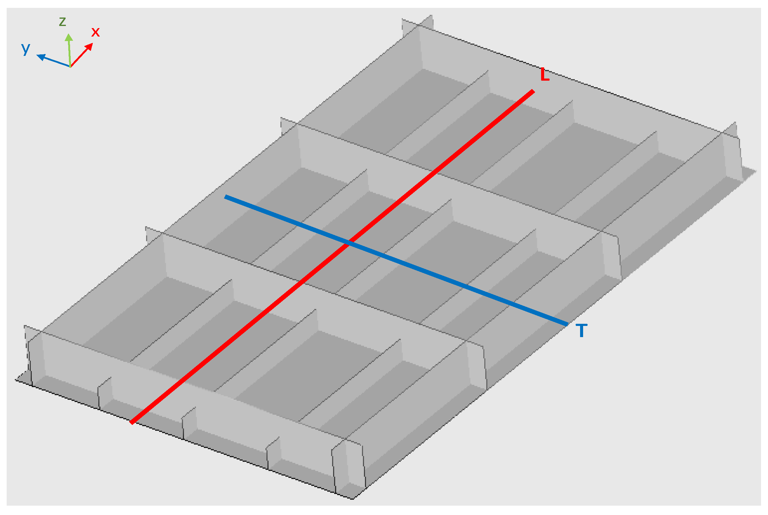
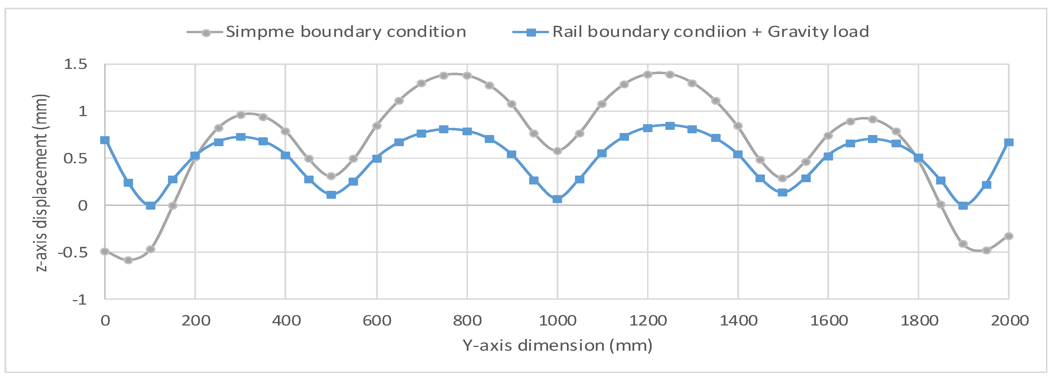
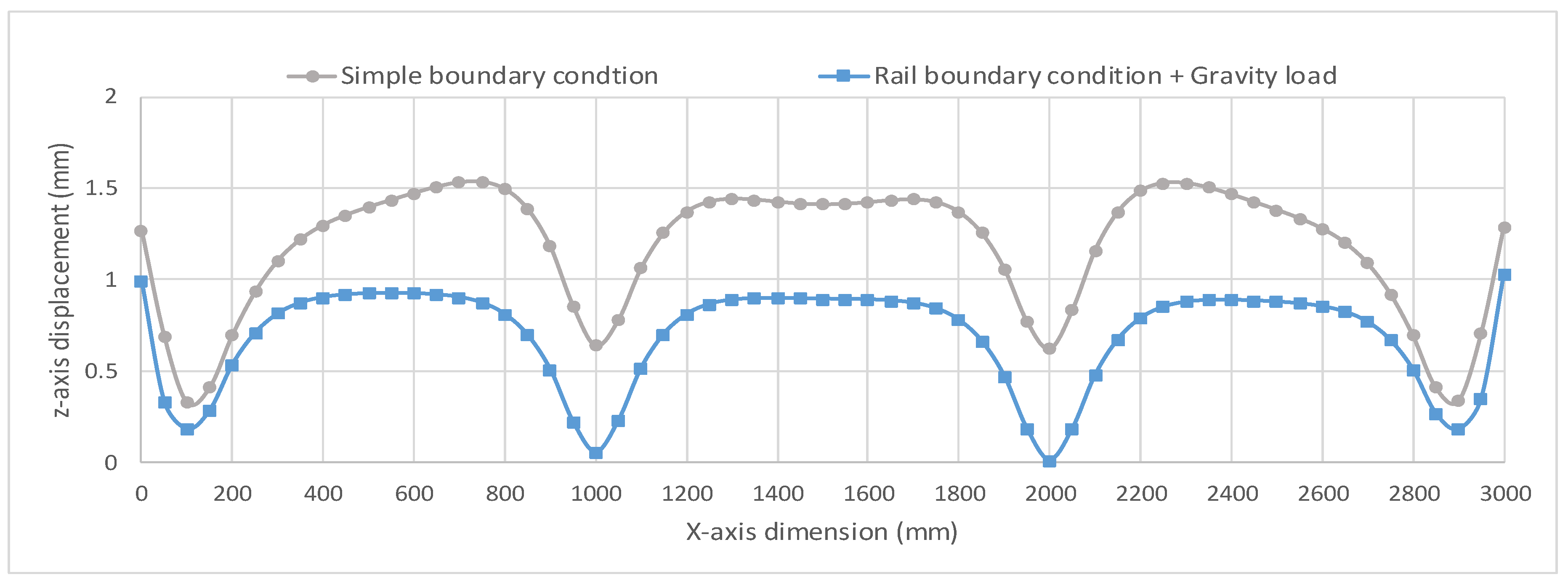
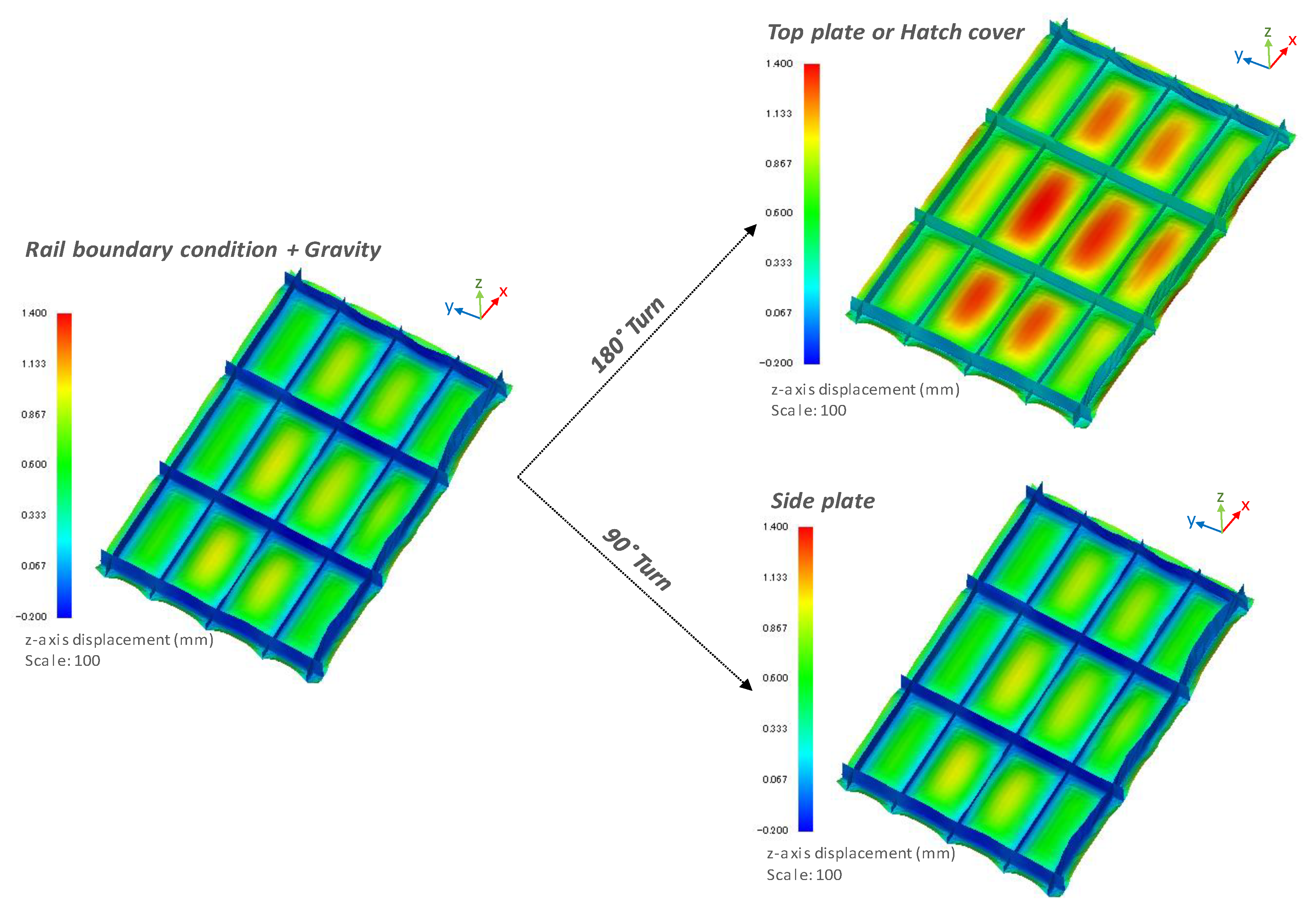
6. Effect of the Change in Gravity Direction on the Numerical Prediction of Welding Displacements

In heavy industries, several compartments are built separately before finally assembling them together according to the design plan. Generally, stiffeners are welded over the bottom plate to make the arc welding filler material flow well absorbed between the gaps of structures. Prior to assembling each compartment, the revision work for welding displacements under the final direction of the gravity is carried out, as shown in Figure 16 [16]. Thus, in the numerical prediction of welding displacements in the welding process, consideration of the change in direction of the gravity force with respect to the structure is technically essential. The present study examines the production process in heavy industries for building top and side plates. As depicted in Figure 1, turning of the general ship grillage structure by 180° and 90° after finishing welding of the stiffeners over the bottom plate for the final revision is numerically simulated. This allows validating the effect of the change in the gravity force on welding displacements. In the step of revision under the direction of the final plan, the general ship grillage structure is supposed to have simple supports at the four corners of the structure, as the simple boundary condition depicted in Figure 7, for allowing welders to revise the welding displacements under the structure.

Results and Discussion of Effect of Change in Gravity Direction on the Numerical Prediction of Welding Displacements

A d i s t a n c e as in Equation (15) is representative for discussing the effect of the change in direction of the gravity force on welding displacements. In Figure 17, A d i s t a n c e after reversing the structure by turning it 180°, is 0.212 mm, which leads to a 25.4% increase from 0.19 mm. In terms of the precise prediction of welding displacements, the value of 25.4% is not a negligible impact factor. In other words, based on the result of the numerical prediction of welding displacement without considering the change in direction of the gravity force, the prediction of the additional production cost for the revision work would have a significant error. In Figure 17, A d i s t a n c e after turning the structure 90° is 0.194 mm which leads to 2.1% increase from 0.19 mm ( A d i s t a n c e ). Compared to the case of reversing the structure, the effect of the change in gravitational orientation in the case of turning it 90° is negligibly small because the dimension of the area affected by the gravity force is greatly reduced from the whole plan of the bottom plate to the plan of the longitudinal stiffeners.
Figure 18 clearly shows the effect of reversing the general ship grillage structure on the distribution of welding displacements. In particular, the buckling feature around the central zone obviously increases. Although the stiffness of the general ship grillage structure highly increases after finishing all the welding lines, the change in the direction of the gravity force has a considerable effect on welding displacements. However, it is difficult to recognize the effect of turning the side plate 90° on the distribution of welding displacements.

7. Conclusions

In this study, the FEM approach is employed with the inherent strain, interface element, and MPC to investigate the effect of the gravity force on the numerical prediction of welding displacements. This study proposes a new approach to reflect the real work environment in the numerical simulation, i.e., the rail boundary condition using the interface element method. This research demonstrates the necessity of considering the gravity force in the numerical prediction of welding displacements for precisely predicting welding displacements in heavy industries. The conclusions of this research and suggestions are as follows:
(1)
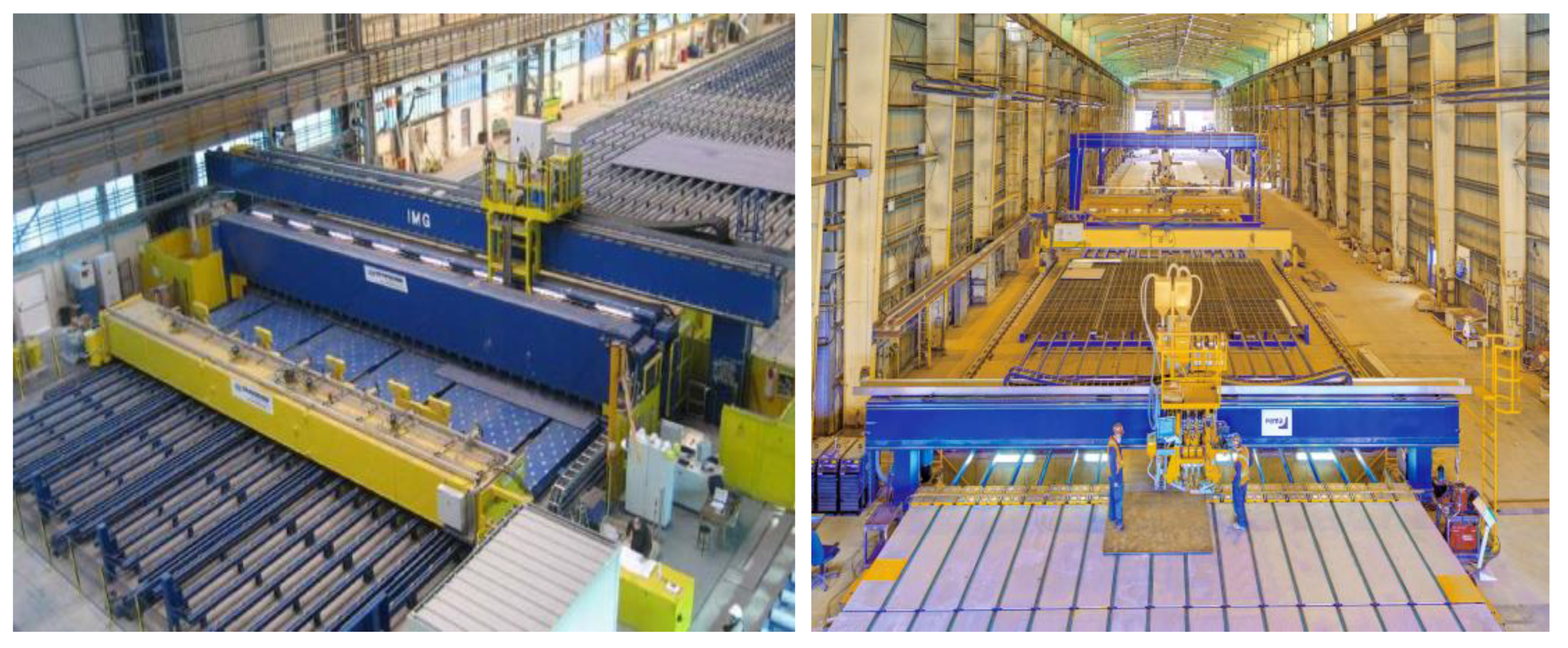
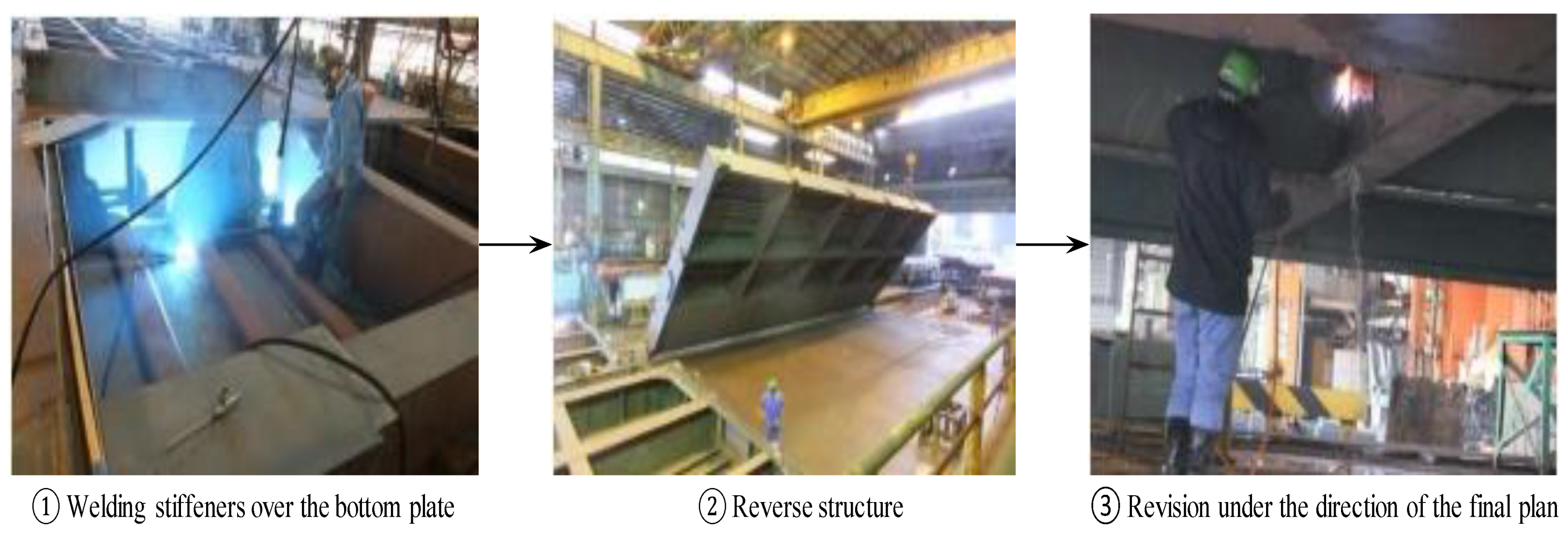
Although the bottom plate and rails touch each other under the gravity force while processing the welding sequence under the rail boundary condition, these considerably constraint the structure, and therefore, significantly mitigate the welding displacement without additional clamps for the restriction of its movement. In other words, the numerical prediction of welding displacements without precisely reflecting the real work environment would lead to enormous errors in heavy industries.
(2)
In the rail boundary condition under the effect of the gravity force, the optimal welding sequence is to weld first vertically for improving the stiffness of the structure and then horizontally. It is preferable to begin the horizontal welding lines, which generate a direct heat effect on the bottom plate, as late as possible. Moreover, welding the transverse lines before the longitudinal lines is preferred for minimizing welding displacements. The conclusion is the same as that in the previous study of D. Woo et al. (2019), which was validated according to the result of the simple boundary condition.
(3)
The change in direction of the gravity force according to the design plan has significant effects on the change in the distribution of welding displacements. Without consideration of these effects, the prediction of the additional production cost for the revision work could involve a substantial error. Thus, in the numerical prediction of welding displacements in the welding process, consideration of the change in direction of the gravity force with respect the structure is technically essential.

Author Contributions

Conceptualization, data curation, investigation, methodology, validation, writing—original draft, writing—review and editing, supervision: M.K.; Conceptualization, software, data Curation, investigation, writing—Original Draft: D.W. All authors have read and agreed to the published version of the manuscript.

Funding

This research received no external funding.

Acknowledgments

In-house developed code based on the finite element elastic method using Visual Studio was used for the calculation.

Conflicts of Interest

The authors declare no conflict of interest.

References

  1. Ueda, Y.; Yuan, M.G.; Mochizuki, M.; Umezawa, S.; Enomoto, K. Experimental verification of a method for prediction of welding residual stresses in T joints using inherent strains 4th report: Method for prediction using source of residual stress. Weld. Int. 1993, 11, 327–333. [Google Scholar] [CrossRef]
  2. Luo, Y.; Murakawa, H.; Ueda, Y. Prediction of welding deformation and residual stress by elastic FEM based on inherent strain (Report I). Trans. JWRI 1997, 182, 783–793. [Google Scholar]
  3. Deng, D.; Murakawa, H.; Ueda, Y. Theoretical prediction of welding distortion considering positioning and gap between parts. Int. J. Offshore Polar Eng. 2004, 30, 89–96. [Google Scholar]
  4. Deng, D.; Murakawa, H.; Liang, W. Numerical simulation of welding distortion in large structures. Comput. Methods Appl. Mech. Eng. 2007, 196, 4613–4627. [Google Scholar] [CrossRef]
  5. Deng, D.; Murakawa, H. Prediction of welding distortion and residual stress in a thin plate butt-welded joint. Comput. Mater. Sci. 2008, 43, 353–365. [Google Scholar] [CrossRef]
  6. Ueda, Y.; Yuan, M.G. Prediction of residual stresses in butt welded plates using inherent strains. J. Eng. Mater. Technol. 2008, 115, 417–423. [Google Scholar] [CrossRef]
  7. Shadkam, S.; Ranjbarnodeh, E.; Iranmanesh, M. Effect of sequence and stiffener shape on welding distortion of stiffened panel. J. Constr. Steel Res. 2018, 149, 41–52. [Google Scholar] [CrossRef]
  8. Liang, W.; Deng, D. Influences of heat input, welding sequence and external restraint on twisting distortion in an asymmetrical curved stiffened panel. Adv. Eng. Softw. 2018, 115, 439–451. [Google Scholar] [CrossRef]
  9. Woo, D.; Kitamura, M.; Takezawa, A. Method to systemically order welding sequence to efficiently mitigate welding displacement of a general ship grillage structure. Ships Offshore Struct. 2019. [Google Scholar] [CrossRef]
  10. Woo, D.; Kitamura, M.; Takezawa, A. Systematic method for positioning clamps and strongbacks based on their influence on welding displacements. Ocean Eng. 2020, 202. [Google Scholar] [CrossRef]
  11. Murakawa, H.; Deng, D.; Ma, N.; Wang, J. Applications of inherent strain and interface element to simulation of welding deformation in thin plate structures. Comput. Mater. Sci. 2012, 51, 43–52. [Google Scholar] [CrossRef]
  12. Japan Shipbuilding Research Association. Japan Shipbuilding Research Association Research Subcommittee: Research on Advanced Machine Accuracy Management Technology (Total Joint Report); SR237; Japan Shipbuilding Research Association: Tokyo, Japan, 2000; pp. 65–75. [Google Scholar]
  13. Kunihiko, S.; Terasaki, T. Effect of welding conditions on residual stresses distributions in welded structures materials. J. JAPAN Weld. Soc. 1976, 45, 150–156. [Google Scholar]
  14. White, J.D.; Leggatt, R.H.; Dwight, J.B. Weld shrinkage prediction. Weld. Met. Fabr. 1980, 9, 587–596. [Google Scholar]
  15. PEMA Welding Automation Company. Available online: https://pemamek.com/case/seaspans-vancouver-shipyard-selects-pema-welding-automation-solutions/ (accessed on 15 June 2019).
  16. Abe, R. A study on the accuracy control and measurement of hull structure using 3D Measurement Technique. Ph.D. Thesis, Hiroshima University, Hiroshima, Japan, March 2017. [Google Scholar]
Figure 1. Change in the gravitational orientation of welded structures.
Jmse 08 00454 g001
Figure 2. Application of inherent strain along welding line.
Jmse 08 00454 g002
Figure 3. Concept of interface element.
Jmse 08 00454 g003
Figure 4. Application of multipoint constraint function.
Jmse 08 00454 g004
Figure 5. MPC physical explanation (Attaching two plane plate, 500 mm × 250 mm).
Jmse 08 00454 g005
Figure 6. General ship grillage structure.
Jmse 08 00454 g006
Figure 7. Effect of gravity force on the bottom plate under the simple boundary condition.
Jmse 08 00454 g007
Figure 8. Welding work environment in heavy industries.
Jmse 08 00454 g008
Figure 9. Effect of gravity on the bottom plate under the rail boundary condition.
Jmse 08 00454 g009
Figure 10. Total gap between the welding lines and plate, after welding each line.
Jmse 08 00454 g010
Figure 11. Measuring lines for the z-axis displacement distribution.
Jmse 08 00454 g011
Figure 12. A d i s t a n c e of Category A under two different boundary condition.
Jmse 08 00454 g012
Figure 13. A d i s t a n c e of Category B under two different boundary condition.
Jmse 08 00454 g013
Figure 14. Z-axis displacement distribution along line T of Sequence B-10 under two different boundary conditions.
Jmse 08 00454 g014
Figure 15. Z-axis displacement distribution along line L of Sequence B-10 under two different boundary conditions.
Jmse 08 00454 g015
Figure 16. Welding work process of a hatch cover.
Jmse 08 00454 g016
Figure 17. A d i s t a n c e with the change in gravitational orientation.
Jmse 08 00454 g017
Figure 18. Z-axis displacement of rail boundary condition + gravitational orientation.
Jmse 08 00454 g018
Table 1. Welding conditions.
Current [A]Voltage [V]Travel Speed [mm/s]Heat EfficiencyNet Heat [J/mm2]
2302350.77500
Table 2. Mechanical properties of HT50 steel.
Density [kg/m3]Young’s Modulus [MPa]Specific Heat [J/kg/°C]Yield Stress [MPa]Poisson’s Ratio
77202.0 × 105659.44400.3
Table 3. Welding sequences of Category A.
SequenceWelding Sequence PreferenceWelding Sequence
Category AA-1HorizontalHVerticalH6→9→7→8→3→2→4→5→1→20→19→24→23→15→16→14→ 17→22→25→18→21→27→28→11→12→26→29→10→13
A-2HL6→9→7→8→3→2→4→5→1→10→13→26→29→11→12→27→ 28→18→21→22→25→14→17→15→16→23→24→19→20
A-3LH1→5→4→2→3→7→8→6→9→20→19→24→23→15→16→14→ 17→22→25→18→21→27→28→11→12→26→29→10→13
A-4LL1→5→4→2→3→7→8→6→9→10→13→26→29→11→12→27→ 28→18→21→22→25→14→17→15→16→23→24→19→20
A-5VerticalHHorizontalH20→19→24→23→15→16→14→17→22→25→18→21→27→28→11→12→26→29→10→13→6→9→7→8→3→2→4→5→1
A-6HL20→19→24→23→15→16→14→17→22→25→18→21→27→28→11→12→26→29→10→13→1→5→4→2→3→7→8→6→9
A-7LH10→13→26→29→11→12→27→28→18→21→22→25→14→17→15→16→23→24→19→20→6→9→7→8→3→2→4→5→1
A-8LL10→13→26→29→11→12→27→28→18→21→22→25→14→17→15→16→23→24→19→20→1→5→4→2→3→7→8→6→9
Table 4. Welding sequences of Category B.
SequenceWelding Sequence PreferencesWelding Sequence
Category BB-1VerticalHLongitudinalHTransverseH13→10→26→29→12→11→27→28→18→21→25→14→22→17→16→23→15→24→19→20→3→2→4→5→1→6→9→7→8
B-2HHL13→10→26→29→12→11→27→28→18→21→25→14→22→17→16→23→15→24→19→20→3→2→4→5→1→7→8→6→9
B-3HLH13→10→26→29→12→11→27→28→18→21→25→14→22→17→16→23→15→24→19→20→1→5→4→2→3→6→9→7→8
B-4HLL13→10→26→29→12→11→27→28→18→21→25→14→22→17→16→23→15→24→19→20→1→5→4→2→3→7→8→6→9
B-5LHH19→20→24→15→23→16→17→22→14→25→18→21→28→27→11→12→29→26→10→13→3→2→4→5→1→6→9→7→8
B-6LHL19→20→24→15→23→16→17→22→14→25→18→21→28→27→11→12→29→26→10→13→3→2→4→5→1→7→8→6→9
B-7LLH19→20→24→15→23→16→17→22→14→25→18→21→28→27→11→12→29→26→10→13→1→5→4→2→3→6→9→7→8
B-8LLL19→20→24→15→23→16→17→22→14→25→18→21→28→27→11→12→29→26→10→13→1→5→4→2→3→7→8→6→9
B-9VerticalHTransverseHLongitudinalH13→10→26→29→12→11→27→28→18→21→25→14→22→17→16→23→15→24→19→20→6→9→7→8→3→2→4→5→1
B-10HHL13→10→26→29→12→11→27→28→18→21→25→14→22→17→16→23→15→24→19→20→6→9→7→8→1→5→4→2→3
B-11HLH13→10→26→29→12→11→27→28→18→21→25→14→22→17→16→23→15→24→19→20→7→8→6→9→3→2→4→5→1
B-12HLL13→10→26→29→12→11→27→28→18→21→25→14→22→17→16→23→15→24→19→20→7→8→6→9→1→5→4→2→3
B-13LHH19→20→24→15→23→16→17→22→14→25→18→21→28→27→11→12→29→26→10→13→6→9→7→8→3→2→4→5→1
B-14LHL19→20→24→15→23→16→17→22→14→25→18→21→28→27→11→12→29→26→10→13→6→9→7→8→1→5→4→2→3
B-15LLH19→20→24→15→23→16→17→22→14→25→18→21→28→27→11→12→29→26→10→13→7→8→6→9→3→2→4→5→1
B-16LLL19→20→24→15→23→16→17→22→14→25→18→21→28→27→11→12→29→26→10→13→7→8→6→9→3→2→4→5→1

