Article

Rudder Roll Stabilization Based on Arc Tangent Nonlinear Feedback for Ships

Navigation College, Dalian Maritime University, Dalian 116026, China
*
Author to whom correspondence should be addressed.
J. Mar. Sci. Eng. 2020, 8(4), 245; https://doi.org/10.3390/jmse8040245
Submission received: 10 March 2020 / Revised: 26 March 2020 / Accepted: 27 March 2020 / Published: 2 April 2020

Abstract

:
The rudder is used for damping the roll motion of a ship. Study of this motion is the essence of this paper. The responses of yaw and roll motions are different as the rudder angle varies. The low frequency motion of the rudder mainly affects the ship’s yaw motion, whereas the high frequency motion of the rudder mainly affects the roll motion. As long as the controller is well designed, the characteristic of the rudder can be used to reduce the roll motion. In order to save energy and reduce steer frequency, a nonlinear feedback controller is proposed based on the arc tangent function processing feedback error to save energy consumption. In addition, a ZOH component is applied in the system to reduce the steer frequency. In heavy sea state, simulation results illustrate that controllers based on pole assignment with and without nonlinear feedback can reduce roll motion by 32.1% and 30.3%, respectively, when the rudder turn rate is limited within 7°/s. Furthermore, the former reduces the amplitude of rudder angle by 23.3% compared with the latter, which means the nonlinear feedback control consumes less energy. Consequently, the ZOH can lower steer frequency to once every 1 s, which protects steering gear from abrasion.

1. Introduction

Roll motion will inevitably occur when a ship is sailing in rough seas. Violent roll motion endangers the comfort of crew and passengers onboard and the safety of the ship as well. In light of reducing the rolling motion of an ocean-going ship, a number of global researchers in this field have studied the roll damping facilities and carried out relevant experiments where appropriate. Alujevic et al. [1] presented a U-tube anti-roll tank to absorb the wave power to reduce the roll motion. Marzouk et al. [2] analyzed the differences of passive and active anti-roll tanks and gave the conclusion that the performances of active anti-roll tanks were better than passive anti-roll tanks. Irkal et al. [3] researched the effect of bilge keel on roll damping and analyzed the influences of ship type on performances of bilge keel. Hickey et al. [4] transferred the rolling model of a ship to a second order transfer function and used H∞ theory to design controllers for a fin stabilizer system, which laid the theoretical foundation for roll damping control. However, facilities such as fin stabilizers and anti-roll tanks occupied quite a lot space onboard a ship that were not economical, ad hoc for commercial ships. Therefore, rudder roll damping technology has prevailed as a hot topic in recent years. The neural network-based controller for ship’s roll damping in use of the rudder’s motions is also important in the development of RRD (Rudder Roll Damping). Some references also designed neural network controllers for rudder roll damping system, which greatly improved performance of roll damping [5,6,7,8,9]. Moreover, Wang et al. [10] designed a sliding mode controller for nonlinear non-minimum phase rudder roll damping system of the ship and obtained satisfactory results. Zhou et al. [11] proposed a robust H∞ controller for rudder roll damping system. It researched the selection method of weight function to restrain the disturbances and keep course precisely. These researches relied on higher rudder turn rate and steer frequency. Jin et al. [12] argued high frequency steering gear was not satisfactory on most of commercial ships. Therefore, some researchers had carried out relevant studies on the premise of lower rudder turn rate. Kapitanyuk designed an optimal controller that had a good performance when the rudder turn rate is limited within 7°/s [13]. Yet there are still three shortcomings: (1) the steer frequency was not ultimately lowered; (2) the optimal controllers were not suitable for ship control because of model perturbation; (3) it could not reduce energy consumption. For energy-saving achievement, Zhang et al. [14,15,16,17] used the nonlinear feedback algorithm to keep course and obtained satisfactory results. The nonlinear feedback control technique also testified in terms of pressure control on Liquefied Natural Gas Carrier as proposed in [18]. This paper implements nonlinear feedback algorithm to rudder roll damping system and constructs an arc tangent nonlinear feedback controller. The Zero-Order Holder (ZOH) component is applied to lower the steer frequency.
The contributions of this paper are mainly concentrated on the following points:
(1) This paper proposes a novel rudder roll-damping algorithm when the arc tangent nonlinear feedback controller is implemented. In comparison with other controllers, nonlinear feedback controller decreases the rudder angle to the same extent for being more energy-efficient with the premise of remaining performance of damping roll motion unaffected.
(2) The paper merges the ZOH component into the rudder roll damping system. Simulation results verified that the ZOH component could further lower the steer frequency of steering gear to the acceptable ranges for most commercial ships.

2. Ship Model

Considering the fact that is difficult to establish a six DOF (Degree Of Freedom) mathematical model of a ship to describe the ship motion response thoroughly, a four DOF model of a ship is therefore established when the heave and pitch motions are neglected.
{ m ( u ˙ v r x G r 2 + z G p r ) = X m ( v ˙ + u r + x G r ˙ z G p ˙ ) = Y I z r ˙ + m x G ( v ˙ + u r ) = N I x p ˙ m z G ( v ˙ + u r ) = K ρ g G M ψ
where, x G , z G are longitudinal and vertical coordinates of gravity center, respectively, m is ship tonnage, u is the longitudinal speed, v is the lateral speed, I is the inertial moment, r and p are angular velocity of yaw and roll motion, respectively, ψ is the ship course. g is the acceleration of gravity, φ is the roll angle of ship. ρ is density of sea water, is displacement of ship, GM is the initial metacentric height of ship, X, Y, N, K are hydrodynamic forces and moments. For acquiring a linear ship model suitable for the controller design, the Taylor series expansion is carried out around the equilibrium point and only the first order is retained. Thus, Equation (1) can be converted to
x ˙ = A x + B u = E 1 F x + E 1 G δ E = [ m Y v ˙ m x G Y r ˙ m z G Y p ˙ 0 0 m x G N v ˙ I z N r ˙ N p ˙ 0 0 m z G K v ˙ K r ˙ I x K p ˙ 0 0 0 0 0 1 0 0 0 0 0 1 ] G = [ Y δ + Δ u Y δ u N δ + Δ u N δ u K δ + Δ u K δ u 0 0 ] F = [ Y v + Δ u Y v u Y r m u Y p + Δ u Y p u Y φ 0 N v + Δ u N v u N r m x G u N p + Δ u N p u N φ 0 K v + Δ u K v u K r + m z G u K p + Δ u K p u K φ m g G M 0 0 0 1 0 0 0 1 0 0 0 ]
where x = [ v , r , p , φ , ψ ] T is the state vector, A = E 1 F is the system matrix, B = E 1 G is the input matrix, δ is rudder angle. Y, N and K with subscripts are first order Taylor series expansion coefficients of hydrodynamic forces and moments mentioned in Equation (2) [19]. For the convenience of designing controllers, Equation (2) can be converted to transfer functions [20].
v ( s ) = K d v 1 + T v s δ ( s )
φ ( s ) = ω n 2 s 2 + 2 ξ n ω n s + ω n 2 [ K δ p δ ( s ) + K v p v ( s ) + w φ ( s ) ]
ψ ( s ) = 1 ( 1 + T r s ) s [ K δ r δ ( s ) + K v r v ( s ) + w ψ ( s ) ]
where w φ ( s ) , w ψ ( s ) are disturbances of environment to roll and yaw motions of ship respectively. The parameters of Equation (3) are given in Table 1 [13].

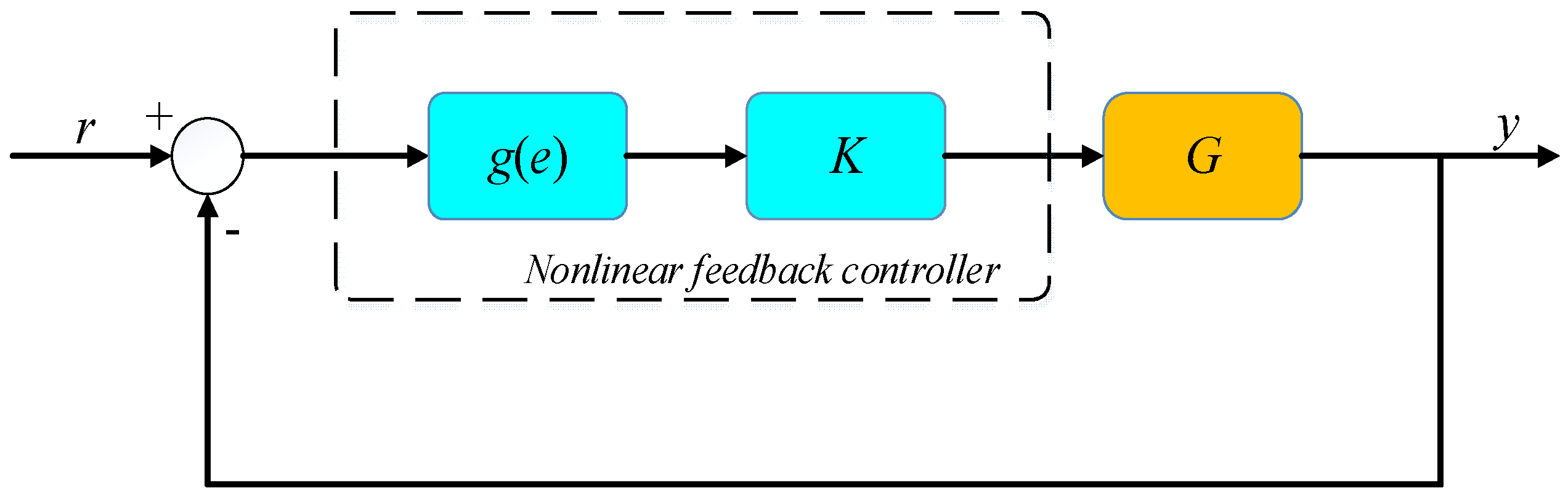
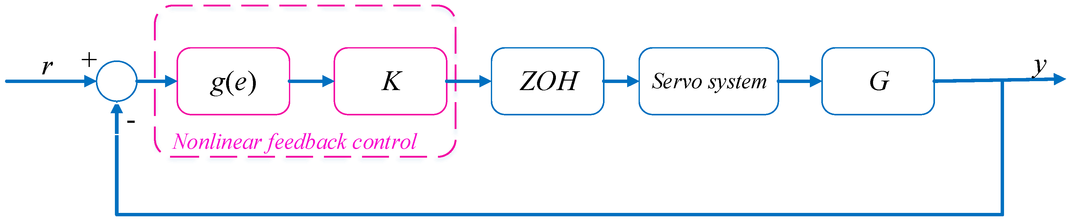
3. Controller Design

The theoretical design of nonlinear feedback control is illustrated in Figure 1 and will be further elaborated in simulation thereafter. To be more explicit, K is the original controller, g(e) is the nonlinear function, G is the controlled plant. In this paper, K is designed based on pole assignment, i.e., g ( e ) = arctan ( ω e ) , (ω = 0.5).
Due primarily to the fact that roll and yaw motions are assumed to be without coupling when the controller is designed, the robustness of the controller should be further verified since the controlled plant is the MMG (Maneuvering Modeling Group) model, for which coupling between roll and yaw motion actually exists.

3.1. Controller Design Based on Pole Assignment

Figure 2 shows the Bode plot of the system. The band width of yaw and roll systems are different. The characteristics can be utilized to keep course and damp rolling motion by the rudder only.
As far as our main research objectives are concerned, the rudder can be divided into two parts, δ = δ y a w + δ r o l l , i.e., δ y a w is used to keep course, whereas δ r o l l is used to damp roll motion. Based on pole assignment, control rules can be described as
δ r o l l = K 1 p K 2 φ
δ y a w = K 3 r K 4 ( ψ ψ h )
where ψ h is the setting course, K i ( i = 1 , 2 , 3 , 4 ) is the gain of state vector.
For the convenience of controller design, assuming that there is no coupling between yaw and roll motions ( v = 0 ).
{ s 2 + 2 ξ n ω n s + ω n 2 = ω n 2 K d p δ r o l l ( 1 + T r s ) s = K d r δ y a w
K i ( i = 1 , 2 , 3 , 4 ) can be yielded by Equation (7).
{ 2 ξ n ω n + ω n 2 K d p K 1 = 2 ξ φ ω φ ( 1 + K d p K 2 ) ω n 2 = ω φ 2 1 + K d r K 3 T r = 2 ξ ψ ω ψ K d r K 4 T r = ω ψ 2
where ξ φ = 0.0733 , ω φ = 1.4384 , ξ ψ = 0.7507 , ω ψ = 0.4662 are natural frequencies and damping coefficients of roll and yaw systems respectively [19]. It is important to limit the band width of yaw and roll systems, which will influence the performance of controllers. In the rudder roll damping system, the dividing frequency is generally taken as
ω ψ 1 2 ξ ψ 2 + 4 ξ ψ 4 4 ξ ψ 2 + 2 < ω c < ω φ 1 2 ξ φ 2 + 4 ξ φ 4 4 ξ φ 2 + 2
where the first item is band width of yaw system, the last item is the band width of the roll system. According to the method motioned above, a controller for rudder roll damping system can be obtained.
δ = 7.91 r + 9.69 ( ψ ψ h ) + 17.22 p + 2.75 φ

3.2. Nonlinear Feedback Control

Notably, a series of experiments reveal that different types of nonlinear function can be implemented to design nonlinear feedback controllers. Undoubtedly, one of the significant features of the nonlinear feedback algorithm is to focus on decreasing the feedback error. Therefore, the arc tangent function is explored to design the controller for rudder roll damping system in order to verify the universality of nonlinear feedback algorithm. The arc tangent function can be expanded to the Taylor series when analyzing its effect in the system.
arctan ( ω e ) = ω e ω 3 3 e 3 + ω 5 5 e 5 ω 7 7 e 7 + ω 9 9 e 9
where ω is the coefficient, e is the feedback error.
For the convenience of analyzing effect of arc tangent function, the Taylor series can be retained to the first order.
g ( e ) = arctan ( ω e ) ω e
Although the arc tangent function can be processed as Equation (11), the nonlinear and linear functions still differ from each other, which are analyzed in the following section.

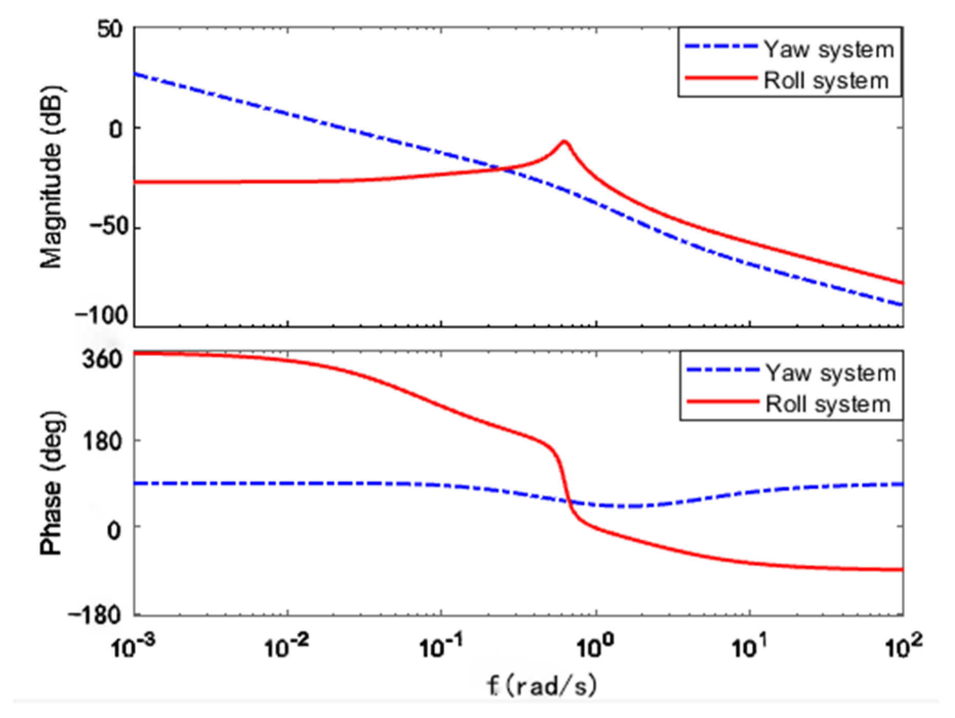
3.2.1. Effect on Stability of the System

When a ship is navigating at sea, roll motion occurs around the equilibrium point ( φ = 0 ) of the system. When the roll motion deviates from the equilibrium point, the steady heeling and even the danger of capsizing might be encountered. In this circumstance, shipboard cargoes stowage arrangement should be adjusted to offset the heeling moment while the rudder damping moment can be negligible. Therefore, relevant research should be carried out to analyze the effect of the arc tangent function on stability of the system around the equilibrium point.
Taking ship model Equation (3) as a research plant, it can be converted to its state space equation [20]. Let x = [ φ , p , v , r , ψ ] T and ignore the disturbances of environment.
{ x ˙ = A x + B u y = C x
where, A = [ 0 1 0 0 0 ω n 2 2 ξ ω n ω n 2 K v p 0 0 0 0 1 / T v 0 0 0 0 K v r / T r 1 / T r 0 0 0 0 1 0 ] , B = [ 0 ω n 2 K d p K d v / T v K d r / T r 0 ] , C = [ 1   0   0   0   0 0   0   0   0   1 ] .
Considering the controlled input, it can be expressed as
{ x ˙ = A x + B [ 2.75 ω   17 . 22 ω   0   7 . 91 ω   9 . 69 ω ] x + B ψ h y = C x
where ψ h is setting course. Convert Equation (13) into the standard form
{ x ˙ = A x + B u y = C x
where, A = [ 0 1 0 0 0 ω n 2 + 2.75 ω ω n 2 K d p 2 ξ ω n + 17 . 22 ω ω n 2 K d p ω n K v p 7 . 91 ω ω n 2 K d p 9 . 69 ω ω n 2 K d p 2 . 75 ω K d v / T v 17 . 22 ω K d v / T v 1 / T v 7 . 91 ω K d v / T v 9 . 69 ω K d v / T v 2.75 ω K d r / T r 17 . 22 ω K d r / T r K v p / T r 1 / T r   + 7 . 91 ω K d r / T r 9 . 69 ω K d r / T r 0 0 0 1 0 ] , B = [ 0 ω n 2 K d p K d v / T v K d r / T r 0 ] T .
Thus, as long as x ˙ = A x is asymptotic stable around equilibrium point, the arc tangent function has no effect on the stability of system.
Lemma 1.
[21]: the necessary and sufficient conditions for the system to be asymptotically stable are based on the premise of a real symmetric positive definite matrix Q is given. There is a real symmetric matrix P, which is satisfied in A T P + P A = Q . The system is stable around the equilibrium point (x = 0) when P is the positive definite matrix.
Lemma 2.
[21]: if P is a real symmetric matrix, it is a positive definite matrix when the sequential principal minors are all greater than zero.
Let Q = I. Because of A T P + P A = Q , P can be calculated as
P = [ 33 . 2271 0 . 5000 8 . 1911 3 . 4101 31 . 1077 0 . 5000 3 . 6323 1 . 7781 1 . 2507 3 . 4101 8 . 1911 1 . 7781 5 . 2548 2 . 3176 2 . 9174 3 . 4101 1 . 2507 2 . 3176 2 . 1855 0 . 5000 31 . 1077 3 . 4101 2 . 9174 0 . 5000 56 . 7438 ]
Let Pi (i = 1, 2, 3, 4, 5) be a sequential principal minor. P1 = 33.2271, P2 = 120.4393, P3 = 269.56, P4 = 292.78, P5 = 0.005. As a result, equation (14) is asymptotically stable around the equilibrium point. It is proved that the arc tangent function has no influence on the stability of the system.

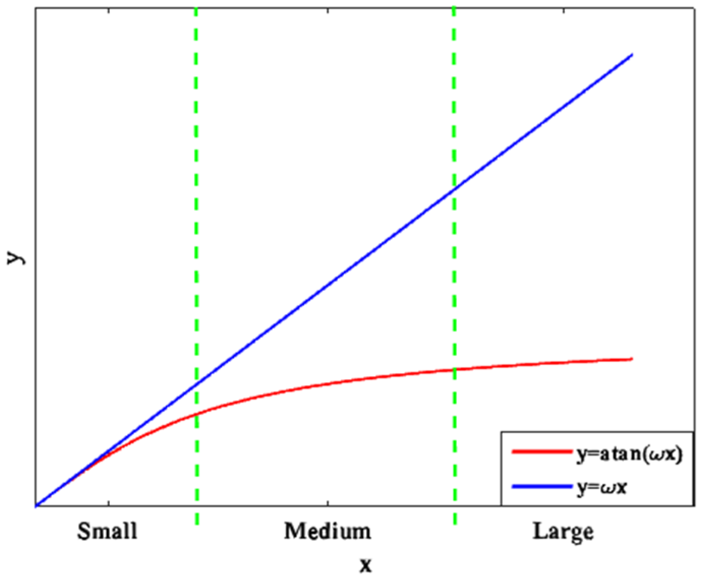
3.2.2. Differences of Nonlinear and Linear Function

Equation (13) illustrates that the arc tangent and linear function can reduce the gain of the controller. However, there are still some differences between them. As shown in Figure 3, in the small zone, the effect of arc tangent function is nearly consistent with that of the linear feedback. In the Medium zone, the arc tangent function tends to be maximum, which can reduce the amplitude of the rudder angle given by the controller due to its inertia and nonlinear factors. The ultimate objective of energy saving is therefore achieved. The feedback error of the system pertains to the medium zone, especially when the ship sails in rough seas. Hence, the nonlinear feedback is better than the linear feedback in the medium zone. In the large zone, the arc tangent function reaches its maximum so that the nonlinear feedback algorithm is not suitable anymore. In addition, Reference [14] also analyzed the differences of nonlinear feedback and linear feedback.

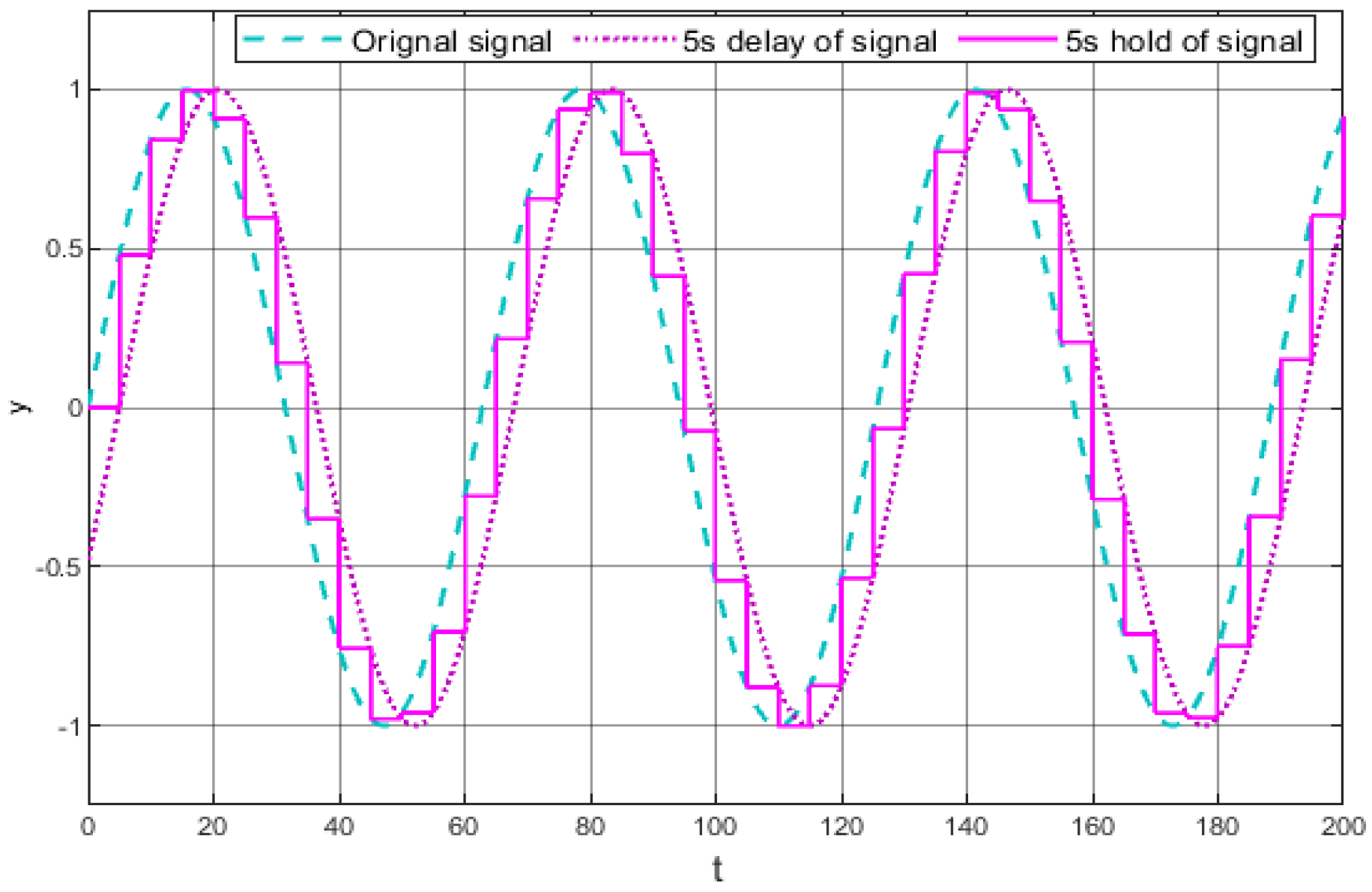
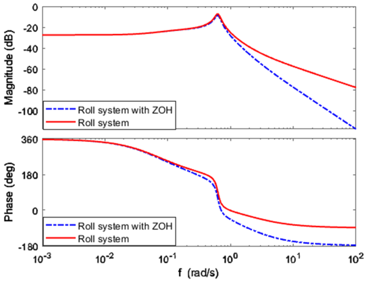
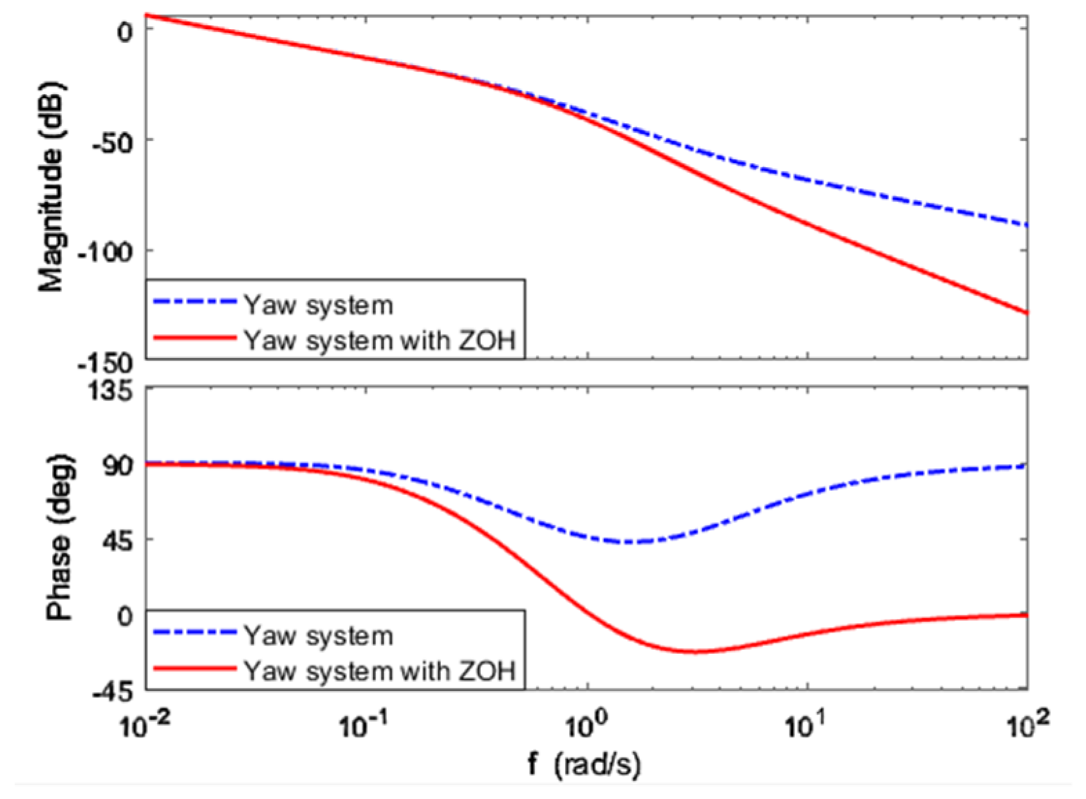
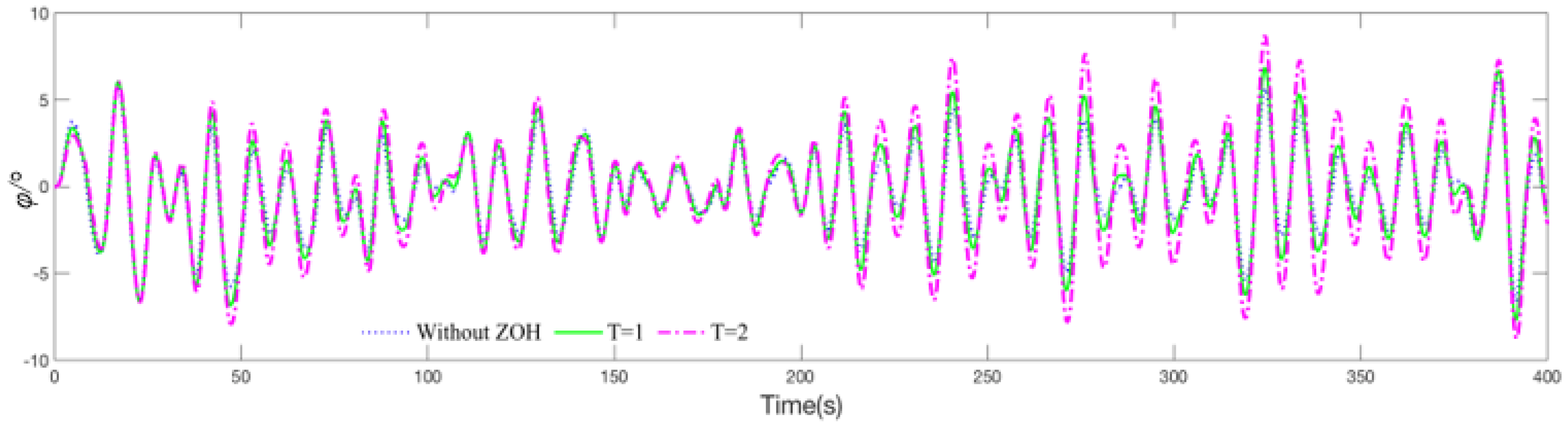
3.2.3. ZOH Component for Lowering Steer Frequency

For reducing steer frequency to protect steering gear from abrasion, a ZOH component is introduced into the rudder roll damping system. Reference [22] analyzed the effect of time delay on characteristics of steering gear. Thereby, the effect of the ZOH component on rudder roll damping system will be analyzed in detail.
(1) ZOH component
As shown in Figure 4, ZOH is used to resample the signal after the sampled signal has been held for a period. After implementing the ZOH on rudder roll damping system, the steer frequency can be adjusted to the accepted ranges through regulating the hold time of ZOH. Equation (15) is the mathematical description of ZOH.
e ( n T + Δ t ) = e ( n T )
where T is the hold time of ZOH, n=1,2,3…, Δ t is the wave period.
In the field of rudder roll damping control, it is important to select an appropriate steer frequency. Otherwise, if the steer frequency is higher, the steering gear will suffer from abrasion. In contrast, if the lower steer frequency is ensured, the roll damping performance of the rudder will be worse. Furthermore, the maximal slew rate of steering gear is used when ZOH is employed to reduce the steering frequency. In accordance with the analysis of ship test data, the rudder is steered once every 8–10 s manually while the autopilot steers the rudder once every 4–6 s. When the rudder is used to damp roll motion and keep course simultaneously, the recommended steer frequency is once every 0.5–2 s. The simulations discussed below elaborate on the specific analysis.
(2) Effect of ZOH component on stability of system
The structure of the model with ZOH is shown in Figure 5. The transfer function of ZOH is
G h ( s ) = 1 e T s s
Expanding the equation (16) and retaining to the first order
G h ( s ) = 1 e T s s = 1 s ( 1 1 e T s ) T 1 + T s
Hence, transfer functions of ship model with ZOH component are
G φ ( s ) = T 1 + T s · ω n 2 s 2 + 2 ξ ω n s + ω n 2 ( K δ p + K v p K d v 1 + T v s )
G ψ ( s ) = T 1 + T s · 1 ( 1 + T r s ) s ( K δ r + K v r K d v 1 + T v s )
Close loop transfer function of roll system can be described by Equation (19)
Φ φ ( s ) = T [ ω n 2 K δ p ( 1 + T v s ) + K v p K d v ] ( 1 + T s ) ( s 2 + 2 ξ ω n s + ω n 2 ) ( 1 + T v s ) + T [ ω n 2 K δ p ( 1 + T v s ) + K v p K d v ]
Equation (20) is the characteristic polynomial of close loop transfer function
T · T v s 4 + ( T + T v + 2 ξ T · T v ω n ) s 3 + ( T · T v ω n 2 + 2 ξ ( T + T v ) ω n + 1 ) s 2 + ( 2 ξ ω n + ω n 2 ( T + T v ) + K d p T · T v ω n 2 ) s + T ( K d p ω n 2 + K d p K v p ) + ω n 2 = 0
Lemma 3.
(Hurwitz stability criterion): The characteristic polynomial of system is D ( s ) = a 0 s n + a 1 s n 1 + + a n 1 s + a n . If n = 4, the necessary and sufficient conditions for the stability of system are: (1) The coefficients of characteristic polynomial are all positive; (2) Δ 2 = a 1 a 2 a 0 a 3 > 0 and Δ 2 > a 1 2 a 4 / a 3 .
According to lemma 3, the T must be greater than −0.02. In ZOH component, T is the hold time and greater than zero. Therefore, the ZOH component does not affect the stability of the roll system.
Similarly, it is simple to prove that the ZOH component has no influence on the stability of the yaw system.
(3) Effect of ZOH component on system performance
The Bode plot of roll and yaw system of the ship are shown in Figure 6 and Figure 7, respectively. For damping roll motion by rudder, the rudder must be steered at a higher frequency. The ZOH component can increase the slope of high frequency asymptote and accelerate the attenuation of high frequency interference to lower the steer frequency. For keeping course, the rudder works at a lower frequency. The ZOH component has little influences on the yaw system. It can also lower the steer frequency when the rudder is used to damp roll motion of ship.

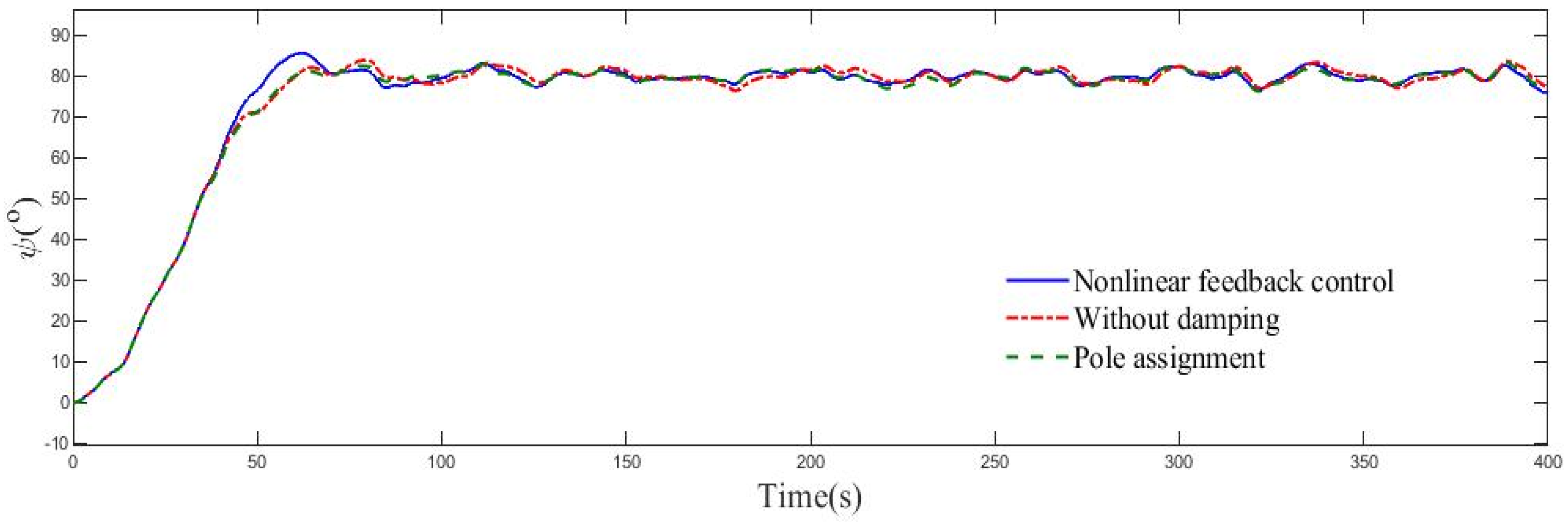
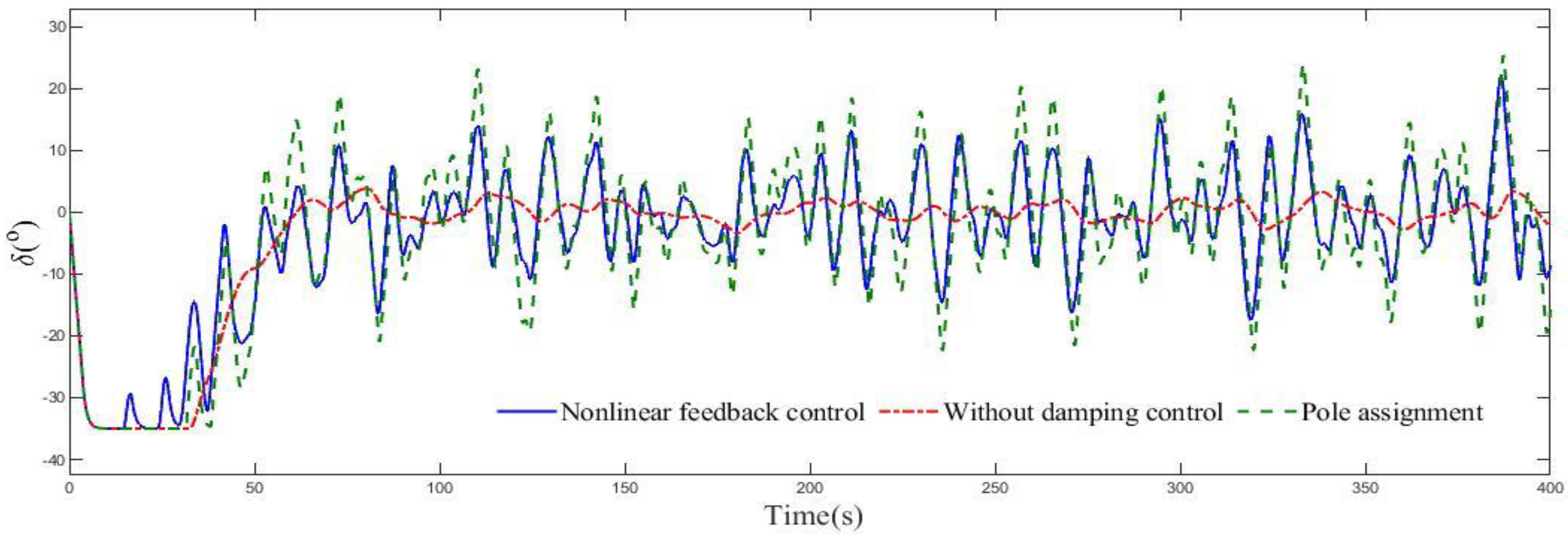
4. Simulation and Analysis

The simulation diagram of rudder roll damping system is shown as Figure 8. Assuming the ship sails at heavy sea state, wave disturbance is simulated by the second order transfer function which is driven by white noise. It is the average influence of wave disturbance [19]. The transfer function of very high seas is h ( s ) = 1.5244 s s 2 + 0.4042 s + 0.1634 . Moreover, in order to compare the performance of controllers, the damping ratio is determined as
R e d u c a t i o n = S D S D R D S D × 100 %
where SD and SDRD are the standard deviation of roll motion with and without roll damping controller separately.
Furthermore, the rudder turn rate and limit of servo system in Figure 8 are set up as 7°/s and 35° respectively which can be satisfied on most commercial ships.

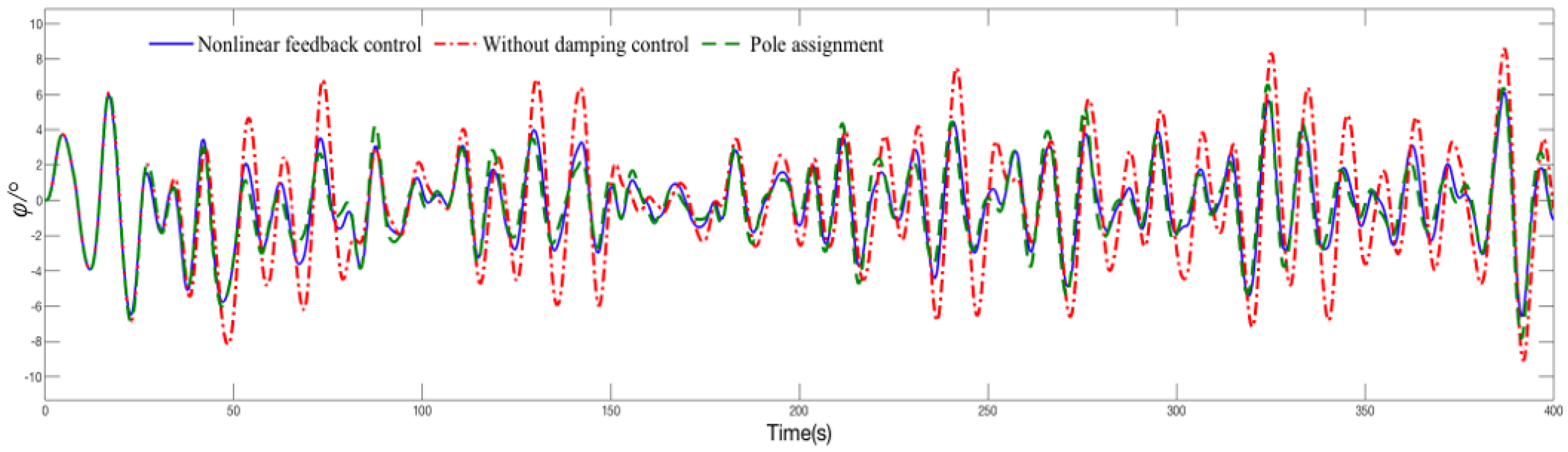
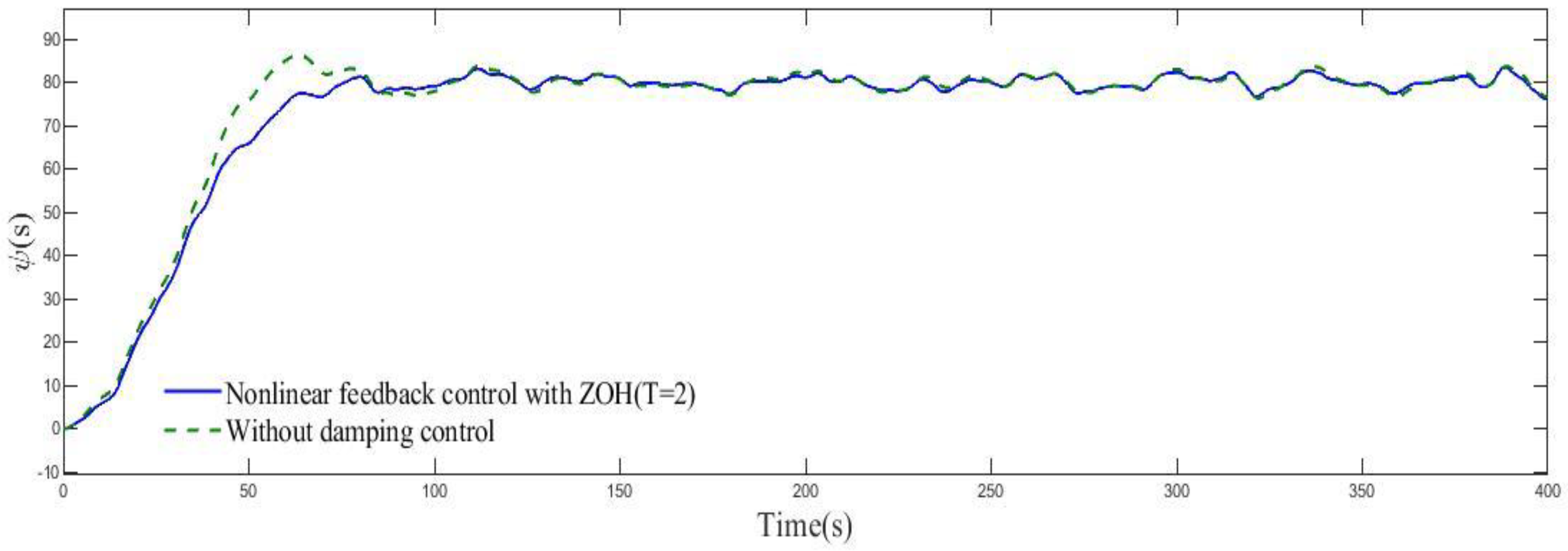
4.1. Performance of the Controller

For illustrating the performance of nonlinear feedback controller, the rudder roll damping system is simulated.
As shown in Figure 9, “original control” means that the controller is designed by pole assignment. “Without damping control” means that there is no controller for roll damping. The damping ratio of original control and nonlinear feedback control are 30.3% and 32.1% respectively. The mean rudder angle under original control and nonlinear feedback control are 10.1° and 7.75° respectively. The amplitude of average rudder angle has been reduced by 23.3% under the nonlinear feedback control compared with that of the original control, which means that the energy consumption of steering gear is reduced. Figure 10 illustrates that the roll damping controllers have no significant effect on course keeping, which explains that the dividing frequency of yaw and roll systems is appropriately ensured. Figure 11 shows that the nonlinear feedback controller can reduce the rudder angle when roll motion of ship is damping.
Additionally, for reducing the steer frequency, the ZOH component is introduced into the rudder roll damping system.

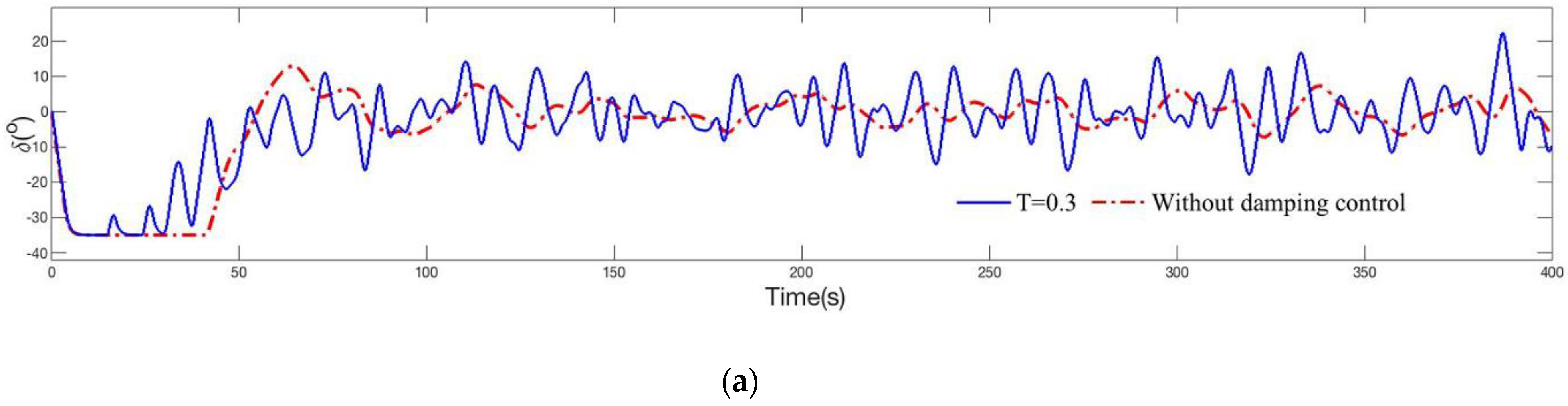
4.2. Effect of Hold Time of ZOH on System

In this part, the controller remains unchanged, while the hold times of the ZOH component are taken as 0.3 s, 0.5 s, 1 s, 1.5 s, 2 s separately to analyze the effect of hold time of the ZOH component to roll damping. As shown in Figure 12, poor performance of steering gear is caused by overlong hold time of ZOH. ZOH will hold the rudder angle for a period of time (T). It could reduce the steering frequency. With the increase of hold time of ZOH, the steer frequency decreases gradually, while the damping ratio is also decreasing. Figure 13 shows that the effect of roll motion damping of the controller is worse when the hold time of ZOH is larger. However, as shown in Figure 14, the performance of course keeping is still acceptable when the hold time of ZOH is taken as 2 s, which proves that steer frequency for course keeping can be lowered greatly. For more specific analysis, Table 2 gives the data of the experiments as aforementioned.
Damping ratio can be kept on at a higher level when the rudder is steered once every 1 s. Lower steer frequency makes the damping ratio decrease substantially. Experiments demonstrate that the higher damping ratio must be premised at a higher steer frequency. This paper recommends taking steer frequency as once every 1 s to get higher damping ratio and simultaneously protect the steering gear from abrasion.

5. Conclusions

This paper solves two problems of roll stabilization for ships which are energy saving and lowering of steer frequency. The arc tangent nonlinear feedback algorithm is implemented on the rudder roll damping system, which reduces the amplitude of rudder angle to save energy. Additionally, ZOH component is applied to lower the steer frequency and protect the steering gear from abrasion. The core of the algorithm is that a nonlinear feedback function is used instead of a linear feedback function and the existing controller can be used with this algorithm for smaller output of steering gear. Experiments illustrate that the nonlinear feedback control has great advantages on the rudder roll damping control. Nevertheless, the relevant study can be set as an optimization problem for carrying out further research, which will be addressed in our future work plan.

Author Contributions

Visualization, J.Z. and C.L. Resources, J.Z. and C.L. Validation, J.Z. Writing—review & editing, J.Z. Methodology, J.Z. and X.Z. Supervision, X.Z. All authors have read and agreed to the published version of the manuscript.

Funding

This work is partially supported by the National Natural Science Foundation of China (Grant No. 51679024), the Fundamental Research Funds for the Central University (Grant No. 3132016315), and the University 111 Project of China (Grant No. B08046).

Acknowledgments

We appreciate all editors and reviewers for the valuable suggestions and constructive comments. Thank you to everyone who contributed to this article.

Conflicts of Interest

The authors declare no conflict of interests.

References

  1. Alujevic, N.; Catipovic, I.; Malenica, S.; Senjanovic, I.; Vladimir, N. Ship roll control and power absorption using a U-tube anti-roll tank. Ocean Eng. 2019, 172, 857–870. [Google Scholar] [CrossRef]
  2. Marzouk, O.A.; Nayfeh, A.H. Control of ship roll using passive and active anti-roll tanks. Ocean Eng. 2009, 36, 661–671. [Google Scholar] [CrossRef]
  3. Irkal, M.A.R.; Nallayaraus, S.; Bhattacharyya, S.K. Numerical prediction of roll damping of ships with and without bilge keel. Ocean Eng. 2019, 179, 226–245. [Google Scholar] [CrossRef]
  4. Hickey, N.A.; Grimble, M.J.; Johnson, M.A.; Katebi, M.R.; Melville, R. Robust fin roll stabilisation of surface ships. In Proceedings of the 36th IEEE Conference on Decision and Control, San Diego, CA, USA, 10–12 December 1997. [Google Scholar]
  5. Awad, T.M.; Elgohary, A.; Mohamed, T.E. Ship roll damping via direct inverse neural network control system. Alex. Eng. J. 2018, 57, 2951–2960. [Google Scholar] [CrossRef]
  6. Wang, Y.; Nguyen, H.D. Rudder Roll Damping Autopilot Using Dual Extended Kalman Filter Trained Neural Networks for Ship in Waves. J. Mar. Sci. Appl. 2019, 18, 510–521. [Google Scholar] [CrossRef]
  7. Wang, Y.; Chai, S.; Khan, F.; Nguyen, H. Unscented Kalman Filter trained neural networks based rudder roll stabilization system for the ship in waves. Appl. Ocean Res. 2017, 68, 26–38. [Google Scholar] [CrossRef]
  8. Wang, Y.; Nguyen, H.D.; Chai, S. Radial basis function neural network based rudder roll stabilization for ship sailing in waves. In Proceedings of the 2015 5th Australian Control Conference (AUCC 2015), Gold Coast, Australia, 5–6 November 2015. [Google Scholar]
  9. Nguyen, P.; Jung, Y. Neural Network Based Rudder-Roll Damping Control System for Ship. J. Korean Navig. Port Res. 2007, 31, 289–293. [Google Scholar] [CrossRef]
  10. Wang, S.K.; Jin, H.Z. Nonlinear non-minimum phase rudder-roll damping systems of ship using sliding mode control. Comput. Eng. Appl. 2018, 54, 207–212. [Google Scholar]
  11. Zhou, L.M.; Wang, Y.L. Robust H∞ Control of Rudder Roll Damping for Ships. Control Eng. Chin. 2016, 23, 102–108. [Google Scholar]
  12. Jin, H.Z.; Pan, L.X.; Wang, L.L. Modified variable structure control in rudder roll damping of submarine near free-surface. J. Harbin Inst. Technol. 2019, 42, 1462–1466. [Google Scholar]
  13. Kapitanyuk, Y.A.; Proskurnikov, A.V.; Cao, M. Optimal controllers for rudder roll damping with an autopilot in the loop. In Proceedings of the 10th IFAC Conference on Control Applications in Marine Systems (CAMS), Trondheim, Norway, 13–16 September 2016. [Google Scholar]
  14. Zhang, X.K.; Zhang, G.Q. Design of ship course-keeping autopilot using a sine function based nonlinear feedback technique. J. Navig. 2016, 69, 246–256. [Google Scholar] [CrossRef] [Green Version]
  15. Zhang, Q.; Zhang, X.K. Ship nonlinear-feedback course keeping algorithm based on MMG model driven by bipolar sigmoid function for berthing. Int. J. Nav. Arch. Ocean 2017, 9, 525–536. [Google Scholar] [CrossRef]
  16. Zhang, X.K.; Yang, G.P.; Zhang, Q.; Zhang, G.Q.; Zhang, Y.Q. Improved concise backstepping control of course-keeping for ships using nonlinear feedback technique. J. Navig. 2017, 70, 1401–1414. [Google Scholar] [CrossRef]
  17. Zhang, X.K.; Zhang, Q.; Ren, H.X. Linear Reduction of Backstepping Algorithm Based on Nonlinear Decoration for Ship Course-keeping Control System. Ocean Eng. 2018, 147, 1–8. [Google Scholar] [CrossRef]
  18. Cao, J.; Zhang, X.; Zou, X. Pressure Control of Insulation Space for Liquefied Natural Gas Carrier with Nonlinear Feedback Technique. J. Mar. Sci. Eng. 2018, 6, 133. [Google Scholar] [CrossRef] [Green Version]
  19. Jia, X.L.; Yang, Y.S. Mathematical Model of Ship Motion—Mechanism Modeling and Identification Modeling; Dalian Maritime University Press: Dalian, China, 1999. [Google Scholar]
  20. Klugt, P. Rudder Roll Stabilization. Ph.D. Thesis, Electrical Engineering, Mathematics and Computer Science, Delft University of Technology, Delft, The Netherlands, 1987. [Google Scholar]
  21. Zhang, S.Y.; Gao, Q.L. Modern Control Theory; Tsinghua University Press: Beijing, China, 2006; pp. 172–173. [Google Scholar]
  22. Lei, Z.L.; Guo, C. Disturbance rejection control solution for ship steering system with uncertain time delay. Ocean Eng. 2015, 95, 78–83. [Google Scholar] [CrossRef]
Figure 1. Diagram of nonlinear feedback control.
Jmse 08 00245 g001
Figure 2. Bode plot of system.
Jmse 08 00245 g002
Figure 3. The sketch map of arc tangent and linear function.
Jmse 08 00245 g003
Figure 4. Effect of ZOH.
Jmse 08 00245 g004
Figure 5. Ship model with ZOH.
Jmse 08 00245 g005
Figure 6. Bode plot of roll system.
Jmse 08 00245 g006
Figure 7. Bode plot of yaw system.
Jmse 08 00245 g007
Figure 8. Block diagram of rudder roll damping system.
Jmse 08 00245 g008
Figure 9. Rolling angle under different control.
Jmse 08 00245 g009
Figure 10. Course keeping under different control.
Jmse 08 00245 g010
Figure 11. Rudder angle under different control.
Jmse 08 00245 g011
Figure 12. (a) Rudder angle when hold time is 0.3 s; (b) Rudder angle when hold time is 0.5 s; (c) Rudder angle when hold time is 1 s; (d) Rudder angle when hold time is 1.5 s; (e) Rudder angle when hold time is 2 s.
Jmse 08 00245 g012aJmse 08 00245 g012b
Figure 13. Roll angle of ship.
Jmse 08 00245 g013
Figure 14. Course keeping when the hold time of ZOH is 2 s.
Jmse 08 00245 g014
Table 1. The parameters of ship.
U = 8 m / s K d v = 0.01 U T v = 78 / U ω n = 0.63 K v r = 0.46 K v p = 0.21 U T r = 13 / U K d r = 0.0027 U K d p = 0.0014 U 2 ξ n = 0.0064 + 0.0038 U
Table 2. Influences of ZOH.
Hold Time (s)Steer Frequency (Times/s)Reduction of Damping Ratio
0.3330.3%
0.5227.0%
1121.2%
1.50.715%
20.53.6%

