1. Introduction
With the increasingly wide activities in deep-sea exploration and exploitation, underwater vehicles of various types have become indispensable tools for scientists, researchers and engineers to conduct ocean research and perform underwater tasks [
1,
2,
3,
4,
5,
6,
7,
8,
9,
10,
11,
12]. Among them, autonomous underwater vehicles (AUVs), which are developed to provide high automation, cost-effectiveness, and medium and long-range capability to execute underwater missions without placing human lives at risk [
13], are increasingly being used in highly detailed survey and inspection applications including the exploration of unknown environments [
14], oceanographic observations [
15], the inspection of underwater structures [
16] and so on. In such scenarios, AUVs are expected to be capable of both satisfactory hovering and low-speed and energy-efficient cruising for high-quality data gathering and long-duration missions.
For most cruising AUVs, only fins are mounted and actuated with a satisfactory forward velocity to reach or keep a desired depth [
17]. However, this fails for hovering or low operating speed conditions where fins will not work or cannot generate sufficient lift. The Seahorse AUV is unable to dive below the surface using the fins alone even when it is configured close to neutral buoyancy and sufficient forward speed for fin authority is achieved, due to the surface capture phenomenon and the lift forces on the nose [
18]. AUVs equipped with hovering systems offer the solution [
18,
19,
20].
The hovering drivers commonly adopted in underwater vehicles are vertical thrusters [
15,
19,
21] which, although responsive, have inherent disadvantages of high energy consumption and strong perturbations to the surroundings. Alternatively, different types of variable buoyancy [
20,
22,
23,
24] or ballast [
18,
25,
26] systems, which are characterized by high power efficiency and less disturbance to the environment, have been developed over the past few years. Inspired by marine animals [
27], variable buoyancy systems adjust the displacement of underwater vehicles via thermal, mechanical or hydraulic mechanisms which change the temperature of enclosed oil by an electric heater [
22], the volume inside a cylinder by moving a piston [
20,
24], and the volume of pressure-balanced oil bladder by pumping oil between a tank and a bladder [
23], respectively. Variable ballast systems (VBSs), which change the masses of underwater vehicles, mainly fall into three types, i.e., water hydraulics that pump seawater between ballast tanks and the surroundings [
18], compressed air that is blown/vented to/from ballast tanks [
25], and the hybrid method, using both water hydraulics and compressed air [
26]. With its advantages of ease in construction, sealing and disposal of working media and environmental friendliness, the water hydraulic VBS is the most popular and competitive mechanism for hovering control of AUVs [
13,
28].
Water hydraulic VBSs, or VBSs for short hereafter, are generally divided into two types according to whether or not the flowrate is continuously regulatable. The most widely designed type are on-off type VBSs, which can only accept three kinds of flowrate command (+1: inject water into ballast tank, −1: discharge water out from ballast tank, 0: turn off valves and close pump) without controlling the flowrate of the in/out ballast water [
18,
29,
30]. The on-off type VBS in [
18] uses a single speed motor and a fixed displacement pump, resulting in a constant pump rate, and electric valves controlling whether water is pumped into or out of each tank or whether the tanks are closed to the outside or open to seawater. The depth controller has the general form of proportional-derivative (PD) control and the depth acceleration error is quantized to generate discrete flowrate commands [
18]. Although both simulations and water trials have demonstrated the effectiveness of this on-off type VBS and controller design, the hovering performance needs to be improved. Three kinds of novel VBSs—continuous type VBSs, which support the valve controlled mode via pulse width modulation (PWM) controlled solenoid valves or pump controlled mode via a servo motor to control the flowrate of ballast water—are proposed to improve the performance of an AUV hovering system [
13]. Both the valve-controlled mode and pump-controlled mode, however, impose more complicated problems, to establish the mathematical models of the flowrate control means, compared to on-off type VBS. It is noteworthy that in order to realize the valve-controlled mode for continuous flowrate control [
13], the electric valves (usually with a 3 s response time) used in the on-off type VBS [
18] are replaced by four fast-response direct-acting solenoid valves (within milliseconds of response time), which greatly shortens the response delay of the VBS.
For hovering control at deep submergence, where underwater vehicles can be considered to be in a wave-free environment, the main challenge of controller design is to counteract the effects of modeling errors. Several different hovering control schemes have been reported. Sliding mode control (SMC) was applied for the input-output linearized submarine hovering system via compressed air VBS [
25]. Model predictive control (MPC) was used to provide hover capability for a thruster-driven autonomous underwater vehicle whose model parameters were obtained experimentally [
31]. However, either the exact bounds of parametric uncertainty for SMC [
32] or an accurate model for MPC [
33] are required. A fuzzy proportional-integral-derivative algorithm combined with a compensated dynamics equation, which needs hydrodynamics analysis and field experiments, was proposed in [
34] to realize the depth control of a remotely operated vehicle in a nuclear power plant. In addition, due to its independence from the plant model and easy implementation, proportional-derivative (PD) control has been widely used in various hovering control systems [
18,
20,
26,
35], and the stability of the nonlinear system is proven using a Lyapunov-based analysis [
35].
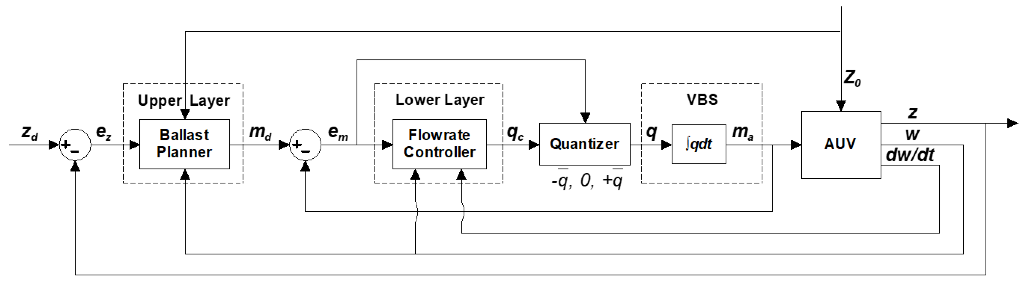
Based on the above studies, this work is devoted to the depth control system design for AUVs which are required to have capabilities of both satisfactory hovering, and low-speed and long-range cruising. To achieve this goal, a combined control strategy, which adopts bow and stern fins along with an on-off type VBS, is presented in this paper. The VBS is used for satisfactory hovering or fast descending/ascending without propulsion to reach the designated cruising depth, whereas the more energy-efficient fins act as the actuator to counteract the remaining small vertical unbalanced force due to the on-off type VBS and maintain the cruising depth. As in [
18], the on-off type VBS uses a single speed motor and a fixed displacement pump to generate a constant pump rate, while the electric valves are replaced by four fast-response direct-acting solenoid ones to improve the response performance of water flow direction control. A novel hierarchical architecture-based controller, which consists of a PD-type ballast mass planner and a flowrate controller, is proposed for the on-off type VBS to enhance the hovering performance. As for the fin control, the model-free PD controller which ensures the global asymptotic stability is applied.
The rest of this paper is organized as follows. The depth control problem of an AUV via VBS and fins is formulated in
Section 2. The combined depth control strategy is depicted in detail in
Section 3. The hierarchical on-off type VBS and the fin controllers design are presented in
Section 4. Verifications of the proposed approach, including simulations and basin tests, are conducted in
Section 5. Finally, the paper is concluded in
Section 6.
2. Problem Formulation of Depth Control via VBS and Fins
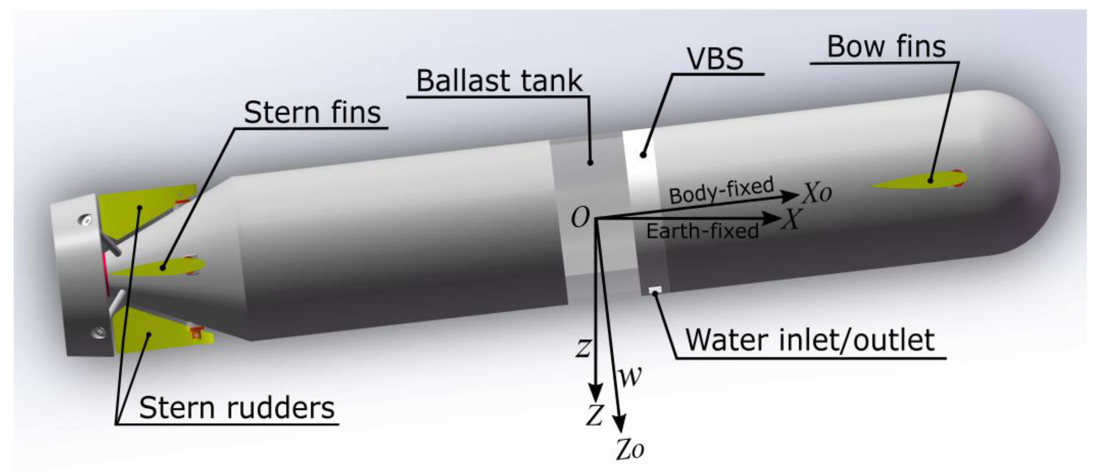
A typical configuration of an AUV equipped with VBS, and bow and stern fins is given in
Figure 1. The schematic diagram of the on-off type VBS, which uses a single speed motor, a fixed displacement pump and four fast-response direct-acting solenoid valves, is shown in
Figure 2 [
13].
Suppose the AUV is designed to have passive stability in both roll and pitch directions, and the ballast tank is configured to have the center at the origin of the body-fixed coordinate system. When operating at a depth below the wave-affected zone, underwater vehicles are commonly modeled with constant hydrodynamic coefficients [
36] and without sea wave disturbances [
37]. Under these assumptions, the heave dynamics of the AUV can then be simplified as [
36]
where
is the depth of the AUV,
is the heave velocity,
is the vehicle mass with empty ballast tank(s),
is the actual ballast mass,
,
and
are the constant hydrodynamic mass and the linear and quadratic damping coefficients, respectively,
is the gravitational acceleration,
and
are the lift coefficients of the bow and stern fins, respectively,
and
are the corresponding deflection angles of the bow and stern fins, respectively,
is the vertical imbalanced force,
is the on-off type mass flowrate,
is the overall mass of water contained in fully-filled ballast tank(s), and
is the constant flowrate of the on-off type VBS.
is caused by the unbalanced gravity (when the ballast tank(s) is/are empty) and buoyancy of the vehicle, and assumed to be known in prior. Note that the vehicle should be designed satisfying to enable free ascending without ballast, and to enable diving under the surface.
Denote the desired depth as
, and define the depth tracking error as
. Then, system (1) can be expressed as
For practical hovering or cruising, the VBS or the fin controllers to be designed work accordingly, such that , where is the required control accuracy.
3. Combined Depth Control Strategy
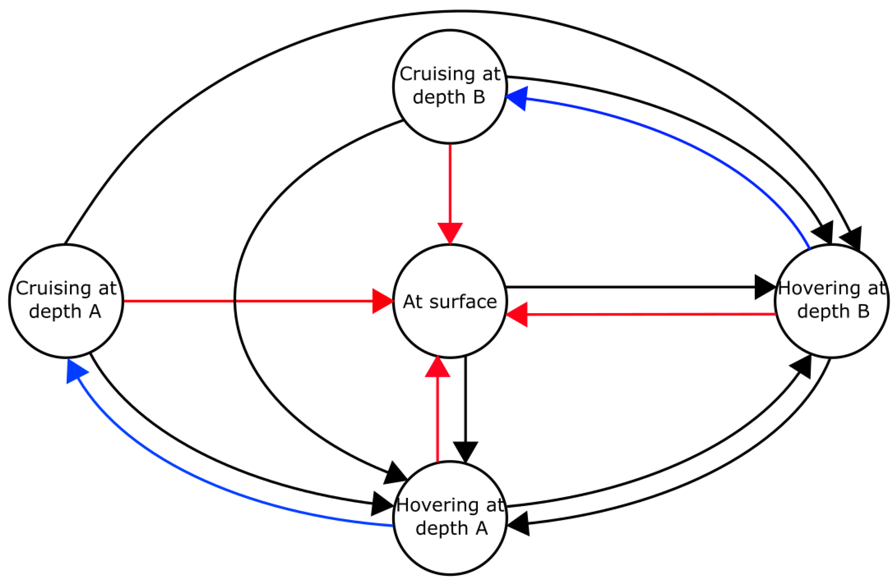
The combined depth control strategy is depicted in detail in
Figure 3. The states of an AUV in the depth control process are denoted by circles, and each directed line/arc connecting two states represents a state transition via VBS or fins. The color of a line/arc is used to differentiate different control actions: (1) black—close-loop control via VBS without propulsion; (2) blue—close-loop control via fins with propulsion; (3) red—open-loop control via VBS without propulsion. When there is more than one way for the transition of two states, the way with the minimum number of control steps (each line/arc is a control step) is adopted.
It should be noted that in practical applications, hovering via VBS is achieved once the vehicle reaches a quasi-static vertical equilibrium without forward velocity, i.e., the vehicle is allowed to trim within a small range from neutral buoyancy in seawater [
38]. In fact, due to the on-off type flowrate regulating mechanism, the vertical imbalanced force cannot be fully compensated by the VBS which will continuously work to counteract the left unbalanced effect, and this produces a small steady-state oscillation of hovering control of the vehicle, i.e., a limit cycle [
18]. Despite this, satisfactory hovering performance is achieved as long as it meets the practical requirements of control accuracy.
Due to this fact, for the transition from hovering to cruising at the same depth, a trigger condition should be determined based on the following principles: (1) the left vertical unbalanced force must be in the scope of the fins authority so that it can be counteracted by the fins; (2) the absolute value of depth error should be less than a preset criteria for fast maintaining the cruising depth via fins.
The proposed state transition in
Figure 3 from cruising at depth A to B, or vice versa, applies to when there is a large depth change, which takes long time, thus too much propulsion power consumption, for settling via the fins. For a small depth change, the transition can be done directly and quickly by fin control.
The advantages of the combined control strategy are that (1) vehicles can perform convenient diving/surfacing without propulsion via the energy-efficient, easily constructed and controlled on-off type VBS; (2) satisfactory and low-power hovering control can be achieved via the VBS, which effectively overcomes the absence or insufficiency of lift of the fins at zero or low speed; (3) the VBS can fulfill fast descending/ascending when there is a large change in the cruising depth, which will greatly shorten the transient period and thus reduce the propeller energy consumption; (4) the fins alone are actuated to counteract the remaining small vertical unbalanced force and maintain the desired depth, making cruising more energy-efficient.
5. Validation Results and Discussion
Simulation as well as basin test validations were conducted on a middle-sized AUV with a length and a maximal diameter of about 4 and 0.5 m, respectively, to assess the mass tracking and hovering performance of the developed on-off type VBS control system, and the depth control performance of the proposed combined control strategy. The AUV was designed and constructed by the State Key Laboratory of Ocean Engineering, Shanghai Jiao Tong University. Simulations were conducted in the MATLAB/Simulink environment, and experiments were carried out in the ocean engineering basin of the State Key Laboratory of Ocean Engineering, Shanghai Jiao Tong University.
The vehicle was equipped with a one-tank on-off type VBS. The physical parameters included , and . The CFD computed hydrodynamic coefficients were , and . The required depth control accuracy in this work is not worse than ±0.05 m, i.e., .
5.1. Simulation Validation
A comparative study on the mass tracking and the hovering performance of the proposed on-off and the continuous flowrate control is conducted.
Assume the vehicle has a net buoyancy of 1.35 kg when the ballast tank is empty, i.e.,
, and initially hovers at a certain depth, which means
or
, and is commanded to response to a depth change demand of 1 m. The controller parameters are determined as
,
and
. The thickness of the boundary layer of the mass tracking error is chosen as
. The simulation results are shown in
Figure 5,
Figure 6,
Figure 7,
Figure 8 and
Figure 9.
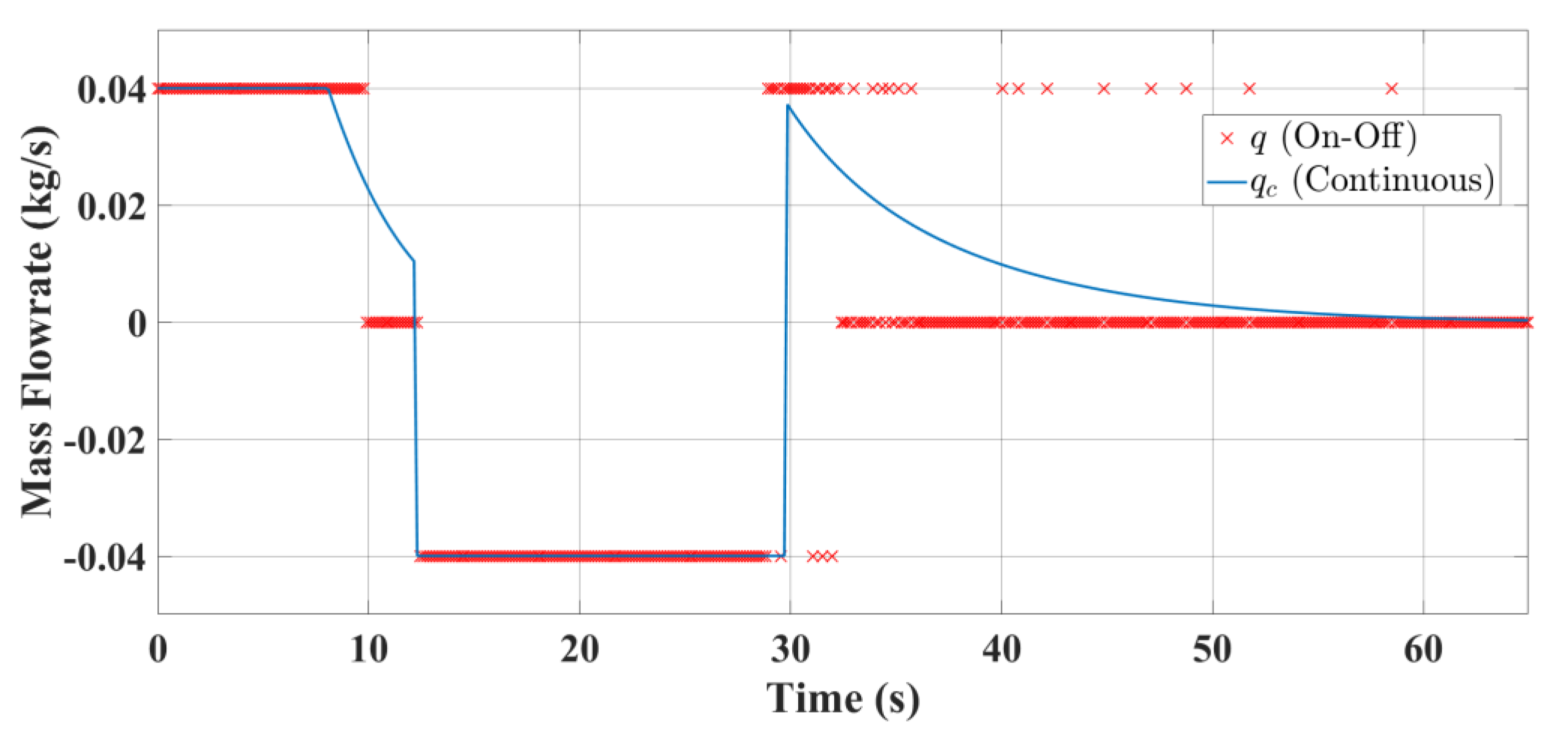
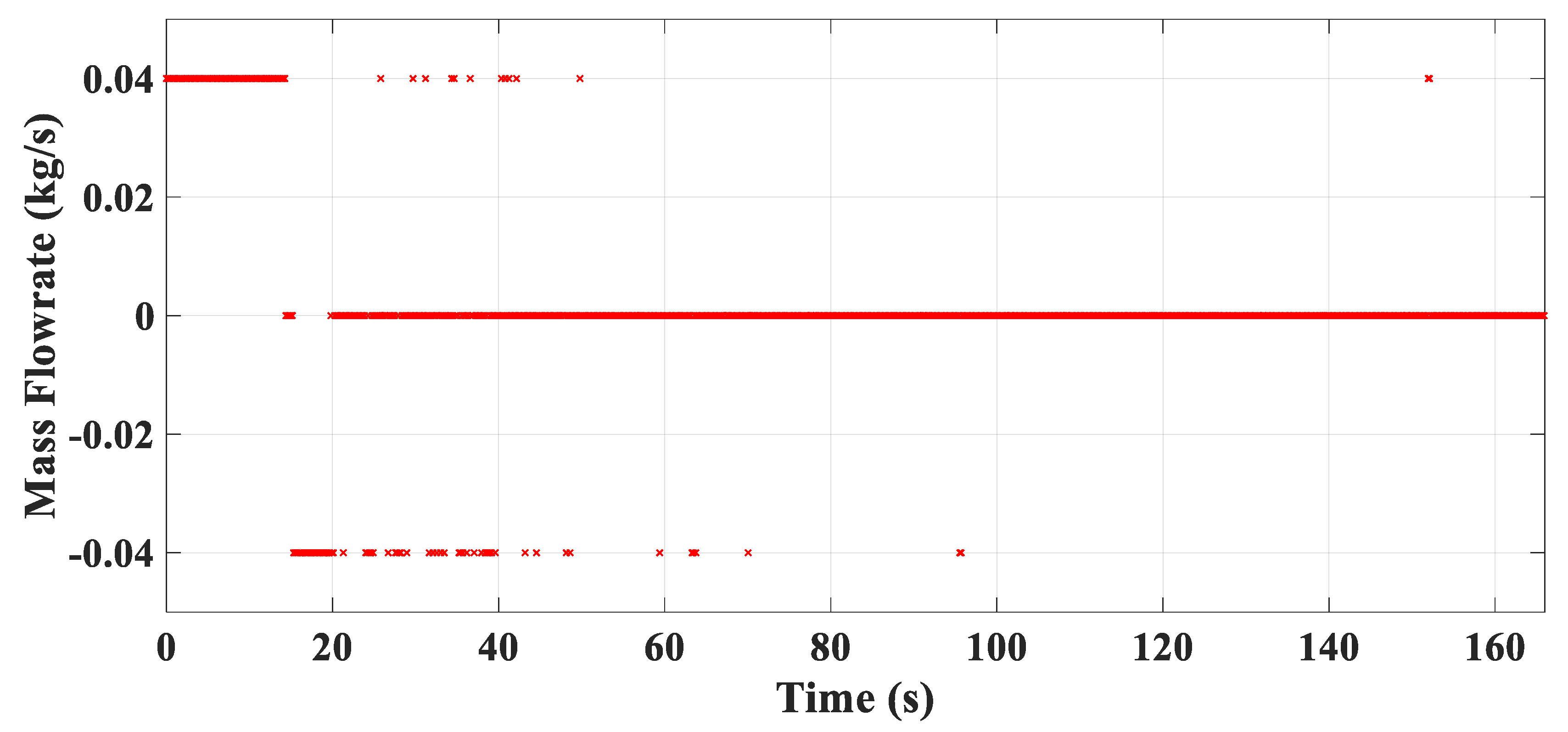
The mass flowrates of the on-off and the continuous VBS control are given in
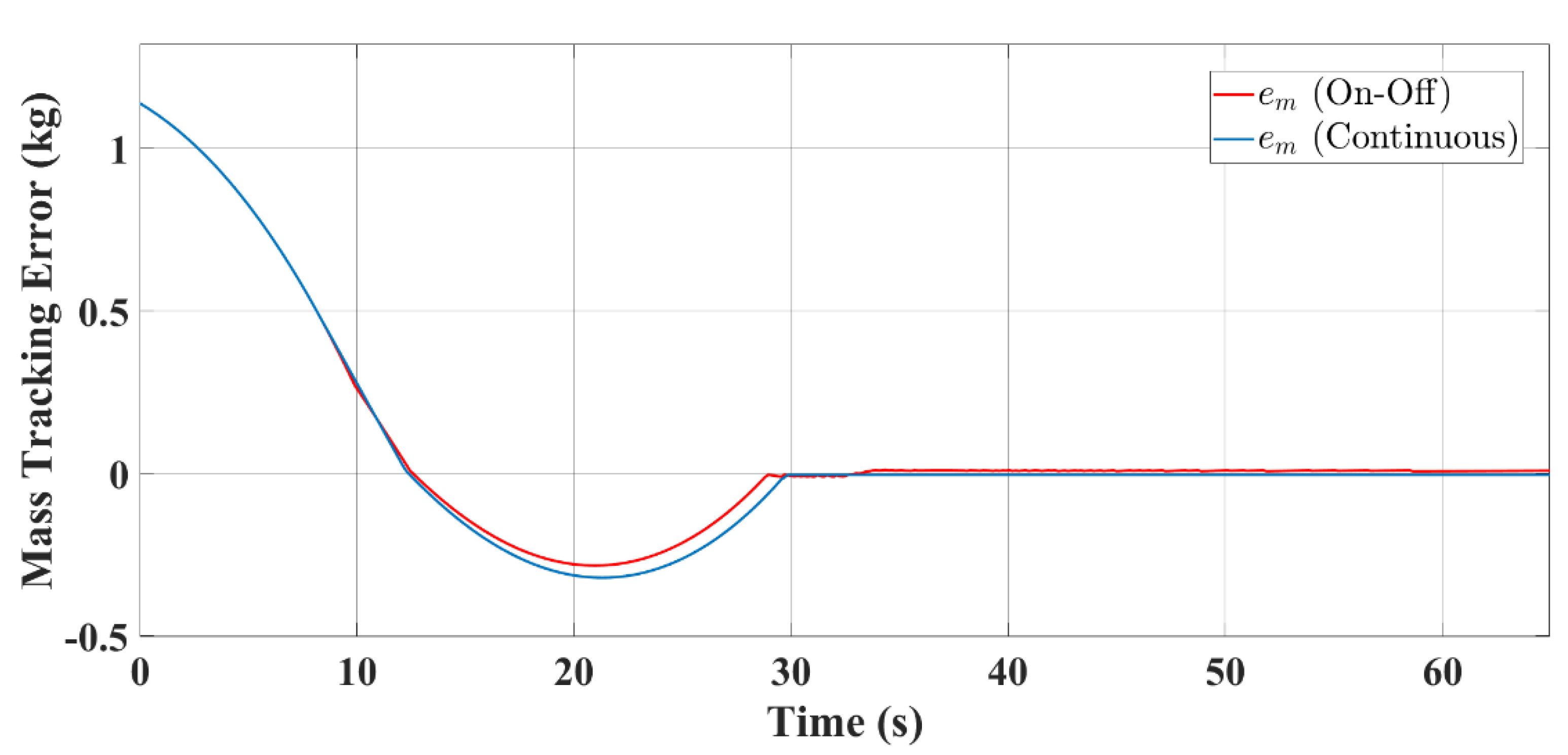
Figure 5. The detailed mass tracking performances can be observed in
Figure 6 and
Figure 7, which indicate that the actual masses of ballast water of both on-off and continuous type have a quick and satisfying tracking to their respective demanded values, and finally reach an agreement to counteract the imbalanced force
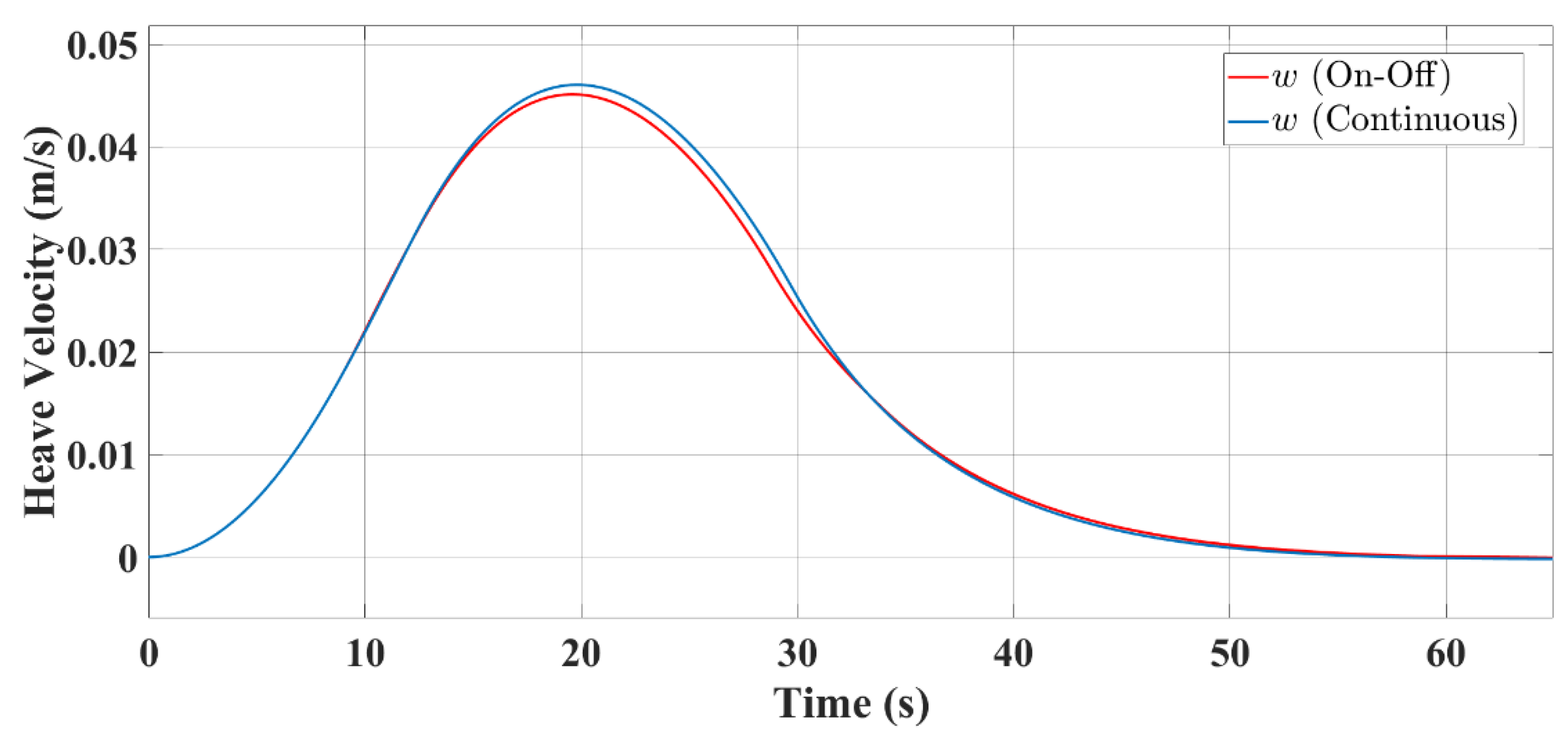
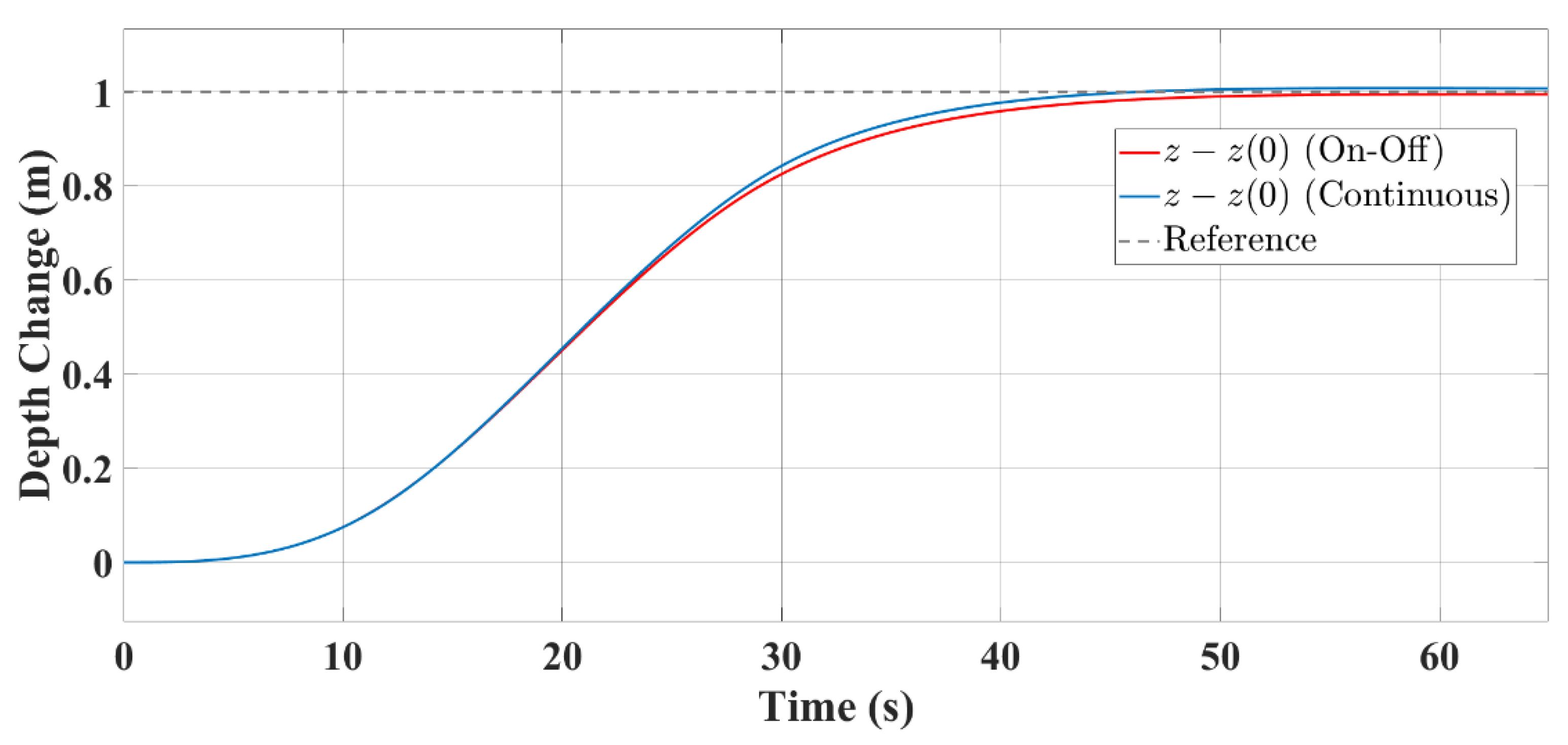
. The responses of heave motion states shown in
Figure 8 and
Figure 9 obviously demonstrate that the proposed on-off type flowrate control exhibits about equally desirable hovering performance as the continuous one. Both of the absolute depth errors are less than 0.01 m, assuring the required control accuracy.
It should be pointed out that negligible depth error can be observed in the on-off type control from
Figure 9. As explained in
Section 4.1.3, this is because accurate mass tracking cannot be achieved under the refined and quantized on-off flowrate law (15). Thus, the vehicle is finally in a quasi-static vertical equilibrium, and the VBS continuously works to counteract the small unbalanced force. This produces a negligible steady-state oscillation of the vehicle hovering, which can be seen if the simulation lasts long enough. Although the depth error could be reduced, to a certain extent, by choosing a smaller
to improve the precision of mass tracking, it is common to choose a larger
as long as it meets the practical requirements of control accuracy.
5.2. Basin Test Validation
Basin tests, which comprise two parts—hovering control via the on-off type VBS and depth control under the combined strategy—were carried out for further verification of the proposed on-off type VBS hovering control system and the combined depth control strategy.
5.2.1. Hovering Control via On-Off Type VBS
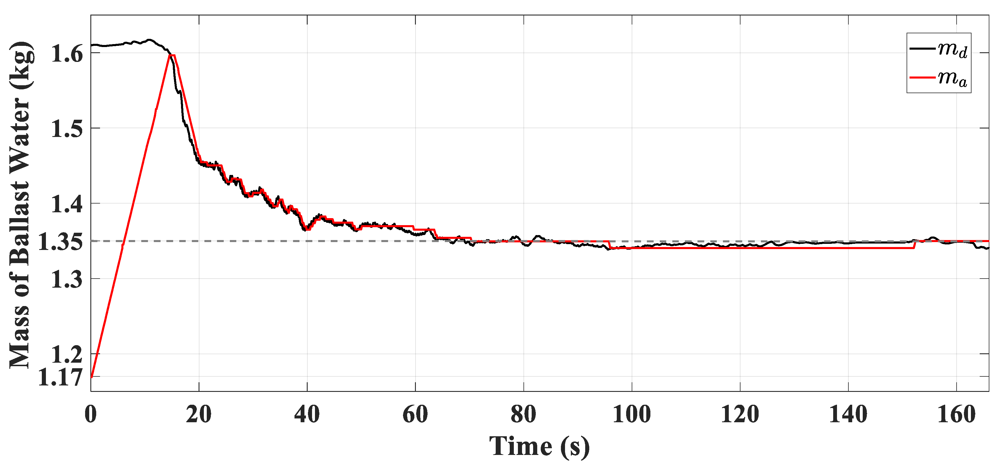
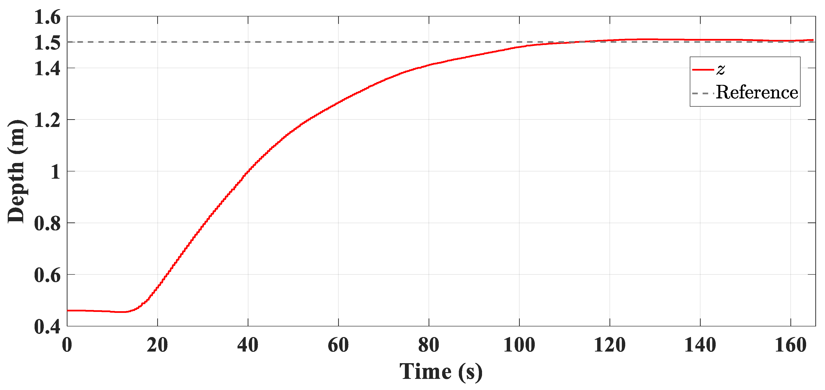
The vehicle has a net buoyancy of 1.35 kg with the ballast tank empty. It is required to dive from the water surface to the depth of 1.5 m with 1.17 kg of ballast water already in the tank. The parameters of the VBS controller are determined as , and . The thickness of the boundary layer of the mass tracking error is chosen as .
The experimental results are presented in
Figure 10,
Figure 11,
Figure 12 and
Figure 13, from which it can be seen that the dynamic mass tracking error is within ±0.01 kg and the absolute depth error is not worse than 0.01 m after settling. Both the mass tracking and the hovering control performance are well guaranteed under the proposed on-off flowrate control.
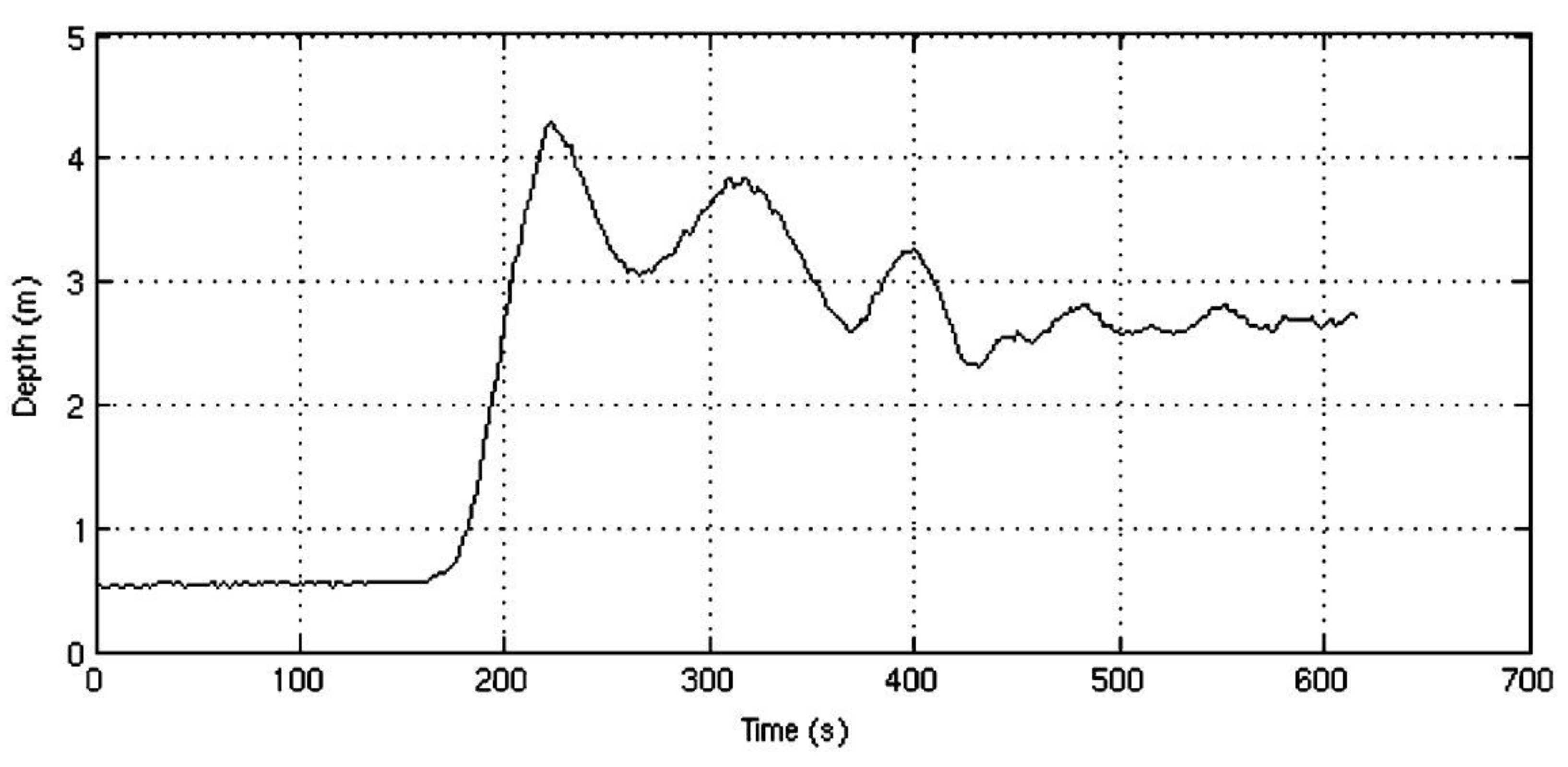
Figure 14 shows the hovering ability of the VBS depth controller of the Seahorse AUV in [
18]. It is plotted from an in-water test with a depth command of 2 m from the water surface. Although the vehicle finally hovers near the commanded depth, the hovering performance can be improved.
5.2.2. Depth Control under Combined Control Strategy
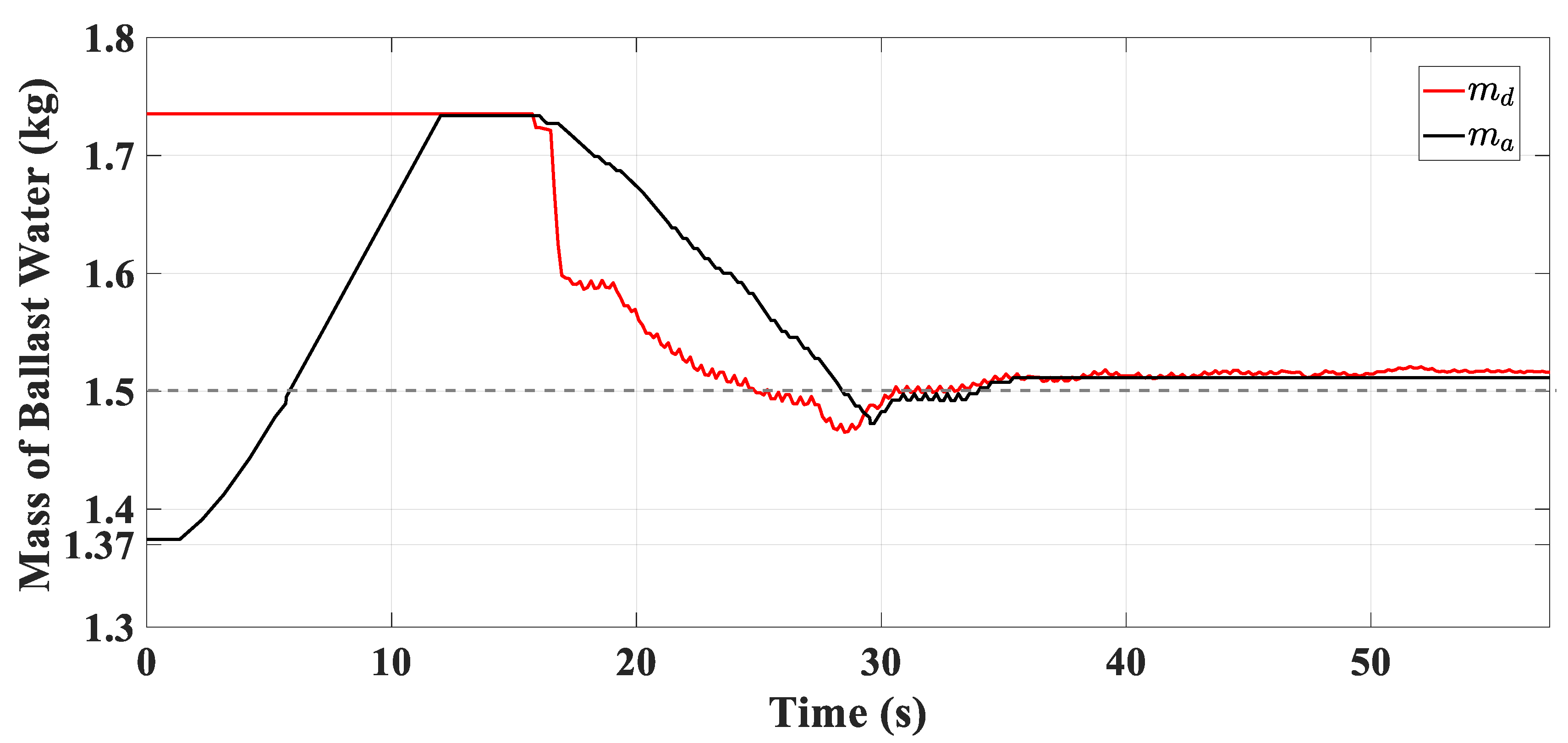
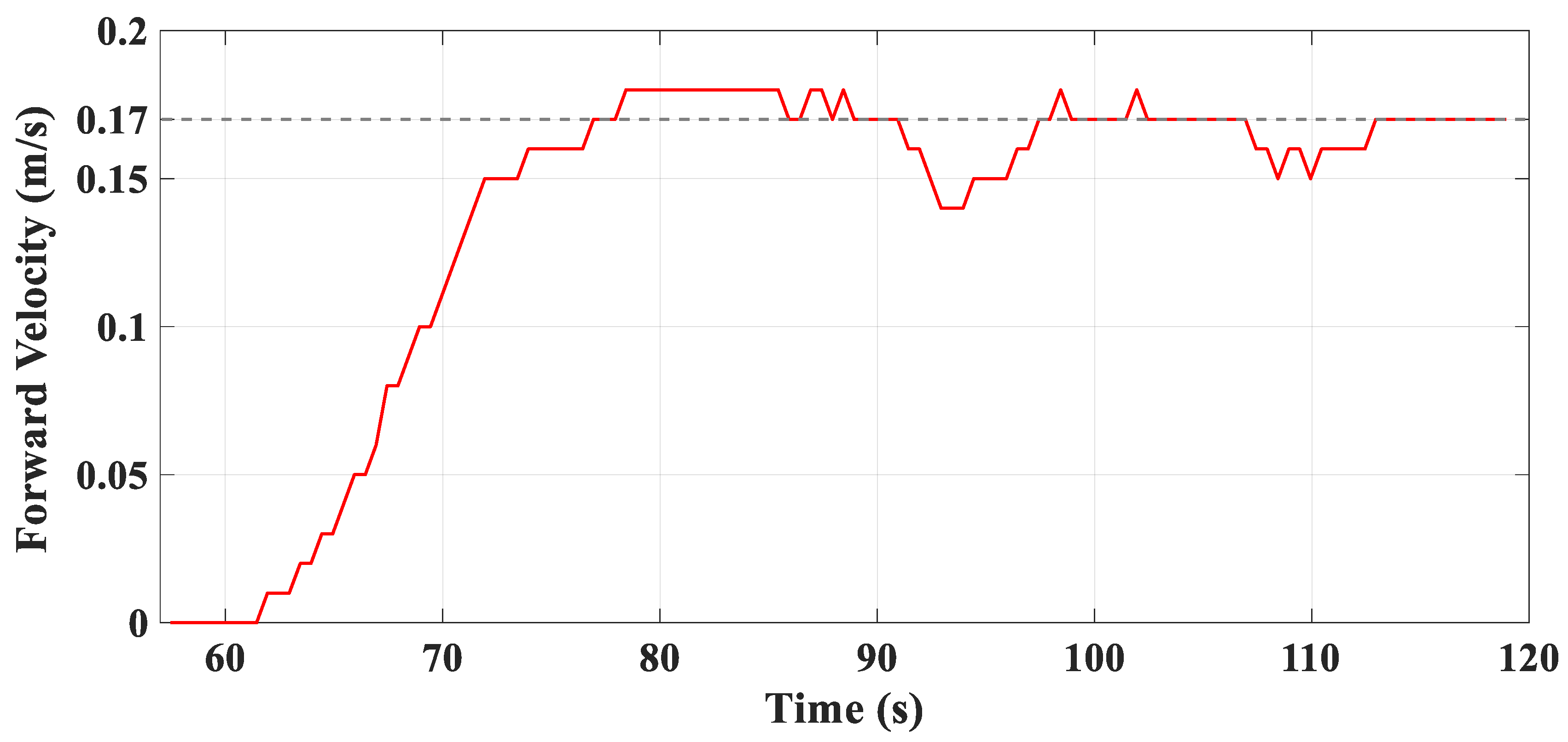
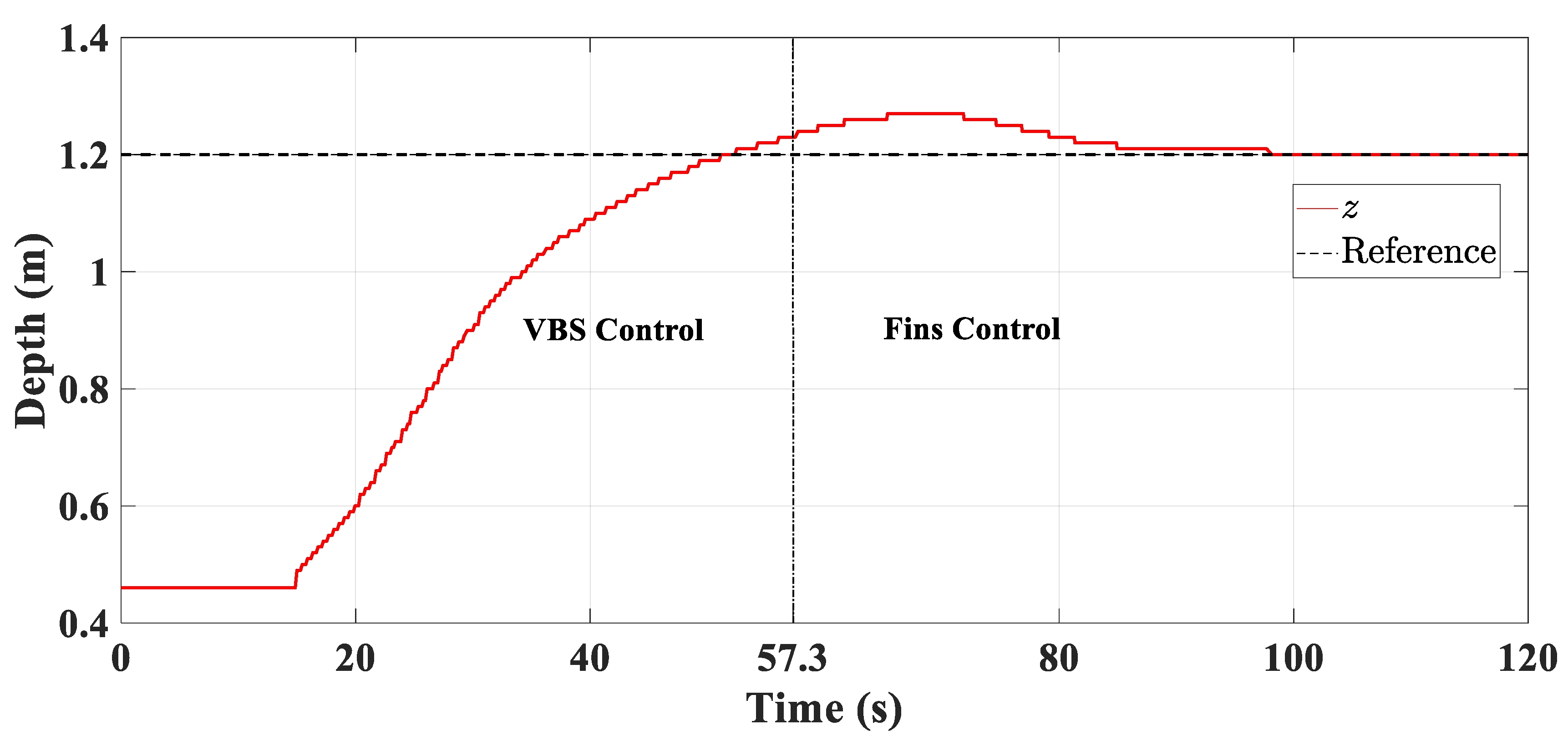
To validate the combined depth control strategy, the vehicle is commanded to launch from the surface and dive to the depth of 1.2 m via the on-off type VBS. Then, the VBS is stopped and the propelling system, as well as the fins and rudders, are triggered to work concurrently. The forward velocity is kept at a constant 0.17 m/s via the control of the propeller, and the heading angle is set as zero via the control of the stern rudders. The bow and stern fins work together at such operating conditions to counteract the small unbalanced force and maintain the cruising depth of 1.2 m.
The vehicle has a net buoyancy of 1.50 kg with an empty ballast tank. It is initially on the water surface with 1.37 kg of ballast water already in the tank. The lift coefficients of the bow and stern fins, at the constant forward velocity of 0.17 m/s, are
. And the fins are designed to have the same arm lengths, i.e.,
. Thus, the deflection commands of the bow and stern fins are always the same according to (20), and they are uniformly denoted by
.
is limited in the range of −20 to 20 deg as the fins have the best effect at
for the forward velocity of 0.17 m/s. The parameters of the fin controller are chosen as
and
. The experimental results are depicted in
Figure 15,
Figure 16,
Figure 17,
Figure 18,
Figure 19 and
Figure 20.
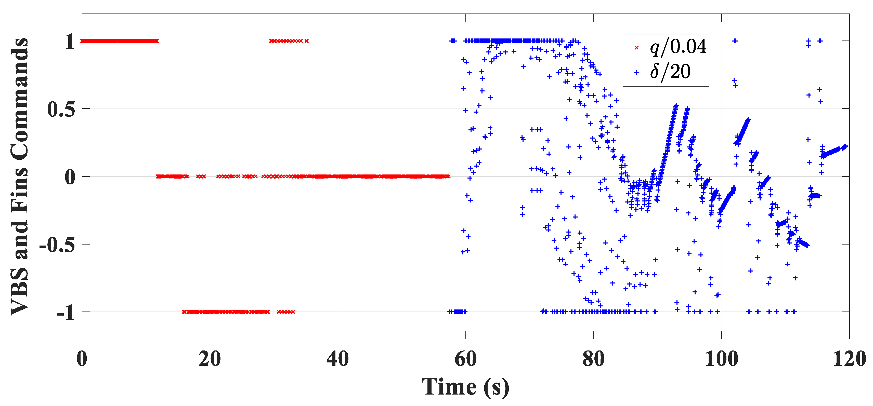
The normalized VBS and fin commands are given in
Figure 15 chronologically.
Figure 16 and
Figure 17 reveal the good mass tracking performance of the on-off type VBS again, despite the inherent small tracking error. The forward velocity response is depicted in
Figure 18, which shows that the vehicle reaches the velocity of 0.05 m/s, at which the fins come into play, at about
. The pitch angle response seen in
Figure 19 shows the good passive pitch stability of the vehicle. The satisfactory depth control performance of the combined control strategy is verified in
Figure 20. It shows that the VBS stops and the fins start working at
and the vehicle continues descending, due to inertia, to the maximum depth of 1.27 m at about
. It is at this moment that the fins take effect, and the depth is restored and well maintained with almost no steady-state error.
5.3. Hovering Control Performance under Model Uncertainty and Unknown Disturbances
The above work assumes that AUVs operate under nominal conditions, i.e., without modeling errors and external disturbances. As the precise estimation of the hydrodynamic coefficients is difficult, and unknown disturbance cannot be neglected when working under rough sea conditions, the behaviors of the proposed hovering control system with respect to such nuisances are further studied via simulations. The vehicle is assumed to have a net buoyancy of 1.35 kg when the ballast tank is empty and initially hovers at a certain depth, and is commanded to respond to a depth change demand of 1 m.
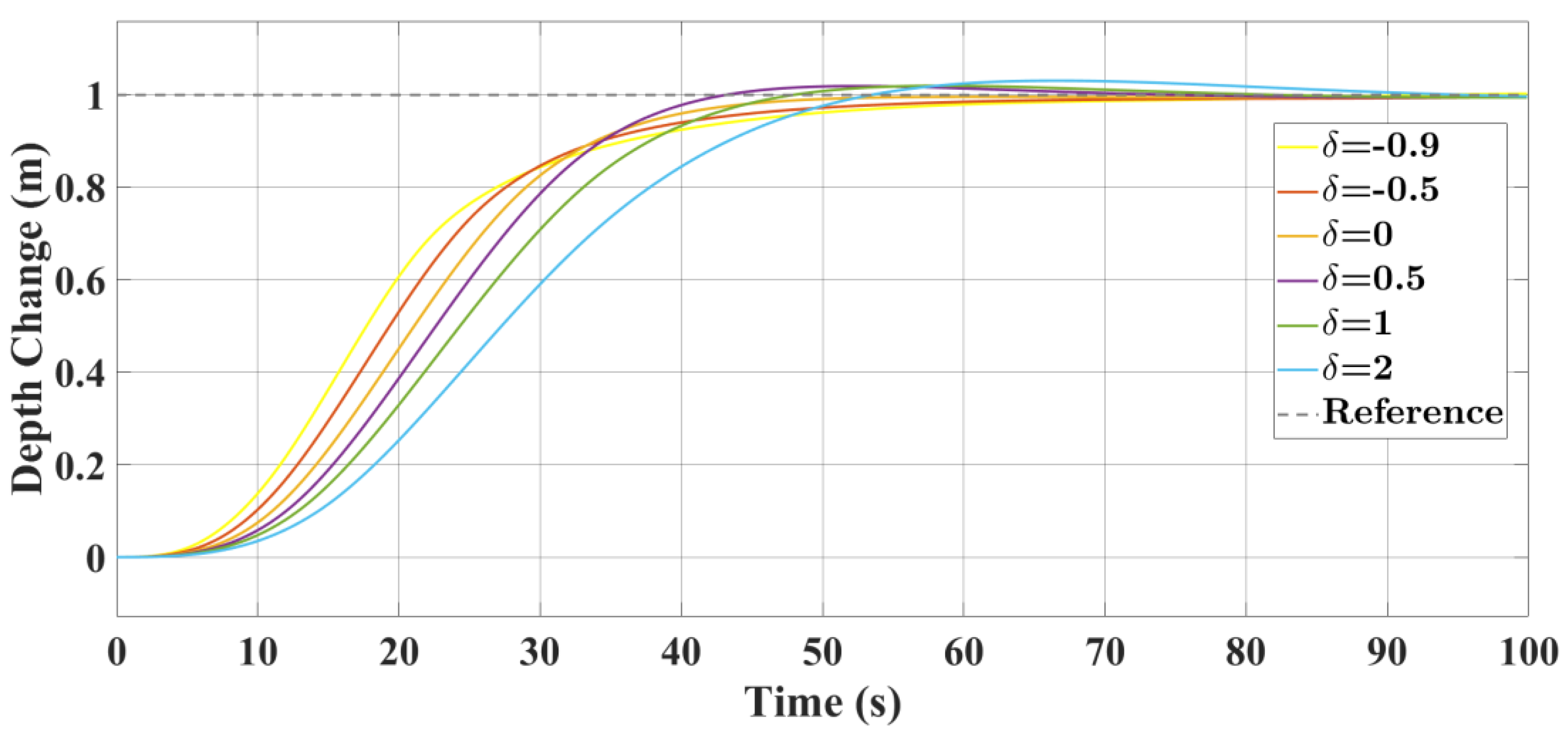
5.3.1. Hovering Control under Modeling Errors
Study of the proposed scheme for systems with different levels of modeling errors is done with the results presented in
Figure 21.
,
and
are used in the simulations instead of their nominal counterparts, where
is applied to describe the degree of modeling errors.
As is shown in
Figure 21, the robustness of the proposed method to system modeling errors is still guaranteed, despite the degradation of hovering performance with bigger overshoot (as
is positive and increases) or longer settling time (as
is negative and decreases).
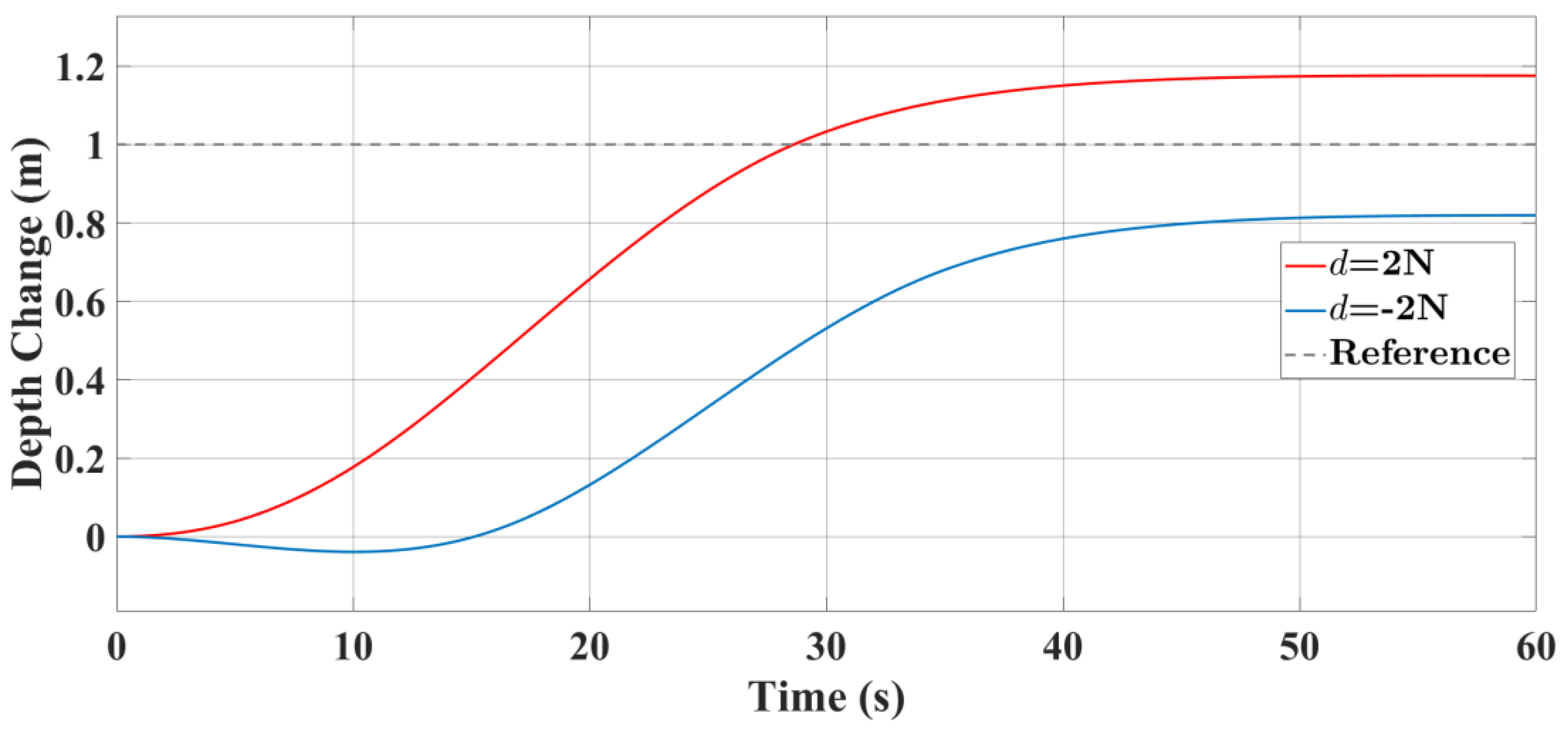
5.3.2. Hovering Control under External Disturbance
In this case, constant external disturbances of
and
are considered. The results in
Figure 22 show that steady state errors occur due to the unknown disturbances. For practical underwater missions, seawave or current disturbances which may be time-varying cannot be neglected. Thus, it is our future work to combine anti-disturbance strategies with the proposed hovering control scheme.


