Article

Ship Loading Influence on the Slamming Impact of Typical Sections of an S-175 Container Ship

1
School of Naval Architecture and Ocean Engineering, Harbin Institute of Technology, Weihai 264209, China
2
Shandong Institute of Shipbuilding Technology, Weihai 264209, China
*
Author to whom correspondence should be addressed.
J. Mar. Sci. Eng. 2020, 8(3), 163; https://doi.org/10.3390/jmse8030163
Submission received: 21 December 2019 / Revised: 15 February 2020 / Accepted: 27 February 2020 / Published: 3 March 2020
(This article belongs to the Special Issue Ship Hydrodynamics)

Abstract

:
This paper investigates the influence of ship-loading condition on slamming during water entry. Three typical sections of the S-175 container ship, namely the bow, parallel middle body and stern, under three different loading conditions are studied. Full-sized models are established and simulated by commercial software LS-DYNA based on the explicit finite element method (FEM) using the arbitrary Lagrangian–Eulerian (ALE) algorithm. At first, validation is carried out by simulating the Wave Induced Loads on Ships Joint Industry Project II (WILS JIP-II) ship section entering the water and by verifying that the response is in good agreement with published experimental data. Then, nine different cases with three typical sections of the container ship and three different loadings, including the no-load (lightship weight), half-load and full-load weights of the ship, are investigated. Finally, the influence of the ship loading and sectional shape on the water impacts is analyzed and discussed. The present study is useful for the analysis of loading effects on ship slamming at the early stage of ship design.

1. Instruction

Slamming consists of a powerful water impact between ship hulls and waves. The hydrodynamic force caused by slamming may lead to springing of the ship [1]. For container ships, the ongoing drive to increase container carrying capacity has resulted in rapid increase of ship size, which makes them susceptible to whipping and springing [2,3]. Prediction of slamming impact pressures is important in the structural design of all vessels, especially high-speed craft. The time interval of water entry is extremely short. Thus, large impulsive pressure loads may cause local deformation or failure of the ship structure. In rough sea, the slamming phenomenon cannot be avoided even at the stern or midship. For the S-175 container ship, its bow and stern suffer mainly from flare slamming, while for the midship, bottom slamming is a concern.
In the 1930s, Von Karman [4] and Wagner [5] developed theoretical formulas for the maximum pressures at the bottom of the float during landing, which agreed very well with the experimental results. Zhao et al. [6] developed two different theoretical methods for predicting slamming loads on two-dimensional sections, which were validated by comparison with experimental results from drop tests of ship cross sections. Tveitnes et al. [7] developed a test rig that drives a wedge section, with end plates, down guides to enter the water vertically at near constant velocity to measure the entry force. Wang et al. [8] experimentally and numerically investigated the water entry of a freefall wedge with a focus on the evolution of the pressure on the impact sides and the top side. A series of free-drop model tests were carried out by Wang [9], and the accelerations, slamming pressures and responses were measured. Based on the experimental results of Wang [9], an uncoupled method, combining Wagner theory and the finite element method, was presented to analyze the slamming problem for the 3D structure by Luo [10]. Mohammad et al. [11] addressed the water entry experiments of compliant slender bodies. Wang et al. [12] presented a new Computational Fluid Dynamics (CFD) method to simulate the physical process of a 2D elastic wedge entering water. Aquelet et al. [13] studied the water entry problem based on the Euler–Lagrange coupling algorithm. Yang et al. [14] studied the effect of an elastic structure subjected to water-entry slamming based on the double asymptotic approximation (DAA) method. Zhu et al. [15] studied the fully nonlinear free-surface deformations of initially calm water caused by the water entry and water exit of a horizontal circular cylinder, with both forced and free vertical motions using CIP (constrained interpolation profile) method. Watanabe et al. [16] conducted a model test in both regular and irregular waves to investigate the effects of bow flare on the deck wetness and asymmetry of the vertical wave bending moment. Wang et al. [17] carried out a freefall slamming experiment on a steel model of a hull section. The slamming pressure and structural elastic response stress on both sides of the steel model were measured. Hermundstad and Moan [18] used nonlinear strip theory to calculate the relative motions of ship and wave and found that water pileup around the bow due to the forward speed of the vessel significantly increases the slamming pressures. For the S-175 container ship, a series of model tests and numerical simulations have been carried out worldwide. Xu et al. [19] carried out a model test for an S-175 container ship model in regular waves and compared the experimental results with the results calculated by linear strip theory. Ramos et al. [20] conducted experiments for ship motions and sea loads on a segmented model of the S-175 container ship in ballast conditions and compared the vertical motions and bending moments between the measurements and the theoretical results. Fonseca et al. [21] conducted an experimental investigation of the nonlinear effects on the vertical motions and loads on the S-175 model advancing in irregular waves. Based on the explicit finite element software LS-DYNA, He et al. [22] simulated the water impact of three section models, and the water-entry velocity and the slamming pressures on the bottom were analyzed. A comprehensive review of research in loads on ship have been presented by Hirdaris et al [23]. As the further investigation of slamming, the study of hydroelasticity has been carried out in recent years. For example, Spyridon et al. [24] investigated the sensitivity to whipping and springing responses across a range of headings and sea states by two-dimensional hydroelasticity analysis. Recent advances and future trends of hydroelasticity has been presented by Hirdariset al. [25].
For transport vessels, the loading conditions often change due to different transportation tasks, so it is important to study the loading influence on the structural slamming. However, most studies on water slamming are focused on the material properties of the structure, water inflow rate, bottom angle, etc., and most work on S-175 container ships is focused on the effect of wave load on structure response. Few studies have been conducted on the loading influence on water slamming. Therefore, based on LS-DYNA, the loading influence on free-water slamming was studied. To analyze and reveal the loading influence on water slamming, systematic studies on the three S-175 container ship section models under different loading conditions were carried out. First, a two-dimensional WILS JIP-II hull section model was established. By analyzing and comparing the numerical simulation results and experimental data, the accuracy and reliability of LS-DYNA for simulating water slamming problems were verified. Then, according to the mass relationship between the lightship weight, half-load weight and full-load weight of a container ship [26], section models under different loading conditions were established. Finally, by calculating parameters such as speed and pressure during the water-entry process, the loading influence on water slamming was analyzed systematically.

2. Theory and Mathematical Models

2.1. Arbitrary Lagrangian–Eulerian Algorithm

An explicit finite element method with the ALE (Arbitrary Lagrangian–Eulerian) algorithm was used, which can avoid numerical diffusion and instability. The ALE algorithm is similar to the Euler algorithm; the difference is that the elements in ALE can motion freely. Lagrange time-step is employed, when deformation occurs to the elements due to the motion of the substance. So the ALE time step is executed: (1) To keep the topological relation, the boundary of the substance is kept with the inner elements re-meshed; (2) the element parameters (e.g. density, energy) and the node speed are transformed to the re-meshed elements. Figure 1 shows the difference between the Lagrange, Euler and ALE algorithms.
The governing equations can be given by the mass, momentum and energy conservation equations:
ρ t = ρ v i x i w i ρ x i
ν ν i t = σ i j , j + ρ b i ρ w i ν i x j    
ρ E t = σ i j ν i , j + ρ b i ν i ρ w j E x j  
where t indicates time; ρ indicates density; the relative velocity w is the difference between the material velocity v and the grid velocity u; xi,j represents the Euler coordinates; σ i j is the stress tensor; and E is energy.

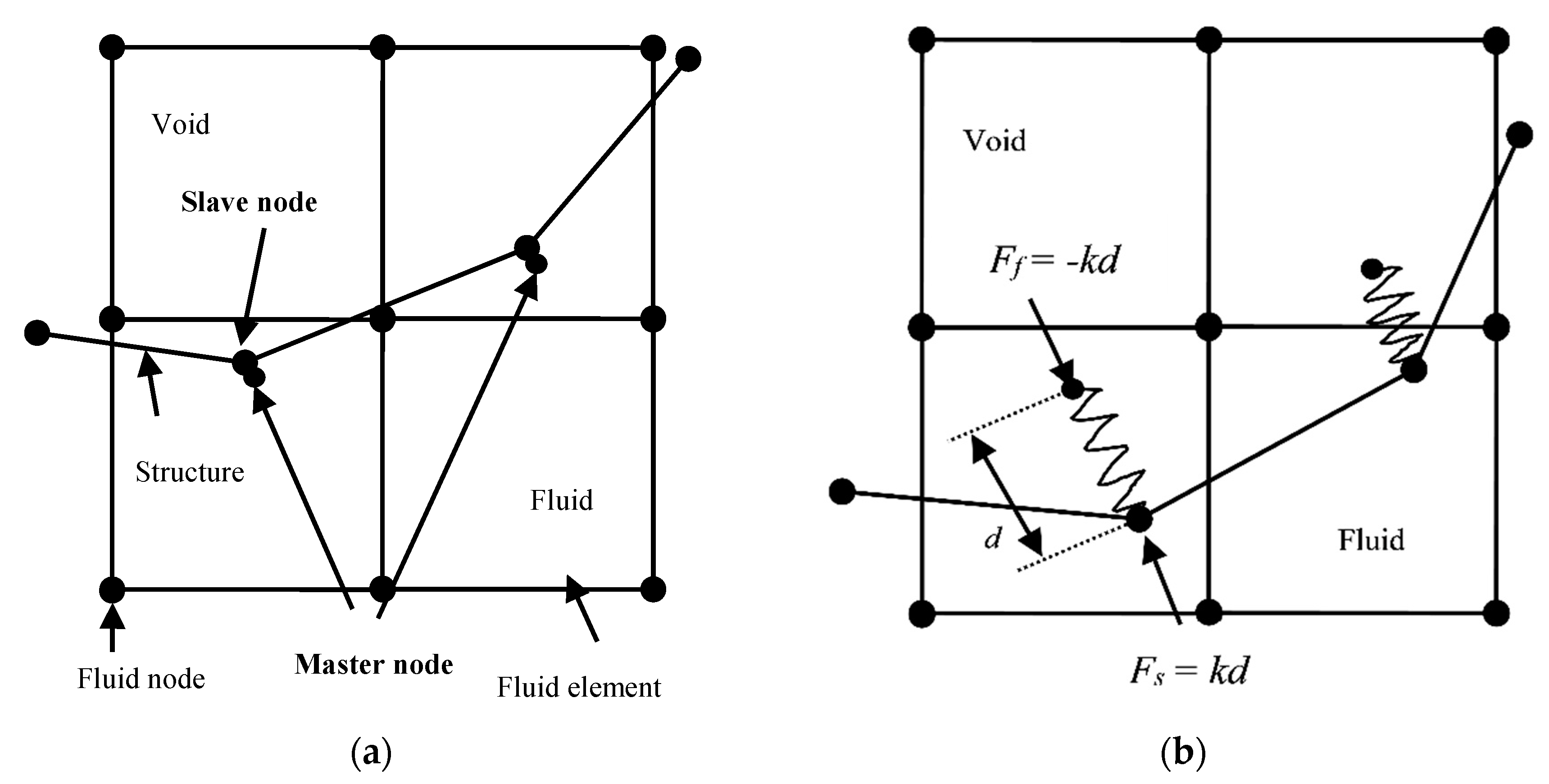
2.2. Penalty Function Coupling Method

The penalty function coupling method [13] is employed to deal with the fluid-structure-coupling problem in the present study. Figure 2 shows the law of the penalty function coupling method. This coupling method calculates the pressure at each point on the contact surface by the relative displacement d and the derivative of time. Then, the pressure is applied to the nodes on the contact surface, which blocks the fluid from penetrating the structure. The coupling force F is described as:
F = k × d
where k is the stiffness coefficient of the penalty function and d is the relative displacement between the slave substance and the master substance. Force F acts on the slave substance and the master substance at the same time in the opposite direction to ensure the balance of forces on the contact surface. Ff at the fluid nodes is the fluid force, while Fs is the force at the structure coupling node.
When the stiffness coefficient of the penalty function k tends to infinity, the relative displacement d tends to zero. Though the contact surface cannot be penetrated, it affects the overall stiffness of the system. The stiffness coefficient of the penalty function is given by the following equation:
k = P f K A 2 v  
where P f is the scaling factor of penalty function stiffness; K indicates the bulk modulus of the fluid; and V is the volume of the fluid unit containing the master material node. A is the average area of the structural elements associated with the slave nodes on the coupling surface. By choosing an appropriate value of P f , the mutual penetration between the master substance and the slave substance can effectively be controlled, while the overall stiffness of the system is not significantly affected.

2.3. Equation of State

A linear polynomial equation of state (EOS) is used for the internal energy. The pressure is given by:
P = C 0 + C 1 μ + C 2 μ 2 + C 3 μ 3 + ( C 4 + C 5 μ + C 6 μ 2 ) × E
where P is pressure; C0 to C6 indicate the polynomial equation coefficients; E is internal energy; μ is given by the following equation:
μ = α 0 α - 1 - 1
where α 0 and α indicate the initial specific volume and specific volume, respectively. The value of C0 to C6 is given based on Li et al. [27]. The EOS parameters of each material are shown in Table 1. E0 and V0 indicate the initial internal energy per unit reference volume and initial relative volume, respectively.

3. Validation Study

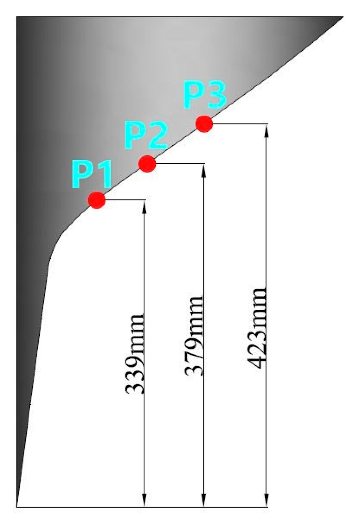
3.1. WILS JIP-II Hull Section Model

To validate the numerical model, the water slamming problem of the Wave Induced Loads on Ships Joint Industry Project II (WILS JIP-II) hull section model was simulated based on the model experiment [28]. The model is free to release at a distance of 0.3 m from the center of gravity to the free surface of the water. Test parameters and pressure gauges of the model are shown in Table 2 and Figure 3, respectively.
A half computational domain is employed in this validation. The minimum size of the mesh is 0.05 m. The grids for the WILS JIP-II hull section are shown in Figure 4.

3.2. Validation of the Numerical Model

The comparison of the pressure on the gauges between the present results and available experimental data is shown in Figure 5. The solid line is the numerical result, while the dot is the experimental data from Hong et al. [28]. From Figure 5, it can be seen that the numerical results generally agree well with the experimental data, while an overestimated peak of the pressure by the numerical model is also found, especially for P1 gauge. The reason of this overestimated pressure peak may be due to the three-dimensional effect in the experiment. Another reason can be considered as the numerical inaccuracy in capturing the peak of pressure, since the peak of the pressure is sensitive to the numerical schemes, numerical grids, time steps and so forth. Although the peak of the pressure is overestimated, the above comparison generally validates the present LS-DYNA numerical model.

4. Numerical Results and Discussion

4.1. Ship Model and Initial Condition Setting
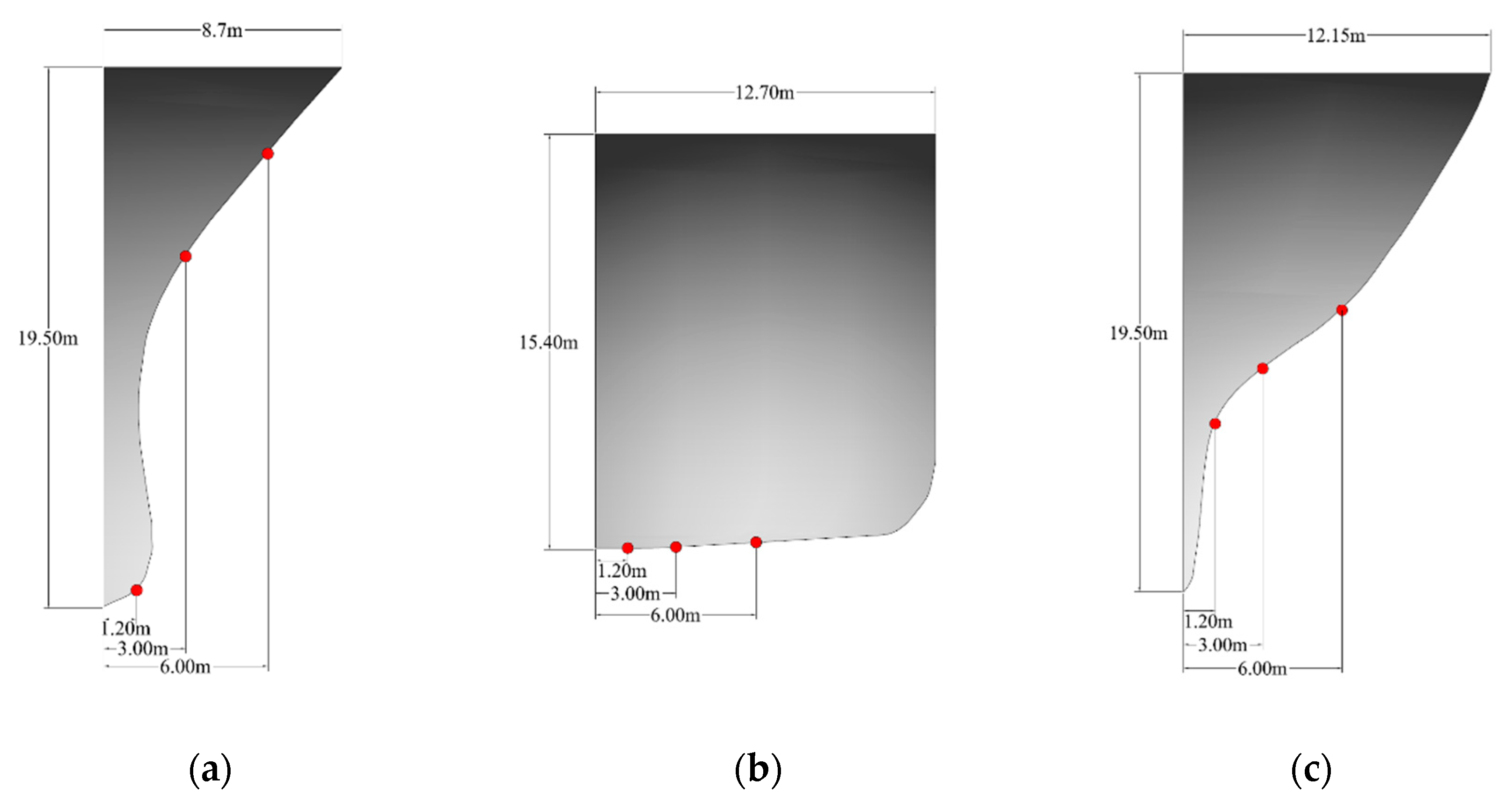
Three typical cross sections of an S-175 model, including bow, parallel middle body and stern, are selected, which correspond to station numbers 19, 10 and 1, respectively. The three sectional models are established and simulated in full-scale size. Table 3 and Table 4, respectively, list the main dimensions of the S-175 container ship and the water-entry velocity of each section. The velocity is given by He et al. [29]. The parameters of materials are shown in Table 5. The sectional models are set to be rigid parts to avoid the influence of elastic response. Figure 6 shows the body plan of S-175, and Figure 7 shows the cross section of S-175. The positions of the pressure gauges P1 (x = 1.2 m), P2 (x = 3 m) and P3 (x = 6 m) are shown in Figure 7.
Benefiting from the symmetry of the hull structure and the simulation problem, the present study uses a half computational domain. The left boundary of the calculation domain (x = 0) is set to a symmetric boundary. Other boundaries are set to nonreflective boundaries. The water depth, height above the water (air area) and half width of the computational domain are set to 30, 40 and 100 m, respectively. A nonuniform grid is used except for the grids near the water surface, which are evenly arranged. Thin shell elements are used for the ship structure, while the fluid domain is established by 1 point ALE multi-material elements [30]. The minimum size of the mesh is 0.05 m. The grids for the bow section are shown in Figure 8.
The loading in the ship can affect the response of ship motion, correspondingly affecting the heave velocity (water-entry velocity) and slamming pressure. The mass of the bow, parallel middle body and stern sections at no-load (lightship weight), half-load and full-load conditions are shown in Table 6.

4.2. Bow Section

Figure 9 shows the time history of the velocity of the bow section under different loading conditions. The change of the velocity of the section under the three loading conditions shows a similar trend [17]. Because the mass of the section is light under no-load (lightship weight) conditions, the gravity of the bow is quickly balanced with the fluid force it receives from the water. It can be confirmed from Figure 9 that the turning point of the velocity of the section under the no-load (lightship weight) condition is earlier than for the half-load and full-load conditions. The time instant of the turning point in the velocity curve under full-load conditions is obviously earlier than for the no-load (lightship weight) condition. This is because the wave splashes from the bottom of the bow reaches the side of the bow and creates a slamming phenomenon. Figure 10 shows the scenarios of the flare slamming under no-load (lightship weight) and full-load conditions for a 14.6 m falling height of the bow. As shown in Figure 10, the larger the loading is, the more intense the splashing waves are, which means a greater slamming force is induced.
The slamming of the bow is mainly divided into two phenomena: flare slamming and slamming when entering the water. Therefore, the pressure gauge P1 is set at the head of the bow, and P2 and P3 are set at the side surface of the bow. The slamming forces of the bow section under the three loading conditions are shown in Figure 11, and Figure 12, Figure 13 and Figure 14 show the pressure at the three gauges under no-load (lightship weight), half-load and full-load conditions, respectively.
As shown in Figure 11, three stages in the slamming force of the bow are clearly observed even under different loading conditions. In the first stage, the bow begins to fall into the water, and the bow section is subjected to a small slamming pressure. In the second stage, flare slamming occurs at the side of the bow, which causes a large slamming pressure. In the third stage, the cavity between the hull and fluid disappears, and the backward flow around the hull side causes another high peak impact. From Figure 11, it can be seen that the slamming force of the bow section increases as the loading increases. In particular, the flare slamming force at the second stage mentioned above increased greatly, which confirms the idea that a larger loading induces a greater flare slamming force on the bow section.
It can be seen from Figure 12, Figure 13, and Figure 14 that two large pressure peaks occur at P2. One peak occurs at the moment when the flare slamming occurs, and the other peak occurs at the moment when the cavity disappears. The increase in the loading leads to a sharp increase in the first peak; the influence on the second peak is smaller. In other words, the loading has a strong influence on the flare slamming of the bow.

4.3. Parallel Middle-Body Section

Figure 15 shows the velocity of the parallel middle body under different loading conditions. No flare slamming occurs in this case. The first turning point of the velocity of the parallel middle body occurs in the order of the no-load (lightship weight), half-load and full-load conditions. The second turning point of the velocity occurs at the moment when the bottom is in full contact with the free water surface. After that, the velocity of the parallel middle body changes smoothly, showing a trend of first increasing and then decreasing. As the loading increases, the velocity of the body increases significantly.
The section shape of the parallel middle body is similar to a rectangle shape, which suffers mainly from bottom slamming. The slamming forces of the parallel middle body section under the three loading conditions are shown in Figure 16. Figure 17, Figure 18 and Figure 19 show the pressure at each gauge under no-load (lightship weight), half-load and full-load conditions, respectively.
It can be seen from Figure 16 that the slamming force of the parallel middle body occurs mainly at the moment when it touches the water, and the influence of the loading on the slamming force is small. However, after the process of water entry becomes stable, the force on the parallel middle body gradually increases, and the larger the loading is, the greater the increase is. According to Wagner’s theory, the slamming pressure at any position of a wedge can be expressed by:
Pi = ρ Kw Vn2
where ρ indicates the density of the coupled fluid; Kw is the dimensionless pressure coefficient, which is determined by the deadrise angle of the wedge; and Vn is the impact velocity of the wedge. At the stage where the water entry becomes stable, we can see from Figure 15 that, as the loading increases, the velocity of the parallel middle body becomes significantly larger, so the phenomenon mentioned above occurs.
By comparing the pressures at each gauge in Figure 17, Figure 18 and Figure 19, it can be found that the increase in loading has little influence on P1 and P2, which are placed near the centerline of ship section, while the pressure at P3, near the side of the ship, is strongly affected. This is because the change in loading has little influence on the velocity of the section at the initial stage during water entry. According to Equation (6), the slamming pressures at P1 and P2 at the moment of contact with water are not sensitive to the different loading conditions. However, when the P3 gauge contacts the water, the difference in velocity of the section among the three loading conditions is larger. Therefore, the pressure under the full load condition is much greater than that under the no-load (lightship weight) condition.

4.4. Stern Section

The shape of the stern section is similar to that of the bow section. However, since the body-plan of the stern section is smoother than that of the bow, the water-entry process of the stern is much gentler than that of the bow. Figure 20 shows a snapshot of water entry of the stern at t = 1.4 s under full loading. Although the stern suffers mainly flare slamming, there is no flare slamming phenomenon under the full load conditions.
As shown in Figure 21, no significant change occurs in the velocity of the body at the moment when the bottom of the stern starts to enter the water. Because there is no flare slamming, the order of velocity turning points is no load (lightship weight), half load and full load. Compared with the case of the parallel middle body, the difference in velocity of the stern under the three loading conditions is smaller after the water-entry process is stable.
It can be seen from Figure 22 that since there is no flare slamming, the influence of the loading on the stern’s slamming force is relatively small. Similar to the case of the parallel middle body, when the process of water entry becomes stable, the pressure on the stern gradually increases, and the larger the loading is, the greater the increase is.
Comparing the pressures at each gauge in Figure 23, Figure 24 and Figure 25, it can be seen that the peak value at each point increases significantly with increasing loading; as the loading becomes larger, the pressure after the peak is also larger. This is consistent with the trend of the slamming force.

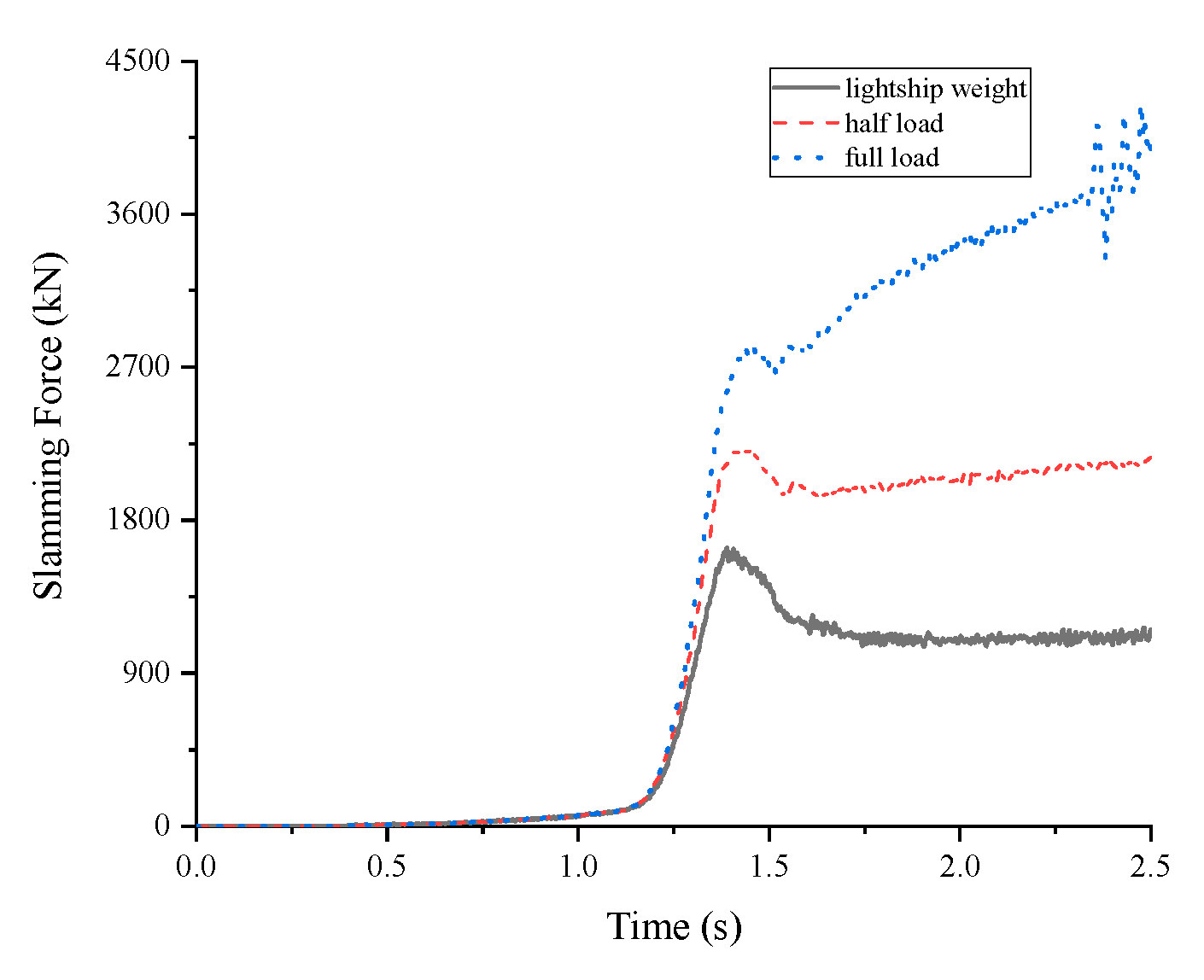
4.5. Loading Sensitivity Analysis

The sectional shape has a great influence on the velocity, force and pressure of the sections. The sensitivity of different sections to loading conditions is also different. In this section, the data of the three sections under the three loading conditions are compared and analyzed to investigate the loading sensitivity on the water entry of different sections.
Figure 26 shows the velocity of each section under each loading condition. It can be seen from Figure 26a that the velocity during water entry of the parallel middle body changes less than for the cases of the bow and the stern. By comparing Figure 26a–c, it can be found that as the loading increases, the peak value of the velocity of each section increases, and the velocity of the parallel middle body is most sensitive to the loading.
Figure 27 shows the slamming forces of different sections under each loading condition and the peak value and their growth rates are shown in Table 7. By comparing Figure 27a–c and Table 7, it can be found that the peak of the slamming force of the parallel middle body is not very sensitive to the loading, and the first peak of the bow is more affected by the loading due to the flare slamming. After the process of water entry becomes stable, the slamming forces of the three sections increase with increasing loading. The parallel middle body is most affected by the loading.
Figure 28 shows the variation of the slamming pressure at P2 under different loading conditions, and the peak value and their growth rates are shown in Table 8. Under each loading condition, the peak pressure of the parallel middle body is much larger than that of the bow and the stern, but the loading has little influence on the peak value. The peak of the slamming pressure of the bow is greatly influenced by the loading. The difference in the pressure peak between the no-load (lightship weight) and full-load conditions is nearly a factor of two. Therefore, in the process of water entry, the slamming force of the bow is most influenced by the loading due to flare slamming; because of the large difference in the velocity under different loading conditions, the slamming force of the parallel middle body is influenced by the loading more than that of the other two sections when the water entry becomes stable.

5. Conclusions

The influence of the loading and shape of sections on the slamming pressure was studied based on LS-DYNA. The process of the water entry of three typical sections, including the bow, parallel middle body and stern, under three loading conditions (no load (lightship weight), half load and full load) was simulated and discussed. By analyzing the velocity, force and pressure of the S-175 container ship sections under each loading condition, it can be concluded that: (1) For the bow section, the first peak of slamming force induced by the flare slamming is greatly influenced by the loading condition. (2) For the parallel middle body, its slamming force is much larger than that of the bow and the stern section, but the peak is less sensitive to the loading. However, the loading has a greater influence on the slamming force after the water entry becomes stable. (3) For the stern section, it has a smaller slamming force than that of the bow and the parallel middle body sections, and the force and pressure change smoothly in the water-entry process. According to the above investigation, the ship slamming force is sensitive to the loading and the section shape, so both of them need to be considered carefully in the early stage of ship design.

Author Contributions

Conceptualization, G.H.; data curation, P.J.; formal analysis, S.L.; funding acquisition, G.H.; investigation, B.X. and W.W.; methodology, G.H.; project administration, G.H.; resources, G.H.; software, B.X. and S.L.; supervision, G.H.; validation, B.X., W.W. and P.J.; writing—original draft, B.X.; writing—review and editing, G.H. All authors have read and agreed to the published version of the manuscript.

Funding

This research was funded by the National Natural Science Foundation of China (51579058), Taishan Scholars Project of Shandong Province (tsqn201909172), Shandong Province Key R&D Program (2019GHY112024), and University Young Innovational Team Program, Shandong Province (2019KJN003), State Key Laboratory of Hydraulic Engineering Simulation and Safety, Tianjin University (HESS-1907).

Conflicts of Interest

The authors declare no conflict of interest.

References

  1. Wu, J. Study on the Hydroelastic Impact Test and Numerical Simulation of One Stiffened Wedge Body; Tianjin University: Tianjin, China, 2013. [Google Scholar]
  2. Southall, N.; Choi, S.; Lee, Y.; Hong, C.; Hirdaris, S.; White, N. Impact Analysis using CFD—A Comparative Study. In Proceedings of the Twenty-Fifth International Ocean and Polar Engineering Conference, Kona, HI, USA, 21–26 June 2015; pp. 692–698. [Google Scholar]
  3. Lee, Y.; Wang, Z.; White, N.; Hirdaris, S. Time domain analysis of springing and whipping responses acting on a large container ship. In Proceedings of the ASME 2011 30th International Conference on Ocean, Offshore and Arctic Engineering, Rotterdam, The Netherlands, 19–24 June 2011; pp. 1–9. [Google Scholar]
  4. Von Karman, T. The Impact on Seaplane Floats during Landing; National Advisory Committee on Aeronautics: Washington, DC, USA, 1929; pp. 1–8.
  5. Wagner, H. Phenomena associated with impacts and sliding on liquid surfaces. Z. Angew. Math. Mech. 1932, 4, 193–215. [Google Scholar] [CrossRef]
  6. Zhao, R.; Faltinsen, O.; Aarsnes, J. Water entry of arbitrary two-dimensional sections with and without flow separation. In Proceedings of the 21st Symposium on Naval Hydrodynamics, Trondheim, Norway, 24–28 June 1996; pp. 408–423. [Google Scholar]
  7. Tveitnes, T.; Fairlie-Clarke, A.C.; Varyani, K. An experimental investigation into the constant velocity water entry of wedge-shaped sections. Ocean Eng. 2008, 35, 1463–1478. [Google Scholar] [CrossRef] [Green Version]
  8. Wang, J.; Claudio, L.; Odd, M.F. Experimental and numerical investigation of a freefall wedge vertically entering the water surface. Appl. Ocean Res. 2015, 51, 181–203. [Google Scholar] [CrossRef] [Green Version]
  9. Wang, H. Research on Ship Slamming Loading and Local Structure Dynamic Response; China Ship Scientific Research Center: Wuxi, China, 2010. [Google Scholar]
  10. Luo, H.; Wang, H.; Soares, C.G. Numerical and experimental study of hydrodynamic impact and elastic response of one free-drop wedge with stiffened panels. Ocean Eng. 2012, 40, 1–14. [Google Scholar] [CrossRef]
  11. Mohammad, J.; Maurizio, P. Water entry of compliant slender bodies: Theory and experiments. Int. J. Mech. Sci. 2018, 149, 514–529. [Google Scholar]
  12. Wang, W.; Huang, Y.; Wang, Y.; Zhai, G.; Huang, Y. Effect of status parameters for elastic wedge on dynamic performance of water-entry. J. Ship Mech. 2014, 18, 1320–1330. [Google Scholar]
  13. Aquelet, N.; Souli, M.; Olovsson, L. Euler-Lagrange coupling with damping effects: Application to slamming problems. Comput. Methods Appl. Mech. Eng. 2006, 195, 110–132. [Google Scholar] [CrossRef]
  14. Yang, H.; Sun, L.; Gong, X.; Yao, X. 3D numerical simulation of slamming load character for water entry of an elastic structure. J. Vib. Shock 2014, 33, 28–34. [Google Scholar]
  15. Zhu, X.; Odd, M.F.; Hu, C. Water Entry and exit of a horizontal circular cylinder. J. Offshore Mech. Arct. Eng. 2007, 129, 253–264. [Google Scholar] [CrossRef]
  16. Watanabe, I.; Ueno, M.; Sawada, H. Effects of bow flare shape to the wave loads of a container ship. J Soc. Nav. Arch. Jpn. 1989, 166, 259–266. [Google Scholar] [CrossRef]
  17. Wang, H.; Gu, X.; Shen, J. The Equivalent Design Pressure of Ship Frame Structures under Bottom Slamming Loads; Paper No. 58020; OMAE: Estoril, Portugal, 2008. [Google Scholar]
  18. Hermundstad, O.A.; Moan, T. Numerical and experimental analysis of bow flare slamming on a Ro-Ro vessel in regular oblique waves. J. Mar. Sci. Technol. 2005, 10, 105–122. [Google Scholar] [CrossRef]
  19. Xu, N.; Shen, J.; Chen, R. Model tests of S-175 container ship on wave loads and comparisons between experiments and calculations of linear strip theory. Shipbuild. China 1984, 2, 69–82. (In Chinese) [Google Scholar]
  20. Ramos, J.; Incecik, A.; Guedes Soares, C. Experimental study of slam-induced stresses in a container ship. Mar. Struct. 2000, 13, 25–51. [Google Scholar] [CrossRef]
  21. Fonseca, N.; Guedes Soares, C. Experimental investigation of the nonlinear effects on the statistics of vertical motions and loads of a container ship in irregular waves. J. Ship Res. 2004, 148, 148–167. [Google Scholar]
  22. He, G.; Zhang, Z.; Wu, Y.; Jing, P. Simulation of the water-entry slamming of an S-175 container ship at critical sections. J. Harbin Eng. Univ. 2019, 40, 1058–1064. (In Chinese) [Google Scholar]
  23. Hirdaris, S.; Bai, W.; Dessi, D.; Ergin, A.; Gue, X.; Hermundstad, O.; Huijsmans, R.; Iijima, K.; Nielsen, U.; Parunov, J.; et al. Loads for use in the design of ships and offshore structures. Ocean Eng. 2014, 78, 131–174. [Google Scholar] [CrossRef]
  24. Hirdaris, S.; Bakkers, N.; White, N.; Temarel, P. Service Factor Assessment of a Great Lakes Bulk Carrier Incorporating the Effects of Hydroelasticity. Mar. Technol. 2009, 46, 116–121. [Google Scholar]
  25. Hirdaris, S.; Temarel, P. Hydroelasticity of ships: Recent advances and future trends. Proc. Inst. Mech. Eng. Part M J. Eng. Marit. Environ. 2009, 223, 305–330. [Google Scholar] [CrossRef]
  26. Ma, Q.; Yang, K. Solution and Research on Light weight Control of 4700 TEU Container Ship. Ship Eng. 2016, 38, 23–28. [Google Scholar]
  27. Li, X.; Zhang, C.; Wang, X.; Yan, H. Numerical study on the effect of equations of state of water on under water explosion. Eng. Mech. 2014, 31, 46–52. [Google Scholar]
  28. Hong, S.; Kim, K.; Hwang, S. Comparative study of water-impact problem for ship section and wedge drops. Int. J. Offshore Polar Eng. 2017, 27, 123–134. [Google Scholar] [CrossRef] [Green Version]
  29. He, G.; Chen, L.; Wang, J. Strongly-nonlinear simulation of ship motions in head waves. J. Harbin Inst. Technol. 2017, 49, 142–148. (In Chinese) [Google Scholar]
  30. LSTC. LS-DYNA Keyword User’s Manual; LSTC: Livermore, CA, USA, 2017. [Google Scholar]
Figure 1. Deference between the Lagrange, Euler and ALE (arbitrary Lagrangian–Eulerian) algorithms.
Jmse 08 00163 g001
Figure 2. Sketch of the penalty function coupling algorithm: (a) at time t = tn; (b) at time t = tn+Δt.
Jmse 08 00163 g002
Figure 3. Pressure gauges of the model.
Jmse 08 00163 g003
Figure 4. Grids for the section of the WILS JIP-II hull section.
Jmse 08 00163 g004
Figure 5. Comparison of the slamming pressure at each point between the numerical results and experimental data: (a) Pressure at P1; (b) pressure at P2; (c) pressure at P3.
Jmse 08 00163 g005
Figure 6. Body plan of the S-175 container ship.
Jmse 08 00163 g006
Figure 7. Ship section models: (a) Bow; (b) parallel middle body; (c) stern.
Jmse 08 00163 g007
Figure 8. Grids for the section of the bow.
Jmse 08 00163 g008
Figure 9. Comparison of the velocity of the bow section between the three loading conditions.
Jmse 08 00163 g009
Figure 10. Flare slamming of the bow under two loading conditions: (a) Lightship weight; (b) full load.
Jmse 08 00163 g010
Figure 11. Slamming force of the bow at each loading condition.
Jmse 08 00163 g011
Figure 12. Pressure at P1, P2 and P3 in the case of lightship weight.
Jmse 08 00163 g012
Figure 13. Pressure at P1, P2 and P3 in the case of half load.
Jmse 08 00163 g013
Figure 14. Pressure at P1, P2 and P3 in the case of full load.
Jmse 08 00163 g014
Figure 15. Comparison of the velocity of the parallel middle body among three loading conditions.
Jmse 08 00163 g015
Figure 16. Slamming force of the parallel middle body at each loading condition: (a) Lightship weight; (b) half load; (c) full load.
Jmse 08 00163 g016
Figure 17. Pressure at P1, P2 and P3 in the case of lightship weight: (a) Pressure at P1; (b) pressure at P2; (c) pressure at P3.
Jmse 08 00163 g017
Figure 18. Pressure at P1, P2 and P3 in the case of half load: (a) Pressure at P1; (b) pressure at P2; (c) pressure at P3.
Jmse 08 00163 g018
Figure 19. Pressure at P1, P2 and P3 in the case of full load: (a) Pressure at P1; (b) pressure at P2; (c) pressure at P3.
Jmse 08 00163 g019
Figure 20. Water entry of the stern at the full load condition (t = 1.4 s).
Jmse 08 00163 g020
Figure 21. Comparison of the velocity of the stern among the three loading conditions.
Jmse 08 00163 g021
Figure 22. Slamming force of the stern at each loading condition.
Jmse 08 00163 g022
Figure 23. Pressure at P1, P2 and P3 in the case of lightship weight.
Jmse 08 00163 g023
Figure 24. Pressure at P1, P2 and P3 at half load.
Jmse 08 00163 g024
Figure 25. Pressure at P1, P2 and P3 at full load.
Jmse 08 00163 g025
Figure 26. Velocity of each section at different loading conditions: (a) Lightship weight; (b) half load; (c) full load.
Jmse 08 00163 g026aJmse 08 00163 g026b
Figure 27. Slamming force of each section at different loading conditions: (a) Lightship weight; (b) half load; (c) full load.
Jmse 08 00163 g027aJmse 08 00163 g027b
Figure 28. Pressure at P2 of each section at different loading conditions: (a) Lightship weight; (b) half load; (c) full load.
Jmse 08 00163 g028
Table 1. Parameters of the test model.
MaterialC0C1C2C3C4C5C6E0V0
Air00000.40.402.5 × 1050
Water02.2 × 1090000000
Table 2. Parameters of the test model.
ParameterValue
ModelModel II
General dimension (mm)359 × 541
Table 3. Principal dimensions of the S-175 container ship.
ParameterValue
Length (m)175
Breadth (m)25.4
Depth (m)15.4
Draught (m)9.5
Displacement (m3)24,742
Lengthways center of gravity (m)84.97
(from after-perpendicular)
Transverse center of gravity (m)0
(from midcourt line)
Vertical center of gravity (m)8.5
(from keel strake)
Table 4. Velocities of water entry for each section.
ModelVelocity (m/s)
Bow−7.3
Parallel middle body−2.7
Stern−3.8
Table 5. Parameters of materials.
MaterialDensity (kg/m3)Young’s modulus (Pa)Poisson’s ratio
Steel78502.16 × 10110.3
MaterialDensity (kg/m3)Dynamic viscosity (Pa·s)
Air1.251.75 × 10-5
Water9988.68 × 10-4
Table 6. Loading set of each section.
SectionLoading caseMass (kg)
BowLightship weight2809
Half load5618
Full load11,236
Parallel middle bodyLightship weight9687
Half load 19,374
Full load 38,748
SternLightship weight3858
Half load 7716
Full load 15,432
Table 7. The peak value of the slamming forces of different sections under each different loading condition.
SectionLoading CasePeak Value (kN)Growth Rate (%)
BowLightship weight35070
Half load481037.15
Full load7159104.13
Parallel middle bodyLightship weight12,2260
Half load12,4081.49
Full load11796−3.52
SternLightship weight16,3670
Half load24,92152.26
Full load59,840265.61
Table 8. The peak value of the pressure at P2 of each section at different loading conditions.
SectionLoading CasePeak Value (kN)Growth Rate (%)
BowLightship weight4530
Half load 88595.36
Full load 1757287.86
Parallel middle bodyLightship weight26620
Half load 2647−0.56
Full load 28215.97
SternLightship weight2040
Half load24520.10
Full load 28137.75

