Article

Mechanical Analysis of a Scraping Method to Remove Attached Barnacles

1
College of Mechanical and Electrical Engineering, Harbin Engineering University, Harbin 150001, China
2
College of Shipbuilding Engineering, Harbin Engineering University, Harbin 150001, China
3
College of Mechanical Engineering, Heilongjiang University of Science and Technology, Harbin 150001, China
*
Author to whom correspondence should be addressed.
J. Mar. Sci. Eng. 2020, 8(3), 150; https://doi.org/10.3390/jmse8030150
Submission received: 30 January 2020 / Revised: 5 February 2020 / Accepted: 8 February 2020 / Published: 26 February 2020
(This article belongs to the Section Ocean Engineering)

Abstract

:
In order to clean the marine fouling attached to marine steel piles, a scraping method is proposed in this paper. Barnacles were used to represent a typical object needing removal, in order to estimate the maximum force required in the equipment designed for use in this method. On the basis of the orthogonal cutting theory and the peel zone method, a scraping method and its cutting force model are proposed in this paper for the surface cleaning of marine steel piles. The finite element method was used to verify the analytical model errors. The comparison showed that the relative errors of the cutting force are less than 10%. Our model can be used for cutting force estimation in cleaning equipment design. Our analysis shows that the blade rake angle has a large effect on the cutting force and that the optimum blade rake angle design is a compromise between blade strength and cutting force. We conclude that increasing the blade rake angle can reduce the cutting force in this scraping process; a medium blade rake angle [30°, 60°] is recommended, considering both cutting force and blade strength.

1. Introduction

In recent decades, a large range of offshore infrastructure has been built to exploit marine resources, including gas and oil. Due to the offshore environment, marine steel piles are subject to the attachment of marine fouling, which results in a huge cost per year to remove them [1]. The removal of marine fouling attached to steel piles is a big challenge that has attracted the interest of both academics and industry. Most marine steel piles are located in the marine splash zone where corrosion is much more severe in other areas [2]. Over time, a rough, thick, hard shell is built-up on the steel pile surface, which causes corrosion. This increases the load of the steel pile, as well as the surface area of the steel pile, which further increases the wave load and current load on the steel pile and results in a shorter life cycle. The corrosion rate in the splash zone is about 3 to 10 times of that in the relatively calm area. At present, anti-corrosion techniques are used extensively, but the steel pile cleaning techniques still need to be investigated to make them cost efficient. Nearly 5000 species of organisms in the ocean are defined as marine fouling [3]. Corrosion is caused directly or indirectly by the attachment, growth, reproduction, metabolism, and death of marine fouling. The organisms grow on the metal surface, produce corrosive substances, or enhance electrochemical corrosion, causing local corrosion such as pitting and crevice corrosion on the surface of the steel structure. In this study, barnacles were used as the most typical and representative specimen to investigate, which play a crucial role in marine fouling damage to marine engineering facilities [4,5,6].
Commonly, chemical, mechanical, and water jet methods have been used to remove marine fouling. Chemical methods include coating and agent cleaning. The coating method is to cover the surface of steel piles with a layer of biocide and/or coat the pile with an anti-corrosion layer. The chemical method can kill the marine fouling and/or make the adhesion strength lower and thereby ease removal [7,8,9,10,11]. The cleaning method is to spray some acid on the surface [12]. The acid produces not only strong corrosion on both piles and operation devices, such as robots but also pollution in the sea. Mechanical methods include brushing and water jetting. The brushing method is to remove the marine fouling by a rotating brush [13,14]. This method may damage the coating on the original surface and the operation cycle is long. Water jet cleaning methods include high-pressure water jets and cavitation water jets. The high-pressure water jet cleaning method is to use high-pressure water impact to remove marine fouling [15,16,17,18]. The high-pressure cavitation water jet method [19,20,21] is to use the cavitation bubble to remove marine fouling. When the bubble collapses, the energy is released and generates local shear stress in a small area, which acts upon the surface to remove the marine fouling. However, this method involves a long operation time and residues can be seen on the surface. In order to improve the efficiency of the cleaning operation, a new method and device are required, and scraping is the method with most potential.
The scraping method was used by Murakawa and Takeuchi [22] to remove a diamond coating on a substrate, to estimate the adhesion strength by measuring the cutting force. It was also used by Xie et al. [23,24] to measure the bond strength of various metal films on a substrate by applying a dedicated scraper in the measurement. Further, the scraping method was used by Kenji Kaneko [25] to obtain the adhesion strength of the spray coating accurately and improve the reliability of the experiment. In this paper, our scraping method, which combines the orthogonal scraping method and peel zone method to analyze adhesion, is proposed to remove marine fouling on the surface of a steel pile. Our goal is to encourage the use of the scraping method in cleaning system designs, especially as it is suitable for use by robot operations, to take the place of man power in cleaning up marine steel piles. Among the various hard-fouling organisms, barnacles are the most typically used as a model and object for similar fouling remediation studies.

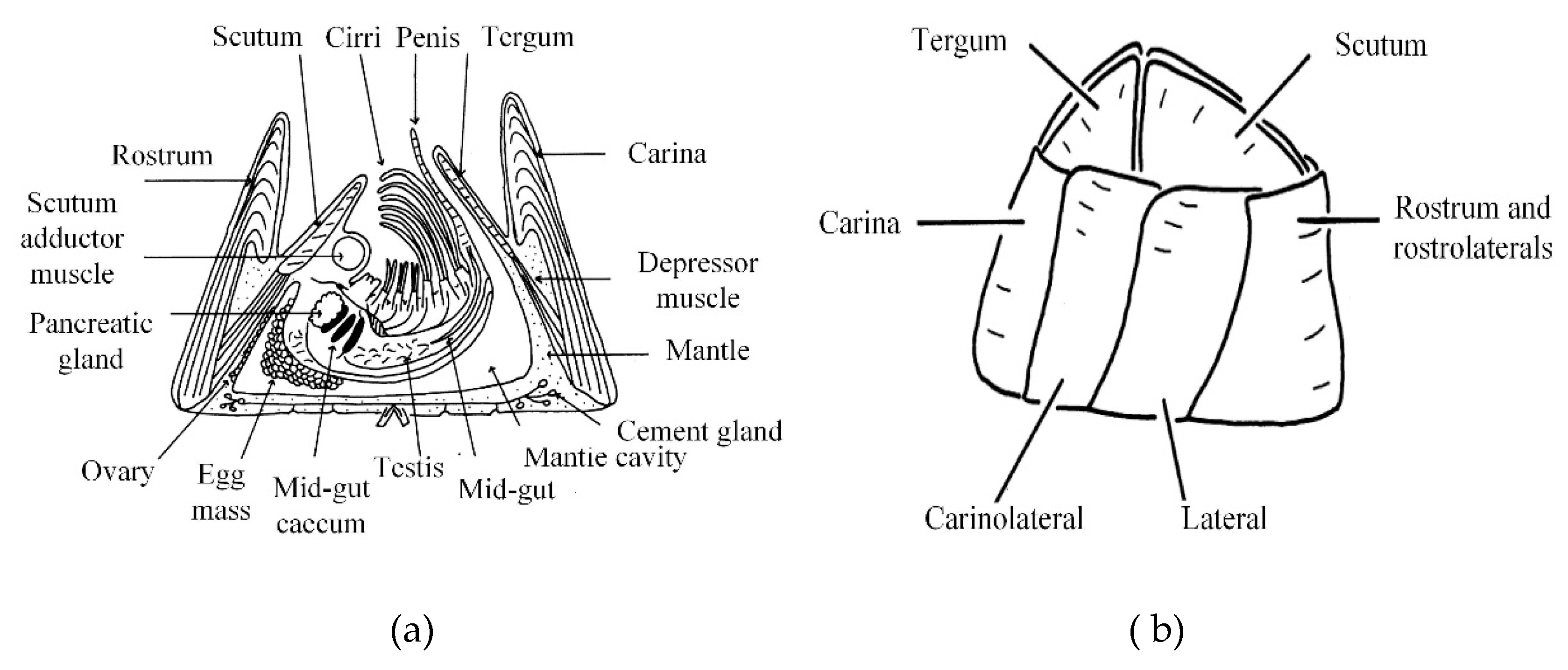
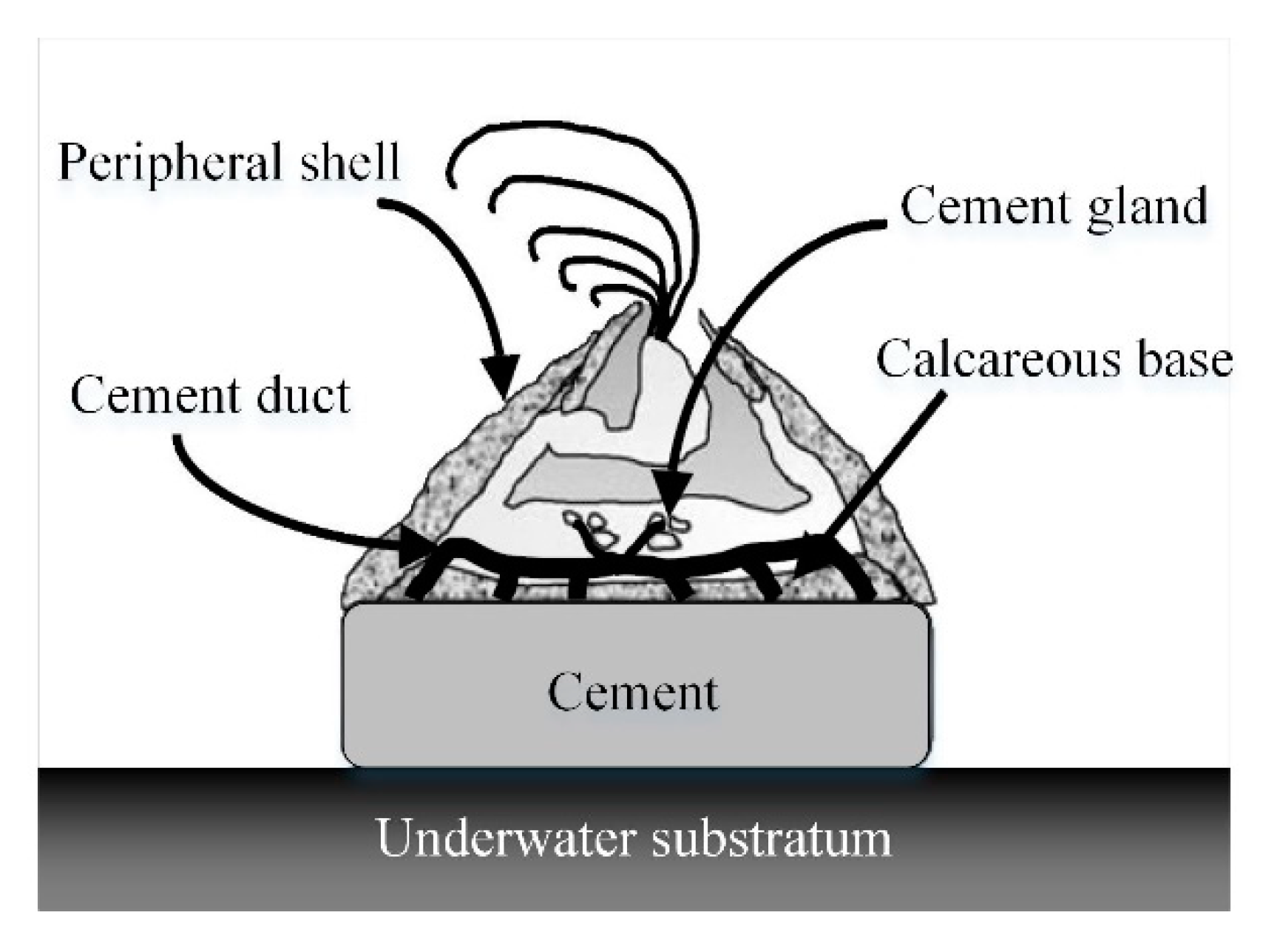
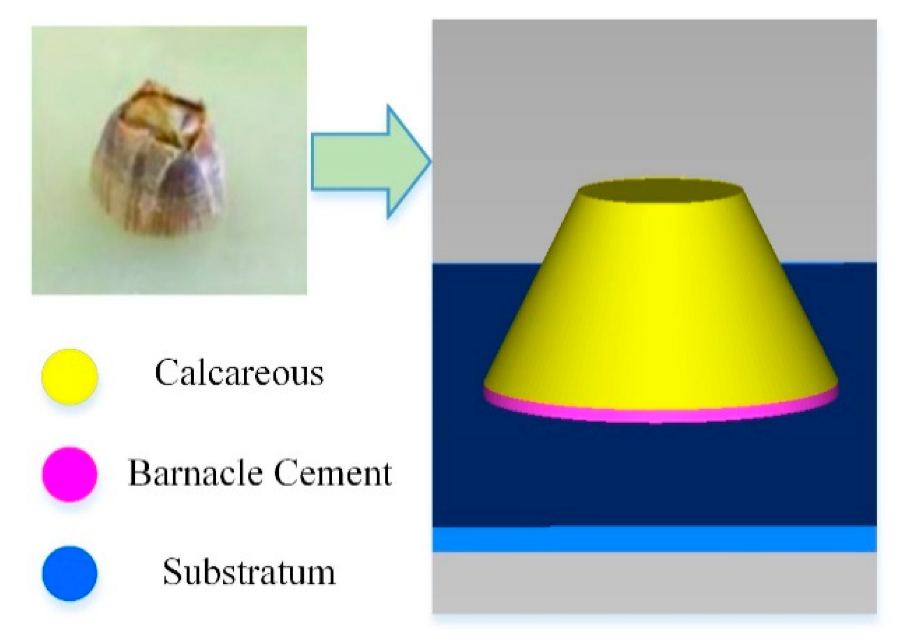
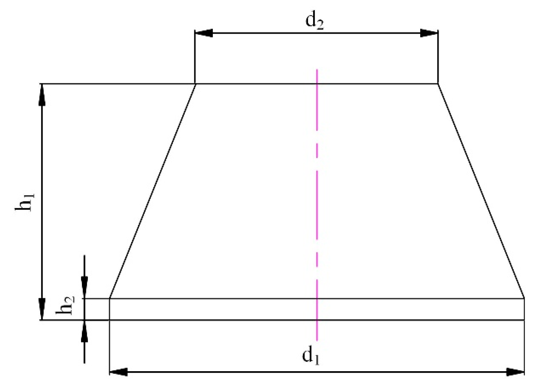
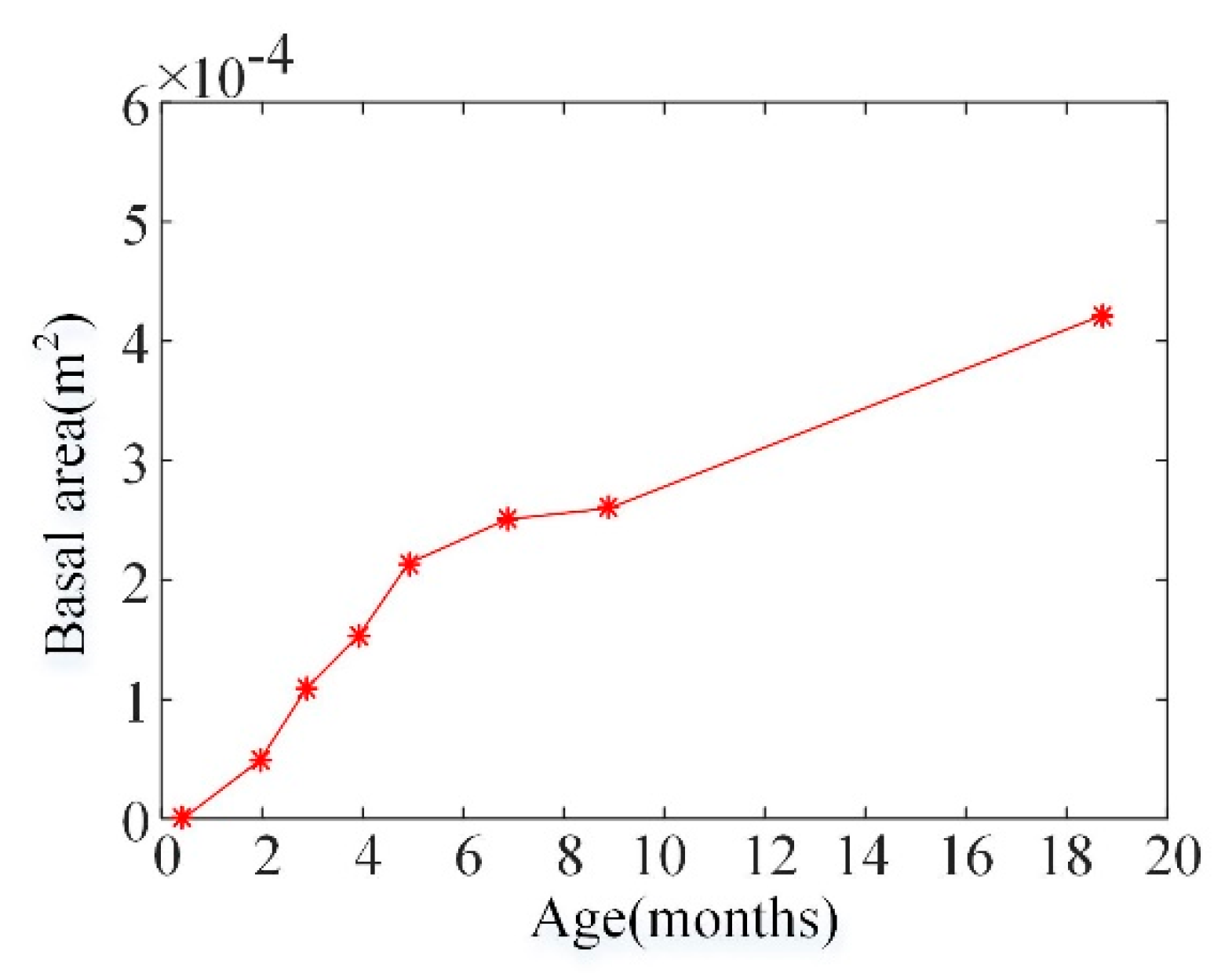
2. Barnacle Background and Model Analysis

The barnacle is the main sea creature responsible for fouling. Most barnacles live in the intertidal zone and attach to fixed or floating hard objects in the sea. It takes only a few months for the barnacle larvae (who make a temporary adhesion) to grow into shell-like adults. Barnacles employ a proteinaceous substance for underwater attachment. They secrete a liquid cement to ‘glue’ themselves to the substrate surface for permanent adhesion. Barnacle cement consists of more than 90% protein and is a multi-protein complex. Barnacle studies have suggested the significance of intermolecular interaction [26]. Four or six harder calcareous shells surround the barnacle from outside, as shown in Figure 1a,b [27]. The barnacle attachment to the substrate is performed by the cement that they secrete from their underside. The cement is sticky and insoluble in water. A cross-section of a barnacle attached to a substrate is shown in Figure 2, with the cement layer scaled in thickness [26].
Jadidi [28] presented a model consisting of a barnacle attached to a cylinder in order to analyze the effect of barnacles on cylindrical vortex-induced vibration. This model was an axisymmetric mound with a trapezoidal cross-section. Based on the previous model, in this research, the barnacle is ideal as it is an axisymmetric mound with a trapezoidal cross-section (calcareous) and has a round cushion (cement) on the bottom, as shown in Figure 3. The cement attaches to a rigid substrate plane.
The geometrical model’s bottom diameter is d1, the height average is 12 months, the barnacle is h1 = 5d1/12, the top diameter is d2 = 7d1/12, and the cement cushion height is h2 = d1/24, approximately, as shown in Figure 4.
The size/diameter of different kinds of barnacles varies from 8 to 43 mm [29]. Most of our information on barnacle growth relates to the Balanomorpha genus, and in particular, to Semibalanus balanoides (Previous name Balanus balanoides). S. balanoides is a sessile barnacle that attaches to hard substrates and is a widely-distributed intertidal species found on both sides of the North Atlantic and the eastern North Pacific [30,31]. This species has a highly synchronized settlement; therefore, a single cohort can be readily followed. It is relatively easy to measure the diameter and it has specific representativeness. Its adhesion force increases monotonously with the area and age of the S. balanoides attached, and the attachment area increases with time [32], as shown in Figure 5.

3. Removing Process and Methods

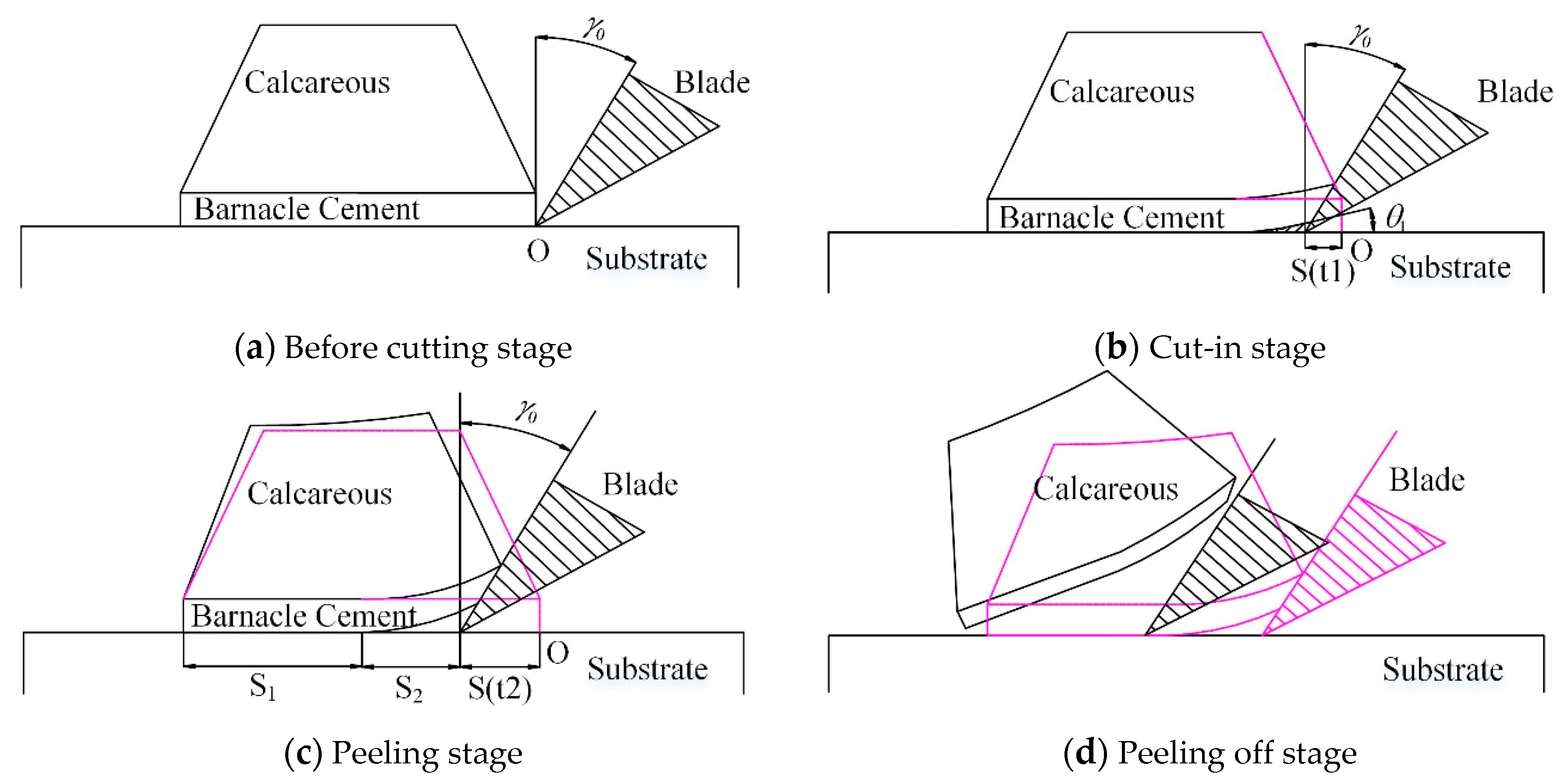
3.1. Analysis of Removing Process
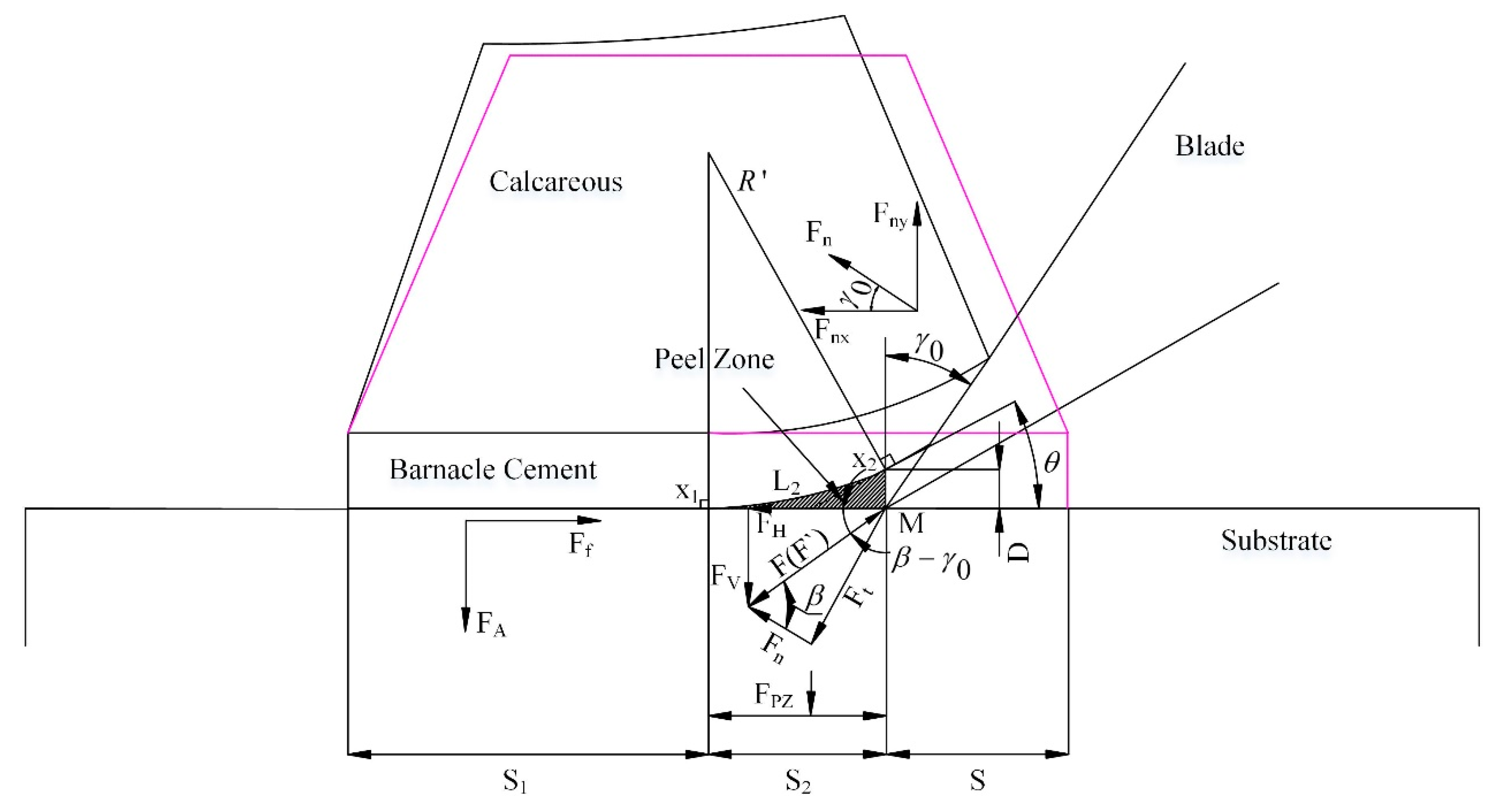
The barnacle was attached to the rigid substrate by cement. It was hard to remove it because the calcium shells strongly attached to the cement. In this paper, a scraping method was proposed to analyze the force required for barnacle cleaning, which combined the orthogonal cutting method and the peel zone method proposed by Pesika [33,34]. The process of scraping the barnacle was organized into four stages, as shown in Figure 6.
The first stage was the before-cutting stage. The blade with a rake angle of γ0 moved towards the barnacle at a certain speed until it engaged with the barnacle cement at point O.
The second stage was the cut-in stage. The blade cut into the cement from point O until the blade touched the calcareous shell at the moment of t1, with a displacement of S (t1), and a peel angle θ1 was produced.
The third stage was the peeling stage. The blade further moved to S(t2) at the moment of t2. The blade represented the normal and tangential forces of the shell. The normal force applied to the rake face was the main force that was applied to the barnacle—making the calcareous shell deform, gradually lift, and almost break away from the substrate. The remaining adhesion length was S1. The curved portion forms of the peel zone, with the corresponding length of S2, and d1 = S1+ S2 + S(t2), had a range of peel angles at 0° < θ ≤ 90°.
The fourth stage was the peeling-off stage. The total adhesion of the barnacle decreased, in addition to the force on the blade, as the blade kept moving until the barnacle was fully peeled away from the substrate.

3.2. Force Analysis

Scraping the barnacle that was attached to the substrate was, in some ways, similar to peeling-off the gecko spatula pad. Barnacle cement and gecko spatula pads are both viscoelastic materials that were attached to the substrate. However, the calcareous shell of the barnacle restricted the large deformation of the cement when the barnacle was peeled-off, which was the difference from peeling-off the gecko spatula pad. The calcareous shell deformed and lifted up after coming into contact with the blade’s surface. The peel zone could be formed in a similar way to the spatula pad peeling. The peel zone was the area where the cement was peeled-off from the substrate and some of the adhesive fibers still remained, as shown in Figure 7. The area enclosed by points x1, x2 and the tool-tip point M was the peeling area, corresponding to the horizontal distance S2. The vertical distance from x2 to the surface of the substrate was D, which was the critical distance; the adhesion failed at any point when the vertical distance to the substrate surface was larger than D. The other variables are defined in the next section. The adhesion force FA on the substrate could be analyzed and calculated according to the adhesion mechanism of the cement, and the adhesion force of the peel zone, FPZ, could be analyzed by Pesika’s peel zone method.

3.3. Force on Blade

The orthogonal cutting theory used the calculation from the second stage of the scraping. We can assume that the cutting edge of the blade was absolutely sharp, the flank face was not in contact with the substrate, and the friction of the flank face was zero [35,36]. Two forces were applied to the calcareous shell, as shown in Figure 7: the normal force Fn and the tangential friction force Ft, which are from the rake face and F is the resulting force. F′ was the counterforce of F and was equal in amplitude and opposite in direction. The counterforce F′ could be decomposed in the horizontal direction, FH, and the vertical direction, FV. β was the angle between F and Fn, and β-γ0 was the angle between F′ and FH.
The calcareous shell was deformed by the normal force Fn of the rake face and Fn could be decomposed into normal force Fnx and tangential force Fny. The following relationship applies:
F ny = F H cos β sin γ 0 cos ( β γ 0 ) ,
where β is also called the friction angle, and γ0 is the fake angle of the blade.

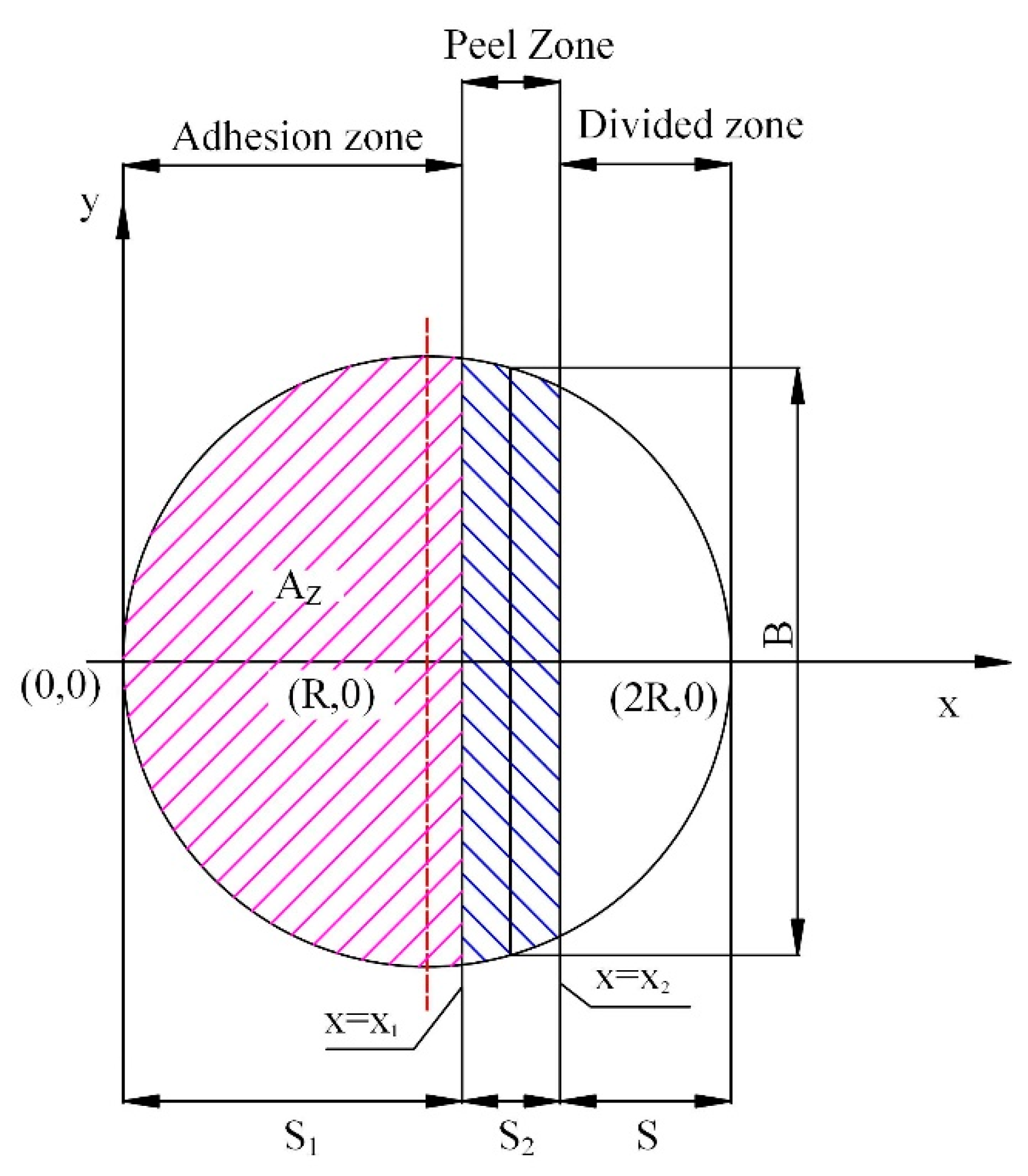
3.4. Adhesion Force in the Peel Zone

In the second stage, the barnacled bottom, with a radius of R, was composed of three zones: the divided zone, the peeling zone, and the adhesion zone, as shown in Figure 8. The pink shadow part was the adhesion zone with a length of S1, a normal adhesion force FA and a horizontal friction force Ff. The blue shadow was the peel zone with a length of S2 and an adhesion force FPZ. The amplitudes of FA and FPZ could be calculated individually.
The calcareous shell was deformed by the normal force of Fn on the rake face. Suppose that the bottom deformation of the shell is an arc with a radius of R′ and the cement deformation follows the calcium shell. When the cement was peeled off, the bottom surface kept the same arc and the arc length between x1 and x2 was L2. When θ was small, L2 = R′θ ≈ S2. The cement volume in the peel zone was enclosed by three points—x1, x2 and M. x1 is the contact point where the cement started to separate away from the substrate. x2 was the point at which the last fiber of cement was broken on the substrate. M was the blade tip. The angle between x1 and x2 was the peel angle, θ. According to the empirical formula, the relationship between R′ and θ was R′ = 4215 × θ−1.35 [34]. The width B in the peel zone between x1 and x2 was B = 2 R 2 ( R S ) 2 , as shown in Figure 8. The adhesion force of peel zone is:
F P Z = A R ( R 2 ( R S ) 2 ) 8 2 D 5 2 ,
where A is the Hamaker constant, D is the surface gap.
In Reference [33], the “gecko spatula pad is composed of β-keratin” and is a kind of protein. In Reference [26], “more than 90% of barnacle cement is composed of proteins and is a multi-protein complex”. In References [26,33,34], their adhesion mechanisms were all caused by intermolecular interactions, and the thickness of the gecko spatula pad and barnacle cement were of the same order of magnitude. Based on the above similarities, we also made assumptions that ensured that the empirical formulas were used to estimate the adhesion of the peel zone.
When S = 0.024 m, the relationship between the peeling angle and the adhesion force was as shown in Figure 9. The adhesive force decreased quickly when 0° < θ < 10° and gently when θ >20°.
When the blade moved from 0 to 0.024 m, the adhesive force in the peel zone, with a peel angle from 1° to 10°, was as shown in Figure 10. When S = 0.012 m, the adhesion force of the peel zone reached its maximum, and gradually reduced after that because its bottom projection was circular, as shown in Figure 8. As is known from Equation (2), the adhesion force of the peel zone was affected by the width B in the removal process; B first increased and then decreased, and reached the maximum at S = 0.012 m.
The area of the adhesion zone, AZ, as shown in Figure 8, is:
A Z = 2 0 x 1 R 2 ( X R ) 2 d X ,
where R = 0.012 m, AZ is expressed as:
A Z = 9 π 125000 + 9 arcsin ( 250 x 1 3 1 ) 62500 + 9 62500 ( x 1 3 250 ) 2 × ( x 1 3 250 ) ,
where S1 = d1 − S2 − S and S2 ≈ R′θ. The adhesion strength of the adult barnacle was P = 9.252 × 10⁵ N/m2 [26,32]. Suppose that the barnacles to be removed were more than one year old, in which case the remaining adhesion force FA can be expressed as follows:
F A = P × ( 9 π 125000 + 9 arcsin ( 250 ( 2 R R θ S ) 3 1 ) 62500 + 9 62500 ( ( 2 R R θ S ) 3 250 ) 2 × ( ( 2 R R θ S ) 3 250 ) ) ,
In the vertical direction, the following equation applies:
F ny = F A + F P Z ,
Substitute Equations (2) and (5) into (6) and, Fny can be rewritten as follows:
F ny = [ P × ( 9 π 125000 + 9 arcsin ( 250 ( 2 R R θ S ) 3 1 ) 62500 + 9 62500 ( ( 2 R R θ S ) 3 250 ) 2 × ( ( 2 R R θ S ) 3 250 ) ) ] + ( A 2 R 2 ( R S ) 2 ( R ) 1 2 16 2 D 5 2 ) ,
The adhesive force, with regard to the blade displacement, was as shown in Figure 11. The adhesive force was the maximum at the zero point where the blade did not cut in, and when the blade kept moving, the adhesion force decreased due to the adhesion area decreasing. When the blade displacement equaled the barnacle diameter, 2R, the adhesion force was 0 and the barnacle was fully removed.
Substitute Equations (1) into (7) and, FH can be expressed as:
F H = cos ( β γ 0 ) cos β sin γ 0 { [ P × ( 9 π 125000 + 9 arcsin ( 250 ( 2 R R θ S ) 3 1 ) 62500 + 9 62500 ( ( 2 R R θ S ) 3 250 ) 2 × ( ( 2 R R θ S ) 3 250 ) ) ] + ( A 2 R 2 ( R S ) 2 ( R ) 1 2 16 2 D 5 2 ) } ,
where A = 0.4 × 10⁻¹⁹ and R = 0.012 m. The maximum friction force corresponded to the peel angle, θ = 10°, and R′ = 4215 × θ −1.35 [34]. The friction coefficient of the cement on the substrate and the rake face of the blade was 0.25 [33], which corresponded to β = 14°. The cutting force FH, with respect to the blade displacement and the rake angle from 10° to 90°, is as shown in Figure 12.
The rake angle affects the cutting force FH and can also be plotted as a 3D surface, as shown in Figure 13. The blade rake angle had a significant effect on the cutting force. Reducing the rake angle could increase the cutting force considerably in the range of (0°–45°) and this trend was relatively gentle in the rake angle range of (45°–90°). The rake angle could be a compromise between the cutting force and blade strength/life cycle. The blade rake angle should be a medium one, such as [30°, 60°].
FV can be obtained with the same method:
F V = sin ( β γ 0 ) cos β sin γ 0 { [ P × ( 9 π 125000 + 9 arcsin ( 250 ( 2 R R θ S ) 3 1 ) 62500 + 9 62500 ( ( 2 R R θ S ) 3 250 ) 2 × ( ( 2 R R θ S ) 3 250 ) ) ] + ( A 2 R 2 ( R S ) 2 ( R ) 1 2 16 2 D 5 2 ) }
The cutting forces FH and FV, with a blade rake angle of 60°, are plotted in Figure 14. The absolutes of both FH and FV decreased as the blade kept moving until S = 0.024 m, where both cutting forces were 0 and the barnacle was fully removed. The adhesion force in the vertical direction was Fny = FA + FPZ = 419 N and the maximum horizontal cutting force was FH = 346 N.

4. Finite Element Analysis and Results

To verify the analytical model, 3D finite element models are created in Ls-dyna with Hypermesh, as shown in Figure 15. The barnacle size, d1, is 0.024 m in diameter. The height, cement thickness, and top diameter are calculated according to Figure 4. The blade rake angle was 60°. The blade velocity is 0.7 m/s. The solid element is used for the blade, barnacle shell and cement, and the substrate is set as the shell elements to minimize the computation load.
The material of the blade and substrate is elastic, the density is ρ = 7.93 × 10³ kg/m3, the bulk modulus of elasticity is K = 1.95 × 10⁵ MPa, and the Poisson’s ratio is γ = 0.247. Calcareous shell is a plastic material, the density is ρ = 2.6 × 10³ kg/m3, the bulk modulus of elasticity is K = 5 × 10⁴ Mpa, and the Poisson’s ratio is γ = 0.3; the material of the cement is viscoelastic, the density is ρ = 1.19 × 10³ kg/m3, and the bulk modulus of elasticity is K = 100 MPa. The model has meshed with 12,162 elements and 15,405 nodes in total.
The contact with a failure, CONTACT_AUTOMATIC_SURFACE_TO_SURFACE_TIEBREAK, is set between the cement and substrate; the contact (no failure), CONTACT_AUTOMATIC_SURFACE_TO_SURFACE, is set between the calcareous shell, cement, and blade. In total, four contact groups are set in this simulation. The friction between the flank face and the substrate is set as zero. The bottom substrate is set as fixed in six freedom degrees and the blade is set as -0.7 m/s in the x direction.
The adhesion forces of both simulation and analytical results are plotted in Figure 16 with respect to the blade displacement.
The trend of the analytical result from the adhesion force agrees with the trend exhibited for the simulation; the analytical result is a little lower than the simulation result in the full range of the blade displacement, as shown in Figure 16. The maximum and minimum errors occur at point A and B, with the maximum relative error of 14.7% at point A and the minimum relative error of 11.8% at point B. At point C, the relative error is 13.5%, which is between the maximum and the minimum values.
The analytical and simulation results of the cutting forces, FH and FV, are plotted in Figure 17. The trends of analytical results agree with the simulations. The analytical and simulation curves of the cutting force, FH, intersect at points D, E and F. The relative errors between them are less than 10%. The analytical and simulation results of the cutting force, FV, are in complete agreement at points of G and H. The maximum error occurs at the start point where S = 0. The error between the simulation and analytical results is the result of the assumption of the Peel Zone method, particularly the assumption of the arc section of the cement in the peel zone and the radius, R′, being considered as not being a constant but a function of S.

5. Conclusions

In this paper, on the basis of the orthogonal cutting theory and the peel zone method, an analytical model of the cutting forces is proposed to scrape barnacles with blades. On the basis of this analysis, the following conclusions can be drawn:
(1)
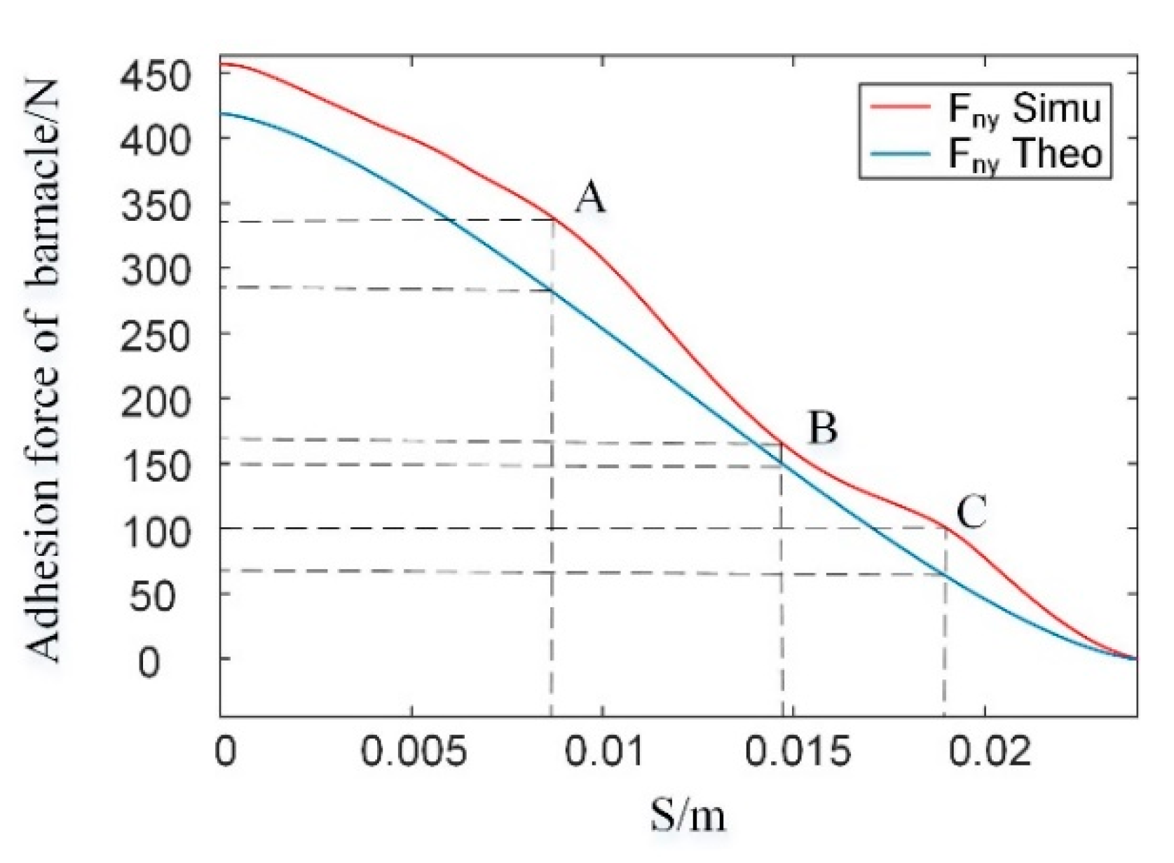
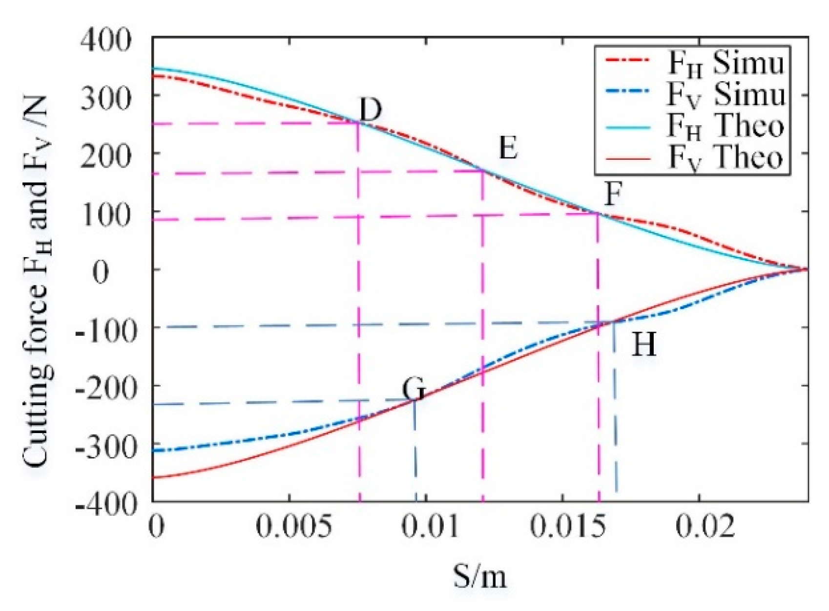
The analytical model is verified with a finite element simulation and the comparison shows the relative error of this model to be less than 10%. The model can be used to estimate the cutting force in barnacle scraping operation in order to support related equipment design.
(2)
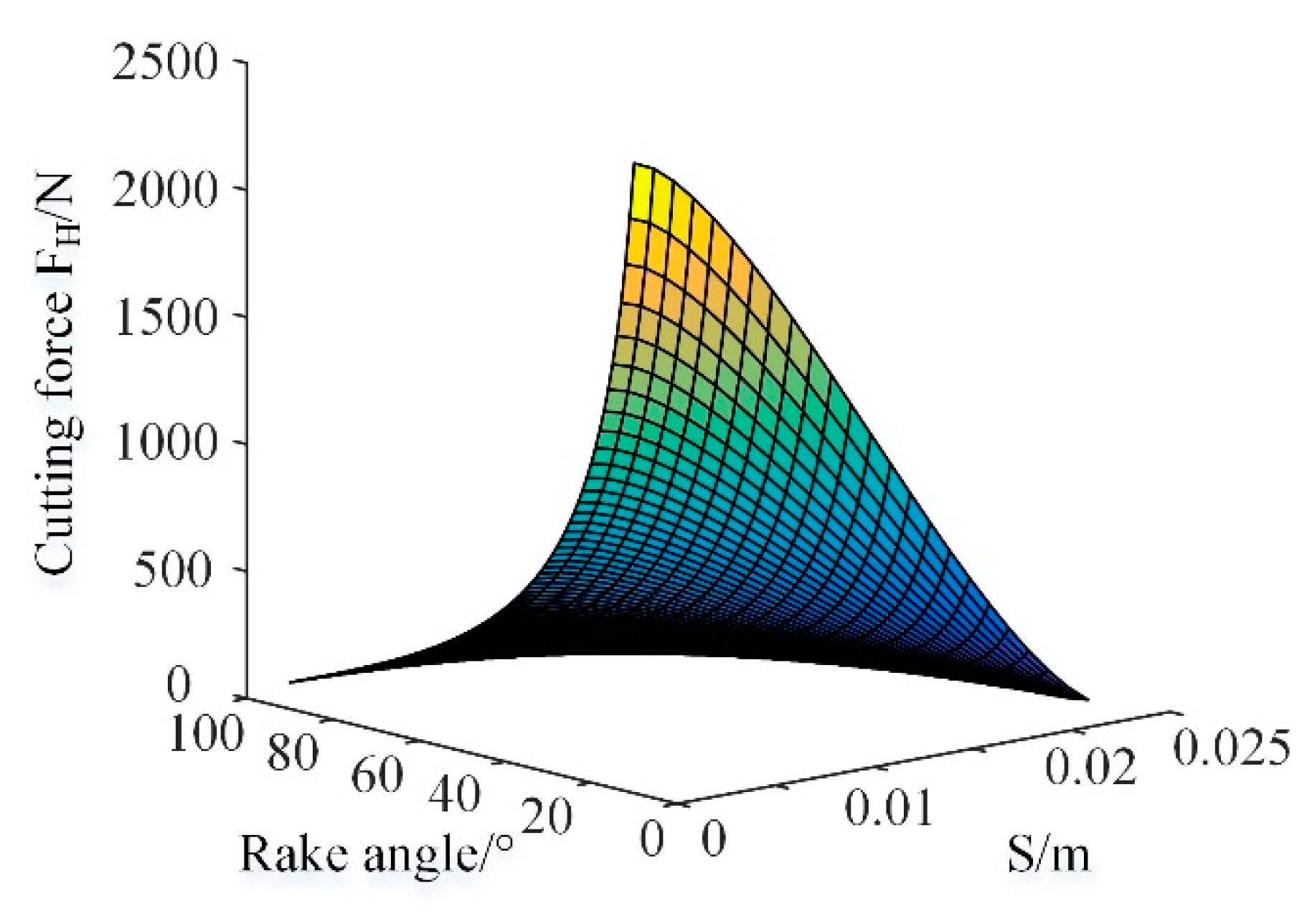
The blade rake angle has a significant effect on the cutting force. Reducing the rake angle can increase the cutting force considerably in the range of (0°–45°) and this trend is relatively gentle in the rake angle range of (45°–90°). The rake angle can be a compromise between cutting force and blade strength/life cycle. The conclusion can be drawn that the larger the blade rake angle, the smaller the cutting force required to remove the attached barnacle. The blade rake angle should be a medium one, such as [30°, 60°].
Further research will be carried out in the following areas: (1) barnacle size/age effects on the cutting force, (2) barnacle size/age-dependent material properties for the cement and shell, (3) rake angle and barnacle size/age effects on the peel angle, and (4) the error correction that poses a challenge to minimizing the model errors and coefficients, which can be introduced to correct the cutting forces and adhesion force with respect of the barnacle age/size.

Author Contributions

Formal analysis, C.L. and G.W.; Methodology, C.L.; Writing—original draft preparation, C.L., and G.W.; Writing—review and editing, K.C., F.Y. and L.W., Validation, K.C., L.W. and F.Y.; Supervision L.W.; Funding acquisition, G.W. and F.Y. All authors have read and agreed to the published version of the manuscript.

Funding

This research was funded by National Key Research and Development Project [Grant No. 2018YFF01012900], National Natural Science Foundation of China [Grant No. 51779059, 51409058, 61633009], Fundamental Research Funds for the Central Universities [Grant No. 3072019CF0705], China Postdoctoral Science Foundation [Grant No. 2018M630343], and Science and Technology on Underwater Vehicle Laboratory [Grant No. 614221503041701].

Acknowledgments

The authors gratefully acknowledge the financial support from National Key Research and Development Project [Grant No. 2018YFF01012900], National Natural Science Foundation of China [Grant No. 51779059, 51409058, 61633009], Fundamental Research Funds for the Central Universities [Grant No. 3072019CF0705], China Postdoctoral Science Foundation [Grant No. 2018M630343], and Science and Technology on Underwater Vehicle Laboratory [Grant No. 614221503041701].

Conflicts of Interest

The authors declare no conflict of interest.

References

  1. Yebra, D.M.; Kiil, S.; Dam-Johansen, K. Antifouling technology—Past, present and future steps towards efficient and environmentally friendly antifouling coatings. Prog. Org. Coat. 2004, 50, 75–104. [Google Scholar] [CrossRef]
  2. Zhang, D.; Gao, X.; Su, G.; Du, L.; Liu, Z.; Hu, J. Corrosion Behavior of Low-C Medium-Mn Steel in Simulated Marine Immersion and Splash Zone Environment. J. Mater. Eng. Perform. 2017, 26, 2599–2607. [Google Scholar] [CrossRef]
  3. Azis, P.K.A.; Al-Tisan, I.; Al-Daili, M.; Green, T.N.; Ba-Mardouf, K.; Al-Qahtani, S.A.; Al-Sabai, K. Marine macrofouling: A review of control technology in the context of an on-line experiment in the turbine condenser water box of Al-Jubail Phase-I power MSF plants. Desalination 2003, 154, 277–290. [Google Scholar] [CrossRef]
  4. Amoozadeh, E.; Malek, M.; Rashidinejad, R.; Nabavi, S.; Karbassi, M.; Ghayoumi, R.; Ghorbanzadeh-Zafarani, G.; Salehi, H.; Sures, B. Marine organisms as heavy metal bioindicators in the Persian Gulf and the Gulf of Oman. Environ. Sci. Pollut. R. 2014, 21, 2386–2395. [Google Scholar] [CrossRef] [PubMed]
  5. Bram, J.B.; Page, H.M.; Dugan, J.E. Spatial and temporal variability in early successional patterns of an invertebrate assemblage at an offshore oil platform. J. Exp. Mar. Biol. Ecol. 2005, 317, 223–237. [Google Scholar] [CrossRef]
  6. Sell, D. Marine fouling. P. Roy. Soc. Edinb. Sec. B Biol. Sci. 1992, 100, 169–184. [Google Scholar] [CrossRef]
  7. Kavanagh, C.J.; Schultz, M.P.; Swain, G.W.; Stein, J.; Truby, K.; Wood, C.D. Variation in adhesion strength of Balanus eburneus, crassostrea virginica and hydroides dianthusto fouling-release coatings. Biofouling 2001, 17, 155–167. [Google Scholar] [CrossRef]
  8. Wendt, D.E.; Kowalke, G.L.; Kim, J.; Singer, I.L. Factors that influence elastomeric coating performance: The effect of coating thickness on basal plate morphology, growth and critical removal stress of the barnacle Balanus amphitrite. Biofouling 2006, 22, 1–9. [Google Scholar] [CrossRef] [Green Version]
  9. Aldred, N.; Clare, A.S. The adhesive strategies of cyprids and development of barnacle-resistant marine coatings. Biofouling 2008, 24, 351–363. [Google Scholar] [CrossRef]
  10. Aldred, N.; Scardino, A.; Cavaco, A.; de Nys, R.; Clare, A.S. Attachment strength is a key factor in the selection of surfaces by barnacle cyprids (Balanus amphitrite) during settlement. Biofouling 2010, 26, 287–299. [Google Scholar] [CrossRef]
  11. Scardino, A.J.; de Nys, R. Mini review: Biomimetic models and bioinspired surfaces for fouling control. Biofouling 2011, 27, 73–86. [Google Scholar] [CrossRef] [PubMed]
  12. Dolez, P.I.; Love, B.J. Acid cleaning solutions for barnacle-covered surfaces. Int. J. Adhes. Adhes. 2002, 22, 297–301. [Google Scholar] [CrossRef]
  13. Nassiraei, A.A.F.; Sonoda, T.; Ishii, K. Development of Ship Hull Cleaning Underwater Robot. In Proceedings of the 2012 Fifth International Conference on Emerging Trends in Engineering and Technology, Himeji, Japan, 5–7 November 2012. [Google Scholar]
  14. Souto, D.; Faina, A.; Lopez-Pena, F.; Duro, R.J. Lappa: A New Type of Robot for Underwater Non-Magnetic and Complex Hull Cleaning. In Proceedings of the 2013 IEEE International Conference on Robotics and Automation, Karlsruhe, Germany, 6–10 May 2013. [Google Scholar]
  15. Ross, B.; Bares, J.; Fromme, C. A semi-autonomous robot for stripping paint from large vessels. Int. J. Robot. Res. 2003, 22, 617–626. [Google Scholar] [CrossRef]
  16. Narewski, M. Hismar-Underwater Hull Inspection and Cleaning System as a Tool for Ship Propulsion System Performance Increase. J. Pol. CIMAC 2009, 4, 227–232. [Google Scholar]
  17. Bar-Cohen, Y.; Bao, X.; Dolgin, B.P.; Marzwell, N.I. Residue Detection for Real-Time Removal of Paint from Metallic Surfaces. In Proceedings of the 6th Annual International Symposium on NDE for Health Monitoring and Diagnostics, Newport Beach, CA, USA, 4–8 March 2001; Volume 4335. [Google Scholar]
  18. Yi, Z.; Gong, Y.; Wang, Z.; Wang, X. Development of a Wall Climbing Robot for Ship Rust Removal. In Proceedings of the International Conference on Mechatronics & Automation, Changchun, China, 9–12 August 2009. [Google Scholar]
  19. Yamada, J.; Takiguchi, T.; Saito, A.; Odanaka, H.; Soyama, H.; Yamamoto, M. Removal of Oral Biofilm on an Implant Fixture by a Cavitating Jet. Implant. Dent. 2017, 26, 904–910. [Google Scholar] [CrossRef] [PubMed]
  20. Guo, S.; Khoo, B.C.; Teo, S.L.; Lee, H.P. The effect of cavitation bubbles on the removal of juvenile barnacles. Colloid. Surface B Biointerfaces 2013, 109, 219–227. [Google Scholar] [CrossRef]
  21. Omel’yanyuk, M.V. Removal of Growths and Incrustations from Water-Development Works. Power Technol. Eng. 2013, 47, 239–243. [Google Scholar] [CrossRef]
  22. Murakawa, M.; Takeuchi, S. Quantitative adhesion strength measurement of diamond coatings. Thin Solid Films 1989, 181, 443–450. [Google Scholar] [CrossRef]
  23. Xie, Z.; Zhu, J. The effect of the vertical load on the scraping test. Thin Solid Films 1998, 315, 192–194. [Google Scholar] [CrossRef]
  24. Xie, Z.; Zhu, J.; Guo, W. The Scraping Test and Adhesion Measurements of Diamond and Nickel Electroless Coatings. Mater. Charact. 2000, 44, 347–352. [Google Scholar] [CrossRef]
  25. Kaneko, K. Evaluation of the Shearing Strength of a WC-12Co Thermal Spray Coating by the Scraping Test Method. Coatings 2015, 5, 278–292. [Google Scholar] [CrossRef] [Green Version]
  26. Smith, D.A.M.; Callow, D.J.A. Biological Adhesives, 1st ed.; Springer: Berlin, Germany, 2006; pp. 145–152. [Google Scholar]
  27. Rainbow, P.S. An introduction to the biology of British littoral barnacles. Field Stud. 1984, 6, 1–51. [Google Scholar]
  28. Jadidi, P.; Zeinoddini, M.; Soltanpour, M.; Zandi, A.P.; Seif, M.S. Towards an understanding of marine fouling effects on VIV of circular cylinders: Aggregation effects. Ocean. Eng. 2018, 147, 227–242. [Google Scholar] [CrossRef]
  29. Crisp, D.J.; Bourget, E. Growth in Barnacles. Adv. Mar. Biol. 1985, 22, 199–244. [Google Scholar]
  30. Rognstad, R.L.; Wethey, D.S.; Oliver, H.; Hilbish, T.J. Connectivity modeling and graph theory analysis predict recolonization in transient populations. J. Mar. Syst. 2018, 183, 13–22. [Google Scholar] [CrossRef]
  31. Rognstad, R.L.; Hilbish, T.J. Temperature-induced variation in the survival of brooded embryos drives patterns of recruitment and abundance in Semibalanus balanoides. J. Exp. Mar. Biol. Ecol. 2014, 461, 357–363. [Google Scholar] [CrossRef] [Green Version]
  32. Yule, A.B.; Walker, G. The Adhesion of the Barnacle, Balanus Balanoides, to Slate Surfaces. J. Mar. Biol. Assoc. UK 2009, 64, 147–156. [Google Scholar] [CrossRef]
  33. Pesika, N.S.; Tian, Y.; Zhao, B.; Rosenberg, K.; Zeng, H.; McGuiggan, P.; Autumn, K.; Israelachvili, J.N. Peel-zone model of tape peeling based on the gecko adhesive system. J. Adhesion 2007, 83, 383–401. [Google Scholar] [CrossRef] [Green Version]
  34. Yu, T.; Noshir, P.; Hongbo, Z.; Kenny, R.; Boxin, Z.; Patricia, M.G.; Kellar, A.; Jacob, I. Adhesion and friction in gecko toe attachment and detachment. Proc. Natl. Acad. Sci. USA 2006, 103, 19320–19325. [Google Scholar]
  35. Merchant, M.E. Mechanics of the Metal Cutting Process. I. Orthogonal Cutting and a Type 2 Chip. J. Appl. Phys. 1945, 16, 267–275. [Google Scholar] [CrossRef]
  36. Merchant, M.E. Mechanics of the Metal Cutting Process. II. Plasticity Conditions in Orthogonal Cutting. J. Appl. Phys. 1945, 16, 318–324. [Google Scholar] [CrossRef]
Figure 1. Anatomic structure (a) and 3D profile (b) of barnacle.
Jmse 08 00150 g001
Figure 2. The cross-section of a barnacle on a foreign substratum.
Jmse 08 00150 g002
Figure 3. The cross-section of a barnacle on a foreign substratum.
Jmse 08 00150 g003
Figure 4. Barnacle geometrical model and dimensions.
Jmse 08 00150 g004
Figure 5. Bottom area of S. balanoides with age.
Jmse 08 00150 g005
Figure 6. Schematic diagram of cleaning the barnacle process.
Jmse 08 00150 g006
Figure 7. Detailed analysis of the barnacle.
Jmse 08 00150 g007
Figure 8. Zones definitions in the second stage of the barnacle scraping.
Jmse 08 00150 g008
Figure 9. The adhesion force of the peel zone at different angles θ.
Jmse 08 00150 g009
Figure 10. Adhesion force of the peel zone vs blade displacement, S, with peel angle from 1° to 10°.
Jmse 08 00150 g010
Figure 11. Adhesion force vs blade displacement with barnacle diameter d1 = 0.24 mm.
Jmse 08 00150 g011
Figure 12. The cutting force Fc with the blade displacement from 0 to 0.024 m and the rake angle from 10° to 90°.
Jmse 08 00150 g012
Figure 13. 3D surface of the cutting force FH with the blade displacement from 0 to 0.024 m and the rake angle from 10° to 90°.
Jmse 08 00150 g013
Figure 14. The 60° rake angle of the blade corresponded to the cutting force FH and FV.
Jmse 08 00150 g014
Figure 15. The simulation diagram of barnacle.
Jmse 08 00150 g015
Figure 16. Simulation and analytical results of barnacle adhesion force.
Jmse 08 00150 g016
Figure 17. Analytical and simulation results of the cutting forces FH and FV.
Jmse 08 00150 g017

