Article

A Simple Superposition Formulation to Predict the Underwater Electric Potential Signature of Naval Vessels

1
General and Theoretical Electrical Engineering (ATE), University of Duisburg–Essen, and CENIDE—Center for Nanointegration Duisburg–Essen, D-47048 Duisburg, Germany
2
Technical Center for Ships and Naval Weapons, Naval Technology and Research (WTD71), Bundeswehr, D-24340 Eckernförde, Germany
*
Author to whom correspondence should be addressed.
J. Mar. Sci. Eng. 2020, 8(2), 105; https://doi.org/10.3390/jmse8020105
Submission received: 17 January 2020 / Revised: 4 February 2020 / Accepted: 6 February 2020 / Published: 10 February 2020
(This article belongs to the Section Ocean Engineering)

Abstract

:
The underwater electric potential (UEP) signature is an electric signal, which can be exploited by naval mines to be utilized as a possible trigger indicator and may cause severe damage to the vessel and the onboard crew. Hence, knowing the UEP signature as exactly as possible can help to evaluate a possible risk of the vessel being detected by naval mines or if the UEP signature is within a noncritical region. As the UEP signature differs for changes of the corrosion protection system, the UEP signature is usually unknown for new conditions. In this work, we present a simple mathematical formulation to predict the UEP signature based on the mere use of a single reference UEP signature, and the corresponding currents, which are excited by the impressed current cathodic protection (ICCP) system. With this methodology, deviations below 10% between the maximum of the simulated UEP signature and the predicted UEP signature can be achieved, even in the presence of the nonlinear corrosion process. Furthermore, a corrosion protective coating of the propellers can significantly reduce the influence of the nonlinear corrosion process on the total UEP signature to improve the prediction accuracy of the superposition formulation as presented in this work.

1. Introduction

In the fabrication process of naval vessels, different metallic materials are used. When these materials are galvanically connected and placed inside the seawater an electric current density will occur, which flows from the less noble metallic material to the more noble metallic material through the seawater. Here, the less noble material acts as the anode, the more noble material acts as the cathode and the seawater functions as the electrolyte. In contrast to a galvanic process where a transport of mass through the seawater from the anode to the cathode occurs, an oxidation process is present at the anode with the anodic partial reaction:
Me ( s ) Me n + ( aq ) + n e .
Here, Me represents a metallic material in the solid state (s) and the aqueous state (aq). The generated metal ions are not transported towards the cathode and the oxygen corrosion (reduction) will occur as the cathodic partial reaction formulated as
O 2 + 2 H 2 O + 4 e 4 OH ,
with the electrons in Equation (2) being generated within the hull by the oxidation formulation represented by Equation (1) and than flowing through the hull towards the cathode. In case of naval vessels the hull is commonly the less noble material compared to the propeller, thus leading to the corrosion of the hull, which may result in severe damage of the naval vessel. Due to the electric conductivity of the seawater and the aforementioned current density through the seawater an electric field can be defined, which is known as the underwater electric potential (UEP), representing the electric signature of naval vessels. To prevent a vessel from corrosion various protection systems can be installed on the vessel, that can be subdivided into passive and active corrosion protection systems. The coating of the hull is defined as the passive protection system and the active system can be further subdivided in the sacrificial anode cathodic protection (SACP) system and the impressed current cathodic protection (ICCP) system. In case of the SACP system a material less noble (in comparison to the hull) is galvanically connected to the hull, thus protecting the hull from corrosion while enforcing the hull material in the cathodic regime, while the oxidation process from (1) at the sacrificial anodes is present. For the ICCP system highly corrosion-resistant electrodes are used to actively impress anodic currents inside the seawater mimicking the behavior of a sacrificial anode to protect the hull from corrosion. Here, a new chemical reaction at the ICCP anodes occurs, which oxidates the chloride ions to chlorine described in the following reaction
2 Cl Cl 2 + 2 e .
The generated chlorine causes damage to the coating of the naval vessel and hence, an insulating shield is installed around the ICCP electrodes to suppress the oxidation process close to the anodes. When properly designed, each system is capable of protecting a naval vessels’ hull from corrosive damage but the main drawback of these systems lies within the additional current density, which is generated by the corrosion protection system itself. This current density causes an additional electric field, which may increase the total UEP signature of the naval vessel. As the UEP signature can be used as a possible trigger indicator for naval mines, it is necessary to describe said signature as accurate as possible to estimate the risk of possible detection. Measuring the UEP signature at a specific measurement site gives insight in the shape and the maximum value of the UEP signature for given environmental conditions at said location but the UEP signature may alter significantly when the environmental conditions or the impressed currents of the corrosion protection system are changing and hence, the accurate prediction of the UEP signature is aggravated. Usually, to model the UEP signature of naval vessels inverse modeling based on the particle swarm optimization (PSO) [1] is used where multiple point-electrodes are positioned within the model of the naval vessel to adapt a known UEP signature at a specific depth below the vessel [2]. However, it could be shown that even without inverse modeling, UEP signature predictions for various environmental conditions using simple mathematical formulations are feasible [3,4,5]. In this work, we will focus on the changes of the impressed currents of the onboard ICCP system of a numerical ship model to predict the UEP signature using a simple superposition relation based on the present ICCP currents and a reference UEP signature when the corrosion protection condition of the naval vessel is met. Here, the possibility of superimposing single UEP signatures even though nonlinear UEP signatures generated by the corrosion process are involved as shown. Finally, the presented methodology helps to estimate the risk of possible vessel detection for various materials when the ICCP currents change and improve the understanding of nonlinear corrosion processes for different metallic materials.

2. Numerical Setup

For the numerical evaluation a generic ship model including active as well as passive corrosion protection systems is implemented in the finite-element method (FEM) solver COMSOL Multiphysics [6]. All simulations were performed using the COMSOL version 5.4.0.388 and the electric currents (ec) physics within the AC/DC module. Furthermore, the direct solver Pardiso was utilized due to the usually fast and accurate numerical results for stationary calculations to solve the following model with approximately 390.000 degrees of freedom (DoF). The finite elements were chosen as tetrahedrons using quadratic functions and the computational time for each simulation took approximately 10 s on a standard PC with an i7-6700K and 64 GB of RAM.

2.1. Ship Model

The generic ship model has a length of 50 m, a width of 9 m and a draught of 4 m and is equipped with a four-zone ICCP system. Additionally, an SACP is installed inside the sea chests and the stern region of the ship, which are represented by circular patches with a diameter of 40 cm. The benefit of combining the ICCP with the SACP system is to smoothen the electric potential distribution over the hull, while ensuring the corrosion protection condition with lower ICCP currents. However, due to the strong gradients of the electric potential in close vicinity to the ICCP electrodes, a circular electric insulation with a diameter of 1.5 m is positioned around each electrode to prevent overprotection in said regions. For further clarification, the ship model is depicted in Figure 1.

2.2. Governing Equations

The physics underlying the ec module uses the following equations for a stationary evaluation to calculate the scalar field of the electric potential V as the dependent variable
· J = Q j , v
J = σ E + J e
E = V ,
with the undefined variables, which are the electric current density J , the current source Q j , v , which is an equivalent to the negative temporal derivate of the charge density, the electric conductivity σ , the electric field E and the external current density J e .

2.3. Computational Domain and Boundary Conditions

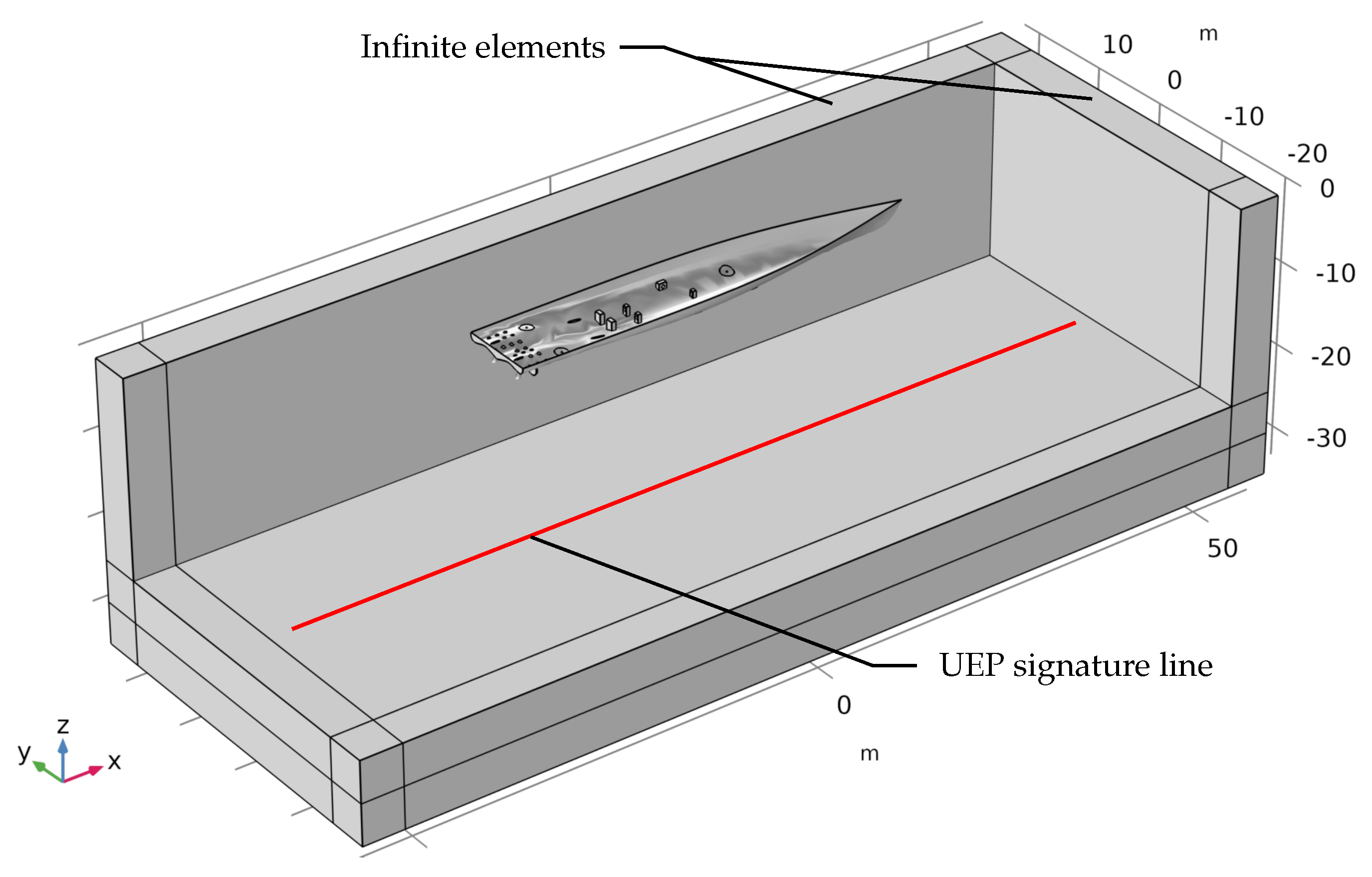
The ship model from Section 2.1 is positioned inside a box with a corresponding width of 110 m, a depth of 40 m and a height of 24.5 m, representing the water domain, as displayed in Figure 2. To account for the presence of the seabed another domain with the same width and depth but with a height of 5 m is placed below the water domain to achieve a total height of the water plus seabed domain of 29.5 m. For extracting the UEP signature of the naval vessel a UEP signature line (red line) is defined midship 20 m below the keel.
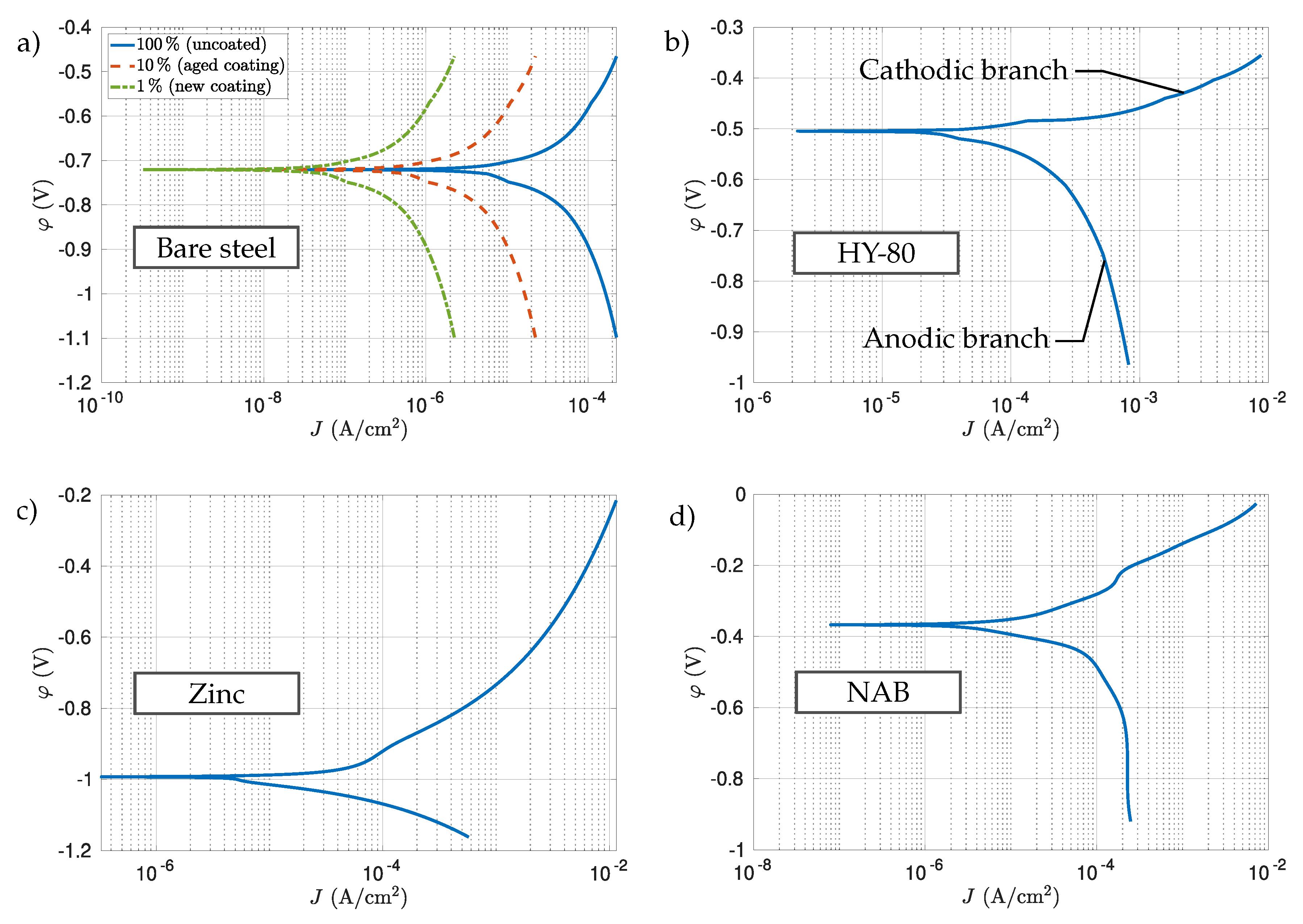
Furthermore, all boundaries except the top layer of the water domain are surrounded by infinite elements with a layer thickness of 5 m to mimic a virtually infinite region. For the boundary conditions of the computational model real polarization data taken from [7] were implemented in the numerical setup. For the reference electrode a silver/silver chloride (Ag/AgCl) electrode was chosen and all polarization curves were recalculated when the reference electrode in the literature differed from the Ag/AgCl electrode. For the ship’s hull and the sea chests bare steel [8], as well as a high yield steel (HY-80) [9] are taken into account, with the latter being commonly used in the ship or submarine fabrication process. For the propellers, the polarization curve of nickel-aluminum bronze (NAB) [10] is chosen and for the SACP system the polarization curve of zinc [11] is applied in the simulation. Finally, all the utilized polarization curves are presented in Figure 3.
To account for an imperfect coating of the ship model only a fraction of the current density of the polarization data is applied to the hull for bare steel and the HY-80 steel, respectively. In case of a new coating only 1% of the current density is considered, which approximates homogeneous coating damage of 1%. Accordingly, 100% of the polarization curve represents a totally uncoated area of the ship. In this work, all simulations are performed with a 5% coating damage of the hull for bare steel, as well as the HY-80 steel and the sea chests are simulated with a coating damage of 1%, due to the unlikeliness of facing direct damage from impacts. The propellers are considered to be uncoated as a first scenario and will receive a coating for the second scenario, with both scenarios explained in more detail in Section 3. The zinc anodes for the SACP system are simulated as completely uncoated and no passivation effects are taken into account, thus 100% of the zinc polarization curve is applied and finally, for the ICCP system an anodic current density is impressed inside the seawater. Within COMSOL, impressing the currents for the polarization curves and the ICCP electrode can be realised using the Inward Current Density boundary condition formulation
J n = n · J ,
with n being the unit vector normal to the surface and J n representing the normal current density. For positive values of J n the current density J will flow out of the ICCP electrode, thus an anodic current density is impressed inside the water domain.

3. Results

For the superposition of UEP signatures three different scenarios were simulated using the bare steel polarization curve (Figure 3a) for the hull and sea chests as the first scenario, the HY-80 polarization curve (Figure 3b) for both hull and sea chests as the second scenario and as the third scenario a corrosion protective coating for both propellers with the hull and sea chest material being bare steel. Coating the propeller can significantly reduce the ICCP current demand for corrosion protection up to 76% [12], which was measured on a sea trial. This lower demand of ICCP current leads to major reductions of the UEP signature, which is beneficial to lower the risk of possible detection of the vessel, as well as suppressing the nonlinear corrosion process, with the latter aggravating the superposition formulation of UEP signatures. For all cases, a reference scenario where the hull is protected against corrosion is necessary to predict the UEP signature when the impressed currents of the ICCP system are subject to potential change. For the protected case the required ICCP currents as well as the corresponding UEP signature generated by each ICCP electrode are extracted below the vessel. It is worth mentioning that for a real ship both values could be accessed either by the onboard monitoring system (for the ICCP currents) or when using measurements below the vessel at a corresponding measurement site (for the UEP signature).

3.1. Reference Scenario

For the reference scenario the electric conductivity of the water domain is set to 3 S/m and for the seabed layer a value of 0.5 S/m is chosen as these values approximately correspond to the environmental conditions of the measurement site in Aschau, Germany.
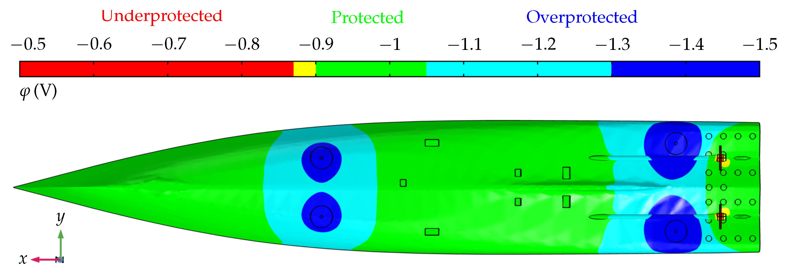
To find the necessary ICCP currents for corrosion protection the impressed currents are adjusted manually for all four ICCP electrodes until the corrosion protection condition is met. The appropriate corrosion protection potential was calculated for both bare steel and HY-80 steel using the corresponding German standard for corrosion protection of naval vessels [13]. In Figure 4 an exemplary electric surface potential distribution for bare steel is presented for corrosion protection of the full ship model. For the impressed currents of the bow electrodes, further described as I bp for the portside electrode and I bs for the starboard site, the current for both electrodes was set to I bp = I bs = 9 A and for the stern electrodes the values are set to I sp = I ss = 15 A . For the HY-80 steel the impressed currents needed to be significantly higher and a current of 35 A is needed for all four ICCP electrodes to fulfill the corrosion protection condition. Additionally, the UEP signature is extracted for corrosion protection and both, the impressed ICCP currents and the corresponding UEP signature for corrosion protection are used as a reference scenario for each hull material.

3.2. Superposition of UEP Signatures

For the aforementioned nonlinear corrosion process of naval vessels and the corresponding UEP signature a direct superposition of single UEP signatures will lead to deviations between the predicted UEP signature and the simulated signature. Considering the additional UEP signature generated by the ICCP system, which may yield in stronger maximum values of the signature, can dominate the nonlinear UEP signatures of the corrosion process. Hence, if the ICCP currents are strong enough to generate the more dominant UEP signature with respect to the corrosion process, a superposition of single UEP signatures is possible due to the linear correlation of the ICCP currents and the corresponding UEP signature. For clarification of the dominating UEP signature generated by the ICCP system, a superposition formulation of single UEP signatures is presented, which uses the impressed current density generated by each ICCP electrode and the corresponding UEP signature generated by each ICCP electrode to predict the total UEP signature. Ideally, the superimposed single UEP signature data are equivalent to the total UEP signature when all four ICCP electrodes are simultaneously active. Formally, the predicted values of the UEP signature are defined as follows for each electric field component:
E x , pred = i = 1 N ( E x , ref , i E x , corr ) · I i I ref + E x , corr
E y , pred = i = 1 N ( E y , ref , i E y , corr ) · I i I ref + E y , corr
E z , pred = i = 1 N ( E z , ref , i E z , corr ) · I i I ref + E z , corr .
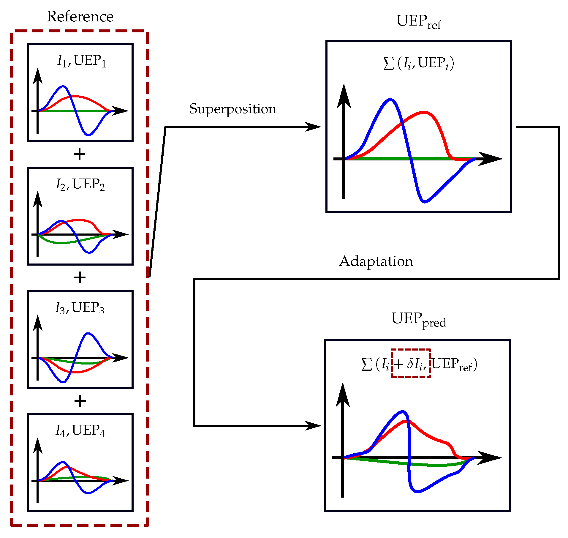
Here, the predicted UEP signature E pred is calculated using the sum over i of all single UEP signature reference data generated by each ICCP electrode for the total number of ICCP electrodes N. The UEP signature E corr , which was solely generated by the corrosion process can be extracted simulating the ship model with all ICCP currents set to 0 A (ICCP system is switched off) to isolate the corrosive reaction. When superimposing single UEP signatures the corrosion UEP signature would be taken into account N number of times in the shown formulation, due to the presence of the corrosion reaction when operating the ICCP system in a single electrode configuration, as well as operating multiple electrodes of the ICCP system simultaneously. Hence, the corrosion UEP signature is subtracted from each component in dependence of the number of electrodes and than added once to the equation to consider only a single UEP signature generated by the corrosion process. Furthermore, to predict the changes of the UEP signature for different ICCP currents the information of the present ICCP current at each ICCP electrode I i and the reference ICCP current I ref are needed, with the latter being impressed to match the corrosion protection condition in the reference scenario. Therefore, only single UEP signatures generated by each ICCP electrode including the corresponding ICCP currents and the corrosion UEP signature, which can be extracted for a switched off ICCP system are needed for the UEP signature prediction. Hence, this prediction formulation is suitable for fast UEP signature prediction to estimate the detection risk of the vessel. Additionally, a schematic of the superposition principle used in this work is presented in Figure 5.

3.3. Scenario 1: HY-80 Steel Hull

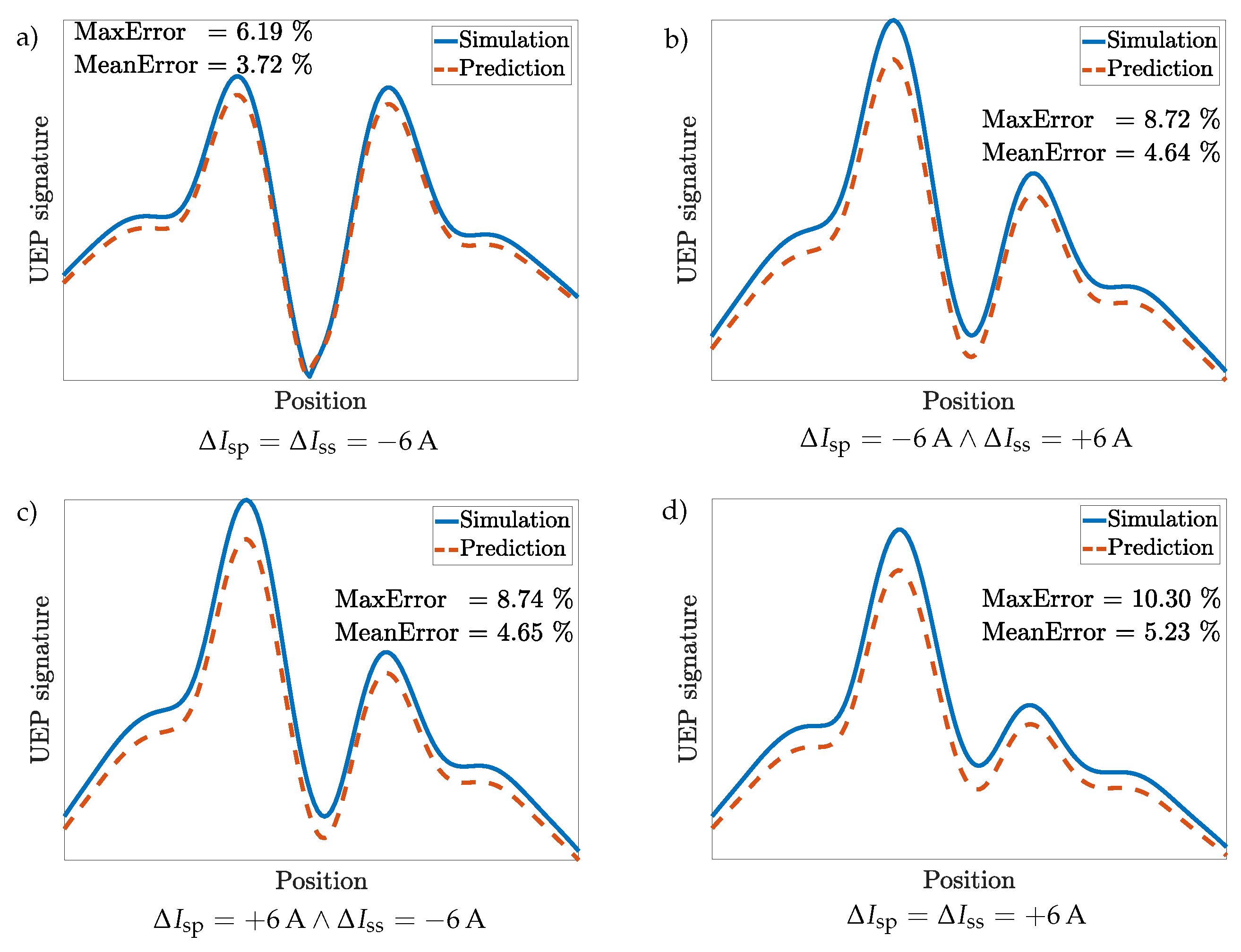
For the first scenario the ship’s hull as well as the sea chests are represented by the polarization curve of HY-80 steel (Figure 3b) with a coating damage of 5% for the hull and 1% for the sea chests. The propellers are considered to be uncoated. To evaluate the prediction accuracy of the aforementioned prediction Formulae (8)–(10), the calculated UEP signature is compared to a simulated scenario, where all ICCP electrodes are simultaneously active with new impressed ICCP currents. In the UEP prediction examples presented in Figure 6 the impressed currents of the bow electrodes are kept constant at the reference ICCP current of 35 A and the stern electrodes are altered as changes of the ICCP currents close to the propeller have a more significant influence on the total UEP signature changes, due to the nonlinear effect of the corrosion process, which is more dominant near the propellers. For the examples shown, the impressed currents have been altered relatively to the reference scenario ICCP current at each ICCP electrode, which can be described as
Δ I i = I i , ref + I i ,
with I i , ref representing the reference ICCP current and I i the new impressed current for the specific ICCP electrode i. Hence, negative changes of Δ I i describe a decrease of the impressed current and a positive value represents an increase of the impressed current at each electrode, respectively. For the estimation of the prediction accuracy the deviation of the predicted UEP signature and the simulated UEP signature have been calculated using the expression
Deviation = UEP sim , tot UEP pred , tot max UEP sim , tot · 100 % .
Furthermore, the maximum deviation and the mean deviation of both simulated and predicted UEP signatures have been calculated and with a maximum error of approximately 10% (cf. Figure 6d) the prediction accuracy of the superposition formulation is sufficient.
The deviation between the predicted UEP signature and the simulated UEP signature can be explained with the changes of the UEP signature generated by the corrosion process, which will alter for different ICCP current configurations due to the changes of the operating points within the nonlinear polarization curves. As an approximation for the UEP signature prediction formulation this alteration of the UEP signature generated by the corrosion process is considered to be unchanged with respect to the adjustments of the ICCP currents as changes of the corrosive UEP signature are expected to be small compared to the changes of the UEP signature generated by the ICCP system.

3.4. Scenario 2: Bare Steel Hull

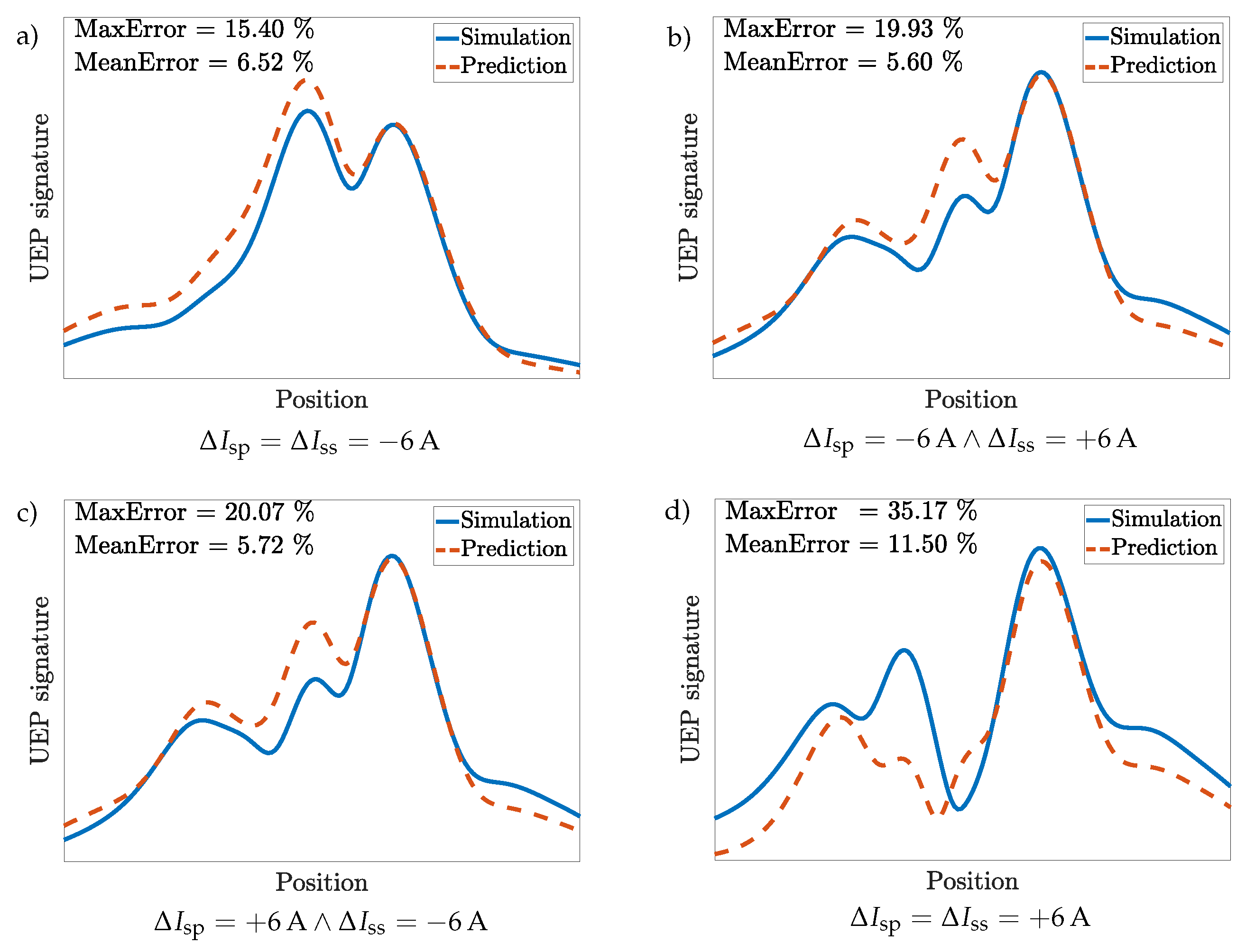
In the second scenario the polarization curve of bare steel is chosen for the hull and the sea chests and the coating conditions of the ship model are kept the same like presented in scenario 1. The UEP signature prediction deviates more significantly compared to scenario 1 (cf. Figure 6) as can be seen in Figure 7. Especially the left part of each UEP signature, which corresponds to the aft ship the prediction accuracy is lower, which can be explained with the stronger presence of the highly nonlinear corrosion process dominating in close vicinity to to the propellers and thus, the prediction accuracy is aggravated. Furthermore, in the shown case stronger ICCP currents result in higher variations of the predicted UEP signature compared to the simulated UEP signature and is an indication for more concise changes in the operating points in the polarization curves. Even though the maximum of the UEP signature is predicted well (except for Figure 7a) a deviation greater than 15% between predicted and simulated UEP signature has to be considered as insufficient and elucidates the strong influence of the corrosion process for the chosen material combinations, which have to be evaluated individually. Hence, no general rule to superimpose single UEP signatures for all material combinations is possible.

3.5. Scenario 3: Bare Steel with Coated Propellers

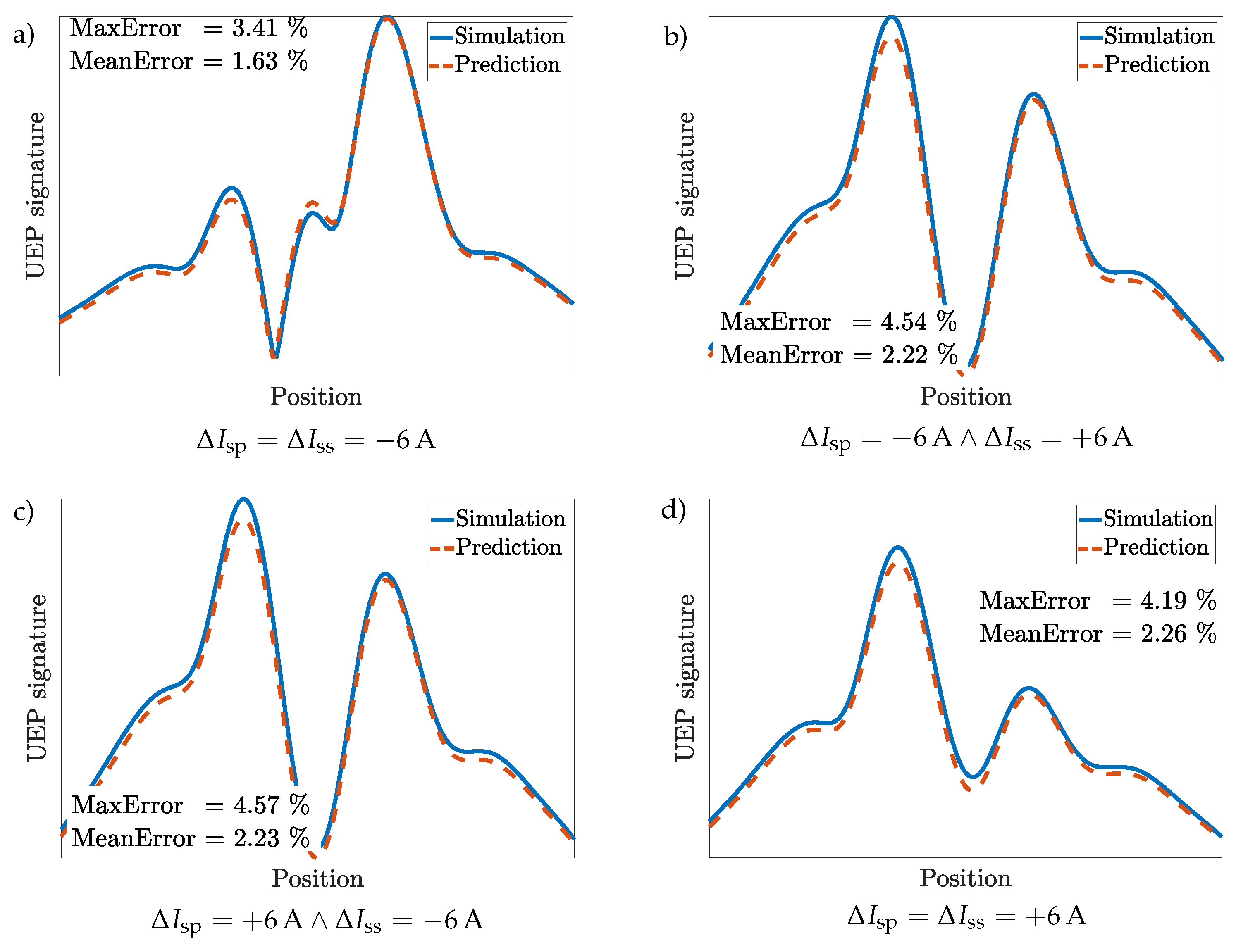
To enhance the prediction accuracy for the material combination presented for the bare steel scenario in Section 3.4 a coating of the propellers is introduced to lower the influence of the nonlinear corrosion process on the total UEP signature. Usually, this propeller coating is applied on real ships to reduce the overall UEP signature due to lower ICCP currents, which are needed to satisfy the corrosion protection condition of the vessel. Thus, the UEP signature generated by the ICCP system is simultaneously reduced. In the following prediction example shown in Figure 8 the reference ICCP currents have been adjusted to just match the corrosion protection condition when a coating of the propellers similar to the hull/sea chests is introduced.
Here, a coating damage of the propellers of 10% is applied to each propeller and it can be seen, that the prediction accuracy is improved significantly to a maximum deviation of approximately 4.5% for the presented case. Here, the generated UEP signature is mainly generated by the ICCP system and the nonlinear corrosion UEP signature is virtually inhibited by the coating of the propeller when compared to the dominating UEP signature generated by the ICCP electrodes. Therefore, the nonlinear behavior of the UEP signature due to the corrosion process should be investigated in case of a real ship (if possible). If the influence of the corrosion process on the total UEP signature is comparably weak, the presented superposition formulation can be utilized to accurately predict the total UEP signature for changes in the ICCP currents. Here, single reference UEP signatures of each ICCP electrode and the corresponding ICCP currents for corrosion protection are needed, which both can be accessed either by the onboard monitoring system to extract the present ICCP currents or by measuring the UEP signature at a corresponding measurement site.

4. Conclusions

In this work, a linear superposition formulation to predict the UEP signature of naval vessels—even though nonlinear corrosion processes are involved—is presented using only a reference UEP signature and the corresponding ICCP currents (and namely their changes) for corrosion protection of the vessel. When applying the HY-80 steel polarization curve for the hull and sea chests including a coating damage of 5% for the hull and 10% for the sea chests a maximum deviation of 10% between the simulated UEP signature and the predicted UEP signature was achieved, which can be considered as an accurate prediction result. When changing the material from the HY-80 steel to bare steel for the hull as well as the sea chests the prediction accuracy decreases to a maximum deviation of 35% representing an insufficient UEP signature prediction, even though the maximum value of the UEP signature is predicted well. The higher prediction deviation corresponds to the highly nonlinear corrosion process, which is more concise for the material combination of bare steel and NAB. This result clarifies the strong influence of the corrosion process to the total UEP signature yielding an insufficient prediction accuracy for UEP signatures if the influence of the corrosion process is significant. Therefore, not all material combinations allow a sufficient UEP signature prediction and the UEP signature behavior for different ICCP current configurations has to be investigated to successfully superimpose single UEP signatures generated by each ICCP electrode to predict the total UEP signature of the naval vessel. With an applied propeller coating, which weakens the nonlinear corrosion process the prediction accuracy could be significantly improved due to the now dominating UEP signature generated by the ICCP system. With a coating damage of 10% for both propellers the deviation between the predicted UEP signature and the simulated UEP signature could be minimized to be below 5% for the material combination of bare steel and NAB. Thus, accurate prediction results while simultaneously lowering the total UEP signature due to the lower demand of ICCP currents to protect the vessel from corrosion for different ICCP current configurations are provided. However, a general UEP signature prediction for every material combination is not directly achievable and the specific material behavior in terms of the corrosion process has to be evaluated to apply the superposition concept presented here. Finally, this work elucidates the critical influence of the corrosion UEP signature to the total UEP signature of naval vessels and helps to improve the understanding of the corrosion behavior for different ICCP current configuration. Furthermore, the presented prediction formulation can be utilized as a fast methodology to estimate the risk of detection of a vessel using the mere information of single reference UEP signatures generated by each ICCP electrode and the corresponding ICCP currents.

Author Contributions

C.T. conceived and designed the computational setup; C.T. and C.B. performed the simulations; C.T. and D.E. wrote the paper; F.L. gave consultancy in cathodic protection systems; J.D. gave consultancy in corrosion processes on naval vessels; A.R. supervised the findings in this work and contributed to the writing process. All authors have read and agreed to the published version of the manuscript.

Funding

This research was funded by the Technical Center for Ships and Naval Weapons, Naval Technology and Research (WTD71), Bundeswehr, grant number E/E71Z/F0697/EF025.

Conflicts of Interest

The authors declare no conflict of interest.

References

  1. Eberhart, R.; Kennedy, J. A new optimizer using particle swarm theory. In Proceedings of the 6th International Symposium on Micro Machine and Human Science, Nagoya, Japan, 4–6 October 1995; pp. 39–43. [Google Scholar]
  2. Peng, Y.; Cheng, J.; Jiang, R. Inversion of UEP signatures induced by ships based on PSO method. Def. Technol. 2019. [Google Scholar] [CrossRef]
  3. Schaefer, D.; Doose, J.; Pichlmaier, M.; Rennings, A.; Erni, D. Conversion of UEP signatures between different environmental conditions using shaft currents. IEEE J. Ocean. Eng. 2016, 41, 105–111. [Google Scholar]
  4. Schaefer, D. Vorhersage und Umrechnung korrosionsbedingter UEP-Signaturen von Wasserfahrzeugen. Ph.D. Thesis, University of Duisburg-Essen, Duisburg, Germany, 2015. [Google Scholar]
  5. Schaefer, D.; Thiel, C.; Doose, J.; Rennings, A.; Erni, D. Above water electric potential signatures of submerged naval vessels. J. Mar. Sci. Eng. 2019, 7, 53. [Google Scholar] [CrossRef] [Green Version]
  6. COMSOL Multiphysics. Finite Element Method Solver. Available online: https://www.comsol.de/ (accessed on 17 January 2020).
  7. Hack, H. Atlas of Polarization Diagrams for Naval Materials in Seawater; Technical report; Naval Surface Warfare Center: Bethesda, MD, USA, 1995. [Google Scholar]
  8. Carson, S.; Orazem, M. Time-dependent polarization behaviour of pipeline grade steel in low ionic strength environments. J. Appl. Electrochem. 1999, 29, 703–717. [Google Scholar] [CrossRef]
  9. Blackburn, J.M. Base Materials for Critical Applications: Requirements for lo Alloy Steel Plate, Forgings, Castings, Shapes, Bars, and Heads of HY-80/100/130 and HSLA-80/100; Techreport; NAVSEA: Washington, DC, USA, 2012. [Google Scholar]
  10. Datasheet: CuAl10Ni5Fe5-C, Deutsches Kupferinstitut; Technical report; Deutsches Kupferinstitut: Düsseldorf, Germany, 2005.
  11. Anodes, Corrosion Preventive, Zinc; Slab, Disc and Rod Shaped, Military Specification, MIL-A-18001J; Technical report; Military Specification, Naval Sea Systems Command, SEA 55Z3; Department of the Navy: Washington, DC, USA, 1983.
  12. Huber, T.; Wang, Y. Effect of propeller coating on cathodic protection current demand: Sea trial and modeling studies. CORROSION 2012, 68, 441–448. [Google Scholar] [CrossRef]
  13. Kathodischer Korrosionsschutz von Schiffen—Außenschutz durch Fremdstrom —VG 81 259 Teil 1–3; Technical report; Deutsches Institut für Normung (DIN): Berlin, Germany, 1994.
Figure 1. Bottom view of the generic ship model installed with a four-zone impressed current cathodic protection (ICCP) system (red circular patches) and an additional sacrificial anode cathodic protection (SACP) system (blue circular patches) at the stern region and inside the sea chests (not visible here) to smooth the electric potential distribution of the hull for corrosion protection. Furthermore, the propellers are approximated as discs.
Jmse 08 00105 g001
Figure 2. Numerical setup including water domain and seabed domain within COMSOL Multiphysics to calculate the underwater electric potential (UEP) signature of the generic ship model. For extracting the electric signature of the vessel a UEP signature line is positioned midship 20 m below the keel. Additionally, all boundaries except the top layer are surrounded by infinite elements to account for a virtually infinite region.
Jmse 08 00105 g002
Figure 3. Polarization curves defined as electric potential φ over electric current density J for the subfiguresv (ad) are used as boundary conditions for the numerical ship model in COMSOL. The polarization curve can be separated into the cathodic branch and the anodic branch as depicted in (b), with the former representing a positive current density pointing towards the material surface and the latter representing negative current densities flowing outside the material surface. The transition between both branches defines the equilibrium state, in which the number of oxidation and reduction reactions are equal. For the stated equilibrium the current density will be zero. All polarization data were taken from [7] and were recalculated for an Ag/AgCl reference electrode when the reference electrode differed from the Ag/AgCl electrode. To account for a perforated coating a correspondingly weighted current density of the polarization curve is applied as can be seen in (a). As an example, 10% shall represent a hull coating with a homogeneous damage of 10%.
Jmse 08 00105 g003
Figure 4. Simulated electric potential distribution as a reference scenario for corrosion protection of the generic ship model. In the shown case, the ICCP currents of the bow electrodes are set to 9 A and the ICCP currents of the stern electrodes are set to 15 A to match the desired corrosion protection condition for bare steel. Note that the presented example neither includes optimized ICCP electrode positions, nor an optimized SACP system.
Jmse 08 00105 g004
Figure 5. Schematic prediction principle for a four-zone ICCP system. For each electrode the UEP signature for corrosion protection is extracted and superimposed to achieve the reference UEP signature UEPref. The present UEP signature is than calculated by utilizing the ICCP current changes at each ICCP electrode δ I i as a linear scaling factor. For weak corrosion processes the UEP signature changes can be solely described by the changes of the ICCP system.
Jmse 08 00105 g005
Figure 6. Scenario 1 (Hy-80 steel hull): prediction example of the magnitude of the UEP signature for changing the impressed currents (subfigure (ad)) of the ICCP electrodes at the stern using the prediction formulae from the Equations (8)–(10) and the polarization curve of the HY-80 steel for the hull and sea chests. The difference of the impressed current of the portside electrode Δ I sp and the starboard electrode Δ I ss represent the adjustment of the ICCP currents in correspondence to the reference ICCP currents at said electrode for corrosion protection. With a maximum deviation of approximately 10% in (d) the prediction accuracy can be defined as sufficient.
Jmse 08 00105 g006
Figure 7. Scenario 2 (bare steel hull): Prediction example of the magnitudes of the UEP signature for changing the impressed currents (subfigure (ad)) of the ICCP electrodes at the stern using the prediction formulae of the Equations (8)–(10) and the polarization curve of bare steel for the hull and sea chests. Here, compared to the prediction accuracy for the HY-80 steel in Figure 6 higher deviations for the predicted UEP signatures are present, which can be explained by the stronger influence of the UEP signature generated by the nonlinear corrosion process on the total UEP signature.
Jmse 08 00105 g007
Figure 8. Scenario 3 (bare steel hull with coated propellers): Prediction example of the magnitudes of the UEP signature for changing the impressed currents (subfigure (ad)) of the ICCP electrodes at the stern using the prediction formulae of the Equations (8)–(10) and the polarization curve of bare steel for the hull and sea chests including coated propellers with a defined coating damage of 10% for each propeller. Implementing a coating to the propellers lowers the influence of the nonlinear corrosion process to the total UEP signature and significantly improves the prediction accuracy to a maximum deviation of approximately 4.5%.
Jmse 08 00105 g008