Interaction Effect between Hull and Accommodation on Wind Drag Acting on a Container Ship


Abstract

1. Introduction
2. Original Model and Computed Domain
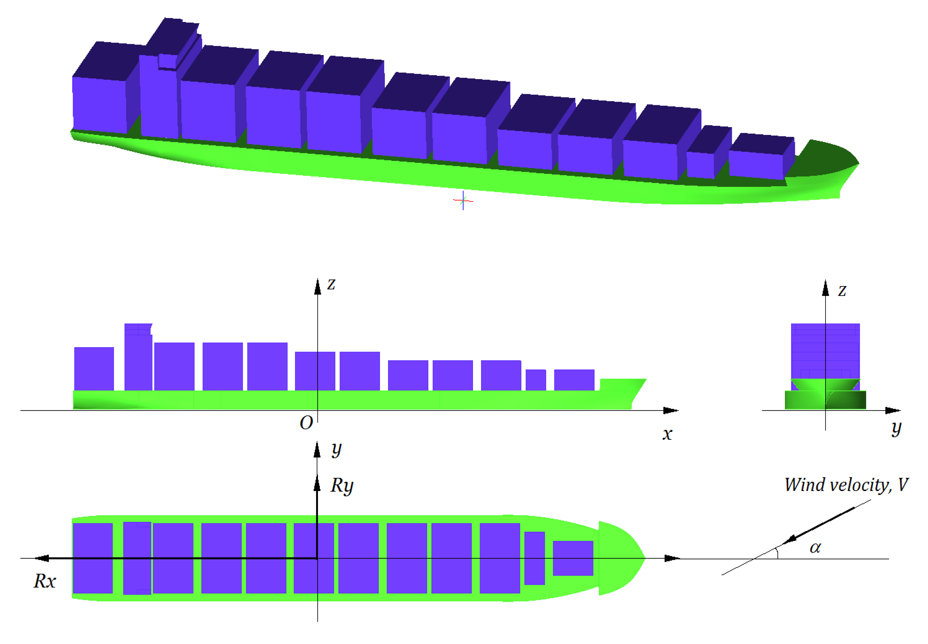
2.1. Model Ship Used for Computation
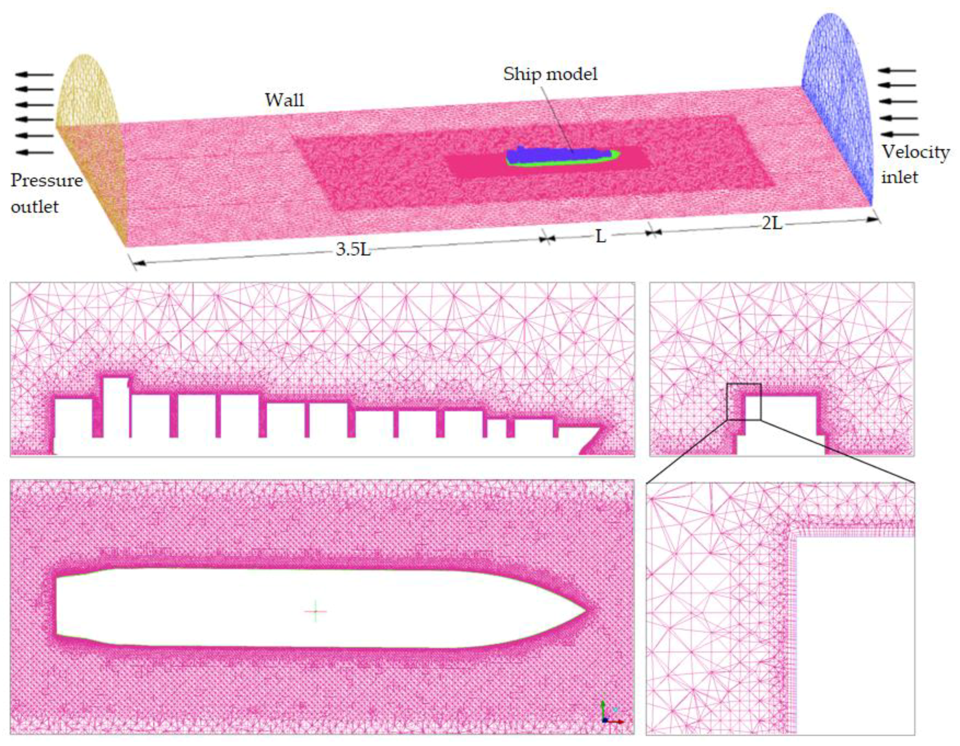
2.2. Computational Domain and Boundary Conditions
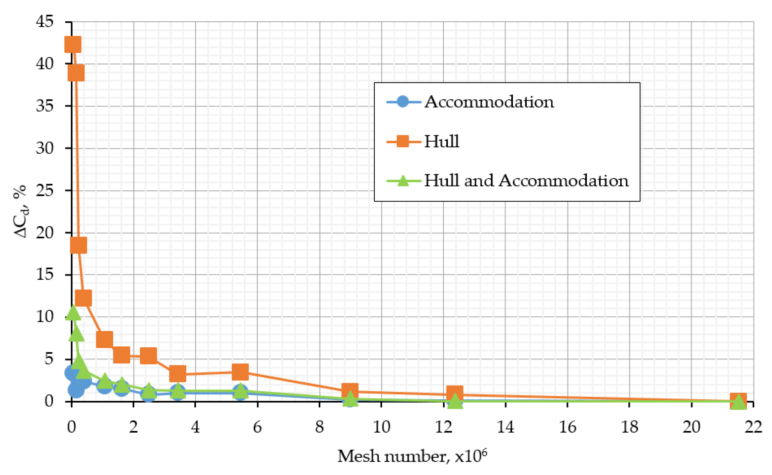
2.3. Covegence of Mesh Using for Computation
- Cd is the wind drag coefficient.
- Rx is the wind drag acting on the hull, N.
- AF(x) is the frontal projected area, m2.
- V is the ship velocity, m/s.
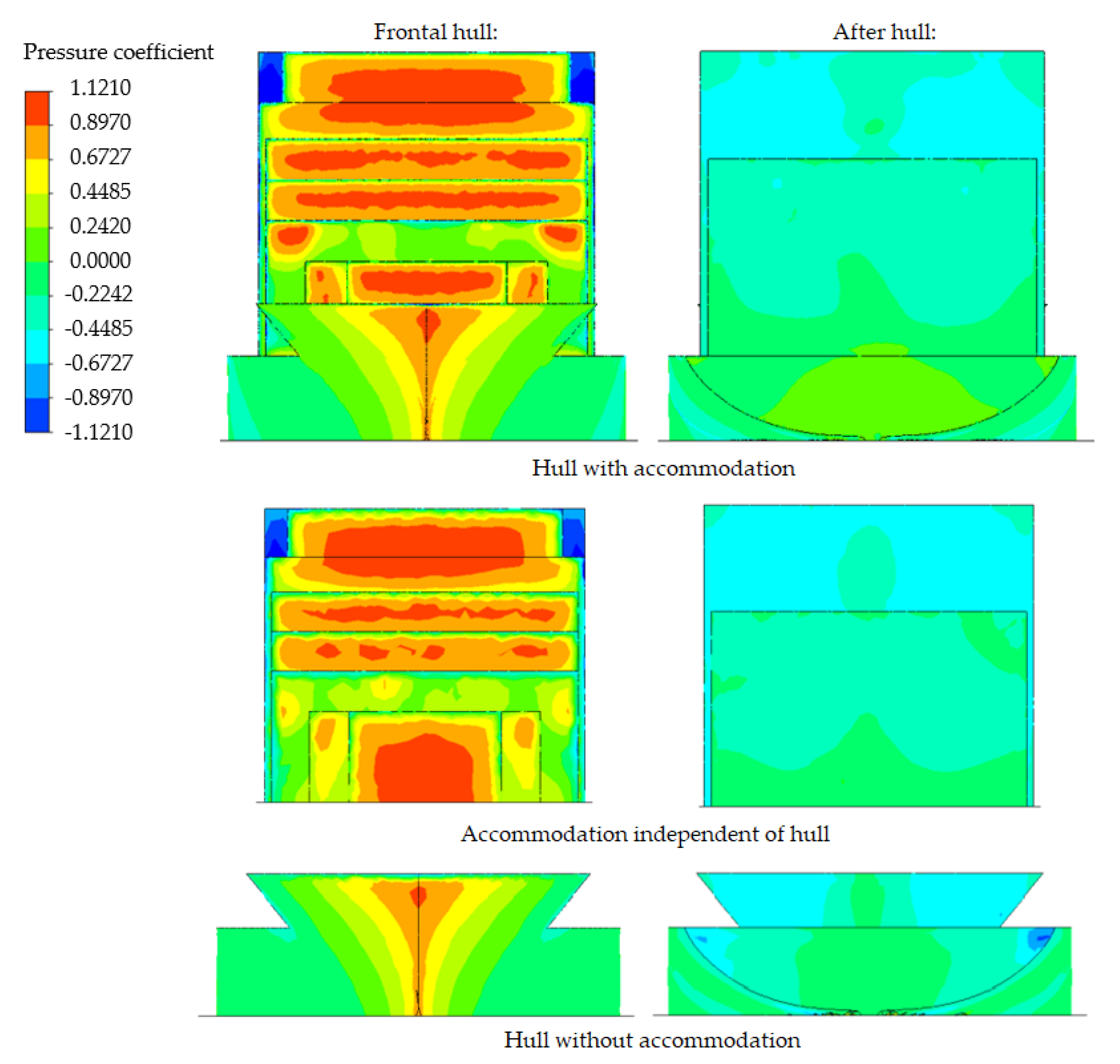
3. Interaction Effect between Hull and Accommodation
- ΔCd, % is the interaction effect between hull and accommodation.
- Cd (Hull with Acc) is wind drag coefficient acting on the hull with accommodation.
- Cd (Independent Hull and Acc) is total wind drag coefficient acting on hull without accommodation and independent accommodation.
4. Reduced Interaction Effect on Wind Drag Acting on the Container Ship
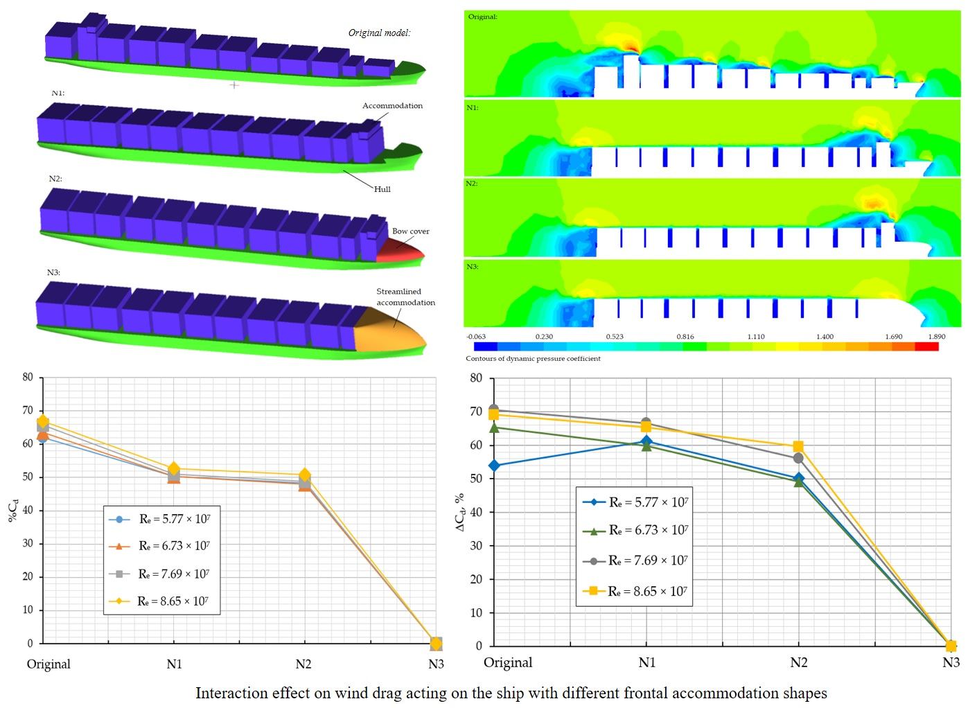
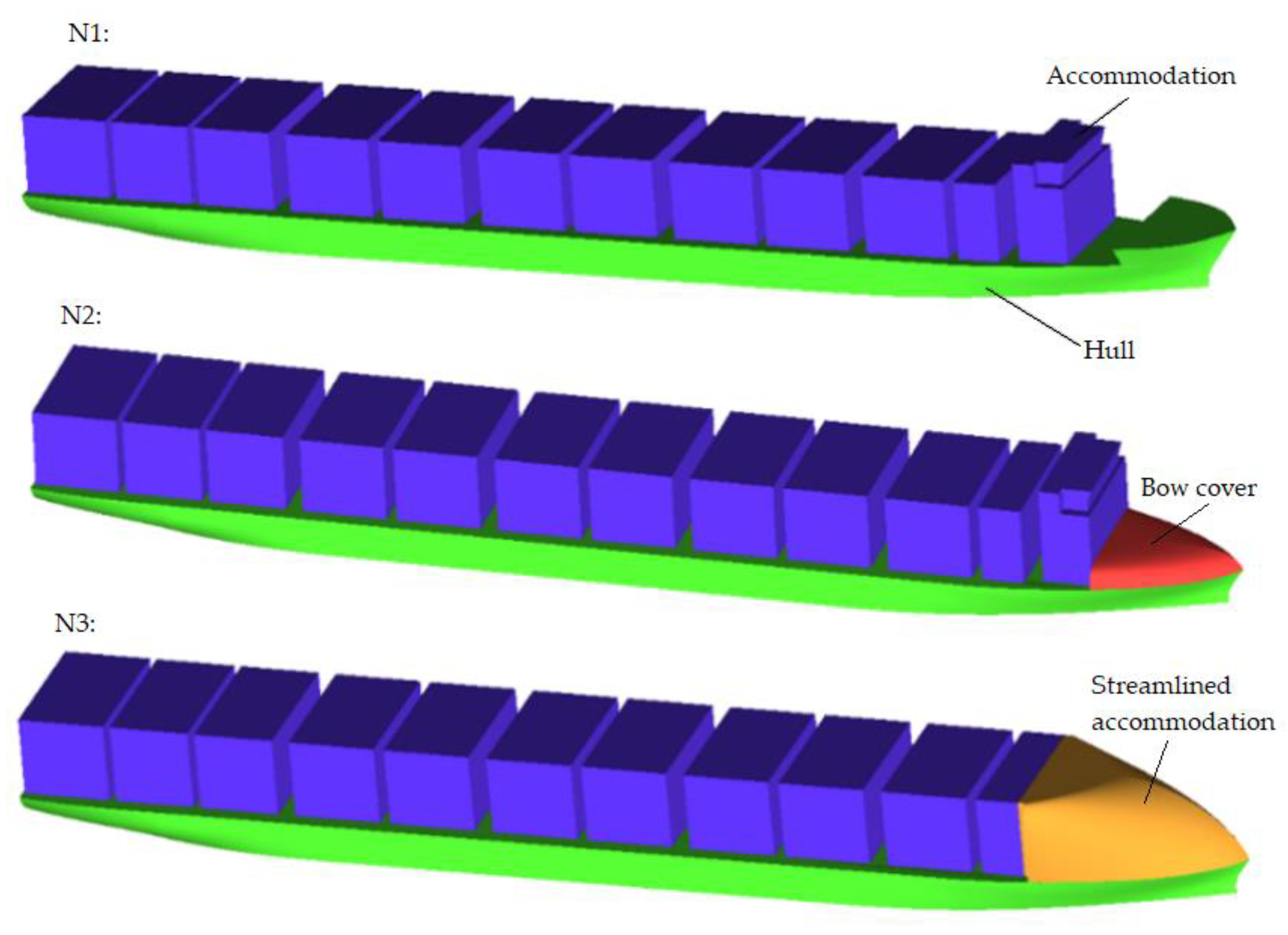
4.1. Proposed Accommodation Shape for the Ship
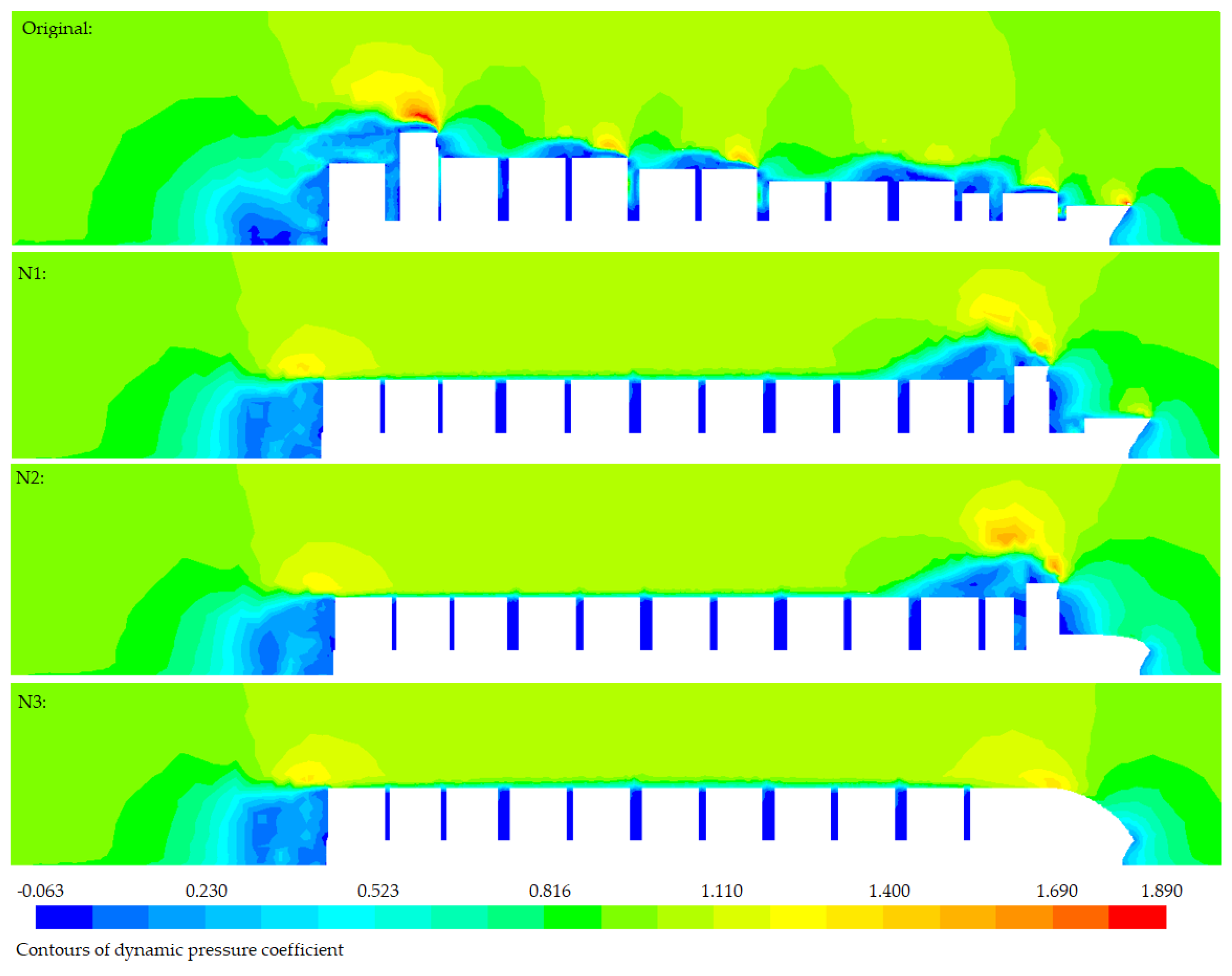
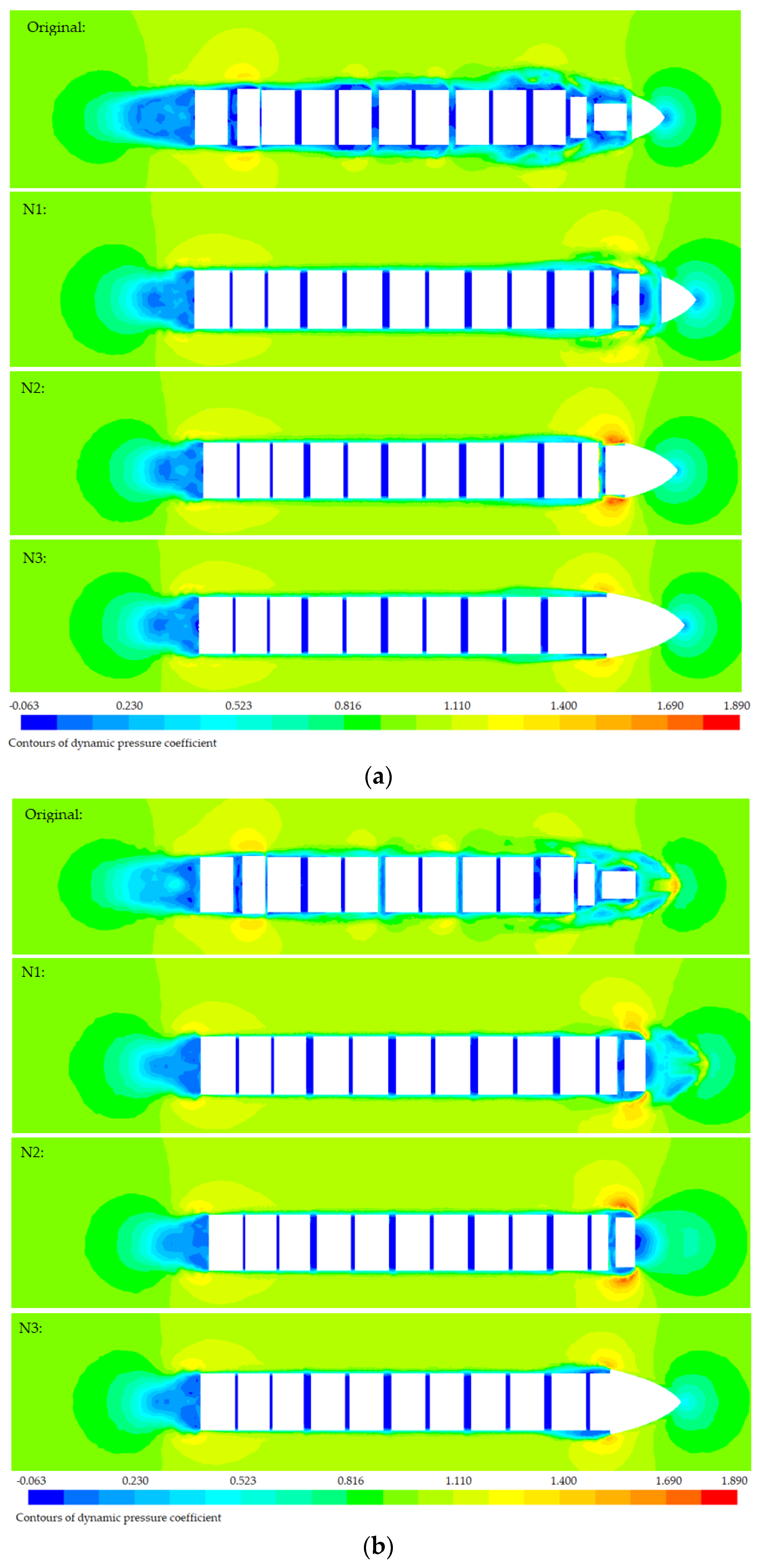
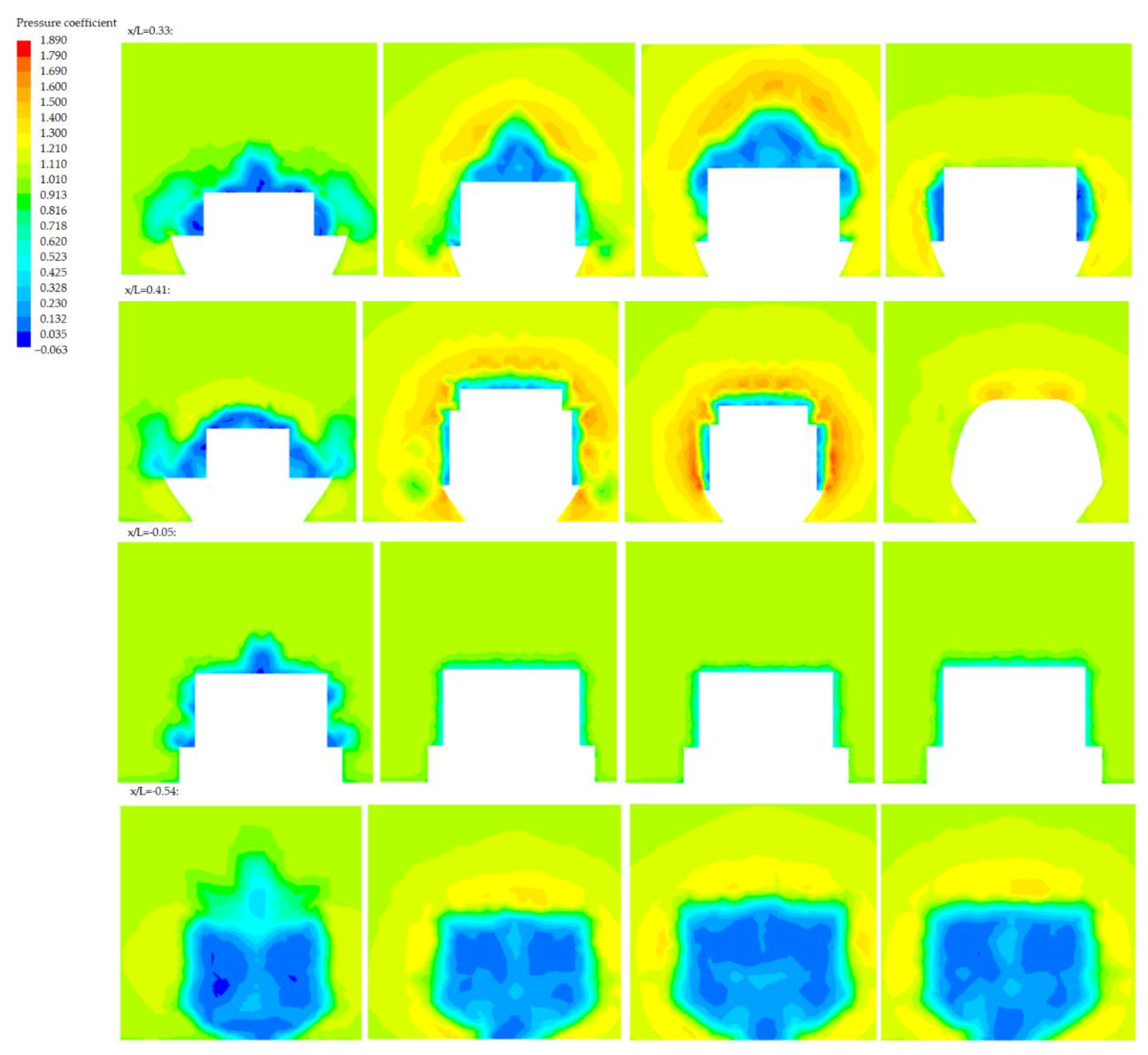
4.2. Reduced Interaction Effect of the New Hull Shapes on Pressure Distribution
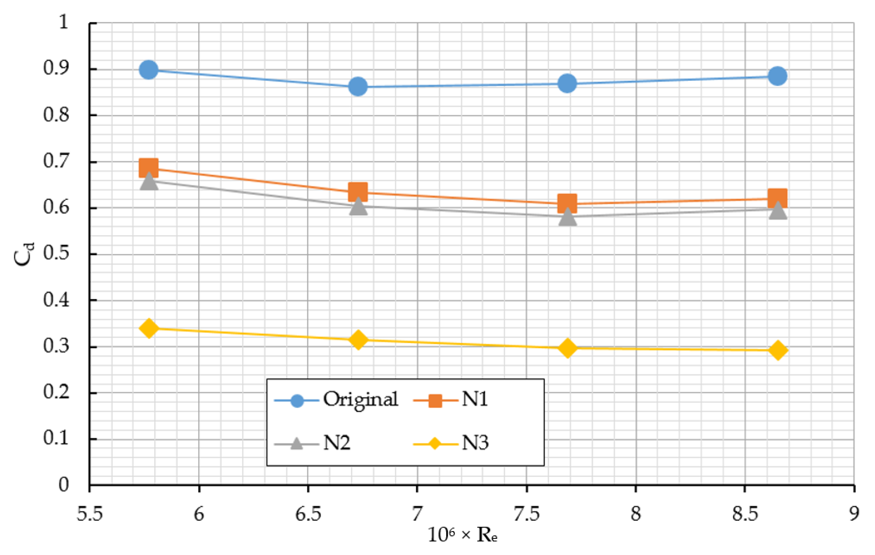
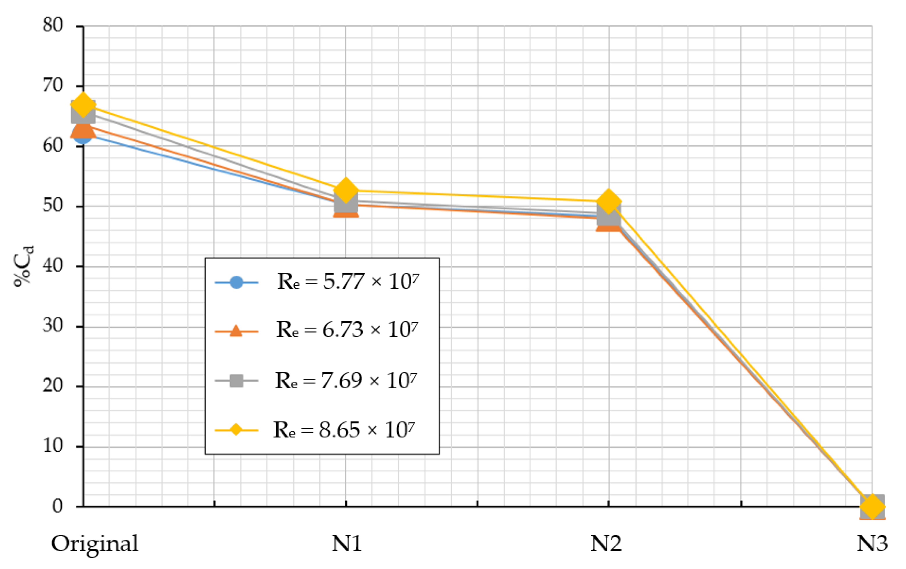
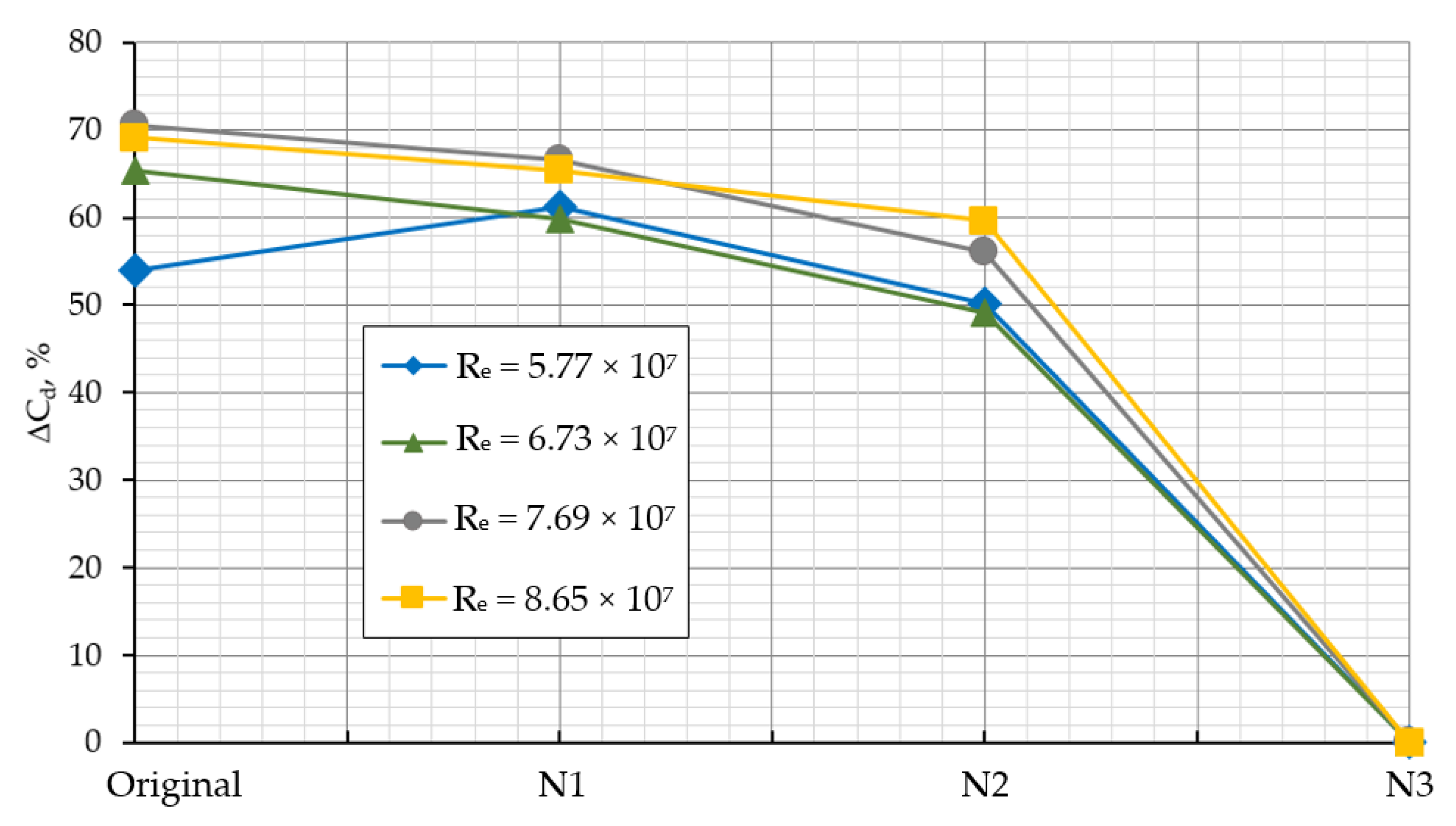
4.3. Interaction Effect between Hull and Accommodation on Wind Drag
5. Conclusions
- The effect of mesh number on aerodynamic performances of the reference container ship has been determined. The obtained results show that the effect of mesh number on wind drag acting on the container ship is about 10% when the value of y+ is less than 50 and the same value when y+ is less than 7.
- The CFD results for the two computed cases, namely the original ship hull with and without accommodation, have been obtained. The effect of the hull on the wind drag is as high as 42%, while the interaction effect between hull and accommodation of the container ship on the total wind drag has been evaluated and is only about 10%.
- The newly proposed frontal accommodation shapes’ effect on aerodynamic performance as well as wind drag acting on hull of the ship. It has been shown that the developed frontal accommodation shapes affect both the pressure distribution around the ship hull and the separation regions around the accommodation. Hence, a suitable shape of the frontal accommodation could be installed to greatly reduce the total wind drag.
- The effect of accommodation shapes on wind drag acting on hull of the ship has been investigated. Using the proposed frontal accommodation shapes, up to 30% of the total wind drag in head wind (N1), and up to 66.88% of the total wind drag acting on the hull at a Reynolds number of 8.65 × 10⁷ in head wind (N3), could be reduced.
- The interaction effect between the hull and accommodation of the ship, with different accommodation shapes, has been investigated. Drastically reduced interaction effects on wind drag acting on the hull, using the accommodation shape N2 (up to 49%) and using the accommodation shape N3 (up to 70%), have been shown.
Author Contributions
Funding
Acknowledgments
Conflicts of Interest
References
- Janssen, W.; Blocken, B.; van Wijhe, H. CFD simulations of wind loads on a container ship: Validation and impact of geometrical simplifications. J. Wind Eng. Ind. Aerodyn. 2017, 166, 106–116. [Google Scholar] [CrossRef]
- Andersen, I.M.V. Wind loads on post-panamax container ship. Ocean Eng. 2013, 58, 115–134. [Google Scholar] [CrossRef]
- Fujiwara, T.; Tsukada, Y.; Kitamura, F.; Sawada, H. Experimental Investigation and Estimation on Wind Forces for a Container Ship. In Proceedings of the Nineteenth International Offshore and Polar Engineering Conference, Osaka, Japan, 21–26 July 2009; pp. 555–562. [Google Scholar]
- Kim, Y.; Kim, K.-S.; Jeong, S.-W.; Jeong, S.-G.; Van, S.-H.; Kim, Y.-C.; Kim, J. Design and performance evaluation of superstructure modification for air drag reduction of a container ship. In Proceedings of the Twenty-Fifth International Ocean and Polar Engineering Conference, Kona, HI, USA, 21–26 June 2015. [Google Scholar]
- Van Nguyen, T.; Kinugawa, A. Development of Practical Gap Covers to Reduce Air Resistance Acting on Deck Containers of a Ship. In Proceedings of the 23th conference Japan Society of Naval Architects and Ocean Engineers, Hiroshima, Japan, 2017; pp. 211–216. [Google Scholar]
- Van Nguyen, T. Vortex Control in Gap Flow by Small Appendages to Reduce Air Resistance Acting on Deck Containers of a Ship. In Proceedings of the 24th Conference Japan Society of Naval Architects and Ocean Engineers, Tokyo, Japan, 26 May 2017; pp. 335–338. [Google Scholar]
- Watanabe, I.; Van Nguyen, T.; Miyake, S.; Shimizu, N.; Ikeda, Y. A study on reduction of air resistance acting on a large container ship. Proc. APHydro 2016, 2016, 321–330. [Google Scholar]
- Seok, J.; Park, J.-C. Comparative Study of Air Resistance with and without a Superstructure on a Container Ship Using Numerical Simulation. J. Mar. Sci. Eng. 2020, 8, 267. [Google Scholar] [CrossRef]
- Wnęk, A.; Soares, C.G. Numerical Analysis of the Shadow Effect of an LNG Floating Platform on an LNG Carrier under Wind Conditions. In Sustainable Maritime Transportation and Exploitation of Sea Resources; Taylor & Francis Group: London, UK, 2012. [Google Scholar]
- Wnęk, A.; Soares, C.G. CFD assessment of the wind loads on an LNG carrier and floating platform models. Ocean Eng. 2015, 97, 30–36. [Google Scholar] [CrossRef]
- Saydam, A.Z.; Taylan, M. Evaluation of wind loads on ships by CFD analysis. Ocean Eng. 2018, 158, 54–63. [Google Scholar] [CrossRef]
- He, N.V.; Ikeda, Y. A Study on Interaction Effects between Hull and Accommodation on air Resistance of a Ship. In Proceedings of the Conference Japan Society of Naval Architects and Ocean Engineers, Fukuoka, Japan, 27–28 May 2013; pp. 281–284. [Google Scholar]
- Van He, N.; Mizutani, K.; Ikeda, Y. Reducing air resistance acting on a ship by using interaction effects between the hull and accommodation. Ocean Eng. 2016, 111, 414–423. [Google Scholar] [CrossRef]
- Van He, N.; Mizutani, K.; Ikeda, Y. Effects of side guards on aerodynamic performances of the wood chip carrier. Ocean Eng. 2019, 187, 106217. [Google Scholar] [CrossRef]
- Sugata, K.; Iwamoto, Y.; Ikeda, Y.; Nihei, Y. Reduction of Wind Force Acting on Non Ballast Ship. In Proceedings of the 5th Asia Pacific Workshop on Marine Hydrodynamics-APHydro2010, Osaka, Japan, 1–4 July 2010; pp. 1–4. [Google Scholar]
- Du, L.; Lin, Z.; Jiang, Y.; Li, P.; Dong, Y. Numerical Investigation on the Scale Effect of a Stepped Planing Hull. J. Mar. Sci. Eng. 2019, 7, 392. [Google Scholar] [CrossRef]
- Schmitt, P.; Windt, C.; Davidson, J.; Ringwood, J.V.; Whittaker, T. The efficient application of an impulse source wavemaker to cfd simulations. J. Mar. Sci. Eng. 2019, 7, 71. [Google Scholar] [CrossRef]
- Zalesny, V.; Agoshkov, V.; Aps, R.; Shutyaev, V.; Zayachkovskiy, A.; Goerlandt, F.; Kujala, P. Numerical modeling of marine circulation, pollution assessment and optimal ship routes. J. Mar. Sci. Eng. 2017, 5, 27. [Google Scholar] [CrossRef]
- Feng, D.; Ye, B.; Zhang, Z.; Wang, X. Numerical Simulation of the Ship Resistance of KCS in Different Water Depths for Model-Scale and Full-Scale. J. Mar. Sci. Eng. 2020, 8, 745. [Google Scholar] [CrossRef]
- Viola, I.M. Downwind sail aerodynamics: A CFD investigation with high grid resolution. Ocean Eng. 2009, 36, 974–984. [Google Scholar] [CrossRef]
- Nguyen, T.; Shimizu, N.; Kinugawa, A.; Tai, Y.; Ikeda, Y. Numerical studies on air resistance reduction methods for a large container ship with fully loaded deck-containers in oblique winds. In Proceedings of the VII International Conference on Computational Methods in Marine Engineering, MARINE, Gothenburg, Sweden, 13–15 May 2019; pp. 1040–1051. [Google Scholar]
- Ittc, R. Procedures and Guidelines: Practical Guidelines for Ship CFD Applications, 7.5; ITTC: London, ON, Canada, 2011; pp. 1–18. [Google Scholar]
- Celik, I.B.; Ghia, U.; Roache, P.J.; Freitas, C.J. Procedure for estimation and reporting of uncertainty due to discretization in CFD applications. J. Fluids Eng. Trans. Asme 2008, 1–130. [Google Scholar]
- Collie, S.; Gerritsen, M.; Jackson, P. A Review of Turbulence Modeling for Use in Sail Flow Analysis; Report; University of Auckland’s Faculty of Engineering: Auckland, New Zealand, 2001. [Google Scholar]
- Xia, M.; Jiang, L. Application of an unstructured grid-based water quality model to Chesapeake Bay and its adjacent coastal ocean. J. Mar. Sci. Eng. 2016, 4, 52. [Google Scholar] [CrossRef]
- Windt, C.; Davidson, J.; Schmitt, P.; Ringwood, J.V. On the assessment of numerical wave makers in CFD simulations. J. Mar. Sci. Eng. 2019, 7, 47. [Google Scholar] [CrossRef]
- Bertram, V. Practical Ship Hydrodynamics; Elsevier: Amsterdam, The Netherlands, 2011. [Google Scholar]
- Murdock, J.W. Fundamental Fluid Mechanics for the Practicing Engineer; CRC Press: Boca Raton, FL, USA, 1993. [Google Scholar]


| Name | Description | Value | Unit |
|---|---|---|---|
| L | Length | 176.20 | m |
| B | Breadth | 24.90 | m |
| H | Depth | 13.70 | m |
| d | Draft | 8.30 | m |
| AF(x) | Frontal projected area | 541.29 | m2 |
| AF(y) | Lateral projected area | 2483.23 | m2 |
| Cb | Block coefficient | 0.68 | - |
| α | Wind attack angle | 0 | degree |
| V | Wind velocity | 12–18 | knot |
| Re | Reynolds number | (5.8–8.7) × 107 | - |
| No. | y+ | Total Elements (×106) | Minimum Face Area, m2 (×10−2) | Maximum Face Area, m2 (×102) | Minimum Volume, m3 (×10−3) | Maximum Volume, m3 (×103) |
|---|---|---|---|---|---|---|
| 1 | 502.49 | 0.0575 | 64.3907 | 3.1801 | 414.689 | 1.3602 |
| 2 | 358.92 | 0.1504 | 29.3068 | 2.3441 | 117.371 | 0.9033 |
| 3 | 215.35 | 0.2267 | 2.3832 | 2.0662 | 6.66706 | 0.8561 |
| 4 | 143.57 | 0.3881 | 2.9348 | 4.6849 | 4.32068 | 2.8079 |
| 5 | 71.78 | 1.0761 | 0.2197 | 3.6252 | 0.08926 | 1.8030 |
| 6 | 50.25 | 1.6178 | 0.5163 | 2.6564 | 0.49978 | 0.9891 |
| 7 | 35.89 | 2.4881 | 0.9272 | 3.0937 | 0.99869 | 2.1242 |
| 8 | 21.54 | 3.4288 | 1.1114 | 1.4511 | 0.81512 | 0.6278 |
| 9 | 14.36 | 5.4566 | 0.0548 | 4.8017 | 0.01296 | 2.7449 |
| 10 | 7.18 | 8.9854 | 0.0121 | 1.0236 | 0.00326 | 0.6128 |
| 11 | 3.59 | 12.3683 | 0.0092 | 1.2763 | 0.00163 | 0.7629 |
| 12 | 1.08 | 21.5228 | 0.0016 | 2.0125 | 0.00032 | 0.6293 |
| Total Elements (×106) | Wind Drag, Rx (N) | Wind Drag Coefficient, Cd | ||||
|---|---|---|---|---|---|---|
| Acc | Hull | Total | Acc | Hull | Total | |
| 0.0575 | 13,464.3 | 3081.8 | 16,546.1 | 0.7829 | 0.1792 | 0.9621 |
| 0.1504 | 13,181.5 | 2910.2 | 16,091.7 | 0.7665 | 0.1692 | 0.9357 |
| 0.2267 | 13,350.4 | 2180.2 | 15,530.6 | 0.7763 | 0.1268 | 0.9031 |
| 0.3881 | 13,328.6 | 2025.4 | 15,353.9 | 0.7750 | 0.1178 | 0.8928 |
| 1.0761 | 13,245.9 | 1917.1 | 15,163.0 | 0.7702 | 0.1115 | 0.8817 |
| 1.6178 | 13,210.3 | 1880.2 | 15,090.5 | 0.7682 | 0.1093 | 0.8775 |
| 2.4881 | 13,115.6 | 1878.3 | 14,993.9 | 0.7627 | 0.1092 | 0.8719 |
| 3.4288 | 13,144.7 | 1837.1 | 14,981.7 | 0.7644 | 0.1068 | 0.8712 |
| 5.4566 | 13,142.3 | 1842.1 | 14,984.4 | 0.7642 | 0.1071 | 0.8713 |
| 8.9854 | 13,040.1 | 1798.4 | 14,838.5 | 0.7583 | 0.1046 | 0.8628 |
| 12.3683 | 13,001.2 | 1792.8 | 14,794.0 | 0.7560 | 0.1043 | 0.8603 |
| 21.5228 | 13,012.0 | 1778.1 | 14,790.1 | 0.7566 | 0.1034 | 0.8600 |
| Total Elements (×106) | Different of Wind Drag, ΔRx, % | Different of Wind Drag Coefficient, ΔCd, % | ||||
|---|---|---|---|---|---|---|
| Acc | Hull | Total | Acc | Hull | Total | |
| 0.0575 | 3.36 | 42.30 | 10.61 | 3.36 | 42.30 | 10.61 |
| 0.1504 | 1.29 | 38.90 | 8.09 | 1.29 | 38.90 | 8.09 |
| 0.2267 | 2.53 | 18.44 | 4.77 | 2.53 | 18.44 | 4.77 |
| 0.3881 | 2.37 | 12.21 | 3.67 | 2.37 | 12.21 | 3.67 |
| 1.0761 | 1.77 | 7.25 | 2.46 | 1.77 | 7.25 | 2.46 |
| 1.6178 | 1.50 | 5.43 | 1.99 | 1.50 | 5.43 | 1.99 |
| 2.4881 | 0.79 | 5.34 | 1.36 | 0.79 | 5.34 | 1.36 |
| 3.4288 | 1.01 | 3.21 | 1.28 | 1.01 | 3.21 | 1.28 |
| 5.4566 | 0.99 | 3.48 | 1.30 | 0.99 | 3.48 | 1.30 |
| 8.9854 | 0.22 | 1.13 | 0.33 | 0.22 | 1.13 | 0.33 |
| 12.3683 | 0.08 | 0.82 | 0.03 | 0.08 | 0.82 | 0.03 |
| 21.5228 | 0.00 | 0.00 | 0.00 | 0.00 | 0.00 | 0.00 |
| Wind Drag, Rx (N) | Wind Drag Coefficients, Cd | |||||
|---|---|---|---|---|---|---|
| Re × 107 | Acc | Hull | Total | Acc | Hull | Total |
| 5.77 | 9906.00 | 1438.69 | 11,344.69 | 0.7844 | 0.1139 | 0.8983 |
| 6.73 | 13,021.11 | 1793.28 | 14,814.39 | 0.7572 | 0.1043 | 0.8614 |
| 7.69 | 17,125.29 | 2417.25 | 19,542.54 | 0.7622 | 0.1076 | 0.8697 |
| 8.65 | 22,089.69 | 3052.63 | 25,142.32 | 0.7766 | 0.1073 | 0.8839 |
| Wind Drag, Rx (N) | Wind Drag Coefficients, Cd | |||||
|---|---|---|---|---|---|---|
| Re × 107 | Acc | Hull | Total | Acc | Hull | Total |
| 5.77 | 10,321.21 | 2329.01 | 12,650.22 | 0.8173 | 0.1844 | 1.0017 |
| 6.73 | 13,128.19 | 3100.13 | 16,228.31 | 0.7638 | 0.1804 | 0.9442 |
| 7.69 | 17,162.62 | 4012.14 | 21,174.76 | 0.7643 | 0.1787 | 0.9429 |
| 8.65 | 22,398.21 | 5051.24 | 27,449.45 | 0.7879 | 0.1777 | 0.9656 |
| Different Wind Drag, ΔRx, % | Difference, ΔCd, % | |||||
|---|---|---|---|---|---|---|
| Re × 107 | Acc | Hull | Total | Acc | Hull | Total |
| 5.77 | 4.02 | 38.23 | 10.32 | 4.02 | 38.23 | 10.32 |
| 6.73 | 0.82 | 42.15 | 8.71 | 0.87 | 42.19 | 8.77 |
| 7.69 | 0.22 | 39.75 | 7.71 | 0.28 | 39.79 | 7.76 |
| 8.65 | 1.38 | 39.57 | 8.41 | 1.44 | 39.60 | 8.46 |
| Wind Drag, Rx (N) | Wind Drag Coefficients, Cd | |||||
|---|---|---|---|---|---|---|
| Re × 107 | N1 | N2 | N3 | N1 | N2 | N3 |
| 5.77 | 8667.38 | 8326.23 | 4298.26 | 0.6863 | 0.6593 | 0.3404 |
| 6.73 | 10,881.60 | 10,387.23 | 5406.22 | 0.6328 | 0.6040 | 0.3144 |
| 7.69 | 13,678.13 | 13,093.17 | 6692.28 | 0.6087 | 0.5827 | 0.2978 |
| 8.65 | 17,611.17 | 16,966.34 | 8328.29 | 0.6191 | 0.5965 | 0.2928 |
| Different Wind Drag, Rx, % | Difference, Cd, % | |||||
|---|---|---|---|---|---|---|
| Re × 107 | N1 | N2 | N3 | N1 | N2 | N3 |
| 5.77 | 23.60 | 26.61 | 62.11 | 23.60 | 26.61 | 62.11 |
| 6.73 | 26.55 | 29.88 | 63.51 | 26.55 | 29.88 | 63.51 |
| 7.69 | 30.01 | 33.00 | 65.76 | 30.01 | 33.00 | 65.76 |
| 8.65 | 29.95 | 32.52 | 66.88 | 29.95 | 32.52 | 66.88 |
| Wind Drag, Rx (N) | Wind Drag Coefficients, Cd | |||||
|---|---|---|---|---|---|---|
| Re × 107 | Acc | Hull | Total | Acc | Hull | Total |
| Model N1: | ||||||
| 5.77 | 7524.57 | 1142.81 | 8667.38 | 0.5958 | 0.0905 | 0.6863 |
| 6.73 | 9398.81 | 1482.79 | 10,881.60 | 0.5465 | 0.0862 | 0.6328 |
| 7.69 | 12,049.96 | 1628.17 | 13,678.13 | 0.5363 | 0.0725 | 0.6087 |
| 8.65 | 15,623.23 | 1987.94 | 17,611.17 | 0.5492 | 0.0699 | 0.6191 |
| Model N2: | ||||||
| 5.77 | 6796.24 | 1529.99 | 8326.23 | 0.5382 | 0.1212 | 0.6593 |
| 6.73 | 8376.86 | 2010.37 | 10,387.23 | 0.4871 | 0.1169 | 0.6040 |
| 7.69 | 10,695.20 | 2397.97 | 13,093.17 | 0.4760 | 0.1067 | 0.5827 |
| 8.65 | 13,869.29 | 3097.05 | 16,966.34 | 0.4876 | 0.1089 | 0.5965 |
| Model N3: | ||||||
| 5.77 | 3271.08 | 1027.18 | 4298.26 | 0.2590 | 0.0813 | 0.3404 |
| 6.73 | 4083.03 | 1323.19 | 5406.22 | 0.2374 | 0.0769 | 0.3144 |
| 7.69 | 5106.26 | 1586.02 | 6692.28 | 0.2273 | 0.0706 | 0.2978 |
| 8.65 | 6575.66 | 1752.63 | 8328.29 | 0.2312 | 0.0616 | 0.2928 |
| Wind Drag, Rx (N) | Wind Drag Coefficients, Cd | |||||
|---|---|---|---|---|---|---|
| Re × 107 | Acc | Hull | Total | Acc | Hull | Total |
| Model N1: | ||||||
| 5.77 | 7162.61 | 2329.01 | 9491.62 | 0.5672 | 0.1844 | 0.7516 |
| 6.73 | 9011.22 | 3100.13 | 12,111.35 | 0.5240 | 0.1803 | 0.7043 |
| 7.69 | 10,987.28 | 4012.14 | 14,999.42 | 0.4890 | 0.1786 | 0.6675 |
| 8.65 | 14,406.12 | 5051.24 | 19,457.36 | 0.5064 | 0.1776 | 0.6840 |
| Model N2: | ||||||
| 5.77 | 7264.60 | 2109.13 | 9373.73 | 0.5752 | 0.1670 | 0.7423 |
| 6.73 | 8905.23 | 3019.18 | 11,924.41 | 0.5178 | 0.1756 | 0.6934 |
| 7.69 | 10,985.50 | 3827.16 | 14,812.66 | 0.4889 | 0.1703 | 0.6592 |
| 8.65 | 14,063.60 | 5016.12 | 19,079.72 | 0.4944 | 0.1763 | 0.6707 |
| Model N3: | ||||||
| 5.77 | 3432.35 | 2109.13 | 5541.48 | 0.2718 | 0.1670 | 0.4388 |
| 6.73 | 4220.22 | 3019.18 | 7239.40 | 0.2454 | 0.1756 | 0.4210 |
| 7.69 | 5263.25 | 3827.16 | 9090.41 | 0.2342 | 0.1703 | 0.4046 |
| 8.65 | 6456.65 | 5016.12 | 11,472.77 | 0.2270 | 0.1763 | 0.4033 |
| Wind Drag, ΔRx, % | Difference, ΔCd, % | |||||
|---|---|---|---|---|---|---|
| Re × 107 | Acc | Hull | Total | Acc | Hull | Total |
| Model N1: | ||||||
| 5.77 | 5.05 | 50.93 | 8.68 | 5.05 | 50.93 | 8.68 |
| 6.73 | 4.30 | 52.17 | 10.15 | 4.30 | 52.17 | 10.15 |
| 7.69 | 9.67 | 59.42 | 8.81 | 9.67 | 59.42 | 8.81 |
| 8.65 | 8.45 | 60.64 | 9.49 | 8.45 | 60.64 | 9.49 |
| Model N2: | ||||||
| 5.77 | 6.45 | 27.46 | 11.17 | 6.45 | 27.46 | 11.17 |
| 6.73 | 5.93 | 33.41 | 12.89 | 5.93 | 33.41 | 12.89 |
| 7.69 | 2.64 | 37.34 | 11.61 | 2.64 | 37.34 | 11.61 |
| 8.65 | 1.38 | 38.26 | 11.08 | 1.38 | 38.26 | 11.08 |
| Model N3: | ||||||
| 5.77 | 4.70 | 51.30 | 22.43 | 4.70 | 51.30 | 22.43 |
| 6.73 | 3.25 | 56.17 | 25.32 | 3.25 | 56.17 | 25.32 |
| 7.69 | 2.98 | 58.56 | 26.38 | 2.98 | 58.56 | 26.38 |
| 8.65 | 1.84 | 65.06 | 27.41 | 1.84 | 65.06 | 27.41 |
Publisher’s Note: MDPI stays neutral with regard to jurisdictional claims in published maps and institutional affiliations. |
© 2020 by the authors. Licensee MDPI, Basel, Switzerland. This article is an open access article distributed under the terms and conditions of the Creative Commons Attribution (CC BY) license (http://creativecommons.org/licenses/by/4.0/).
Share and Cite
He, N.V.; Hien, N.V.; Truong, V.-T.; Bui, N.-T. Interaction Effect between Hull and Accommodation on Wind Drag Acting on a Container Ship. J. Mar. Sci. Eng. 2020, 8, 930. https://doi.org/10.3390/jmse8110930
He NV, Hien NV, Truong V-T, Bui N-T. Interaction Effect between Hull and Accommodation on Wind Drag Acting on a Container Ship. Journal of Marine Science and Engineering. 2020; 8(11):930. https://doi.org/10.3390/jmse8110930
Chicago/Turabian StyleHe, Ngo Van, Ngo Van Hien, Van-Thuan Truong, and Ngoc-Tam Bui. 2020. "Interaction Effect between Hull and Accommodation on Wind Drag Acting on a Container Ship" Journal of Marine Science and Engineering 8, no. 11: 930. https://doi.org/10.3390/jmse8110930
APA StyleHe, N. V., Hien, N. V., Truong, V.-T., & Bui, N.-T. (2020). Interaction Effect between Hull and Accommodation on Wind Drag Acting on a Container Ship. Journal of Marine Science and Engineering, 8(11), 930. https://doi.org/10.3390/jmse8110930