Article

Twin Marine Hydrokinetic Cross-Flow Turbines in Counter Rotating Configurations: A Laboratory-Scaled Apparatus for Power Measurement

Department of Mechanical Engineering, Keio University, 3-14-1 Hiyoshi, Yokohama 223-8522, Japan
*
Author to whom correspondence should be addressed.
J. Mar. Sci. Eng. 2020, 8(11), 918; https://doi.org/10.3390/jmse8110918
Submission received: 1 October 2020 / Revised: 3 November 2020 / Accepted: 10 November 2020 / Published: 13 November 2020
(This article belongs to the Section Ocean Engineering)

Abstract

:
This article proposes an experimental apparatus design to measure the power of a cross-flow marine hydrokinetic turbine system operating in a laboratory water tunnel. Data, from one Hall sensor output signal, was processed to capture the three types of torque exerted on the turbines: mechanical loss, brake, and hydrodynamic torque. The method was then applied to compare the power of a twin turbine system in different counter-rotating configurations. Controlled by a hysteresis brake, the tip-speed-ratio was varied in a constant freestream velocity of 0.316 m/s. While the braking torque was independent of the speed, the mechanical loss was found to depend on the system rotational speed and the amount of mass mounted on the mechanical support. In a counter-rotating configuration, the turbines were synchronized through a pair of spur gears and timing pulleys. Operating at the average chord based Reynolds number of 8000, each turbine had three NACA0012 blades mounted at 15 pitch angle. The power coefficient results of 8 turbine configurations showed the tendency of power enhancement of counter-rotating configurations due to blade interaction and increase in blockage ratio. Comparison of the results suggested direct application in a river flow scenario and manipulation of the blade interaction for optimal power production.

1. Introduction

In 2017, the hydroelectric power sector centering around hydraulic turbines occupied approximately 60% of the whole renewable energy market, which was expected to grow up to $1510 billion until 2025 [1]. At the same time, the required construction of dams for hydraulic turbines, such as the Kaplan and Francis, often creates negative impacts on the environment and societies around the site [2,3,4]. Multiple efforts have been put into designing low head devices for hydropower generation. On the one hand, drag-based cross-flow turbines have been studied and developed for small scale power systems [5,6]. These devices contain a nozzle that directs the water flow into its runner blades with a typical range of efficiency from 75% to 80% [7]. On the other hand, lift-based wind-turbine-like devices, which are often called marine hydrokinetic (MHK) turbines, incorporate no nozzle, inlet casing, or draft tube with a theoretical maximum efficiency of 59.3% due to the Betz limit. These MHK devices, which operate in extremely low hydraulic head, can generate energy from a variety of water resources such as river, ocean current, and tide. Similar to the design of commercial wind turbines, the two most popular lift-based MHK turbines are axial-flow (horizontal axis) and cross-flow (often vertical axis) designs. In the MHK literature, a great number of experimental [8,9,10,11,12,13,14,15,16,17] as well as numerical [18,19,20,21,22,23,24,25] studies have been published for both of the types. The literature mostly concerns about designing a reference turbine model, measuring the power output of different devices, and wake characterization of a single or multiple turbines in an array.
Inspired by Dabiri’s result of power enhancement by pairs of vertical-axis wind turbines (VAWT) [26] and Li and Calisal’s experiments of a twin system of MHK turbines [27,28], a few papers had been dedicated to these counter and co-rotating configurations. In the wind energy literature, Brownstein et al. (Dabiri Group) conducted wind tunnel experiments of a pairs of VAWTs at R e D = 7.3 × 10 4 and observed up to 14% enhancement of array performance [29]. Jiang et al also experimentally studied a twin VAWT system with a deflector in between and observed a 38.6% increase in the system power output [30]. In the MHK turbine literature, most of the work after Li and Calisal’s were mainly numerical simulations instead of experiments. Difficulties remain in implementing a double turbines system into a town tank facility or measurement techniques for a small water flume. For a small water channel facility, several great studies were able to suggest interesting directions and guidelines for bigger scale prototypes [31,32,33].
While fabricating a physical turbine for a small flume could save time and cost, problems of implementing sensors for the turbine torque measurement exist for such small scales. At the scale where strain gauges and load cells were impossible to be implemented, Markovic proposed a method to measure the system mechanical loss by decelerating an inertia disk [32]. By attaching the disk with a known inertia value to the system and recording its rotating speed as it was decelerated by the bearing friction, Markovic captured the disk deceleration and calculated the system mechanical loss. In the study, three assumptions were made: (1) bearings friction was independent of the system rotational speed, (2) the measured deceleration was constant overtime, and (3) the recorded rotating speed as a function of time was linear. The deceleration curves shown in this study also deviated from a linear line at low speed. Additionally, there was no correlation between the amount of mass mounted on the turbine shaft versus the mechanical loss which also contributed to the uncertainty of the torque measurement.
Another attempt with small scale turbine experiments, which were conducted in the same water tunnel facility as used in this article, made use of a DC motor manufacturer torque curve for turbine power measurements [34]. Since the motor torque curve as a function of its rotating speed is a linear curve at a fixed operating voltage, purely measuring the system rotational speed could determine the torque load on the motor shaft. When the motor is attached to a mechanical system, the brake torque and mechanical loss could be measured. This method’s limitation is the same as Markovic’s: the mechanical loss was assumed to be independent of the rotating speed and the mass mounted on the system. The assumption should be validated as the mechanical loss measurements were conducted at much higher rotational speed than the turbine operating point.
In this article, a modified version of the apparatus shown in [34] with a completely new experimental methodology is presented. Using Markovic’s idea of recording the system deceleration curve with known inertia values, a higher ordered curve-fitting model was used to correlate the system mechanical loss with its rotating speed. The mechanical measurements were further conducted at different amount of mass mounted on the system. The resisting torque exerted on the turbine system by the hysteresis brake was measured directly at different input voltage. Taking advantage of this novel experimental approach and the small laboratory scale, power production of two identically manufactured MHK turbines were measured independently and together as a synchronized counter-rotating system in different configurations.

2. Apparatus and Methodology

All experiments were conducted in a small circulating water tunnel with a test section of 2 m long, 0.27 m wide, and 0.135 m deep. The turbines were water flow driven only, at a fixed input power to the circulation pump, and a fixed water level of 0.105 m measured from the bottom of the test section. The reference inlet velocity of 0.316 m/s was determined by measuring and averaging the streamwise velocity, with a Kanomax laser Doppler velocimetry Smart LDV II (660 nm wavelength and 60 mW power), at 8 points across the water height on the middle plane in the transverse direction. Each LDV data point was randomly sampled in 3 min giving a total of more than 2300 effective samples with a maximum uncertainty of 1.13%. The reference turbulence intensity was previously estimated to be 4% at the inlet [22].

2.1. Mechanical Design and Electronics

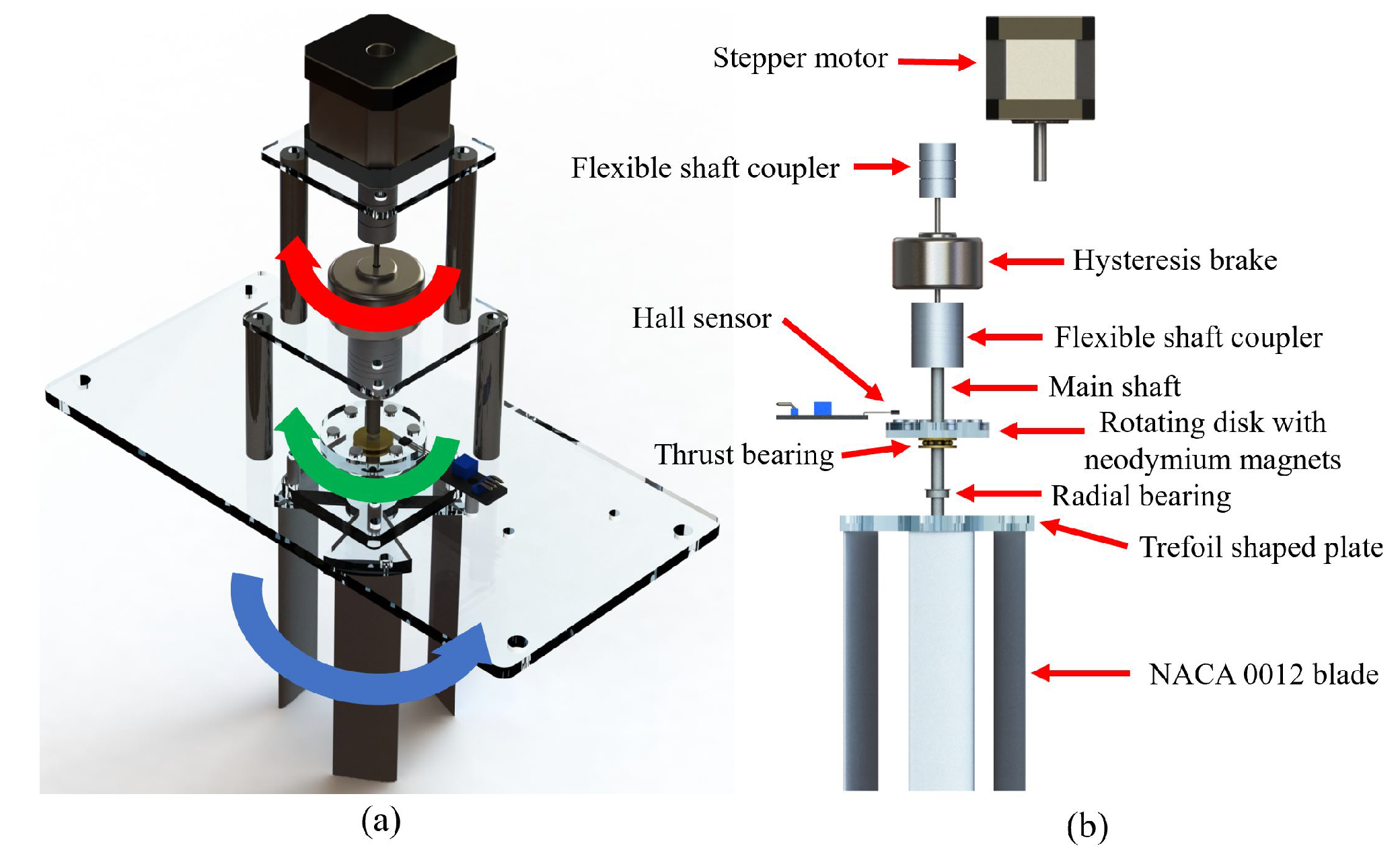
Centered around a Kim Chen Industry double shaft hysteresis brake HB-300A as a turbine speed controller, three variations of the experimental apparatus (single tower, counter-rotating tower, and overlapping tower) were designed and fabricated completely in-house. In the single tower apparatus (Figure 1), the hysteresis brake was mounted vertically on a portable support structure. The lower brake shaft was connected to a circular acrylic disk, which contains six pairs of 2.5 mm diameter neodymium permanent magnets, and a turbine assembly via a flexible aluminum shaft coupler. This shaft was mechanically supported by a radial ball bearing and a thrust roller bearing. On the other side of the brake, the higher shaft can be engaged or disengaged to a Nema 17 stepper motor through another shaft coupler depending on the measurement. The whole single tower was mounted on a 5 mm thick acrylic support plate for easy installation on the water tunnel.
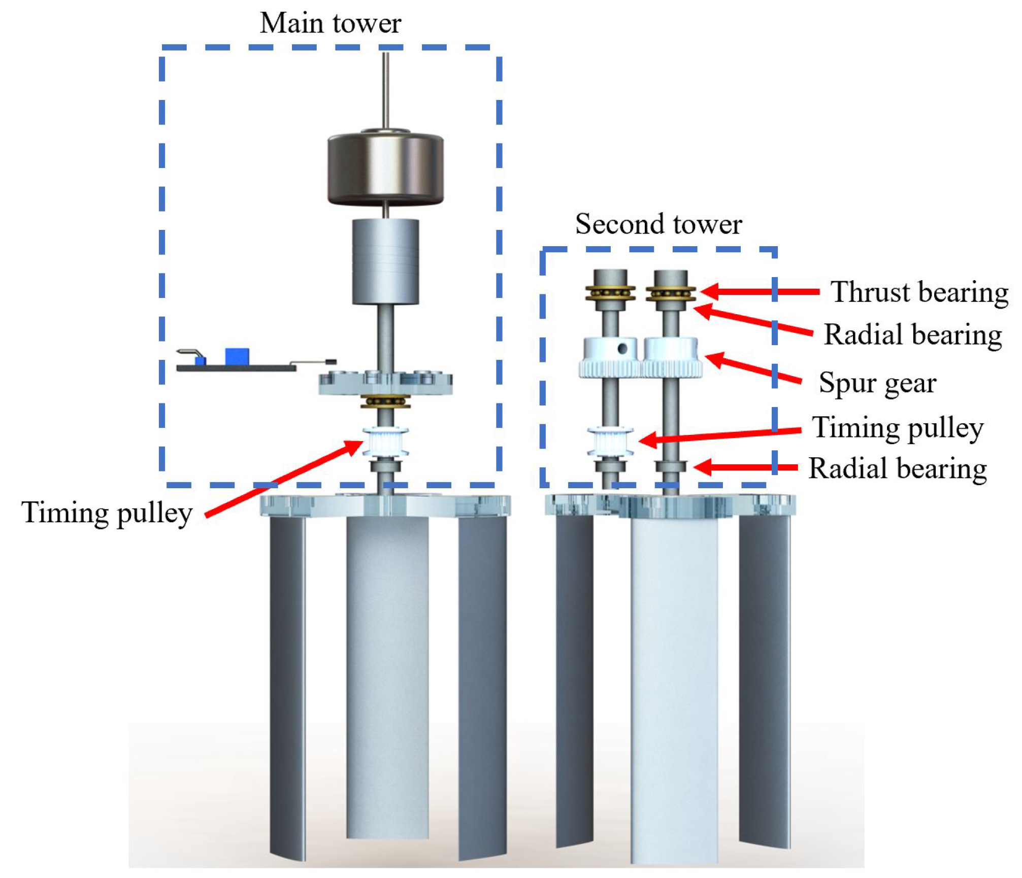
For the twin turbine experiments, the other two variations were implemented by shifting the single tower off center of the support plate and constructing a second tower on the other side of the plate (Figure 2). The second tower consists of two rotating shafts and a drivetrain system. Each shaft was supported by a pair of radial ball bearings and a roller thrust bearing and connected to each other through a pair of aluminum spur gears as shown in Figure 2. The main shaft of this second tower was for mounting a second turbine assembly while the other shaft was linked to the main tower via an S2M timing belt and a pair of pulleys. This drivetrain allowed the 2 turbine shafts to counter-rotate in a synchronized fashion. The only difference between the counter-rotating tower and overlapping tower variation was the center-to-center distance between the turbine shafts.
Two cross-flow turbine assemblies in this study are straight three bladed 6.28 cm diameter rotors. Each turbine blade was manufactured by wire cut electrical discharge machining (EDM) a 10 cm T6061 aluminum block based on the NACA0012 profile at a 2.54 cm chord length. Each blade was bolted at its quarter chord on a trefoil shaped acrylic plate at a 15 pitch angle. The blades were mounted so that the turbine assemblies T1 and T2 rotate in opposite directions given the same incoming flow. The rotor design process firstly started with fixing the blade chord length at 2.54 cm (1 in) similar to the Markovic’s laboratory turbine which operated in a similar flume facility [32]. The NACA0012 profile was chosen due to the popularity of the NACA 4 digit airfoil series in the literature [20,21,35]. Additionally, a previous study of this airfoil family in fluid flow at the chord based Reynolds number below 10,000 suggests that decreasing the airfoil thickness significantly increases its lift-to-drag ratio [36]. A value of 12% of the chosen chord length, which corresponds to the NACA0012 profile, was the minimum thickness that could be manufactured in-house while preserving the airfoil profile accuracy. Secondly, preliminary testing of rotor configurations were conducted with 2, 3, 4, and 6 blades at 0 , 5 , 10 , 15 , and 20 pitch angle. This test proved that a three bladed configuration creates the widest range of operating tip-speed-ratio while pitching the blades at a 15 angle results in enough torque at zero rotational speed so that the turbine can self-start.
On each variation of the experimental apparatus, a Hall effect sensor, which served as a rotational speed transducer, was mounted stationarily to detect the magnetic field of the rotating permanent magnets in the main tower. Power to the Hall sensor was supplied by a general purpose wall plug 100 V/5 V transformer. Other electronics includes a power supply for the hysteresis brake, a controller and power supply for the stepper motor, and data acquisition boards. Regulated DC power supplies Kikusui PMC35-1 and PMC35-2A were used for the brake and motor correspondingly. The NEMA 17 motor was driven by an L298N motor driver and an Arduino Mega micro-controller. Raw electrical signal from the Hall sensor and brake voltage were recorded by two independent National Instrument NI-6000 data acquisition boards, controlled by LabVIEW 2018 on a Dell G3 laptop, at 5 KHz. Water temperature before and after each power measurement was measured and recorded by a type K thermocouple plugged into an A&D AD-5601A digital reader.
During one shaft revolution, each pair of permanent magnets on the rotating disk passed the stationary Hall sensor creating a voltage drop in the raw output signal, as illustrated in Figure 3. Since the 6 pairs of magnets were equally spaced on the acrylic disk at a fixed radius, the shaft rotational speed could be determined by dividing the spacing (1/6 of a full angle between 2 consecutive magnet pairs) by the time difference between the corresponding voltage drops. A Matlab program was developed to post-process this raw signal into time series of the rotational speed. The program firstly recognized the timestamps where each voltage drop fell and rose then averaged them to determine each magnet detection timestamp. The rotating speed was calculated in 2 different ways and compared: using the measured time difference Δ t 1 between 2 consecutive pairs passing the Hall sensor or using the measured time difference Δ t 6 when one pair of magnets made one whole revolution (Figure 3).
Hall sensor data used for evaluating this post-processing program was taken by fixing the stepper motor on the single tower apparatus and spinning the whole system at a constant speed without any turbine assembly. The rotational speed of 200 rpm (20.9 rad/s), which was expected to be approximately the maximum speed of the shaft in all experiments, was input into the Arduino motor driving code. Post-processed data and relevant statistics are summarized in Figure 4. While both ways of post-processing the Hall sensor data gave a mean value of less than 0.05% difference from the expected value, timing one magnet (using Δ t 6 ) was proved to be better in a non-constant rotational speed scenario. Time series of the rotating speed using Δ t 1 created a more than 40 times higher standard deviation. A systematic fluctuation every 6 data points was observed from this data suggesting that the fluctuation came from the uncertainty of spacing between 2 consecutive magnet pairs. Therefore, all data from power and mechanical loss measurements in this paper was post-processed using Δ t 6 . The relative uncertainty associated with this rotational speed measurement was conservatively assumed to be 0.05% for all measured speed below 200 rpm.

2.2. Experimental Procedure

Under power production condition, each apparatus experienced 3 types of torque: hydrodynamic torque created by the water flow (targeted measurement), braking torque due the hysteresis brake, and system mechanical loss due to bearing friction and other damping, as illustrated in Figure 1a. Under the turbine steady state operation, two assumptions could be made: (1) turbine power P is the product of its averaged rotational speed ω ¯ and the hydrodynamic torque T H and (2) the hydrodynamic torque is the sum of the brake torque T B and mechanical loss T M L :
P = T H ω ¯ ,
T H = T M L + T B .
All power measurements with the 3 apparatus variations started and ended with mechanical loss measurements. To perform a mechanical loss measurement of an apparatus, the stepper motor was frictionally engaged on the brake shaft and commanded to rotate at a maximum speed of about 20 rad/s while the brake voltage was kept at zero outside of the water tunnel. Additionally, cylindrical disks with know inertia values were mounted on the turbine shaft. Once the whole shaft reached this maximum value of rotational speed, the motor was disengaged so that the whole system decelerated solely due to its mechanical loss. According to Newton’s Second Law for Rotation, this deceleration is governed by
T M L = I α = I d ω d t ,
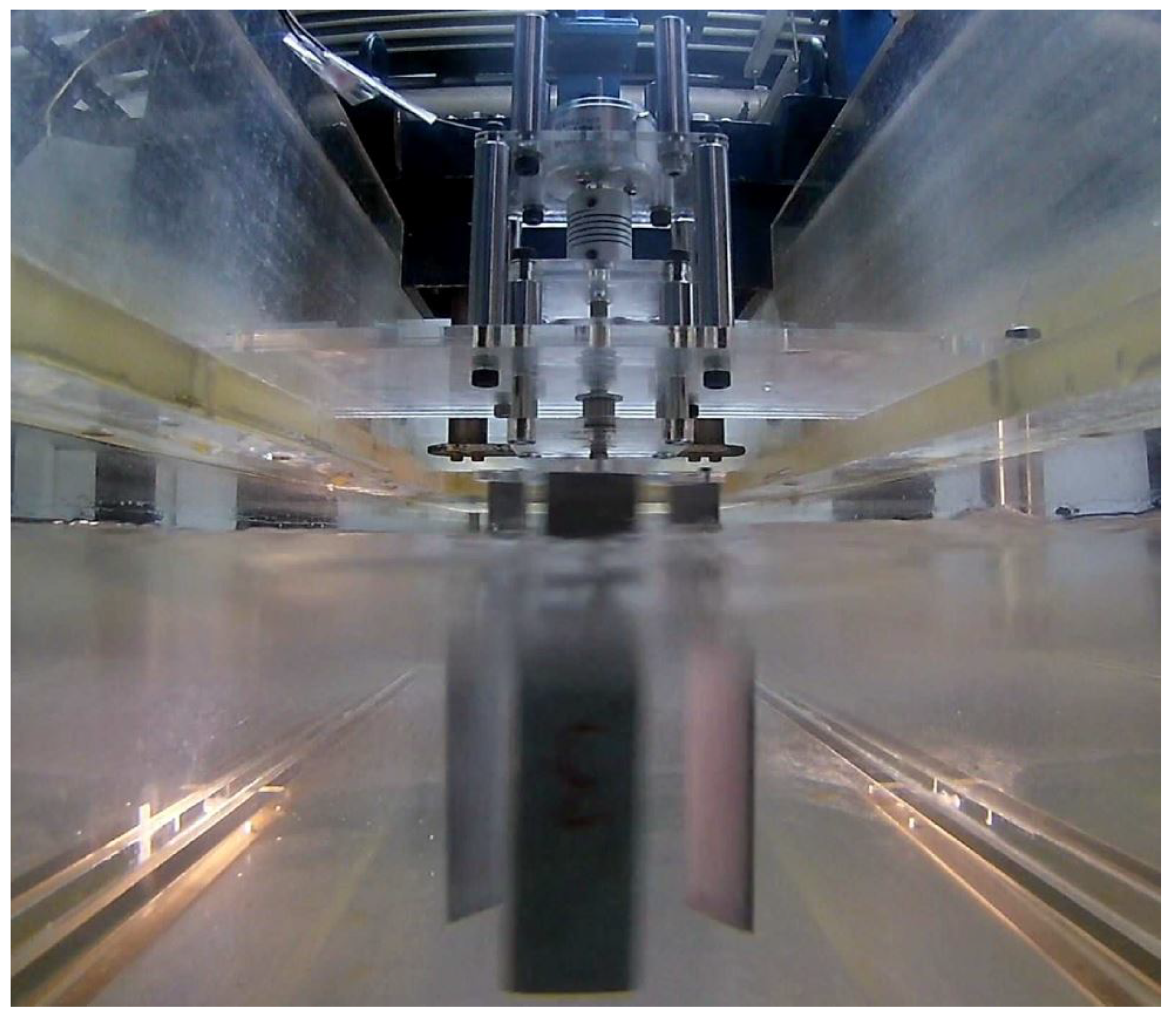
where T M L is the mechanical loss, I is the rotating disk inertia, α is the deceleration, and ω is the rotating speed as a function of the time t. By knowing the inertia mounted on the turbine shaft (without any turbine assembly) and recording its rotating speed decelerating over time, the system mechanical loss could be determined. Since I could have been a dynamic parameter due to the added mass effect if the measurements were performed under water, all mechanical loss experiments were conducted in air. Additionally, only the 3 turbine blades were submerged under water during the power measurement experiments (Figure 5) so that the effect of water on the mechanical support was negligible. In reality, water drag forces on the blades might exert transverse loads on the radial bearing and lead to additional frictional torque. This frictional torque quantity due to water drag on the blades, however, was found to be only within 2% of the lowest measured mechanical loss. Detailed calculation can be seen in Appendix A.
Table-top experiments of turbine power measurement often face with the problem of the system mechanical loss being comparable to the turbine hydrodynamic torque and cannot be neglected. The proposed mechanical loss measurement allowed answering 2 key questions: (1) Is the mechanical loss rotational speed dependent? and (2) Does the amount of weight mounted on the system affect the mechanical loss? To answer these 2 questions, initial mechanical loss study was conducted with various acrylic inertia disks of 3 mm thick and 71.6 mm radius mounted on the single tower apparatus. These dimensions were chosen so that each inertia disk weighted approximately the same as either turbine assembly did.
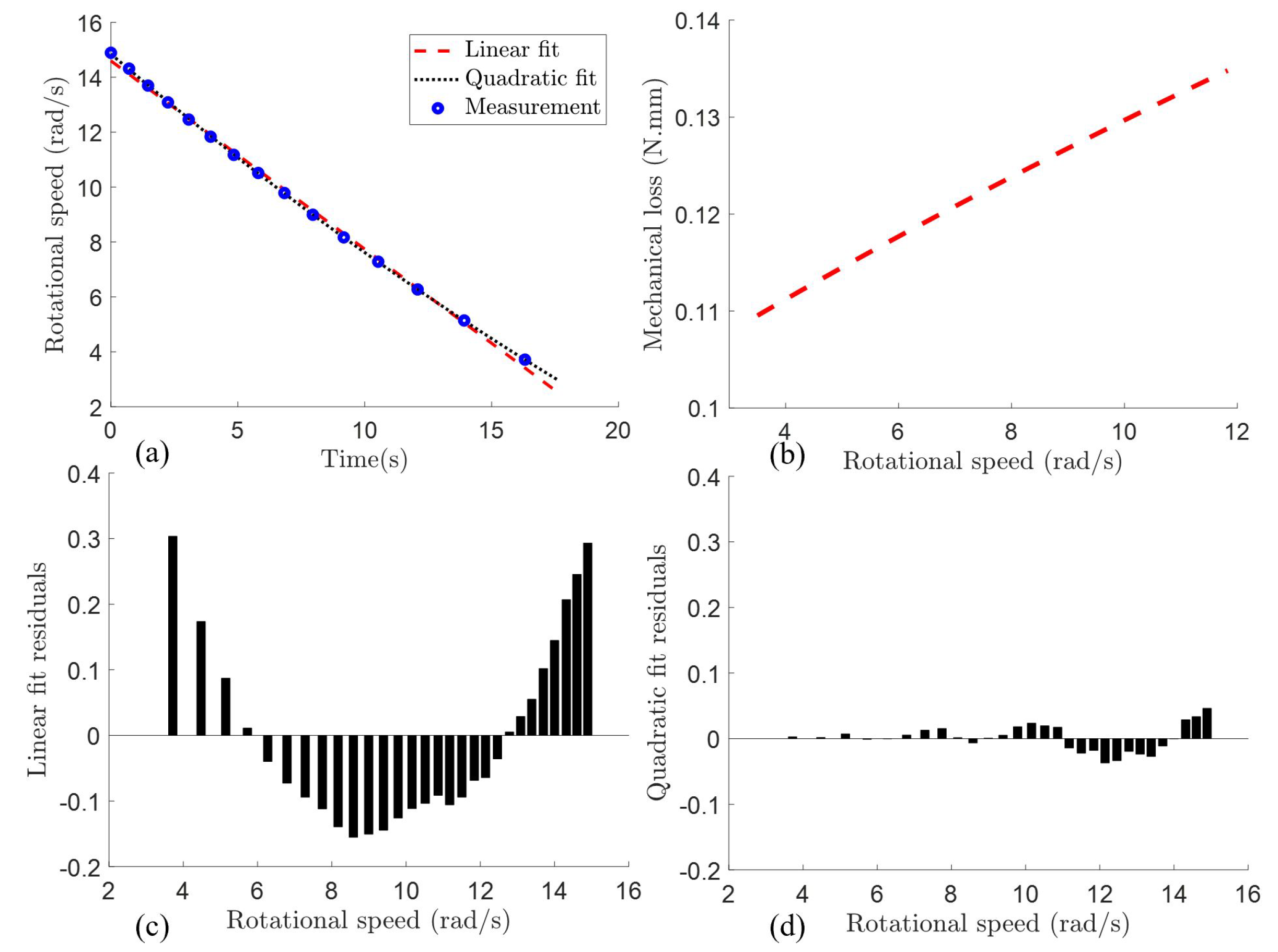
A typical deceleration curve with one inertia disk mounted on the single tower is shown in Figure 6a. The Matlab curve fitting toolbox was used to fit a linear and a quadratic curve through this time series. Calculated residuals from the linear fitting (Figure 6c) were not randomly distributed around zero suggesting that a higher order polynomial function should be used. Therefore, all deceleration curves used for the mechanical loss measurements were fitted with a quadratic model. Dimensional residuals from a second order model, displayed in Figure 6d, were much lower in absolute value and distributed randomly around zero. For each mechanical loss measurement, five deceleration curves were recorded and processed. Another Matlab program was developed to truncate these curves from 15 rad/s, align them at time zero, and fit a quadratic curve through all of the data. From this rotational speed function of time, the deceleration as a function of the speed could be determined and the mechanical loss could be calculated from Equation (3). Figure 6b shows the mechanical loss as a function of the rotating speed with one inertia disk mounted on the single tower apparatus. For the range of expected turbine operating speed (from 4 rad/s up to 12 rad/s), a linear assumption of the deceleration curve could cause more than 10% error in the measured results. The reason behind the mechanical loss being rotational speed dependent can be explained by the fact that the shear stress on the balls and rollers caused by the bearing lubricant are also speed dependent.
Using a quadratic fitting model, the mechanical loss of the single tower apparatus was measured with one, two, three, and four inertia disks (Figure 7). The total mounted masses were measured by a A&D HL-2000 compact scale and the corresponding inertia values were calculated by I = 0.5 m R 2 , where m is the measured mass and R is the disk radius. Figure 7 shows evidence of the system mechanical loss being affected by the amount of mounted mass. This phenomenon can be attributed to higher normal forces being applied on the rollers inside the thrust bearing. Therefore, the system mechanical loss should be measured with an inertia disk whose mass is the same as the turbine mass in an ideal situation. In reality, there were scenarios when the disk inertia was not large enough and decelerated faster than the electronics could capture. More specifically, one inertia mounted on the counter-rotating and overlapping tower apparatus would stop completely after decelerating to around 7 rad/s, which was higher than the expected turbine minimum speed, before the adjacent magnet pair made another whole revolution. In all the twin turbine experiments, the mechanical losses were measured with 4 inertia disks and corrected using data shown in Figure 7. The effect of difference in inertia values between the disks and the turbines is proved to be negligible in Appendix B.
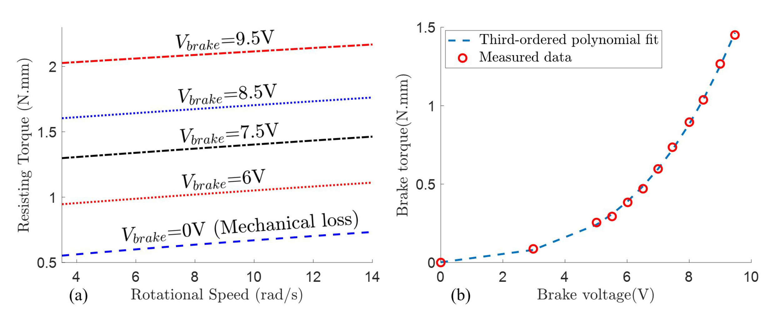
While the brake voltage was kept zero in all mechanical loss measurements, the exact same procedure could be used to directly measure the brake curve. The brake voltage was input to be 0 V, 3 V, 5 V, and from 5 V to 9.5 V with a 0.5 V increment and the deceleration curves were recorded with an aluminum alloy (A2017P) inertia disk of 10 mm thick and 150 mm of diameter mounted on the single tower apparatus. The deceleration curves were post-processed to determine the total resisting torque in the system (Figure 8a). By offsetting these torque values by the measured value at 0 V (mechanical loss), the brake torque as a function of its input voltage was determined (Figure 8b). Figure 8a illustrates that the resisting torque curves are parallel to the mechanical loss curve. Although the mechanical loss was rotating speed dependent, the differences between these parallel curves were constant indicating that the brake torque was speed independent. A third-order polynomial was fitted through these measured brake torque values as a function of the input voltages and was used to determine the brake torque for all power coefficient measurements.
Once the mechanical loss could be directly measured and the brake torque at any specific input voltage was known, the turbine power coefficient C p can be evaluated, under the 2 previously stated assumptions (Equations (1) and (2)), by
C p = T H ω ¯ 1 2 ρ A U 3 ,
where ρ is the water density, A is the system frontal area, and U is the reference inlet velocity. The frontal area A was defined as D t h for the single turbine and 2 D t h for the twin turbine configurations, where D t is the rotor diameter and h is the height that the blades were submersed in water. All 3 variations of the apparatus were mounted in the channel so that the trefoil plates hovered around 2 cm above the water free surface while all the bearings and shaft stayed outside of the water. The system power coefficient C p was measured and compared between different turbine configurations at various relative distances and phase angle differences Δ Φ for the twin turbine system.
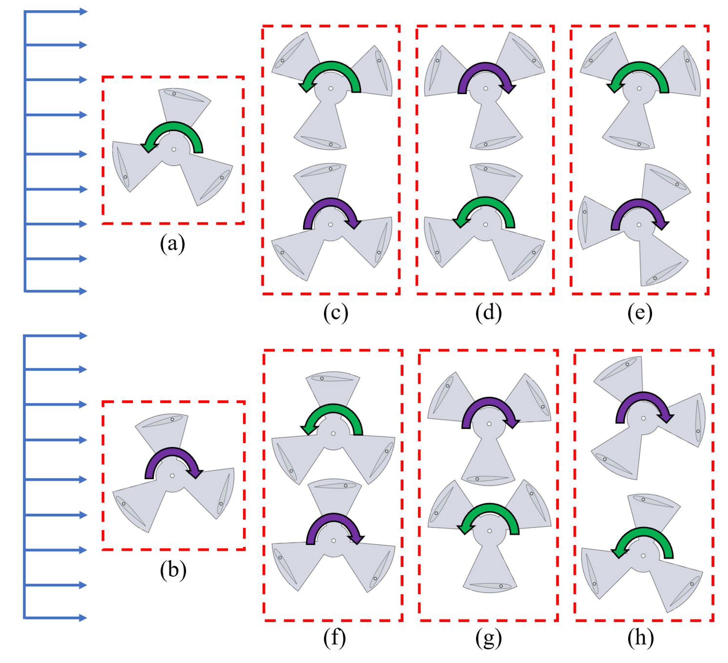
A total of 8 different configurations, as shown in Figure 9 were examined including: single turbine T1, single turbine T2, T1 and T2 forward counter-rotating at Δ Φ = 0 , T1 and T2 backward counter-rotating at Δ Φ = 0 , T1 and T2 forward counter-rotating at Δ Φ = 60 , T1 and T2 backward counter-rotating at Δ Φ = 60 , T1 and T2 forward overlapping at Δ Φ = 60 , and T1 and T2 backward overlapping at Δ Φ = 60 . Turbine T1 and T2 had their 3 blades arranged to rotate counter-clockwise and clockwise respectively in the convention of the water flowing from left to right. The turbine phase angle Φ was defined as the angle between the turbine x-axis to its nearest blade quarter chord, while the turbine x-axis points from the turbine center to the position where a blade achieves its maximum local chord based Reynolds number. The forward and backward conventions are for configurations where the turbine blade at Φ = 180 moves in the same and opposite direction correspondingly with respect to the incoming flow. The turbine center-to-center distance of the counter-rotating and overlapping configurations are 1.25 D t and 1.00 D t respectively. The 6 twin turbine configurations were chosen as a combination of 2 relative incoming flow angles, 2 phase angle differences, and 2 separation distances.

3. Results and Discussion

For each configuration, the mechanical loss was measured before and after each measurement session and averaged since it could be affected by the ambient temperature, misalignment of the bearings, and bearing lubricant temperature. In each data set, the brake voltage was increased from 0V until turbine stall so that the data points were roughly spread evenly on the tip-speed-ratio λ = ω R t / U (where R t is the rotor radius) space. Three data sets were taken for each measurement session and a total of 5 sessions were conducted by 2 operators for each configuration. For each data point, the turbine rotational speed was recorded for one minute yielding more than 50 rotations for the minimum expected speed. Water temperature was also recorded before and after each data set; and the water density was linear interpolated between these temperature values based on a textbook water density table [37].
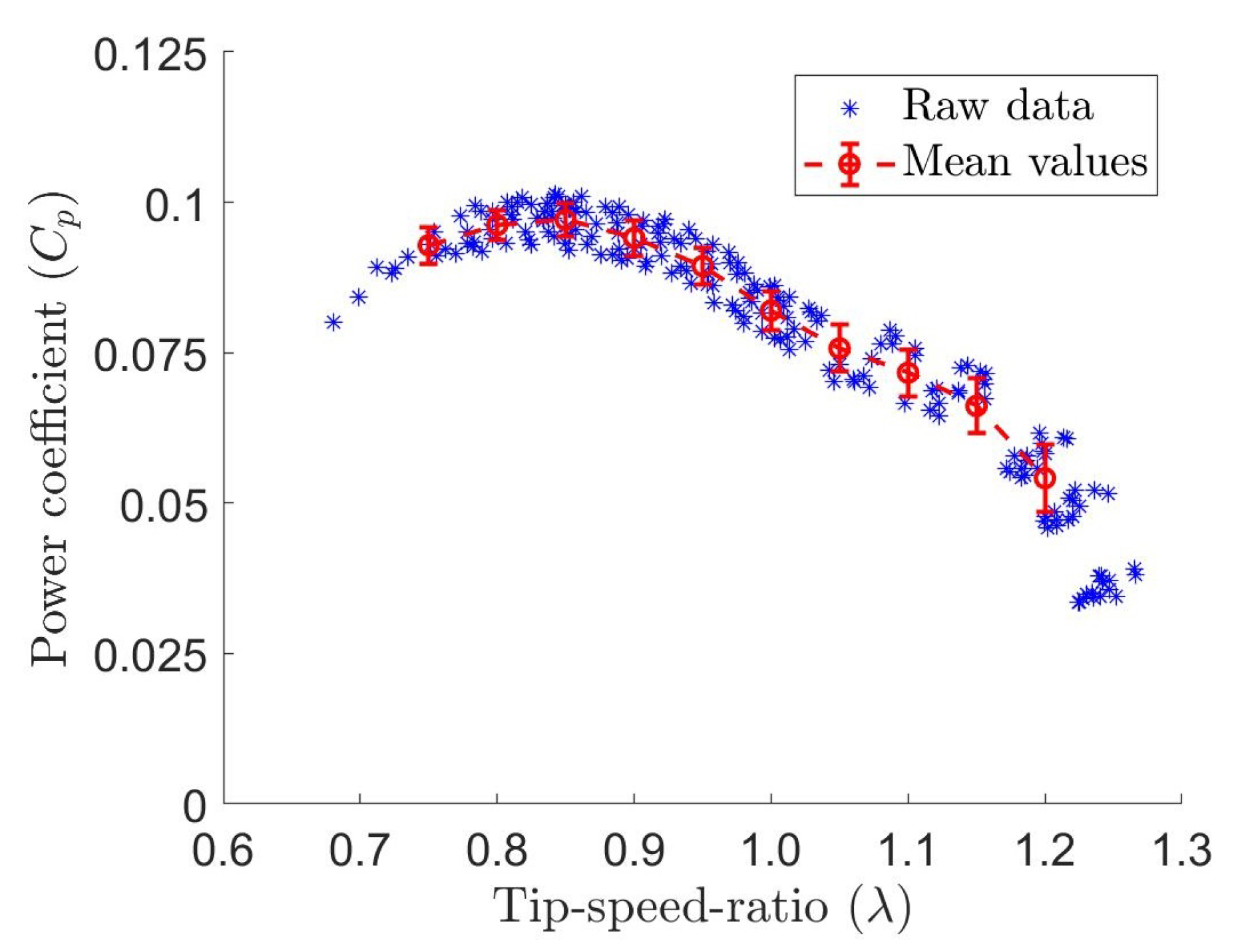
All the mechanical loss measurements associated with the single turbine experiment were conducted with one inertia disk ( m 1 and I 1 in Figure 7) which had the exact same weight as turbine T1 and T2. An example of the power measurement raw data from the 15 data sets for one single turbine can be seen in Figure 10. The data was further processed by interpolating each set at an equal distance in the λ space and averaging the interpolated curves. The averaged curve covers only the range of λ that was captured by all the 15 sets. The error bars in Figure 10 are the standard deviation of the mean from the 15 data sets.
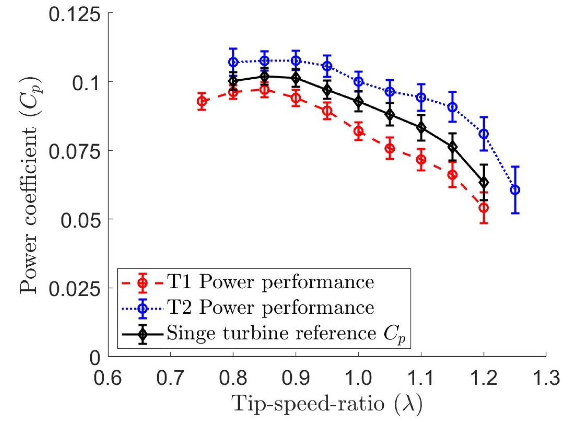
The processed power measurement results of a single turbine are summarized in Figure 11. Turbine T2 showed a slightly better performance compared to turbine T1, which could be attributed to differences in manufacturing and assembly. The wire cut EDM process created inconsistency in the blade surface roughness and defects near the sharp trailing edge which could affect the hydrodynamic forces. Additionally, the pitch angle was determined by aligning the blades with laser engraved profiles on the 2 trefoil plates that could deviate up to ± 0 . 28 from the desired 15 angle. Therefore, the power curves of T1 and T2 were averaged in Figure 11 to be compared with the twin turbine configurations. The reference curve reached its maximum C p value of 0.102 at λ = 0.85 with a 2.9% uncertainty.
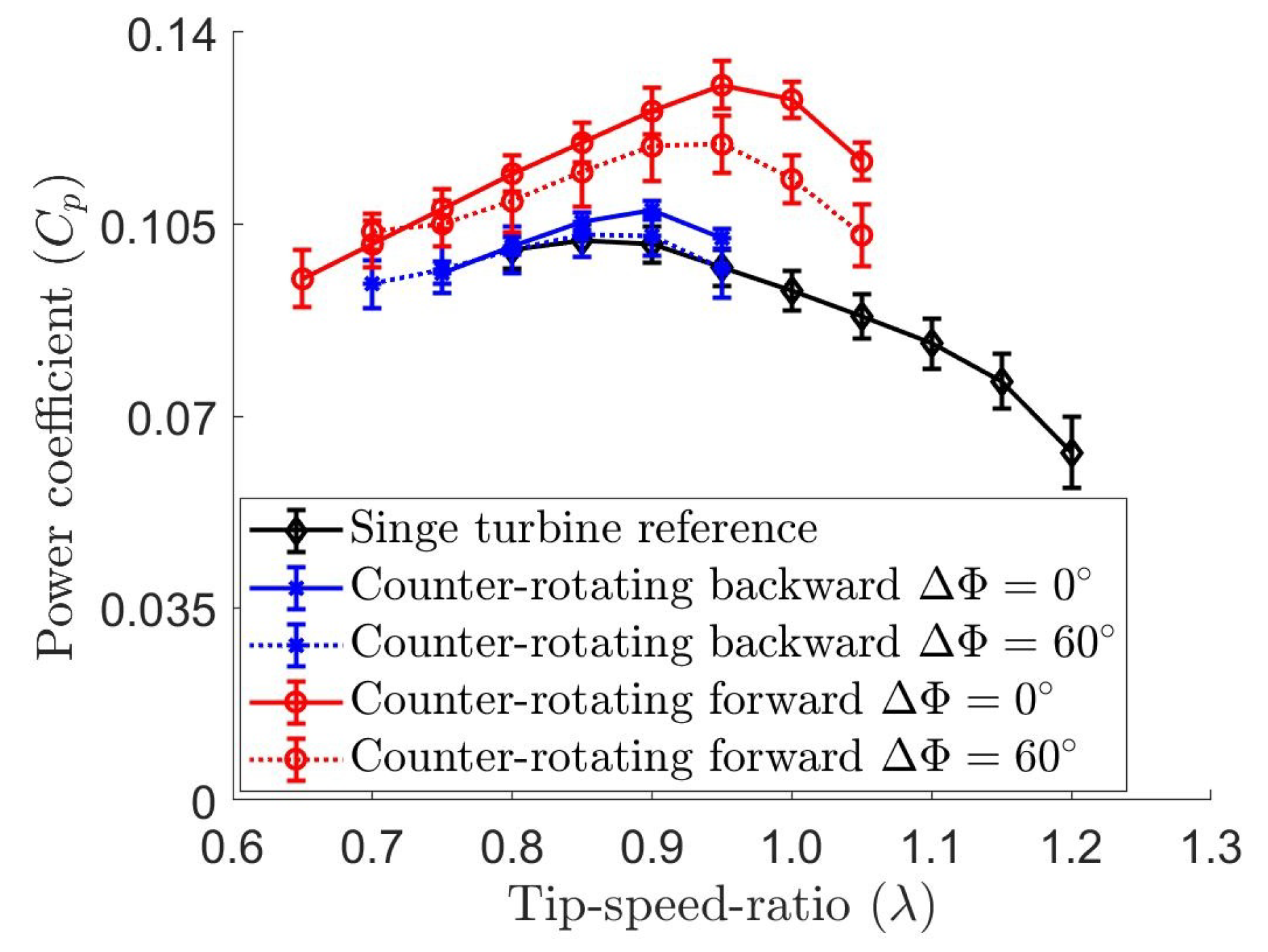
The mechanical loss of the counter-rotating tower apparatus was measured using 4 inertia disks so that the turbine range of operating speed was captured in the deceleration curve. Specifically, m 1 / I 1 (in Figure 7) was mounted on the second tower and m 3 / I 3 was connected to the main tower shaft. The final mechanical loss used for power coefficient calculation was corrected based on the turbine masses and the offset in Figure 7. When the 2 turbines operated in the counter-rotating configurations, the system power performance was observed to have different tendency at different relative incoming flow directions and turbine phase angle differences (Figure 12). Since all of the 4 counter-rotating configurations had the same blockage ratio and separation distance between the turbines, the interaction between the blades could be concluded to play an important role in the overall system power production.
Previous computational dynamic analyses for these configurations published in [22,23,34] showed that each blade entered its positive torque phase at approximately the phase angle from 30 to 185 . Additionally, the gap between the turbines could be expected to act like a nozzle that accelerated the flow. This fast flow zone effectively increased the the streamwise velocity on the blade pressure side while reducing the fluid pressure. In the counter-rotating forward configurations, each blade entered this accelerating flow zone during the later part of its positive torque phase in the vicinity of the minimum chord based Renoylds number R e c . On the other had, each blade switched from its negative to positive torque phase, in the vicinity of its maximum R e c , in the the counter-rotating backward configurations. At the same phase difference, Figure 12 shows that the forward configurations produced more power output at a slightly higher tip-speed-ratio compared to the backward configurations, which indicated that the accelerated flow zone created positive effect in the low R e c vicinity of the positive torque phase. Moreover, due to the blade direction of movement in this zone, the forward configurations created a faster flow compared to the backward configurations. At the same relative incoming flow direction (either forward or backward), 0 phase difference was observed to be better than 60 in terms of power production. Due to the geometric constrains created by the turbine blades, 0 phase difference could be expected to produce a faster accelerated flow zone which again indicated that a faster flow zone was better for the system power output.
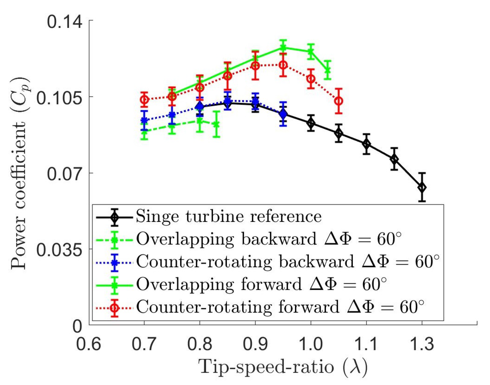
The mechanical loss of the overlapping tower apparatus was also measured using 4 inertia disks. Due to turbine separation distance (62.8 mm) being smaller than the inertia disk radius (71.6 mm), all the 4 inertia disks ( m 4 / I 4 in Figure 7) were mounted on the main tower. The power measurement of overlapping configurations at Δ Φ = 60 compared with the counter-rotating forward and backward configurations at the same phase difference are summarized in Figure 13. In terms of the relative incoming flow, the forward configuration again showed better power production than the backward configuration. The overlapping backward arrangement of turbines produced about 9% less power than the counter-rotating backward configuration did. In the overlapping configurations, one turbine blade also operated in the wake of the other turbine blade in the fast flow zone. At the same phase angle difference of the forward configurations, reducing the separation distance (from counter-rotating 1.25 D = t to overlapping 1.00 D t ) which accelerated the flow faster also increased the system power performance.
The maximum recorded power coefficients of all the configurations are display in Table 1. Compared with the single turbine reference value, all of the twin system configurations, except for overlapping backward, produced higher power output given the same input energy. Other than the blade interaction in the accelerated flow zone discussed above, the increase in C p value from one single turbine could also be attributed to the increase in blockage ratio from 19.75% to 39.5%. An experimental corrected power coefficient would require other flow measurements and will be included in a future publication. The value of these results still remain in implementation of multiple devices in a river flow scenario. The turbine separation distance and phase angle difference can be manipulated to maximize the positive blade interaction effect.

4. Conclusions

An economical apparatus design and a novel method to measure the power production performance of a laboratory-scaled marine hydrokinetic turbine system were proposed and implemented in this study. Using a single Hall effect sensor, this methodology can be applied to measurements of the mechanical loss in any rotating mechanical system, the torque generated by an electromagnetic brake, and the hydrodynamic torque exerted on an MHK turbine.
The mechanical loss measurements showed that frictional torque due to bearings are rotational speed dependent and a simple linear assumption of the system deceleration curve (or constant deceleration and constant resisting torque) could lead to more than 10% error in measurements. When thrust bearings are involved, the mechanical loss measurements also depend on the amount of mass mounted on the system and should be accounted for in the final turbine power measurement. Experimental evidence also showed that the resisting torque generated by the hysteresis brake was speed independent.
Using the proposed power measurement methodology, six different twin turbine configurations were tested at two different relative incoming flow angles, two phase angle differences, and two different turbine separation distances. Among these configurations, the interaction between the turbine blades largely affected the system overall power performance. Evidence from this study showed that the streamwise velocity of the accelerated flow zone in between the twin turbines should be maximized to enhance the system power output. The turbine should also be arranged in a fashion that their blades are in the vicinity of their minimum chord based Reynolds number when going through this fast flow zone. Further optimization of these counter-rotating configurations require relevant flow field information which can be obtained by a particle image velocimetry technique in future experiments. Once the relevant flow fields associated with different configurations are obtained, a blockage ratio correction for the single turbine power coefficient can also be applied, using one of the methods discussed in [38], and compared with the twin turbine system result at the same blockage ratio. Nevertheless, counter-rotating configurations of MHK turbines can be made use of to enhance the system power output in a scenario where space is confined.
Values of the proposed method also remain in rapid prototyping and comparing the power production of different turbine configurations. Compared to popular methods that use optical sensors, light sources, and load cells, the proposed design includes no electronic components that are attached on the rotating parts and therefore requires no implementation of slip-rings on the shaft. By taking advantages of multiple permanent magnets mounted on the rotor, magnetic sensors can be fixed on the stationary structural frame and the torque values can be calculated based on solely the speed measurements. Direct comparison between this method and the conventional methods in terms of accuracy, cost, and implementation time is hoped to be done in future work.

Author Contributions

Conceptualization, M.N.D. and S.O.; methodology, M.N.D. and Y.K.; software, M.N.D. and Y.K.; validation, M.N.D. and Y.K.; formal analysis, M.N.D.; investigation, M.N.D. and Y.K.; resources, S.O.; data curation, M.N.D.; writing—original draft preparation, M.N.D. and S.O.; writing—review and editing, S.O.; visualization, M.N.D.; supervision, S.O.; project administration, S.O.; funding acquisition, S.O. All authors have read and agreed to the published version of the manuscript.

Funding

This research received no external funding.

Acknowledgments

M.N.D. thanks Ivan Alayeto, Kana Kumazawa, Claudio Padricelli, Keita Ando, Uros Markovic, Naomichi Baba, Naoya Sumimura, Julio Barros, Anna Mizobuchi, Mehdi Badri, and Laura Beninati for fruitful discussions and help with the experimental setup. The authors also thank Hisae Mizuno for her endless help with the grant and logistics paperwork. This research was supported by the Keio Design The Future award and the Keio Doctoral Student Grant-in-aid program.

Conflicts of Interest

The authors declare no conflict of interest. The funders had no role in the design of the study; in the collection, analyses, or interpretation of data; in the writing of the manuscript, or in the decision to publish the results.

Abbreviations

The following abbreviations are used in this manuscript:
MHKMarine hydrokinetic turbine
EDMElectrical discharge machining
VAWTVertical axis wind turbine
LDVLaser Doppler velocimetry

Appendix A. Estimation of the Effect on the Measured Mechanical Loss Due to Water Drag on the Turbine

There is a possibility that the water drag forces on the 3 blades create transverse loads on the radial ball bearing and therefore induce additional mechanical losses. The drag force on each blade can be evaluated by F D = 1 2 ρ C d A U 2 , where all of the relevant parameters and their values are given in Table A1. In the worst case scenario when one blade is positioned at 90 angle of attack with respect to the relative incoming flow U , the drag force F D is computed to be 0.142 N. This computation assumed a drag coefficient C d of 1.4, taken from [39], and a frontal area A as the product of the blade chord length (2.54 cm) and its submerged depth (8 cm). If all 3 blades experienced this maximum drag value at the same time, the additional mechanical loss (frictional torque by the bearing) woudl be T f = 3 μ b F D D b 2 giving an additional loss of 1.6 × 10 3 N · mm which is less than 1.5% of the measured mechanical loss and can be negligible. The bearing frictional coefficient value was retrieved from [40].
Table A1. Comparison of each configuration maximum recorded power coefficient.
ParameterValueUnit
Water density ρ 998 kg / m 3
Drag coefficient C d 1.4-
Freestream velocity U 0.3158m/s
Frontal area A20.32 cm 2
Bearing nominal diameter D b 5mm
Bearing frictional coefficient μ b 0.0015-

Appendix B. Estimation of the Effect on the Measured Mechanical Loss Due Turbine Mass Distribution

There is also a possibility that the centrifugal force due to turbine rotation can exert an additional transverse force on the radial bearing and therefore induce a frictional torque. Although the dependence of the system mechanical loss on the turbine rotational speed was examined in the main article, this section concerns about the effect of the mass distribution (or the inertia) around the rotating axis on the mechanical loss. The centrifugal force on the rotating shaft can be calculated as F c = m a = m ω 2 r . Assuming all the turbine mass m of 59 g (in the worst case scenario) was concentrated at the turbine radius of 34.14 mm, the centrifugal force would be 0.29 N at the system maximum rotational speed ω of 12 rad/s. The associated frictional torque can be then calculated by T f = μ b F c D b 2 giving a value of 1.1 × 10 3 N · mm which is less than 1% of the measured mechanical loss and can be negligible. The relevant values of μ b and D b are given and explained in Table A1.

References

  1. Narune, A.; Prasad, E. Renewable Energy Market by Type (Hydroelectric Power, Wind Power, Bioenergy, Solar Energy, and Geothermal Energy), and End Use (Residential, Commercial, Industrial, and Others): Global Opportunity Analysis and Industry Forecast, 2018–2025; Report EN 17140; Allied Market Research: Portland, OR, USA, 2019. [Google Scholar]
  2. Wu, J.; Huang, J.; Han, X.; Xie, Z.; Gao, X. Ecology: Three-Gorges dam experiment in habitat fragmentation? Science 2003, 300, 1239–1240. [Google Scholar] [CrossRef] [PubMed]
  3. Jackson, S.; Sleigh, A. Resettlement for China’s Three Gorges Dam: Socio-economic impact and institutional tensions. Communist Post Communist Stud. 2000, 33, 223–241. [Google Scholar] [CrossRef]
  4. Tilt, B.; Braun, Y.; He, D. Social impacts of large dam projects: A comparison of international case studies and implications for best practice. J. Environ. Manag. 2009, 90, S249–S257. [Google Scholar] [CrossRef] [PubMed]
  5. Adhikari, R.; Wood, D. The design of high efficiency crossflow hydro turbines: A review and extension. Energies 2018, 11, 267. [Google Scholar] [CrossRef] [Green Version]
  6. Adhikari, R.; Wood, D. A new nozzle design methodology for high efficiency crossflow hydro turbines. Energy Sustain. Dev. 2017, 41, 139–148. [Google Scholar] [CrossRef]
  7. Joshi, C.; Seshadi, V.; Singh, S. Parametric study on performance of cross-flow turbine. J. Energy Eng. 1995, 121, 28–45. [Google Scholar] [CrossRef]
  8. Bachant, P.; Wosnik, M. Performance measurements of cylindrical- and spherical-helical cross-flow marine hydrokinetic turbines, with estimates of exergy efficiency. Renew. Energy 2014, 74, 318–325. [Google Scholar] [CrossRef]
  9. Bachant, P.; Wosnik, M.; Gunawan, B.; Neary, V. Experimental study of a reference model vertical-axis cross-flow turbine. PLoS ONE 2016, 11, e0163799. [Google Scholar] [CrossRef] [Green Version]
  10. Bachant, P.; Wosnik, M. Effects of Reynolds number on the energy conversion and near-wake dynamics of a high solidity vertical-axis cross-flow turbine. Energies 2016, 9, 73. [Google Scholar] [CrossRef] [Green Version]
  11. Strom, B.; Brunton, S.; Polagye, B. Intracycle angular velocity control of cross-flow turbines. Nat. Energy 2017, 2, 1–9. [Google Scholar] [CrossRef]
  12. Lust, E.; Flack, K.; Luznik, L. Survey of the near wake of an axial-flow hydrokinetic turbine in quiescent conditions. Renew. Energy 2018, 129, 92–101. [Google Scholar] [CrossRef]
  13. Lust, E.E. The Influence of Surface Gravity Waves on the Performance and Near-Wake of an Axial-Flow Marine Hydrokinetic Turbine. Ph.D. Thesis, University of Maryland, College Park, MD, USA, 2017. [Google Scholar]
  14. Sanchit, S.; Oumnia, E.F.; Shanti, B.; David, T.; Daphne, O.; Tim, O.; Allan, M.J. Validation of Tidal Stream Turbine Wake Predictions and Analysis of Wake Recovery Mechanism. J. Mar. Sci. Eng. 2019, 7, 362. [Google Scholar]
  15. Gaurier, B.; Carlier, C.; Germain, G.; Pinon, G.; Rivoalen, E. Three tidal turbines in interaction: An experimental study of turbulence intensity effects on wakes and turbine performance. Renew. Energy 2019, 1468, 1150–1164. [Google Scholar] [CrossRef]
  16. Scarlett, G.T.; Viola, I.M. Unsteady hydrodynamics of tidal turbine blades. Renew. Energy 2019, 146, 843–855. [Google Scholar] [CrossRef]
  17. Vinod, A.; Banerjee, A. Performance and near-wake characterization of a tidal current turbine in elevated levels of free stream turbulence. Appl. Energy 2019, 254, 113639. [Google Scholar] [CrossRef] [Green Version]
  18. Kim, S.J.; Singh, P.M.; Hyun, B.S.; Lee, Y.H.; Choi, Y.D. A study on the floating bridge type horizontal axis tidal current turbine for energy independent islands in Korea. Renew. Energy 2017, 112, 35–43. [Google Scholar] [CrossRef]
  19. Guo, X.; Gao, Z.; Li, X.; Yang, J.; Moan, T. Loading and Blade Deflection of a Tidal Turbine in Waves. J. Offshore Mech. Arct. Eng. 2019, 141, 041902. [Google Scholar] [CrossRef]
  20. Bachant, P.; Wosnik, M. Modeling the near-wake of a vertical-axis cross-flow turbine with 2-D and 3-D RANS. J. Renew. Sustain. Energy 2016, 8, 053311. [Google Scholar] [CrossRef] [Green Version]
  21. Mannion, B.; Leen, S.; Nash, S. A two and three-dimensional CFD investigation into performance prediction and wake characterisation of a vertical axis turbine. J. Renew. Sustain. Energy 2018, 10, 034503. [Google Scholar] [CrossRef]
  22. Doan, M.N.; Alayeto, I.H.; Kumazawa, K.; Obi, S. Computational fluid dynamic analysis of a marine hydrokinetic crossflow turbine in low Reynolds number flow. In Proceedings of the ASME-JSME-KSME 2019 8th Joint Fluids Engineering Conference, San Francisco, CA, USA, 28 July–1 August 2019; American Society of Mechanical Engineer: New York, NY, USA, 2019; Volume 2, p. V002T02A067. [Google Scholar]
  23. Alayeto, I.H.; Doan, M.N.; Kumazawa, K.; Obi, S. Wake characteristics comparison between isolated and pair configurations of marine hydrokinetic crossflow turbines at low Reynolds numbers. In Proceedings of the ASME-JSME-KSME 2019 8th Joint Fluids Engineering Conference, San Francisco, CA, USA, 28 July–1 August 2019; American Society of Mechanical Engineer: New York, NY, USA, 2019; Volume 1, p. V001T01A037. [Google Scholar]
  24. Mannion, B.; McCormack, V.; Leen, S.; Nash, S. A CFD investigation of a variable-pitch vertical axis hydrokinetic turbine with incorporated flow acceleration. J. Ocean Eng. Mar. Energy 2019, 5, 21–39. [Google Scholar] [CrossRef] [Green Version]
  25. Lande-Sudall, D.; Stallard, T.; Stansby, P. Co-located deployment of offshore wind turbines with tidal stream turbine arrays for improved cost of electricity generation. Renew. Sustain. Energy Rev. 2019, 104, 492–503. [Google Scholar] [CrossRef]
  26. Dabiri, J. Potential order-of-magnitude enhancement of wind farm power density via counter-rotating vertical-axis wind turbine arrays. J. Renew. Sustain. Energy 2011, 3, 043104. [Google Scholar] [CrossRef] [Green Version]
  27. Li, Y.; Calisal, S. Modeling of twin-turbine systems with vertical axis tidal current turbines: Part 1—Power Output. Ocean Eng. 2010, 37, 627–637. [Google Scholar] [CrossRef]
  28. Li, Y.; Calisal, S. Modeling of twin-turbine systems with vertical axis tidal current turbine: Part 2—Torque Fluctuation. Ocean Eng. 2011, 38, 550–558. [Google Scholar] [CrossRef]
  29. Brownstein, I.D.; Wei, N.J.; Dabiri, J.O. Aerodynamically Interacting Vertical-Axis Wind Turbines: Performance Enhancement and Three-Dimensional Flow. Energies 2019, 12, 2427. [Google Scholar] [CrossRef] [Green Version]
  30. Jiang, Y.; Zhao, P.; Stoesser, T.; Wang, K.; Zhou, L. Experimental and numerical investigation of twin vertical axis wind turbines with a deflector. Energy Convers. Manag. 2020, 209, 112588. [Google Scholar] [CrossRef]
  31. Javaherchi, T.; Stelzenmuller, N.; Aliseda, A. Experimental and numerical analysis of the performance and wake of a scale–model horizontal axis marine hydrokinetic turbine. J. Renew. Sustain. Energy 2017, 9, 044504. [Google Scholar] [CrossRef]
  32. Markovic, U.V. Characterizing the Wake and the Performance of a Marine Hydrokinetic Turbine in a Tandem Array Configuration. Master’s Thesis, Bucknell University, Lewisburg, PA, USA, 2016. [Google Scholar]
  33. Mannion, B.; McCormack, V.; Kennedy, C.; Leen, S.; Nash, S. An experimental study of a flow-accelerating hydrokinetic device. Proc. Inst. Mech. Eng. Part A J. Power Energy 2018, 1, 148–162. [Google Scholar] [CrossRef] [Green Version]
  34. Doan, M.N.; Alayeto, I.H.; Padricelli, C.; Obi, S.; Totsuka, Y. Experimental and computational fluid dynamic analysis of laboratory-scaled counter-rotating cross-flow turbines in marine environment. In Proceedings of the ASME 2018 5th Joint US-European Fluids Engineering Division Summer Meeting, Montreal, QC, Canada, 15–20 July 2018; American Society of Mechanical Engineer: New York, NY, USA, 2018; Volume 2, p. V002T14A003. [Google Scholar]
  35. Tsai, H.C.; Colonius, T. Coriolis Effect on Dynamic Stall in a Vertical Axis Wind Turbine. AIAA J. 2016, 54, 216–226. [Google Scholar] [CrossRef] [Green Version]
  36. Kunz, P. Aerodynamics and Design for Ultra-Low Reynolds Number Flight. Ph.D. Thesis, Stanford University, Stanford, CA, USA, 2003. [Google Scholar]
  37. White, F. Fluid Mechanics 8th Edition in SI Units, Table A1 738–739; McGraw-Hill Education (Asia): Singapore, 2016. [Google Scholar]
  38. Ross, H.; Polagye, B. An experimental assessment of analytical blockage corrections for turbines. Renew. Energy 2020, 152, 1328–1341. [Google Scholar] [CrossRef] [Green Version]
  39. Montgomerie, B. Drag Coefficient Distribution on a Wing at 90 Degrees to the Wind; Technical Report ECN-C-95-061; Netherlands Energy Research Foundation: Petten, The Netherlands, 1996. [Google Scholar]
  40. JTEKT. Frictional Coefficient (Reference). Retrieved from JTEKT Corporation Website. 2020. Available online: https://koyo.jtekt.co.jp/en/support/bearing-knowledge/8-4000.html (accessed on 2 November 2020).
Sample Availability: All results in numeric are available from the authors.
Figure 1. A 3D rendered picture of the single tower apparatus (a) showing the three types of torque exerted on the system: hydrodynamic torque (positive in blue), brake torque (negative in red), and mechanical loss (negative in green) and critical mechanical components (b). The stepper motor can be frictionally or permanently (via two M3 set screws) engaged to the system through a shaft coupler.
Jmse 08 00918 g001
Figure 2. Critical mechanical components of the counter-rotating and overlapping tower apparatus. The drivetrain consists of a pair of aluminum spur gears and 2 timing pulleys connected to each other by a S2M timing belt.
Jmse 08 00918 g002
Figure 3. Illustration of the Hall sensor raw output signal when the shaft was rotating constantly at 120 rpm. Each magnetic field detection by the sensor created a voltage drop in the signal.
Jmse 08 00918 g003
Figure 4. An example of the processed rotational speed with Δ t 1 and Δ t 6 .
Jmse 08 00918 g004
Figure 5. Picture of the single turbine apparatus in the water channel test section.
Jmse 08 00918 g005
Figure 6. (a) An example of the deceleration curve with one inertia disk on the single tower apparatus with linear and quadratic fitted curves. (b) The post-processed mechanical loss curve as a function of the system rotating speed. Fitting deviation from the measured data with a linear fit (c) and a quadratic fit (d). To be clearly displayed only one every ten data points in (a) and one every five data points in (c) and (d) are being shown.
Jmse 08 00918 g006
Figure 7. Measured mechanical losses of the single tower apparatus with different mounted masses.
Jmse 08 00918 g007
Figure 8. (a) An example of the system resisting torque measured at different brake voltage and (b) the measured HB-300 hysteresis brake torque curve as a function of the input voltage.
Jmse 08 00918 g008
Figure 9. Different turbine configurations used in the power measurement experiment: (a) Single turbine T1, (b) Single turbine T2, (c) Forward counter-rotating at Δ Φ = 0 , (d) Backward counter-rotating at Δ Φ = 0 , (e) Forward counter-rotating at Δ Φ = 60 , (f) Forward overlapping at Δ Φ = 60 , (g) Backward overlapping at Δ Φ = 60 , and (h) Backward counter-rotating at Δ Φ = 60 .
Jmse 08 00918 g009
Figure 10. Raw measurements of turbine T1 power coefficient as a function of its tip-speed-ratio. The raw data was averaged with each error bar calculated as the standard deviation.
Jmse 08 00918 g010
Figure 11. Power performance of turbine T1 and T2. The reference C p curve for the single turbine configuration was determined by averaging the power coefficient of T1 and T2 as a function of the tip-speed-ratio.
Jmse 08 00918 g011
Figure 12. Power performance of the counter-rotating configurations compared to the single turbine reference C p curve.
Jmse 08 00918 g012
Figure 13. Power performance of the overlapping configurations compared to the single turbine reference C p curve and the counter-rotating configurations at Δ Φ = 60 .
Jmse 08 00918 g013
Table 1. Comparison of each configuration maximum recorded power coefficient.
ConfigurationMaximum C p Difference from T ref
Single turbine T10.097−4.76%
Single turbine T20.108+5.61%
Single turbine reference T ref 0.102N/A
Counter-rotating backward Δ Φ = 0 0.107+5.41%
Counter-rotating forward Δ Φ = 0 0.130+27.9%
Counter-rotating backward Δ Φ = 60 0.103+1.05%
Counter-rotating forward Δ Φ = 60 0.120+17.3%
Overlapping backward Δ Φ = 60 0.094−7.87%
Overlapping forward Δ Φ = 60 0.128+25.2%
Publisher’s Note: MDPI stays neutral with regard to jurisdictional claims in published maps and institutional affiliations.