Abstract
An experimental study of wave and current interaction over ripples is presented in this paper. The campaign was carried out at the shallow water tank at the Danish Hydraulic Institute (DHI, Denmark), in the framework of the TA WINGS (Waves plus currents INteracting at a right anGle over rough bedS), funded by the European Union (EU) through the Hydralab+ program. Mean velocity profiles, measured with acoustic Doppler velocimeters for different flow conditions including current only, wave only and wave plus current were recorded and allowed to recover flow and vorticity fields. Recirculating cells in both wave only and wave plus current conditions form but they flatten when the current superposes over the wave. It was found that the superposition of current reduces the undertow present in the case of only waves and leads to an increase of vorticity outside the boundary layer. Instead, inside the boundary layer, the vorticity is dumped by the effect of current.
1. Introduction
The interactions of waves and currents are complex hydrodynamic phenomena that strongly influence the flow near the coast. These processes induce changes in the velocity profile, in the turbulent characteristics, in the structure of the boundary layer and in the shear stress near the bottom [1,2]. In particular it was found that the presence of waves and currents in the case of small roughness produces an increase in the flow velocity at the bottom; in the case of a seabed with large roughness, the opposite occurs. The case of a rippled bed can be comparable to the case of a seabed with great roughness, causing a transition towards a turbulent boundary layer and leading to an increase up to an order of magnitude of the roughness at the bottom when the waves are superimposed on a current [3].
Ranasoma and Sleath [4] performed velocity measurements over concrete ripples in the case of a steady current parallel to the ripple crests. O’Donoghue et al. [5] carried out a large-scale experimental investigation in two oscillatory flow tunnels discovering that the velocity over ripples generates an offshore directed transport of sediments.
Faraci et al. [2] analysing the velocity profiles over a rippled bed, found that modification of velocity profile and in particular a reversal of the velocity itself is due to the existence of recirculating cells in the lower part of the water column. Later on, Faraci et al. [6] observed that near bed velocity distribution in the case of an orthogonal wave plus current is double peaked. However, they noticed that in the rippled bed case, a key role is played by the vorticity dynamics.
Hence, the dynamics of the vortex structure generation is certainly another fundamental topic to understand phenomena which occur near the seabed, such as sediment transport.
Scandura et al. [7] carried out a numerical study for a wave only case and observed the generation of vortices over ripples during the first stage of transition into three-dimensionality and also that the thickening of the boundary layer as the vortex detaches. Similarly, streamwise vortex patterns were also reported by Blondeaux et al. [8] although for low Reynolds number.
A comparison between a discrete-vortex numerical model (DVM) and an experimental model in the presence of only waves was carried out by Earnshaw and Greated [9] with measurements focused on the boundary layer on a fixed bed with polystyrene ripples. The measurement data acquired by means of particle image velocimetry (PIV) allowed vortex characteristics that grew and are ejected to be calculated for all the flow conditions over the ripple crest. These characteristics, similar to previous literature studies were used for validation of a numerical model foreseeing both vortex strengths and trajectories.
There are few studies that focus on the vorticity analysis in the presence of orthogonal waves and currents.
Fredsøe et al. [3] analyzed a comparison of the motion of the lee-wake vortex in the case of the combined collinear flow with case of waves only. They observed that even with a strong current component near the bed, the two cases are rather similar.
Faraci et al. [2] carried out a numerical study over ripples with round crest for wave only case and orthogonal interaction of wave and current. Near the bed, they found that vortices detach over the crests at phases 0–45° and when the current overlaps, the wave leads to a slight decrease of vorticity. These vortices are weaker than those observed by Fredsøe probably due to the shape of the ripple profile. In fact, Horikawa and Mizutani [10] performed vorticity analyzes as a function of the shape of the ripples and found that the vorticity is greater over sharper bedforms.
Aim of the present work is to show the analyses carried out in the framework of the experimental campaign WINGS (Waves plus currents INteracting at a right anGle over rough bedS) funded by the European Union through the Hydralab+ More than Water program, through an access to major European infrastructure. The present work in particular is focused on the study of the orthogonal interaction of waves and currents over a ripple bed.
Few of the experiments performed will be discussed here, in order to shed light on the kind of analyses involving velocity and vorticity fields that can contribute to improve complex flow understanding. However, a detailed investigation that considers the behavior of wave–current interaction when the key parameters change will be further tackled in a forthcoming work.
In the first part of this paper (Section 2), a description of the set up and instrumentation, together with the adopted procedures and measurement criteria are reported. In the second part (Section 3), the analysis of the mean velocity field, the study of flow field and vorticity are discussed comparing the wave only case (WO) with the wave and current case (WC) focusing attention not only on the boundary layer but taking into account the variations that occur moving away from the bed. The paper ends with some conclusions.
2. Experimental Set up and Procedure
Experiments were performed in the shallow water tank of the Danish Hydraulic Institute in Denmark. This tank, whose dimensions were 35 m × 25 m, allowed the single or simultaneous presence of waves and currents. Wave angles of attack ranging from 30° to 90° can be reproduced. This campaign was focused on the orthogonal wave and current interaction and only an angle of attack of waves with respect to the current equal to 90° was used. The maximum overall depth was of 0.8 m. The shallow water basin was equipped with a wave maker, made up by an array of 36 piston-type wave paddles for a total length of 18 m. The software Wave Synthesizer controlled the paddles by an electric-servo motor and allowed the duration of the test, the type and characteristics of the waves (regular or random waves, period and height of wave) to be chosen.
As previously reported, both waves and current could be generated in the tank, indeed a three-pump system was installed in the tank to give a maximum flow rate of 1 m3/s; moreover, a series of panels inserted along the current direction made it possible to direct and straighten the flow. The current inlet was reduced from 25 m to 12 m to obtain the proper flow strength.
Looking at the sketch of the tank reported in Figure 1, the reference system was defined as follows: the origin was set at the top left, the x direction coinciding with the current direction and the y axis with the wave propagation; the z-axis is vertical pointing upward.
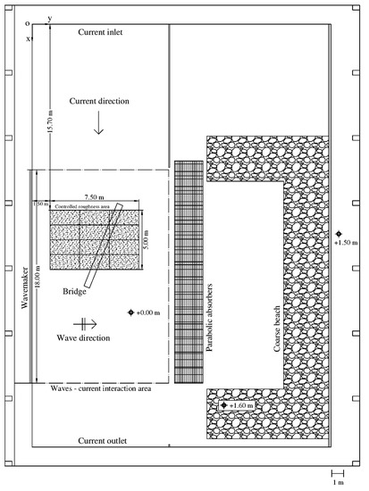
Figure 1.
Sketch of the Danish Hydraulic Institute (DHI) shallow water basin with a reference system.
In this experimental campaign an analysis of current only (CO), wave only (WO) and wave plus current (WC) condition over a ripple bed was carried out. The rippled bed was set over an area of 37.5 m2. In particular, several corrugated plastic panels were properly modeled to obtain the required ripples dimensions and were fixed through screws on 12 wood panels measuring 1.25 × 2.5 m each.
Subsequently, a homogeneous layer of glue was distributed on the panels and, through the use of a wooden model, the ripple crests were properly sharpened. Finally, the panels were sprinkled with sand with median grain size d50 = 0.9 mm, to obtain adequate surface roughness.
In Table 1 the ripple characteristics used for the realization of the bed and a cross section of the panels are illustrated.

Table 1.
Ripple characteristics.
The area of interest and, therefore, the optimal position of the instrumentation was identified by carrying out preliminary tests for one wave condition, characterized by a wave height H = 0.12 m and a wave period T = 2 s, one current condition, with mean target current velocity Uc = 0.208 m/s and one water depth (d = 0.4 m). In particular, a tracking analysis of the Lagrangian particles was performed, using neutral buoyant particles and the wave-current interaction on a large scale was monitored by visual inspection.
Finally, the velocity at 14 measuring points placed along the tank at a fixed z-coordinate was acquired in the CO condition and at 12 points in the case of WC condition at the same x and y positions (5 m < x <30 m; 3.5 m < y < 8.5 m). The main objective was to verify to what extent the local coordinates could influence the flow velocity. This procedure made it possible to identify the most suitable area where the instrumentation could be placed.
Two different absorption systems were used at the same time, the first one consists in a passive parabolic wave absorber and the second is a C-shaped beach made up of gravel of different size with a slope of 1/5.6.
Two different water depths and two wave periods were considered respectively: d = 0.4 m and 0.6 m and T = 1 and 2 s; moreover, three different wave heights (H = 0.12 m, 0.08 m and 0.05 m) propagated in the tank.
It is worth pointing out that some scale effects should be considered. Indeed, even though wave and current characteristics change, fixed ripples are considered here, in spite of their variability with the flow condition in nature. However as observed by Faraci et al. [11,12] and Petrotta et al. [13] fixed ripple dimensions can be properly chosen, based on the results of previous experimental campaigns in order to be the most statistically frequent.
Figure 2 shows a rendering of the tank, created through the use of ARCHICAD software, that displays an overview of the laboratory with the two workstations used for the experimental campaign on the two opposite sides of the tank. For the position of the instrumentation and for any other detail, please refer to the detailed sketches of the set up and the tank shown below (Figure 3).
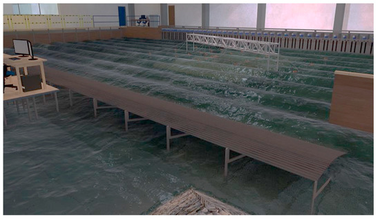
Figure 2.
Rendering of the tank through the use of the ARCHICAD software.
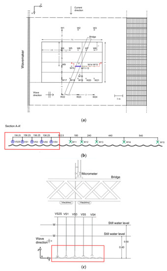
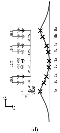
Figure 3.
Instrumentation used during the campaign. (a) Sketch of wave gauges and Vectrinos position in the tank; (b) cross section in correspondence of the Vectrinos and wave gauges used for reflection measurement at Section A-A’ (see (a)); (c) sketch of trolley with Vectrinos; (d) Vectrinos position along the ripple profile for both the configurations of the trolley.
Instrumentation
Velocity profiles were acquired by means of several high-resolution acoustic Doppler velocimeters (Vectrino Single-Point, produced by Nortek As.). More in detail, five Vectrino single-point (VS), four of them down-looking and one side-looking, were employed in the present experimental campaign. The sampling volume of the VS probe is located 50 mm far from the transducer and its dimensions can be modified via the acquisition software in relation to the desired quality of the signal; the sampling rate is up to 200 Hz.
Following the indications of van der Zanden et al. [14] and Yoon and Cox [15] the two parameters that give a measure of reliability on the measured velocities are: correlation (COR) and signal-to-noise ratio (SNR). The SNR was set greater than 20 everywhere, except near the sweet spot, i.e., between 50 and 65 mm below the transceiver, where a higher acceptance threshold SNR > 30 was considered. Instead, COR ≥ 90 was the limit adopted during all the experiments. During the analyses, data were despiked with the Goring and Nikora method [16] and the unreliable data were replaced by linear interpolations.
In the performed tests, five Vectrino single-point were positioned along the wave direction equidistant from each other, held by a trolley mounted on a bridge and vertically moved by means of a micrometer (Figure 3b,c). Moreover, two different configurations were considered by sliding the trolley by 1/8 of ripple wavelength. In this way, nine measurement positions along the ripple profile were gathered, thus obtaining more accurate information on flow field (Figure 3d).
In the following, the subscripts a and b, refer to first and second configuration of trolley, respectively as indicated in Figure 3d.
In the central part of the basin, where waves and currents interact orthogonally with each other, 24 resistive wave gauges were located allowing the free surface to be recovered (Figure 3a). Five of them, depicted in green, were placed along the same x-line but shifted along the y-axis by a fixed interval in order to measure the wave reflection inside the basin, following the method of Faraci et al. [17] as shown in Figure 3b.
3. Analysis of the Experimental Results
During the experimental campaign, 31 tests were carried out over the ripple bed. In particular, 18 tests were performed for the first position of the trolley holding the VS, 2 of them belonging to current only condition (CO), 8 to waves only (WO) and 8 to waves and currents (WC). For the second position of the trolley 13 tests were carried out, including 5 of waves only (WO), 2 of current only (CO) and 6 of waves and currents (WC), with the same wave height and period of the first series.
Figure 4a,b show, for a WO case and a WC case, respectively, a part of the signal acquired by the 5 resistive gauges (W11-W15) disposed inside the tank for the study of wave reflection (Faraci et al. [2]). By observing Figure 4a it can be noted that the signals of the gauges closest to each other (W11-W13) are almost coincident. Gauges W14 and W15 are reasonably positioned near the wave antinodes and this leads to an increase in wave height due to reflection.
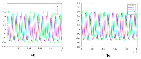
Figure 4.
Signal of 5 resistive gauges (W11–W15) for reflection study (H = 0.12 m, T = 2 s, d = 0.6 m and Uc = 0.138 m/s). (a) waves only (WO) condition; (b) waves and currents (WC) condition.
The presence of the current (Figure 4b) levels the reflection by returning a more uniform wave height trend between the gauges. According to that, by mapping the surface of the wave acquired by means of the 24 resistive gauges, located along the central part of the tank, it was possible to observe a maximum reflection at x = 18 m, along the line where W9–W15 gauges are positioned, that is equal to 20% in the WO case, while, in WC case this effect is reduced to 5%.
As already mentioned, for each test the velocity was acquired by means of several Vectrinos, which were then averaged in order to obtain a spatially representative velocity.
Figure 5 shows the velocities acquired by each Vectrino in three different cases: the CO, WO and WC conditions. In particular, Figure 5a shows the velocity in the current direction Ux, while Figure 5b shows the velocity along the wave direction Uy. In order to control the repeatability of the signal, two tests with same flow characteristics acquired in two different configurations of the trolley, were superimposed on the same figure.
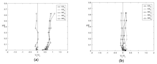
Figure 5.
Velocity profile in CO, WO and WC condition (H = 0.12 m, T = 2 s, d = 0.6 m and Uc = 0.138 m/s). The subscripts a and b for CO and WC case, refer to first and second configuration of trolley, respectively. (a)velocity profiles in current direction; (b) velocity profiles in wave direction.
WCa, for example, represents the vertical profile of the average of the 5 Vectrino measurements acquired at the 5 sections in the first position of the trolley with waves and currents (d = 0.6 m H = 0.12 m, T = 2 s and Uc = 0.138 m/s). Similarly, WCb is a test with same flow characteristics but acquired when the instruments were moved back of 1/8 of the ripple wavelength. WO case, for the second configuration of the trolley (WOb), is not present, as not all experiments were replicated.
These comparisons show that especially in the current direction there is a very good repeatability of the velocity. In the wave direction repeatability is slightly less precise but still reasonable. Indeed, maximum deviation found in the current direction is of 9% while that obtained in the wave direction is of 14%. This deviation represents the measurement error.
Furthermore, as can be seen in Figure 5b, in the wave direction, the current is not perfectly aligned on zero and, therefore, a deviation towards the beach exists that could be related to the presence of a residual steady current.
Looking at the wave only tests in x direction, the mean velocity is very small and it reverses several times up to 0.3 z/d, after which it takes negative values stably. In wave direction, the inversion occurs very close to the bed (≈ 0.1 z/d), and the undertow current takes place.
It is probable that the latter two effects, the undertow for the WO case (negative value) and the presence of a residual steady current for the CO case (positive value), cancel each other out, in such a way that the velocity profile for the WC case is almost entirely on zero.
In order to outline the variations that arise in the presence of the current on the boundary layer in the rippled bed case, studies of flow field and vorticity were carried out comparing the case of wave only and the waves plus current case.
The analysis of the flow field generating over the ripple profile was carried out by calculating the time average velocities in y and z directions.
In Figure 6, the comparison between two tests carried out with the same wave condition (H = 0.08 m T = 2 s d = 0.4 m), one in the wave only case (Figure 6a) and one with waves plus currents (Uc = 0.208 m/s) (Figure 6b) is shown. The plots show the vectorial compositions of the velocity in the y-z plan over the acquired water column, at five different vertical sections along the ripple length.
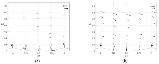
Figure 6.
Vectorial flow field over the ripples bed (H = 0.08 m, T = 2 s, d = 0.4 m and Uc = 0.208 m/s). (a) wave only condition; (b) wave plus current condition. The arrow is a reference velocity and indicates also the wave propagation direction.
In both cases, the figures clearly show the formation of recirculating cells near the bottom although the presence of current (Figure 6b) decreases the size of the cells. The size of the recirculating cells was estimated on the basis of the available vertical measurement transects, in particular, where the mean velocity reverses, and there a recirculation cell can be found. More precisely, in both cases they are formed below 0.15 z/d; in the WO case the recirculation cell extends for a width of y/λ = 0.25 and a height of z/d = 0.13 while in the WC case the recirculation cell is flatter than the previous one of 17%. Comparing the velocity profiles (Figure 5a) and the position of circulating cells (Figure 6a) that form near the bed, in the WO case the thickness of the boundary layer is identifiable up to about 0.15 z/d while in the WC case the thickness of the boundary layer is smaller and is about 0.1 z/d (see Figure 5b and Figure 6b).
Blondeaux et al. [18] with a numerical study in the presence of wave only found that the form, intensity and direction of the recirculating cell depends on three parameters, in particular ripple height (η), Reynolds number of the bottom boundary layer (Rδ) and the wavenumber of the bottom profile (k) calculated as:
with υ being the kinematic viscosity of water, δ the boundary-layer thickness and Uo the orbital wave velocity. Comparing with the present study, in similar conditions unless the Reynolds number (Rδ), the recirculation cells of Blondeaux have smaller dimensions both in terms of width and height. Such a difference probably depends on the Reynolds number, since those obtained in the present study (Rδ = 100) are about 7 times larger than those of Blondeaux (Rδ = 14.14). The rotation of the recirculation cells, instead, maintains the same trend in both studies.
Furthermore, looking at Figure 6a, from 0.2 z/d upwards, the presence of the undertow is visible and equal to 1.74 cm/s. This last value was calculated as the average velocity of the five measuring points along the ripple at the highest elevation. The undertow value found experimentally is about half of the theoretical undertow, under a flat and smooth bed condition, calculated as:
where M is the mass transport velocity given by the ratio between the wave energy and the celerity (M = E/C), the density of the water and d the water depth [19]. Such a difference probably depends on the different bed roughness, but also 2D effects due to the non-uniformity of the tank in the longshore direction could have played a role.
The presence of the current, on the other hand, as one moves away from the bottom, compensates the velocity reversal effect and, therefore, the undertow cannot be identified (Figure 6b). This result is in agreement with the velocity profile already shown (Figure 5b). Indeed, in the wave direction, in both cases it is possible to observe a positive velocity component in the beach direction correlated to the presence of a small residual current in the tank, as mentioned above.
Finally, as the knowledge of vortex structures is certainly useful to better understand the dynamics of sediment transport on a rippled bed, a vorticity study was performed on the experimental data.
Two tests with identical flow condition acquired respectively at the first and second configuration of the trolley, were selected. In this way, properly overlapping the measurements, it was possible to obtain 9 vertical measurement sections in the wave propagation direction along a single ripple for 14 elevations along the water column. In order to thicken the mesh of the acquired data, at the same elevation along the water column, the data were linearly interpolated thus calculating the vorticity on a total of 17 vertical cross sections along one ripple.
The behavior of the vortices detaching at the ripple crest at the different phases is illustrated in Figure 7 and Figure 8 for the wave only condition and the wave plus current condition, respectively.
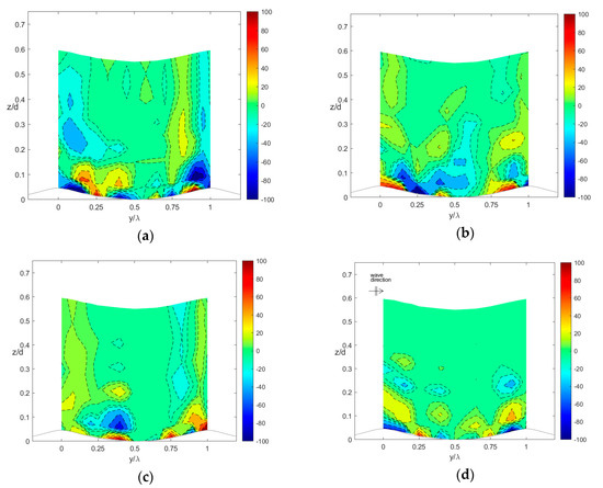
Figure 7.
Vorticity field at different phases during the wave period for wave only condition. (H = 0.12 m, T = 2 s, d = 0.4 m). (a) π/2 phase; (b) π phase; (c) 3/2π phase; (d) 2π phase.
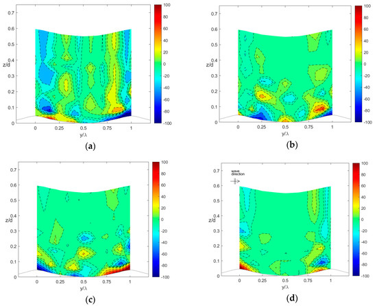
Figure 8.
Vorticity field at different phases during the wave period for wave plus current condition. (H = 0.12 m, T = 2 s, d = 0.4 m, Uc = 0.208 m/s). (a) π/2 phase; (b) π phase; (c) 3/2π phase; (d) 2π phase.
In both cases, the four figures show a filled contour plot of the vorticity made dimensionless by means of the wave period at four different phases during a wave cycle, starting with a phase of π/2 corresponding to the wave crest and with phase steps of π/2. In particular the colorbar indicates both positive and negative vorticity on the plot.
The vorticity dynamics, typical of the ripples under sea waves, varies with the variation of the phase of the wave cycle. Moreover, as known in literature, generally at the beginning clockwise vorticity is generated along the bed profile and in particular at the ripple crests. Scandura et al. [7] showed through a numerical study that within a wave the boundary layer thickens until the vortex detaches (Figure 3, Scandura et al. [7]). This result is confirmed in the present study, also from an experimental point of view. However, in the Scandura et al. [7] results, the vortex detachment is identified starting from phase 3/4 π while in the present study vortices are already identifiable at phase π/2 (Figure 7a).
In detail, at phase π/2, on the crests an anticlockwise vortex is created extending up to 0.2 z/d, while a clockwise vortex remains attached to the lee side of the ripple.
There is a correspondence between the two half cycles, as testified by the vortex separating at the ripple crest at π/2 and at 3/2π (Figure 7a,c) having approximately the same size but opposite signs. At phases π and 2π the symmetry is slightly less evident (Figure 7b,d).
Outside the boundary layer, over the ripple crests at each phase, two wide vortices are created, opposite in sign and less intense with respect to those individuated inside the boundary layer, which extend along the acquired water column. Only at phase 2π, the vorticity outside the boundary layer decreases to zero except for narrow areas close to the bed. This result finds a feedback in the theory of Sleath [20] on the motion of the sediments over ripples. In particular, for wave amplitude (a) to ripple wavelength (λ) ratios less than 1 and for high values of the viscous boundary layer thickness, two vortices opposite in sign are identified along the water column. Both these conditions are verified in the present case since a/λ = 0.2 ÷ 0.5 and Re = 11310. In agreement with Sleath [20], the two opposite vortices are clearly recognizable from phases π/2 to 3/2π being responsible for the sediment pull up that gives rise to ripple growth.
In addition, Figure 7 and Figure 8 were compared for identifying what are the effects that the superimposition of the current entail over a wave only case, both inside and outside the boundary layer. At phase π/2, the anticlockwise negative vortex on the crest for the WO case (Figure 7a) is reduced in intensity and flattened on the bed when the current is superimposed on the wave alone (Figure 8a). Furthermore, the presence of current involves a splitting of the clockwise positive vortex, formed in the WO case on the left crest, into two smaller vortices; the first one flattens on the bottom, the other one is positioned between 0.2 z/d and 0.3 z/d. Moving away from the bottom, the vorticity in the presence of current maintains the same trend, but it increases in intensity.
At phase π, the superposition of the current levels the negative vorticity on the bed. Indeed, the negative vortex that in the WO case extends longitudinally for half ripple wavelength and up to 0.3 z/d is considerably reduced in intensity and extends up to 0.15 z/d in the WC case. Looking at the right crest, a positive vortex is crushed on the bed, in the WO case (Figure 7b), while in the WC case (Figure 8b), the same positive clockwise vortex detaches, positioning itself between 0.05 z/d and 0.15 z/d with a more rounded shape. The negative vortex which is clearly identified on the crest in the WO case, lowers and extends close to the bottom in presence of current.
An opposite behavior occurs at the phase 3/2π. Indeed, the vorticity increases at the bed and decreases above 0.2 z/d. Also, the two positive and negative vortices that in the WO case extend side by side (Figure 7c), along the acquired water column, split into smaller vortices up to 0.35 z/d, as seen in Figure 8c.
The presence of the current, more or less at all phases, leads to a vorticity increase as one moves away from the bed. Indeed, observing the 2π phase, while in the WO case the vorticity is almost zero (Figure 7d), in the WC case even outside the boundary layer, we can identify higher vorticity values (Figure 8d).
In both flow conditions, focusing close to the bed, vortices detaching from the ripple crest are more or less visible, according to the phase being observed; in the WO case it is already identifiable at the phase π/2 but it becomes clearer at π. In WC, the vortex detachment is clearly seen starting at phase π, with a vortex dimension smaller than the WO case, while at the phase π/2 the identification is less immediate.
The clearly and net vortex identification occurs only in some cases probably due to the shape of the ripple profile. Indeed, Horikawa and Mizutani [10], in their comparison of flow patterns induced by sharp and round crested ripples, showed that flow separation occurs at the beginning of the half-cycle for sharp crests, earlier than it happens for round crests. They also found that the vortices shed from the sharp crests are larger and stronger than those shed from the equivalent round crests. This can be verified by comparing the results of the present study with two similar literature studies, limiting, however, the comparison to the boundary layer only (Fredsøe at al. [3] and Faraci et al. [2]). In fact, the ripple profile used in this campaign is characterized by a less sharp crest than that of Fredsøe’s study, where the detachment of large vortices can be identified more easily and at almost all the stages, even though not always sharply. The detachment the vortices observed in the present study, instead, is similar to that observed by Faraci et al. [2], since the profile of the ripples, used in the latter work is the same as this campaign. The vortices, indeed, are roughly identified at the same phases, being comparable according to dimension and sign of the vorticity.
4. Conclusions
This paper investigated the orthogonal wave current interaction over a rippled bed acquired in the framework of the WINGS campaign. The tests were carried out in current only condition, wave only condition, and wave plus current condition. The results discussed in this paper showed that:
- the superposition of the current on the wave homogenizes the wave height at all the measuring points, reducing wave reflection from 20% to 5%.
- outside the boundary layer, for the WO case, it is possible to quantify the presence of the undertow, while in the WC case the current compensates the effect of the velocity inversion, thereby making the undertow non-detectable.
- over the rippled bed, recirculating cells form in the wave propagation direction which are flattened when a current is superposed;
- the vorticity analysis revealed that a vortex detaching from the ripple crest is identifiable during a wave cycle and mainly at phases π and 2π for both WO and WC flow conditions; a symmetry in the vorticity field is noticed between the phases π/2 and 3/2π of the wave period in the WO and WC case; the presence of the current induces a decrease in the vorticity inside the boundary layer and an increase as one moves away from the bed at all phases except for the wave trough.
It is worth pointing out that in this paper, comparisons with previous experimental works were focused exclusively on the boundary layer since, to the author’s knowledge, studies of vorticity that investigate the entire water column with or without the presence of current are rather limited.
In this work, by contrast, thanks to the measurements gathered within the WINGS project we showed an example of how flow and vorticity fields change on a rippled bed when moving far away from the bottom along the water column.
A more detailed investigation taking into account all the available rippled bed data will be analysed in a forthcoming paper.
Author Contributions
Conceptualization, C.F.: and R.E.M.; Data curation, A.R.; Investigation, A.R.; Methodology, R.E.M.; Writing—original draft preparation, A.R.; Writing—review and editing, C.F.; Supervision, C.F.; funding acquisition, C.F. All authors have read and agreed to the published version of the manuscript.
Funding
The work described in this publication was supported by the European Community’s Horizon 2020 Research and Innovation Programme through the grant to HYDRALAB-PLUS (TA WINGS-Waves plus currents Interacting at a right anGle over rough bedS), Contract no. 654110.
Acknowledgments
The authors wish to thank HYDRALAB-PLUS program for funding TA WINGS-Waves plus currents Interacting at a right anGle over rough bedS, Contract no. 654110.
Conflicts of Interest
The authors declare no conflict of interest.
References
- Musumeci, R.E.; Cavallaro, L.; Foti, E.; Scandura, P.; Blondeaux, P. Waves plus currents crossing at a right angle. Experimental investigation. J. Geophys. Res. 2006, 111. [Google Scholar] [CrossRef]
- Faraci, C.; Foti, E.; Musumeci, R.E. Waves plus currents crossing at a right angle: The rippled bed case. J. Geophys. Res. 2008, 113, 1–26. [Google Scholar]
- Fredsøe, J.; Andersen, K.H.; Sumer, B.M. Wave plus current over a ripple-covered bed. Coast. Eng. 1999, 38, 177–221. [Google Scholar] [CrossRef]
- Ranasoma, K.I.M.; Sleath, J.F.A. Combined oscillatory and steady flow over ripples. J. Waterw. Port Coast. Ocean Eng. 1994, 120, 331–346. [Google Scholar] [CrossRef]
- O’Donoghue, T.; Doucette, J.S.; Van Der Werf, J.J.; Ribberink, J.S. The dimensions of sand ripples in full-scale oscillatory flows. Coast. Eng. 2006, 53, 997–1012. [Google Scholar] [CrossRef]
- Faraci, C.; Scandura, P.; Musumeci, R.; Foti, E. Waves plus currents crossing at a right angle: Near-bed velocity statistics. J. Hydraul. Res. 2018, 56, 464–481. [Google Scholar] [CrossRef]
- Scandura, P.; Vittori, G.; Blondeaux, P. Three-dimensional oscillatory flow over steep ripples. J. Fluid Mech. 2000, 412, 355–378. [Google Scholar] [CrossRef]
- Blondeaux, P.; Scandura, P.; Vittori, G. Coherent structures in an oscillatory separated flow: Numerical experiments. J. Fluid Mech. 2004, 518, 215–229. [Google Scholar] [CrossRef]
- Earnshaw, H.C.; Greated, C.A. Dynamics of ripple bed vortices. Exp. Fluids 1998, 25, 265–275. [Google Scholar] [CrossRef]
- Horikawa, H.; Mizutani, S. Oscillatory flow behaviour in the vicinity of ripple models. Coast. Eng. 1992, 1993, 2122–2135. [Google Scholar]
- Faraci, C.; Foti, E.; Marini, A.; Scandura, P. Waves plus currents crossing at a right angle: Sandpit case. J. Waterw. Port Coast. Ocean Eng. 2012, 138, 339–361. [Google Scholar] [CrossRef]
- Faraci, C.; Scandura, P.; Petrotta, C.; Foti, E. Wave-induced oscillatory flow over a sloping rippled bed. Water 2019, 11, 1618. [Google Scholar] [CrossRef]
- Petrotta, C.; Faraci, C.; Scandura, P.; Foti, E. Experimental investigation on sea ripple evolution over sloping beaches. Ocean Dyn. 2018, 68, 1221–1237. [Google Scholar] [CrossRef]
- Van der Zanden, J.; O’Donoghue, T.; Hurther, D.; Caceres, I.; McLelland, S.J.; Ribberink, J.S. Large-scale laboratory study of breaking wave hydrodynamics over a fixed bar. J. Geophys. Res. Ocean. 2017, 122, 3287–3310. [Google Scholar] [CrossRef]
- Yoon, H.-D.; Cox, D.T. Large-scale laboratory observations of wave breaking turbulence over an evolving beach. J. Geophys. Res. Ocean. 2010, 115. [Google Scholar] [CrossRef]
- Goring, D.G.; Nikora, V.I. Despiking acoustic doppler velocimeter data. J. Hydraul. Eng. 2002, 128, 117–126. [Google Scholar] [CrossRef]
- Faraci, C.; Scandura, P.; Foti, E. Reflection of sea waves by combined caissons. J. Waterw. Port Coast. Ocean Eng. 2015, 141. [Google Scholar] [CrossRef]
- Blondeaux, P.; Vittori, G. Vorticity dynamics in an oscillatory flow over a rippled bed. J. Fluid Mech. 1991, 226, 257–289. [Google Scholar] [CrossRef]
- Dean, R.G.; Dalrymple, R.A. Water Wave Mechanics for Engineers and Scientists; World Scientific Publishing Company: Singapore, 1991; Volume 2. [Google Scholar]
- Sleath, J.F.A. On Rolling-grain Ripples. J. Hydraul. Res. 1976, 14, 69–81. [Google Scholar] [CrossRef]

Publisher’s Note: MDPI stays neutral with regard to jurisdictional claims in published maps and institutional affiliations. |
© 2020 by the authors. Licensee MDPI, Basel, Switzerland. This article is an open access article distributed under the terms and conditions of the Creative Commons Attribution (CC BY) license (http://creativecommons.org/licenses/by/4.0/).