1. Introduction
Offshore wind power is a thriving renewable energy source. However, the development of offshore wind farms is costly due to the complexity of the marine environment. How to cost-effectively develop offshore wind farms has always been an important issue in the sector. In addition to the continuous innovation of offshore wind turbines, the innovation of offshore wind foundation and construction methods is also an important way to reduce costs [
1,
2]. Composite bucket foundation (CBF) is a new type of offshore wind turbine foundation proposed by Tianjin University and Daoda Company, which has a rapid construction process of structural design, onshore bulk prefabrication, integrated transportation and one-step overall installation in the appointed sea area [
3,
4,
5,
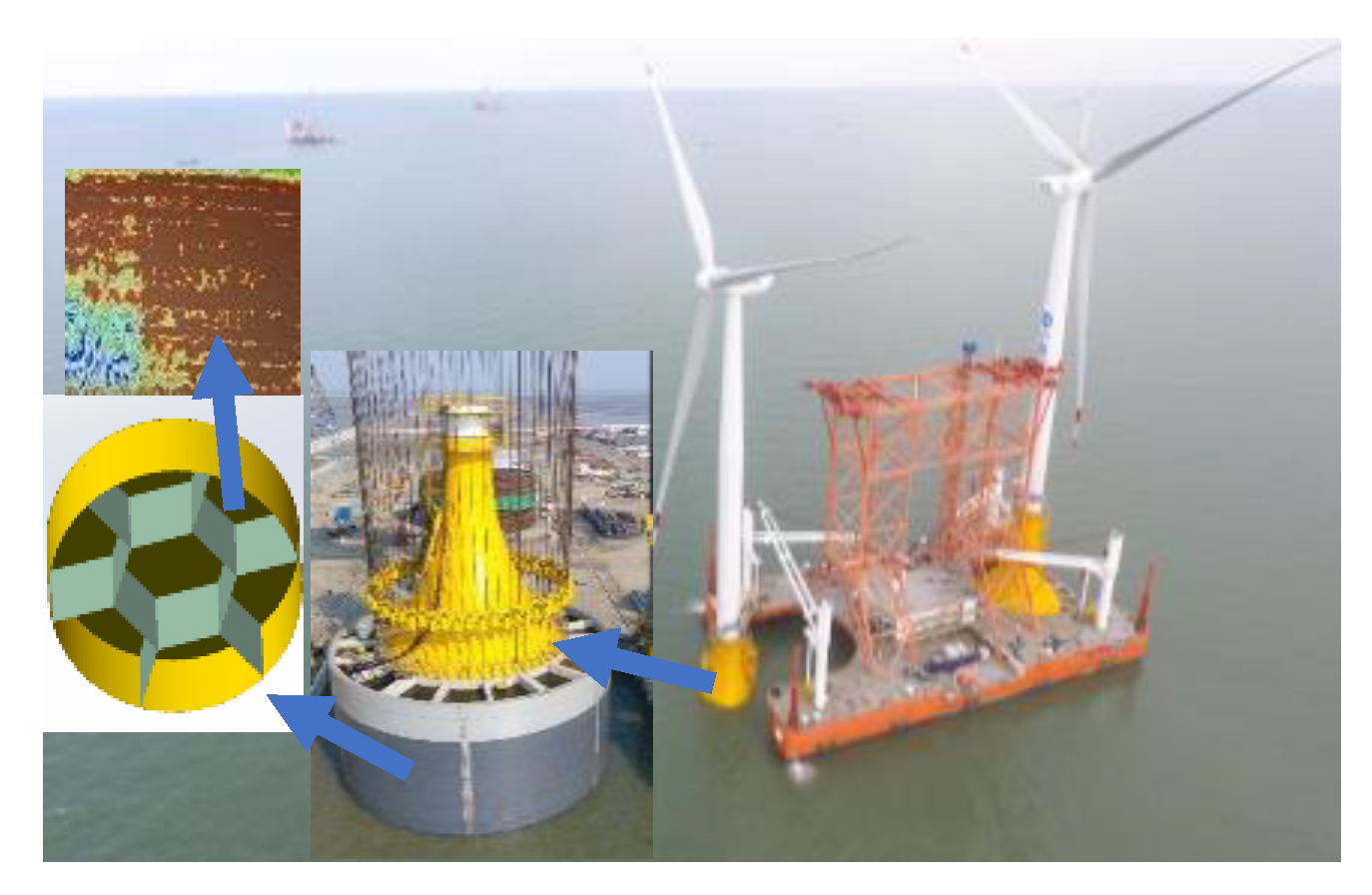
6]. It has been paid more and more attention due to its remarkable advantages of simple construction, low-cost, repeatability and excellent stability against overturn, and it can be applied in soft geological environment. It is now applied for offshore wind turbine foundations with a competitive bid price in Sanxia Dafeng offshore wind farms. After installation, vacuum preloading caused by pumping water out of seven compartments will be carried out for reinforcing soil inside composite bucket foundation and the water content will decrease obviously, as shown in
Figure 1. As a result, the consolidation settlement will be reduced in the service period and the bearing capacity of CBF will be improved.
In fact, there is a large amount of soft clay in the offshore area in China. The high compressibility and water content adversely affect the bearing capacity of the CBF. Therefore, it is necessary to find a reasonable reinforcement method to improve the bearing capacity. Vacuum preloading is an effective and environment-friendly improvement method and was first proposed by Kjellman of the Swedish Royal Geological Institute in 1952 [
7], and since then it has been used in numerous soil improvement projects worldwide. The bucket foundation is in the shape of an inverted cylinder, with a closed top and an open bottom. After the foundation is penetrated into the soil by means of suction, it is convenient to reinforce the soil inside bucket by using the vacuum preloading. Excess pore water pressure is generated and gradually dissipated. The soil is consolidated by the pore water flowing out, and the dewatering can integrate the foundation and soil into a whole part. Thus the bearing capacity and the stability of the bucket foundation are improved.
Vacuum preloading method is a proven technique, which is widely used in ports, highways, water conservation projects and other areas. In relation to the analysis of the soil reinforcement effect on the bucket foundation induced by the vacuum preloading method, it is significant to consider existing research into the traditional vacuum preloading method. Gong and Cen [
8] established a vacuum seepage field theory according to the mechanism of vacuum preloading and compared the vacuum preloading and heaped preloading and Robinson et al. [
9] carried out series of laboratory tests to study the influence of lateral deformation on volumetric strain. Peng et al. [
10] and Bao et al. [
11] conducted field tests to study pore water pressure transfer properties and distribution model of negative pressure. Shen et al. [
12] and Wu et al. [
13] proposed the calculation of consolidation settlement and increased soil strength through vacuum preloading according to the Mohr–Coulomb’s failure criterion and the vacuum preloading field test. Sun et al. [
14] proposed a membraneless vacuum preloading method and carried out a field test. The results have shown that the new method exhibits similar efficiencies to the conventional vacuum preloading method. Shen et al. [
15] put forward an air-boosted vacuum preloading method to deal with the soft ground with less reinforcement time compared with the traditional vacuum preloading method, and the effectiveness of the proposed new method verified by field tests. There is currently limited few research into the vacuum preloading technique combined with bucket foundations. Ding et al. [
16] and Lian et al. [
17] used both experimental and numerical simulation methods and a numerical simulation method to investigate the consolidation effect of the soil inside the bucket foundation by vacuum preloading. They concluded that the vacuum preloading method can effectively improve the soil strength and the bearing capacity of the foundation. Le et al. [
18], Ding et al. [
19] and Zhang et al. [
20] used vacuum pressure combined with electro-osmosis method to improve the muddy soil. The tests results showed that the electro-osmotic method can accelerate the consolidation compared with the single vacuum preloading method and the strength of the muddy soil can be improved significantly by combining the two methods.
The previous studies just consider the bucket foundation without the bulkheads and do not provide any relevant analysis of composite bucket foundations. In addition, they have not considered the influence of bulkheads on the reinforcement effect produced by vacuum preloading. Moreover, the settlement and the void ratio of soil inside the bucket foundation at different height were not analyzed. Hence this paper investigates the reinforcement effect of both foundations as well as the influence of bulkheads, through a three-dimensional numerical model using the finite element software ABAQUS. This simulates the consolidation process of soil under vacuum pressure. The results demonstrate a number of key parameters, which are essential to the evaluation of effectiveness of vacuum preloading, including the vertical settlement as well as the changes in pore water pressure and void ratio of the reinforced soil for both types of bucket foundation.
2. Finite Element Model
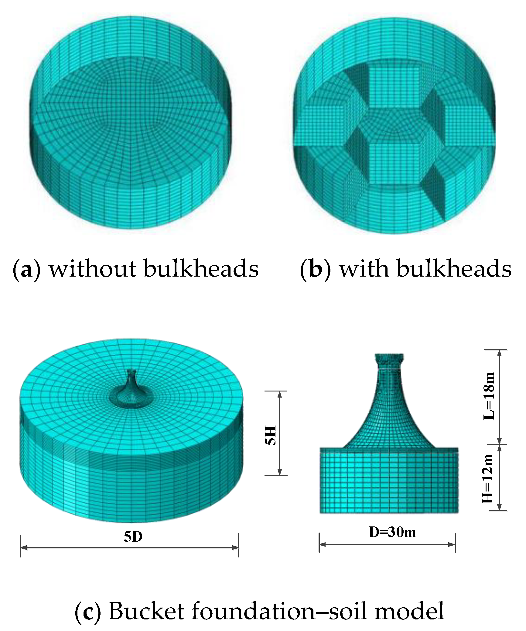
In order to obtain a clear indication of the improvement effect of the vacuum preloading method, a three-dimensional finite element model of the bucket foundations with and without bulkheads is established using the universal finite element analysis software ABAQUS, as shown in
Figure 2. The seven rooms are defined inside the bucket by the bulkheads. The six peripheral rooms have the same proportions, while the middle room is slightly larger. The three-dimensional model for the bucket foundation and the soil is shown in
Figure 2c. The model parameters refer to the installed bucket foundation. The arc transition section is made of prestressed concrete with a length (L) of 18 m. The bucket in the simulation has an outer diameter (D) of 30 m and a clear wall height (H) of 12 m, with 0.015 m in thickness. The bucket is simulated by shell elements for the analysis. The middle room of the bucket foundation with bulkheads is hexagonal and the thickness is 0.1 m. To eliminate the boundary effect of the soil, the diameter is 5D and the height is 5H.
It is assumed that the initial void ratio of soil is constant with depth in the calculation. The soil is assumed to be homogeneous silty clay and the parameters are listed in
Table 1. The simulation is about porous medium seepage and follows Darcy’s law and the Biot consolidation theory. The Modified Cam Clay model is used to model the behaviour of the soil.
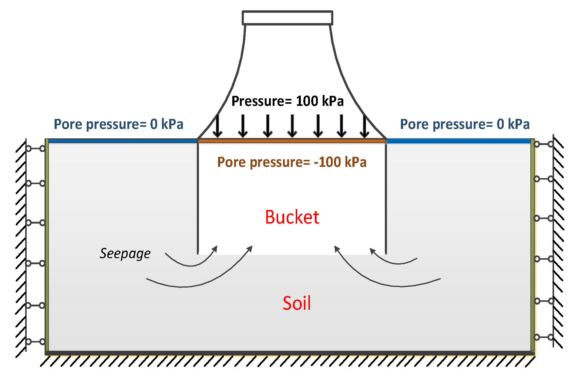
The step of soils is established after balancing the ground stress. Though the suction can be created theoretically as 200 kPa with 10 m water depth, considering soil profile, water gradient loss and pump capacity, the difference of water head applied in real engineering was just approximately 10 m. So the boundary conditions of the pore water pressure at the surface soil inside and outside the foundation are set as 100 kPa and 0 kPa respectively, which mean the underpressure of the top lid is 10 m water head and initial pore water pressure is −100 kPa inside the bucket. It uses the difference of water pressure to impose the load on the soil, resulting in excessive pore water pressure. As the pore water is extracted from the top of the bucket, the excessive pore water pressure turns into soil effective stress due to dewatering, so the soil is reinforced. Horizontal displacement is prevented at the side boundaries of the soil, and at the bottom boundary, the vertical, horizontal and rotational displacements are all fixed. The contact pair algorithm in the ABAQUS is employed to simulate the contact features of the interface between the foundation and the soil, with a friction coefficient of 0.5. This takes a total of twenty days. The load and boundary conditions of the finite element model are illustrated in
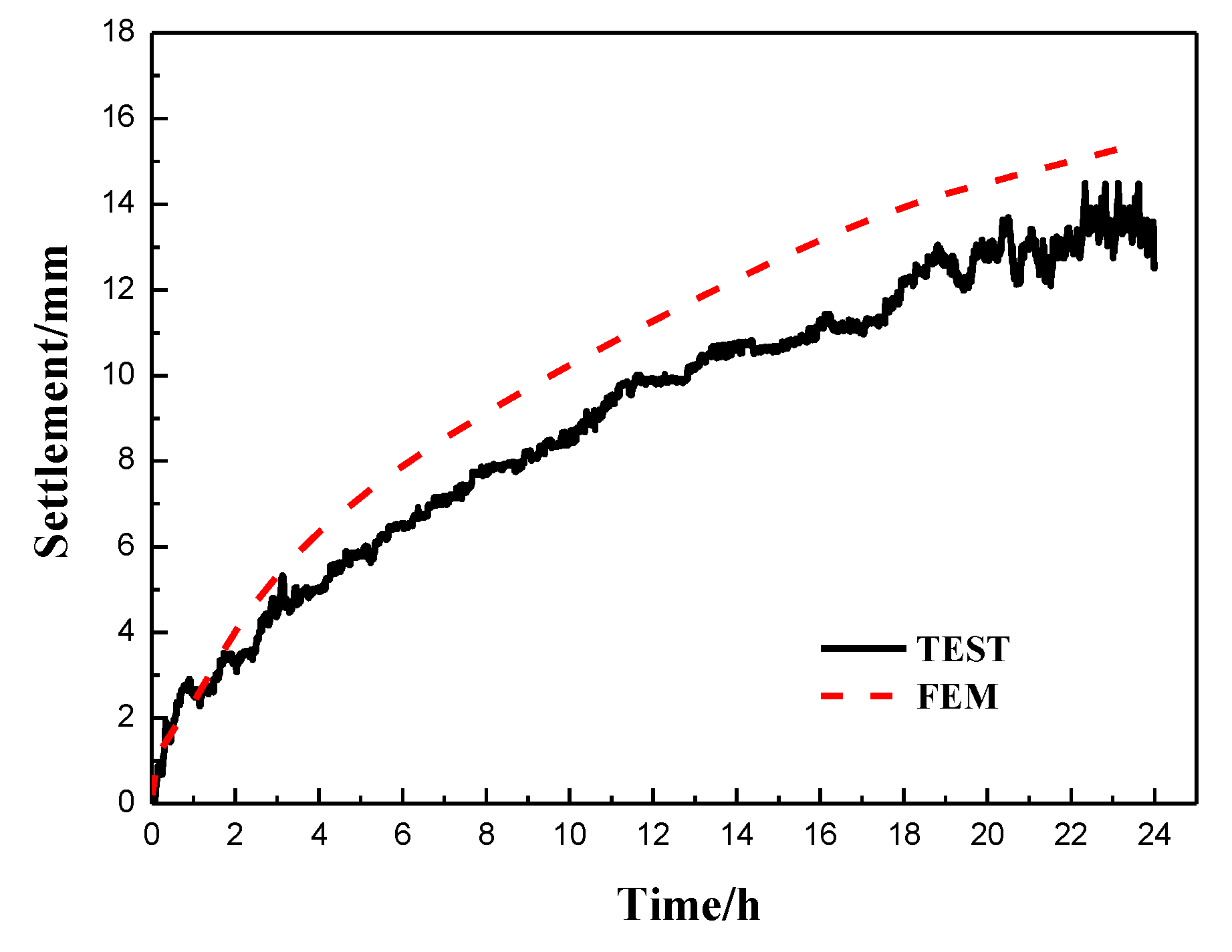
Figure 3. Before this study, numerical simulation was performed using ABAQUS to confirm the reliability of finite element method (FEM) results with 1:100 experimental test data under a water head of 6 m at the top lid [
21], as illustrated in
Figure 4.
3. Analysis of the Consolidation Effect of the Soil
The degree of consolidation induced by vacuum loading can be expressed by the variation of vertical settlement, pore water pressure and void ratio of the soil. Therefore, the results of the finite element analysis are summarized focusing on these aspects in the following sections.
3.1. Vertical Settlement
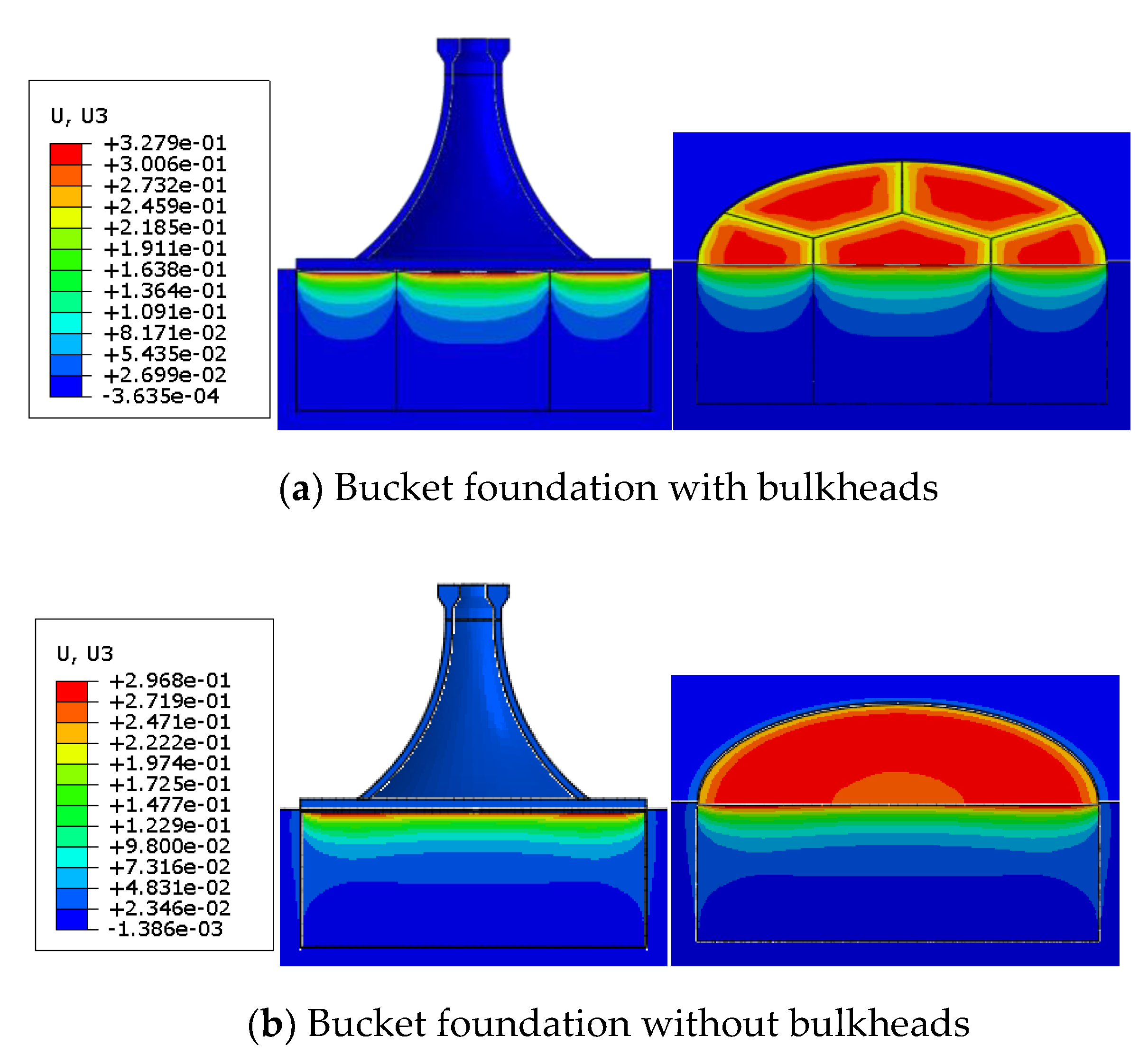
The vertical settlement nephograms of reinforced soil are shown in
Figure 3a,b, where the maximal values are 32.79 cm and 29.68 cm, respectively, at the surface soil in the reinforced area. Comparisons of the vertical settlement curves changing with time at different positions are shown in
Figure 5, selecting three different surface positions inside and outside the bucket for the two foundations, respectively. A1, B1 and C1 are the centre points of the middle room, side room and a surface point that is 5 m outside the bucket foundation with bulkheads. A2, B2 and C2 are the points in the same position for the foundation without bulkheads. It can clearly be observed that the soil settlement inside the foundation increases rapidly by vacuum load and the settlements account for 90% of the total value on the first ten days. The settlement of B1 is larger than other points, and the settlement rate of B1, A1, and A2 are 2.75 cm, 2.70 cm and 2.28 cm per day, respectively. The increase in vertical settlement begins to slow down over the next ten days and the daily settlement reduces to 0.53 cm, 0.25 cm and 0.35 cm, respectively. C1 and C2 both increase slowly and linearly with a stable rate of only 0.06 cm and 0.08 cm per day during the whole process and ultimately to a value of less than 3 cm.
The above phenomena can be explained as follows. There is a pressure difference between the soil inside the bucket and the surroundings, which leads to a stable seepage channel in the soil. With pore water being extracted out of the bucket, the soil settles fast at first and the consolidation effect is obvious. In later stages, the void ratio and the permeability coefficient decrease due to the constant consolidation of the soil, leading to a slower rate. Vacuum pressure causes an incremental isotropic consolidation stress on the soil elements, and it also induces soil shrinkage deformation. The composite bucket foundation can be divided into separate reinforced areas after adding the bulkheads. Thus, in each room, the soil moves horizontally towards the center and contributes to vertical drainage channels around the bulkheads. As a result, the soil settlement in the bucket foundation with bulkheads is larger than that without bulkheads. In addition, the area of the side room is less than that of the middle room, thereby shortening the seepage path, and this contributes to the increased drainage of pore water over the same consolidation time. This is why the maximum settlement is seen at point B1. The bucket wall prevents the vacuum pressure from transmitting outwards and hence the vacuum pressure mainly affects the soil inside the foundation. The settlement of the soil outside the bucket is not directly affected by vacuum pumping, but it is caused by the cohesive force of the soil when the foundation settles.
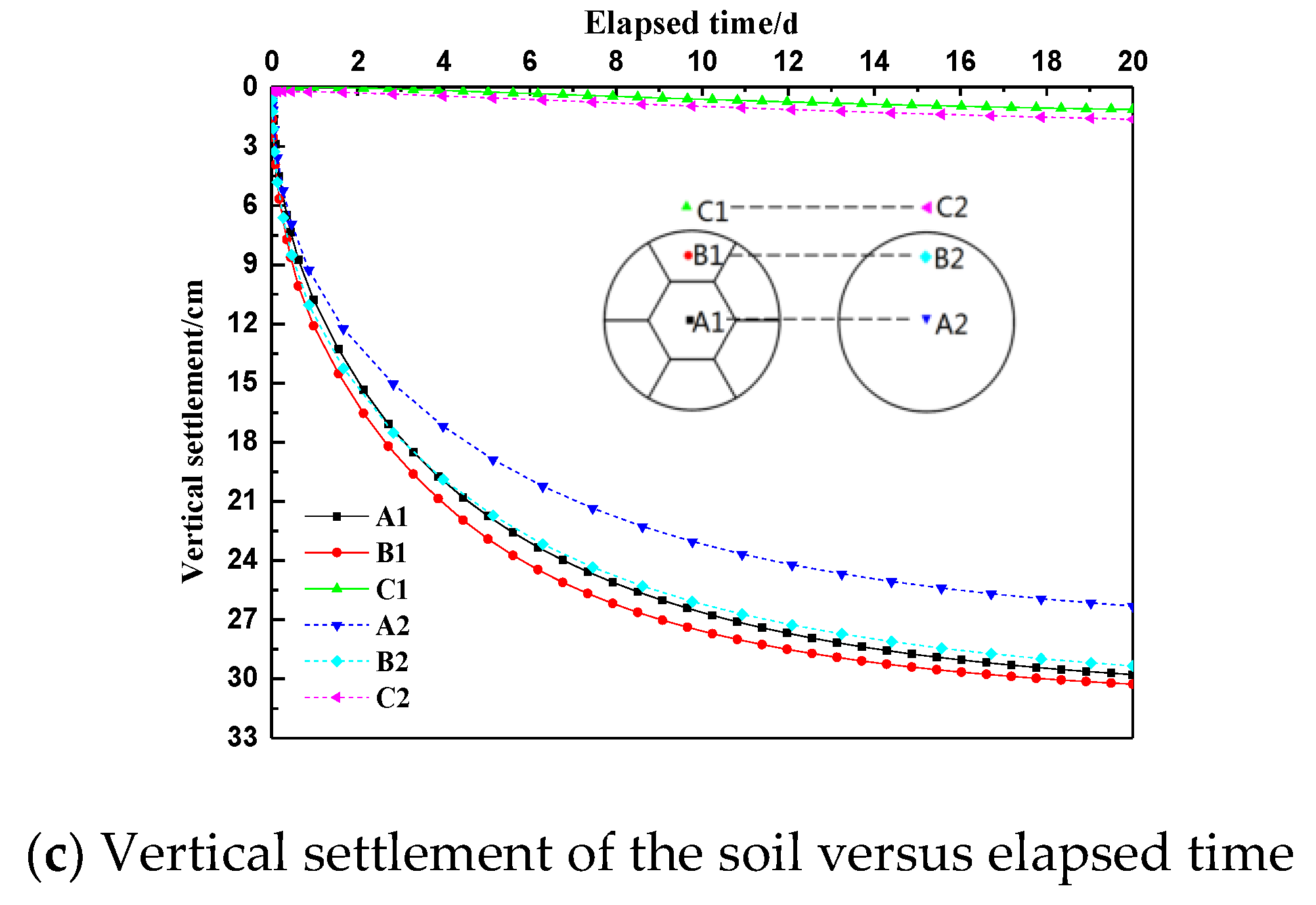
Figure 6 shows the vertical settlements with distance from the centre at different depths. The curves of the bucket foundation without bulkheads are more gentle and uniform. Below the depth of 0.6 H, the settlement of the soil is less than 3 cm and there is little settlement at the depth of H. It indicates that the vacuum pressure has little effect on the soil below the depth of 0.6 H. Furthermore, the soil settlement inside the bucket foundation with bulkheads is 3 cm larger than that without bulkheads within 0.6 H depth. Each room in the foundation with bulkheads can be considered as an independent section. The settlement increases first and then decreases from the centre to the edge in the reinforced area. The minimum value occurs near the bulkheads. Due to the shrinkage of the soil induced by vacuum preloading, the central soil is the densest and the void ratio is the lowest. From the centre to the edge of the reinforced area, the soil gradually approaches the vertical drainage channels around the bucket wall and the bulkheads. Consequently, settlement increases as seepage path decreases. The adhesion and friction between bucket walls and the soil hinders the settlement and the value decreases.
Figure 7 shows a plot of the vertical settlements with soil depth along different paths, which are located at the centre of the middle room and the side room of the foundation with bulkheads and the centre of the foundation without bulkheads. Overall, the settlement distributions for different paths show a similar tendency. It is estimated that within 0.6 H depth, there is most vertical settlement and this accounts for about 85% of the total value. The soil within one metre from the surface settles ~40%, and at a range between one to two metres this reduces to ~20%. Furthermore, the proportion of the settlement decreases to 10% at a depth between two to three metres. The vertical settlement in unit depth decreases with increasing depth. In the case of the bucket foundation with bulkheads the settlement of the soil above 0.6 H is higher, while the contrary is observed for soil below 0.6 H. This is expected as the bulkheads provide more vertical drainage channels in the soil, and shorten the seepage path. As the consolidation time increases, the void ratio of the shallow soil gradually reduces and the soil becomes denser. This has a reduced effect on the drainage rate and reinforcement effect for deep soil.
3.2. Pore Water Pressure
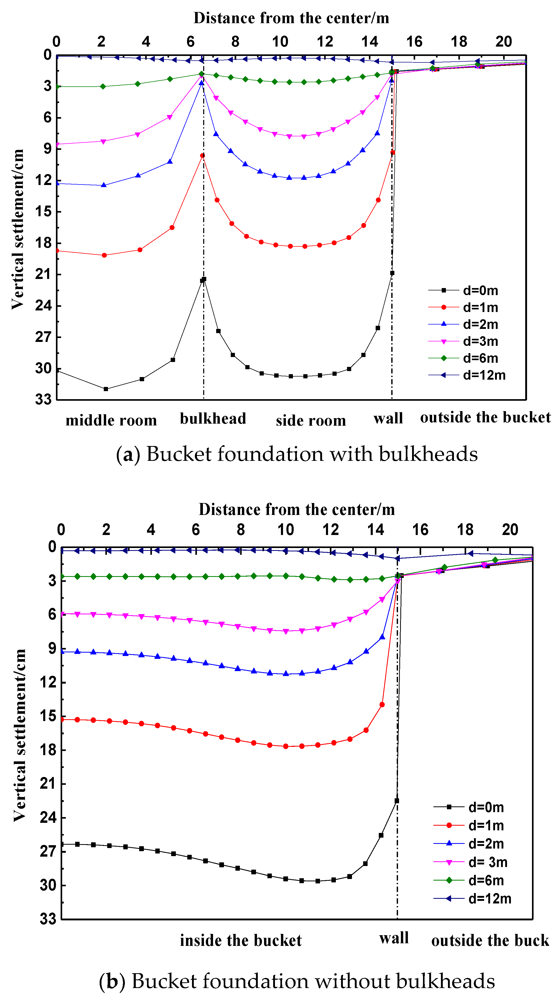
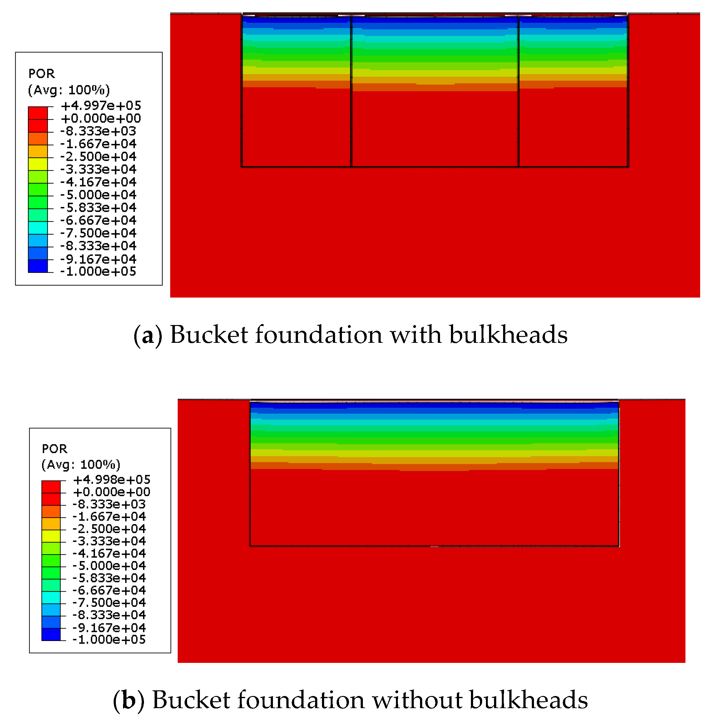
The pore water pressure nephograms of the reinforced soil are shown in
Figure 8. The figures reveal that there is little difference on the resulting distribution of pore water pressure compared with the two foundation types. The depth of negative pore water pressure occurs within 0.6h, which is consistent with the depth vertical settlements, and the reinforcement area is expressed by the region with negative pore water pressure.
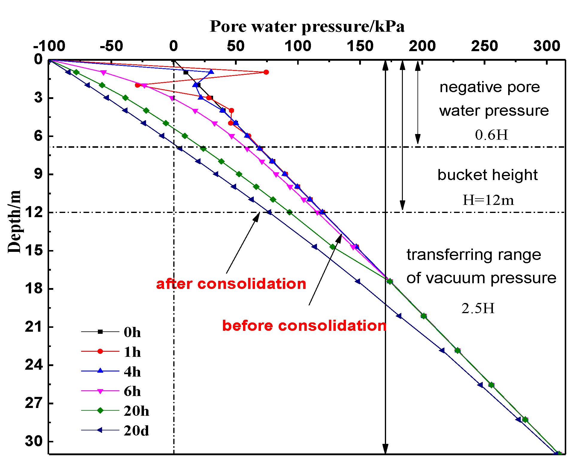
The variation of pore water pressure with depth at different times for bucket foundation with bulkheads is shown in
Figure 9. In the first few hours, the soil shows the Mandel effect as the pore water pressure rises and exceeds the initial value, so the curve fluctuates locally. The pore water pressure changes regularly and decreases steadily with time passes after 6-h reinforcement. It is clearly observed that the decrease in pore water pressure slows with the increase both of the time and the soil depth. This indicates that the vacuum pressure decreases over the diffusion process: the greater the time and the soil depth, the greater the loss. The final pore water pressure tends towards stability with the continuous consolidation of the soil. When comparing the pore water pressure curve before and after consolidation, it can be concluded that the vacuum pressure diffuses to considerable depth and it is up to a depth of 2.5 h that the pore water pressure changes to varying degrees. The change in pore water pressure decreases with increase in soil depth. The pore water is pumped out and the excess pore water pressure dissipates, so the pressure borne by the pore water is gradually transferred to the soil skeleton leading to an increase in the soil effective stress. The difference between the pore water pressure before and after the consolidation is the added value of the soil effective stress. Therefore, the dissipation process of the excess pore water pressure essentially reflects the reinforcement process of the soil.
3.3. Void Ratio
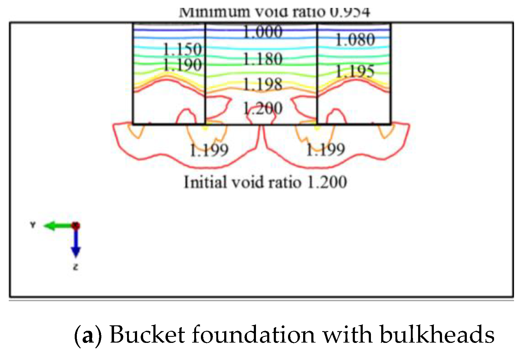
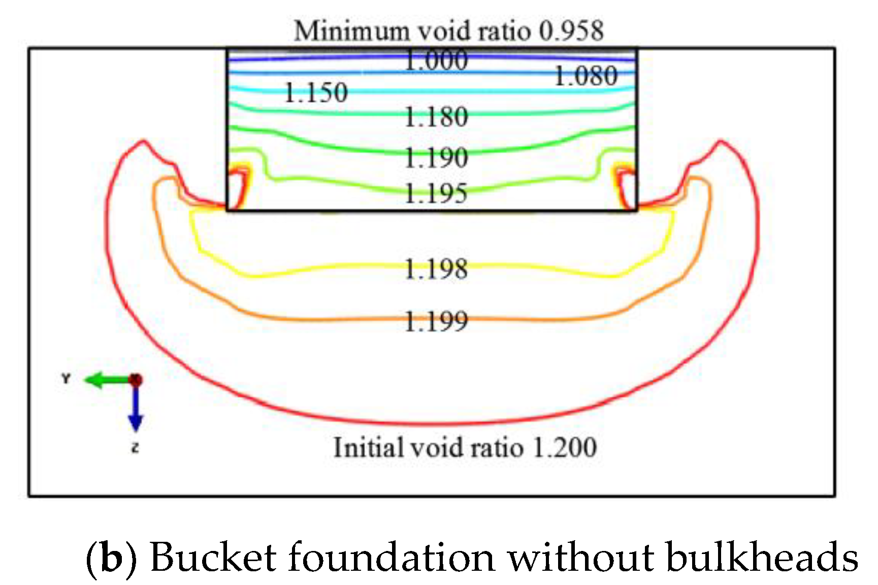
The void ratio contour maps of the reinforced soil are illustrated in
Figure 10, where the minimum value for both types of bucket foundations drops from the initial void ratio of 1.200 to 0.954 and 0.958. These minimum values are located in the surface reinforced region. The values indicated in
Figure 10 show that in shallow soil, the change in void ratio is more and the reinforcement effect is higher for the foundation with bulkheads, while opposite happens in deep soil.
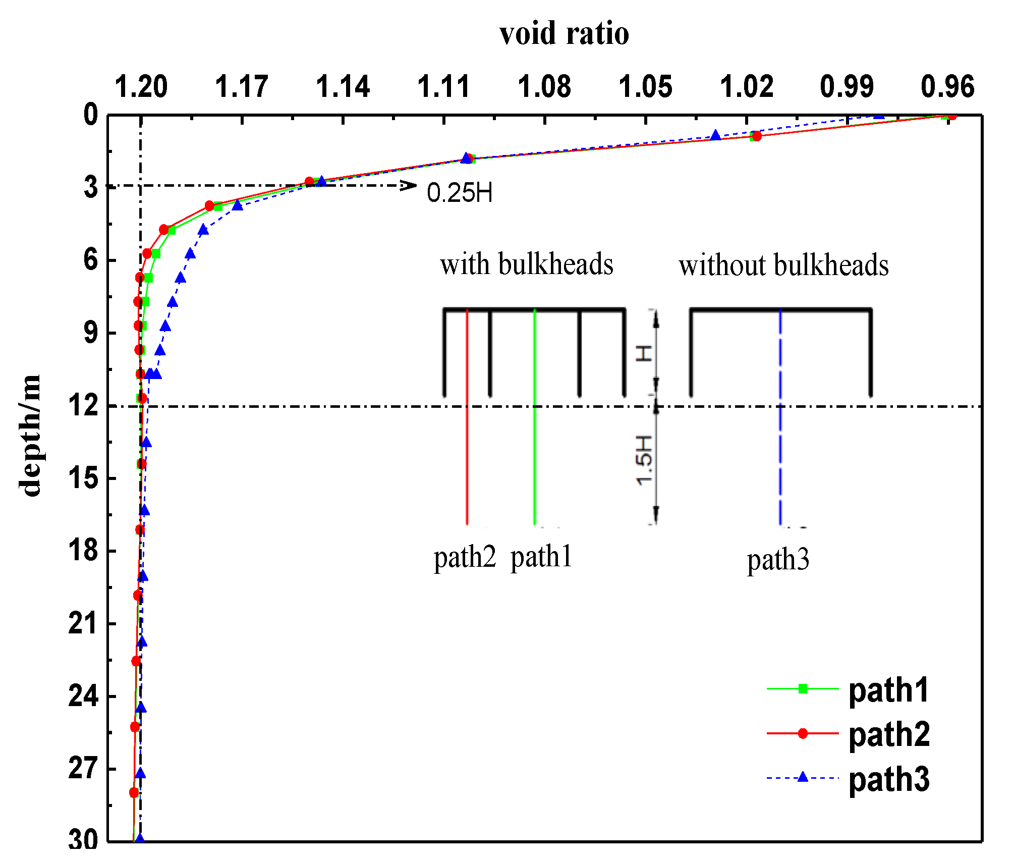
Figure 11 shows the change in void ratio with soil depth along different paths, which are located at the centre of the middle room and the side room of the foundation with bulkheads and the centre of the foundation without bulkheads. The figure shows that the variation in void ratio decreases with the increase in depth. The void ratios of the soil above 0.25 h for the two foundations show small differences. In the case of the soil below 0.25 h, the void ratio for the foundation without bulkheads is lower; this indicates that more pore water can be extracted from the bucket. The result is consistent with the change in vertical settlement: the larger density of the soil inside the foundation leads to the lower permeability, which decreases the vacuum pressure transfer. Therefore the region of the soil without bulkheads that can be reinforced under vacuum pressure is larger than that with bulkheads. In summary, the bulkheads provide additional vertical drainage channels in the soil and better consolidation can be achieved in the shallow soil, while better consolidation soil decreasing the seepage rate and the region of the soil that can be reinforced.
4. Conclusions
This paper presents the simulations of the consolidation process of soil inside the foundations employed by vacuum preloading method in clay. Based on the results of the two kinds of bucket foundation numerical model, the following conclusions can be drawn:
(1) After the consolidation of vacuum preloading method, there are obvious soil vertical settlements for both foundation types, with the foundation with bulkheads settlings more. In the first 10 days, the settlement of surface soil is higher, accounting for 90% of the total settlement; this becomes more stable during the latter 10 days. The settlement increases first and then decreases from the centre to the edges in each reinforced area, with the minimum values at the edges. The depth where most vertical settlement is observed is 0.6 H, and this accounts for approximately 85% of the total value.
(2) Pore water pressure of the soil for both foundation types has the same distribution with depth after consolidation. The depth where the pore water pressure becomes negative is about 0.6 H, which also is the main reinforcement depth. The vacuum pressure decreases continuously with time and soil depth, and eventually the pore water pressure becomes stable. The difference between pore water pressure before and after the consolidation is the added value of the effective stress of the soil. Therefore the dissipation process of excess pore water pressure essentially reflects the reinforcement process of the soil.
(3) The variations of the soil void ratio decrease with increase in depth. In shallow soil, the void ratio for the bucket foundation with bulkheads decreases more and the consolidation effect is better than that in deep soil. In the foundation without bulkheads, there is a larger region of soil depth that shows improvement effect.
(4) The pore water pressure of the foundation with the bulkheads is higher than that without the subdivision at the same level and therefore the bulkheads contributes to the transfer of pore water pressure. This is conducive to the improvement of shallow soil. Along with the increase in consolidation time, pore water in shallow soil is extracted from the foundation, gradually decreasing the void ratio and increasing the soil density. The seepage channels in deeper soil are more restricted, with a reduced drainage rate and reinforcement effect.
Author Contributions
Conceptualization, H.D. and P.Z.; methodology, H.D. and P.Z.; validation, Y.P. L.N. and H.Z.; software, Y.P. L.N.; formal analysis, L.N. H.Z. Y.P.; writing—original draft preparation, L.N. and H.Z.; writing—review and editing, Y.P. P.Z.; funding acquisition, H.D. and P.Z.
Funding
This research was funded by National Natural Science Foundation of China (Grant Nos. 51779171&51679163), Innovation Method Fund of China (Grant No. 2016IM030100) and the Tianjin Municipal Natural Science Foundation (Grant No. 17JCYBJC22000).
Conflicts of Interest
The authors declare no conflict of interest.
References
- Rasuo, B.; Bengin, A. Optimization of Wind Farm Layout. FME Trans. 2010, 38, 539–540. [Google Scholar]
- Rasuo, B.; Dinulovic, M.; Veg, A.; Grbovic, A.B. Harmonization of new wind turbine rotor blades development process: A review. Renew. Sustain. Energy Rev. 2014, 39, 874–882. [Google Scholar] [CrossRef]
- Ding, H.; Lian, J.; Li, A.; Zhang, P.Y. One-step-installation of offshore wind turbine on large-scale bucket-top-bearing bucket foundation. Trans. Tianjin Univ. 2013, 19, 188–194. [Google Scholar] [CrossRef]
- Zhang, P.; Ding, H.; Le, C.; Huang, X. Motion analysis on integrated transportation technique for offshore wind turbines. J. Renew. Sustain. 2013, 5, 053117. [Google Scholar] [CrossRef]
- Ding, H.; Liu, Y.; Zhang, P.; Le, C.H. Model tests on the bearing capacity of wide-shallow composite bucket foundations for offshore wind turbines in clay. Ocean. Eng. 2015, 103, 114–122. [Google Scholar] [CrossRef]
- Zhang, P.; Han, Y.; Ding, H.; Zhang, S.Y. Field experiments on wet tows of an integrated transportation and installation vessel with two bucket foundations for offshore wind turbines. Ocean Eng. 2015, 108, 769–777. [Google Scholar] [CrossRef]
- Kjellman, W. Consolidation of clay soil by means of atmospheric pressure. In Proceedings of the a Conference on Soil Stabilization, Massachusetts Institute of Technology, Boston, MA, USA, 18–20 June 1952; pp. 258–263. [Google Scholar]
- Gong, X.; Cen, Y. Mechanism of vacuum preloading. J. Harbin Univ. CE Archit. 2002, 35, 7–10. [Google Scholar]
- Robinson, R.; Indraratna, B.; Rujikiatkamjorn, C. Final state of soils under vacuum preloading. Can. Geotech. J. 2012, 49, 729–739. [Google Scholar] [CrossRef]
- Peng, J.; Ji, W.; Li, N.; Jin, H.R. The pore water pressure and settlement characteristics of soil improved by combined vacuum and surcharge preloading. Electron. J. Geotech. Eng. 2013, 18, 155–158. [Google Scholar]
- Bao, S.; Mo, H.; Dong, Z.; Chen, P. Research on transfer properties and distribution model of negative pressure in fresh hydraulic reclamation muck foundation. Rock Soil Mech. 2014, 35, 3570–3576. [Google Scholar]
- Shen, Y.; Huang, W.; Li, Y. Calculation method of bearing capacity improvement of soft soil foundation under vacuum preloading. Appl. Mech. Mater. 2013, 353–356, 352–356. [Google Scholar] [CrossRef]
- Wu, Y.; Xu, F.; Yuan, M.; Sun, D.A. Ground deformation induced by vacuum loading–unloading. Environ. Earth Sci. 2016, 75, 1–8. [Google Scholar] [CrossRef]
- Sun, L.; Guo, W.; Chu, J.; Nie, W. A pilot test on a membraneless vacuum preloading method. Geotext. Geomembr. 2017, 45, 142–148. [Google Scholar] [CrossRef]
- Shen, Y.; Wang, H.; Tian, Y. A new approach to improve soft ground in a railway station applying air-boosted vacuum preloading. Geotech. Test. J. 2015, 38, 20140106. [Google Scholar] [CrossRef]
- Ding, H.; Liu, Y.; Zhang, P. Negative pressure consolidation of silt inside bucket foundation. Trans. Tianjin Univ. 2015, 21, 333–340. [Google Scholar] [CrossRef]
- Lian, J.; Wu, M.; Zhang, J.; Wang, H. Study on influences from soil reinforcement on bearing characteristics of bucket foundation. Water Resour. Hydropower Eng. 2015, 46, 50–55. [Google Scholar]
- Le, C.; Ding, H.; Zhang, P. Experimental study of muddy soil inside bucket foundation using vacuum electro-osmotic reinforcement. J. Dalian Univ. Technol. 2013, 53, 97–101. [Google Scholar]
- Ding, H.; Li, Z.; Lian, J.; Zhang, P.Y. Soil reinforcement experiment inside large-scale bucket foundation in muddy soil. Trans. Tianjin Univ. 2012, 18, 168–172. [Google Scholar] [CrossRef]
- Zhang, P.; Ding, H.; Zhai, S.; Xiong, K.P. Test on muddy soil reinforcement by negative pressure and electro-osmosis inside over-bearing-type bucket foundation for offshore wind turbines. Trans. Tianjin Univ. 2013, 19, 010–016. [Google Scholar] [CrossRef]
- Nie, L. Study on the negative pressure and electro-osmosis consolidation method for internal soil of bucket foundation for offshore wind turbines. Trans. Tianjin Univ. 2017, 21, 333–340. [Google Scholar]
© 2019 by the authors. Licensee MDPI, Basel, Switzerland. This article is an open access article distributed under the terms and conditions of the Creative Commons Attribution (CC BY) license (http://creativecommons.org/licenses/by/4.0/).


