Article

A Numerical Investigation on the Flooding Process of Multiple Compartments Based on the Volume of Fluid Method

1
College of Shipbuilding Engineering, Harbin Engineering University, Harbin 150001, China
2
Department of Industrial Engineering, University of Naples “Federico II”, 80125 Naples, Italy
*
Author to whom correspondence should be addressed.
J. Mar. Sci. Eng. 2019, 7(7), 211; https://doi.org/10.3390/jmse7070211
Submission received: 14 June 2019 / Revised: 7 July 2019 / Accepted: 8 July 2019 / Published: 10 July 2019
(This article belongs to the Section Ocean Engineering)

Abstract

:
A detailed description of the flooding process is crucial to analyze the complex hydrodynamic behaviors and enhance the survivability of the damaged ship. In this paper, through establishing three typical damage scenarios with various locations, the commercial software CD Adapco STAR-CCM+ based on the Reynolds-Averaged Navier-Stokes (RANS) solver is applied to simulate the flooding process involving multiple compartments. The basic computational fluid dynamics (CFD) models and specific simulation settings are elaborated. The volume of fluid (VOF) method combined with the user defined field function is developed to distribute the initial free surface. The captured flooding process indicates that the air compression due to the restricted ventilation decreases the flooding amount. The obtained flooding time can provide necessary data to support for appropriate rescue management and evacuation options.

1. Introduction

In the last decades, a large number of ship accidents continue to occur regardless of how a ship is designed, constructed and operated. When the ship is damaged, the motion of fluid into the flooded compartments is violent and complex. Generally, the flooding process can be mainly divided into three phases: The transient stage, the progressive stage, and the steady stage. In the first stage, the high hydrostatic pressure across the damaged opening drives the external water to flood into the empty compartment drastically [1]. The complex dynamics and fluid-structure interaction has a strong effect on the stability of the ship, making the ship sink rapidly or even capsize. However, this stage lasts only a couple of roll cycles and is referred to as the transient stage, according to IMO SLF46/INF.3 (2003) [2]. After this stage, the progressing flooding tends to be quasi-stationary and flows through internal openings to other compartments. Eventually, if the damaged ship can keep afloat, a steady equilibrium is reached [3]. In an effort to increase ship survivability and reduce the risk to human life from flooding, a clear understanding of the water flooding process is essential to establish proper life-saving measures and evacuation procedures [4]. The hydrodynamic problem in the flooding process has been a major issue as summarized in the last several International Towing Tank Conference (ITTC) Stability in Waves Committee Reports [5,6].
The complex dynamics problem has been elaborated by performing model tests and numerical simulation. Rodrigues et al. [7] implemented an experimental procedure to measure progressive flooding on a small-scale damaged floating body. The measurements of the water levels at each flooded compartment are continuously made by pressure sensors fitted in the model. Ruponen, et al. [8] analyzed the delaying effect of air compression on the flooding process through systematic full-scale tests with a decommissioned ship. Water heights under various ventilation conditions were measured with pressure gauges at specified points. Lee, et al. [9] performed well-designed model tests with a flooding water behavior measurement system to capture the free surface of the flooding water. The experimental data obtained is valuable for CFD validation and development. Manderbacka [10] tracked water surface in flooded compartments with an experimental model of a box-shaped barge. The wave probes and video camera were utilized to estimate the water height and flooding process. Although these model experiments can accurately measure the water heights and capture the free surface in the specified damaged scenario, a model test cannot tackle multiple damage cases efficiently and economically.
During the past two decades, owing to the improvements in high-performance computers, application of CFD methods may be a viable alternative approach. A fundamental, but more sophisticated, time-domain simulation method of investigating the damage flooding has been developed in the European Commission Seventh Framework (EU FP7), FLOODSTAND. The developed approach monitors the flooding process and assesses the size of the breach based on the level sensor data with reasonable accuracy [11]. Sadat-Hosseini, et al. [12] assessed the Unsteady Reynolds Averaged Navier-Stokes (URANS) capabilities for ship flooding and motion response by using experimental validation data. Skaar, et al. [13] used a novel technique where fluid particle motions were calculated individually from a Lagrangian perspective-smoothed particle hydrodynamics (SPH). The flooding of a 2D section of a Ro-Ro ship in forced heave and roll motions was modelled. XinLong, et al. [14] focused on the application of commercial software STAR-CCM+ Reynolds-Averaged Navier-Stokes (RANS) solver for analyzing the effect of air compression on the flooding process. Cao, et al. [15] proposed a multi-phase SPH model combined with a dummy boundary method, considering air effect on the responses of the damaged ship in the dynamic flooding process. In order to highlight the effect of air flow in modeling the behavior of the vessel, model experiments and simulations have been performed in calm water and in waves of different heights and periods [16]. In addition, a numerical non-linear time domain simulation based on the lumped mass method was applied to investigate the flooding process and transient response of a ship to abrupt flooding [17]. Recently, Acanfora et al. [18] developed a fast simulation approach which was able to simulate both the transient stage of flooding and the dynamic behavior of a flooded ship in regular waves. These numerical simulation methods have been proven to provide convenience and reliability for flooding researches.
In this paper, the numerical simulation based on the RANS solver with the surface processing techniques (VOF) has been applied to capture the air-water interface. The user defined field function (UDFF) was developed to define the initial distribution of free surface. The overall aim of the study is to simulate the flooding process, obtain the flooding sequence and flooding time, and eventually provide data support for damage management and evacuation option. The simulated programs were based on the commercial CFD package STAR-CCM+ 12.02 and done on a workstation with 12-processors (3.20 GHz).

2. Methodology

2.1. Realizable k- ε Turbulence Model

Turbulence is a state of fluid motion characterized by apparent random and chaotic three-dimensional vorticity. The k- ε turbulence is a two-equation model in which transport equations are solved for the turbulent kinetic k and its dissipation rate ε [19]. The specified equations are described as follows.
d d t V ρ k d V + A ρ k ( v v g ) d α = A ( μ + μ t σ k ) k d α + V [ f c G k + G b ρ ( ( ε ε 0 ) + γ M ) + S k ] d V  
d d t V ρ ε d V + A ρ ε ( v v g ) d α   = A ( μ + μ t σ ε ) ε d α + V [ f c C ε 1 S ε + ε k ( C ε 1 · C ε 3 · G b ) ε k + v ε C ϵ 2 ρ ( ε ε 0 + S ε ) ] d V
where ρ is the density; v is the velocity vector; v g is the velocity vector parallel to g; μ is the laminar viscosity; μ t is the turbulent viscosity; f c is the curvature correction factor; G k is the turbulent production term; G b is the buoyancy production term; ε 0 is the ambient turbulence value; γ M is the dilatation dissipation; S k ,   S ε are the user-specified source terms. The coefficients defining the model have the following values.
σ k = 1.0 ;   σ ε = 1.2 ;   C ε 2 = 1.9 ;
C ε 1 = max ( 0.43 , ω 5 + ω )   ω = S k ε
C ε 3 = t a n h | v b | | u b |
where, v b is the velocity component parallel to g; u b is the velocity component perpendicular to g. Successful recent development is the applied to the realizable k- ε model, which can provide a good compromise between robustness, computational cost, and accuracy [20].

2.2. Basic Equations of the VOF Model

The VOF model description assumes that all immiscible fluid phases are present in a control volume share velocity, pressure, and temperature fields. The equations are solved for an equivalent fluid whose physical properties are calculated as functions of the physical properties of its constituent phases and their volume fractions.
ρ = i ρ i α i
μ = i μ i α i
c p = i ( c p ) i ρ i ρ α i
where, α i is the volume fraction and ρ i , μ i , ( c p ) i are the density, molecular viscosity and specific heat of phase i. The conservation equation that describes the transport of volume fractions α i is:
d d t V α i d V + s α i ( v v g ) · d α = V ( s α i α i ρ i D ρ i D t ) d V
where, s α i is the source or sink of phase i, and D ρ i / D t is the material or Lagrangian derivative of the phase densities ρ i . If a non-zero sharpening factor is specified, an additional term · ( V c i α i ( 1 α i ) ) is added to the VOF transport equation. V c i is defined as follows:
V c i = C α × | v | α i | α i |
where, C α is the sharpening factor that is specified in the volume of fluid (VOF) node properties, v is the fluid velocity. In the pre-simulation process, the VOF flat wave is activated in the physical continuum, and the height of the initial free surface is defined by adjusting the point on the water level. The required height of the free surface can be determined by the displacement of the ship, ensuring that the hull does not have a heave motion after the calculation program begins to run.

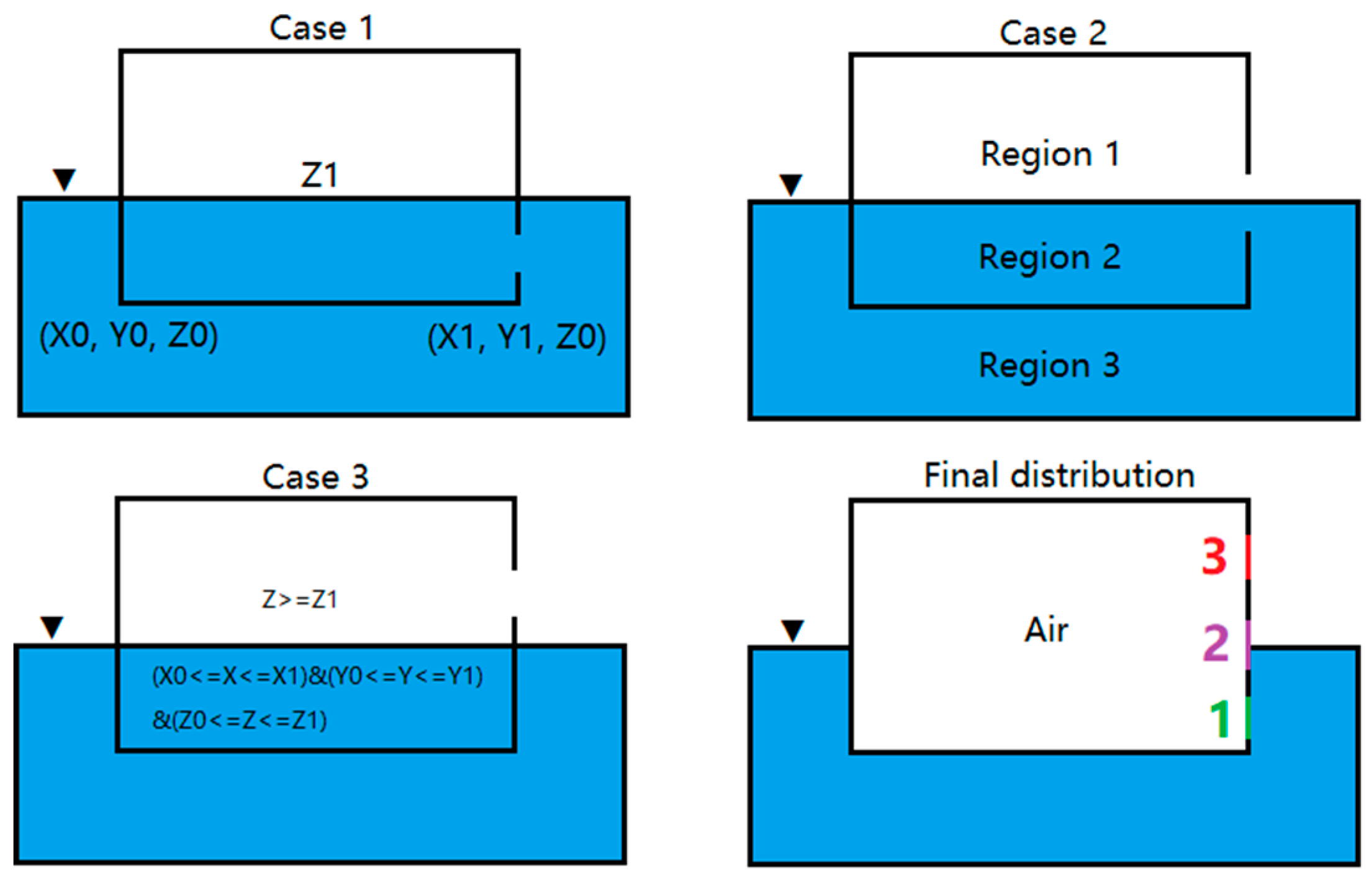
2.3. User Defined Field Function

In the CFD simulation program, a virtual towing tank is created by Boolean subtraction from the ship and the background region. As the ship has an opening, the default initial condition is that the damaged compartment is filled with water at the beginning, even if the lower edge of the opening is above the free surface (case 3). As shown in Figure 1 (case 1, case 2, case 3), the free surface in the damaged compartment is at the same level as the external water, which makes it impossible to simulate the entire flooding process. Therefore, it is necessary to manually define the initial condition of the free surface by means of user defined field function. As shown in Figure 1 (case 2), the virtual towing tank can be divided into three regions: The region 1 above the free surface, the region 2 below the free surface in the damaged compartment and external region 3. In order to realize that the damaged compartment is filled with air in the initial state, region 2 can be isolated by the planes formed by the described coordinates in case 3, and the volume fraction of water is separately defined. The field function code can be expressed in a simplified way, as follows:
User defined field function: [Region 1]: [Region 2] = 0:1.
A value of 0 indicates that the volume fraction of water in the restricted mesh region is 0, that is, the space occupied by the mesh is filled with air in the initial state. If the mesh is not in the restricted region, a value of 1 will be defined for the remaining region to represent the water. The written field function is based on the C++ programming language. Through the defined field function code, the final air-fluid interface is described in Figure 1 (final distribution) at any opening position (1, 2, and 3). In this case, when the damage occurs, the pressure across the opening drives the flooding water into the damaged compartment. The entire flooding process is monitored in real time through the post-processing of the scalar scene. It is noted that this approach only applies to a regular compartment. If the damaged compartment is not regular, an enhanced user defined field function is required.

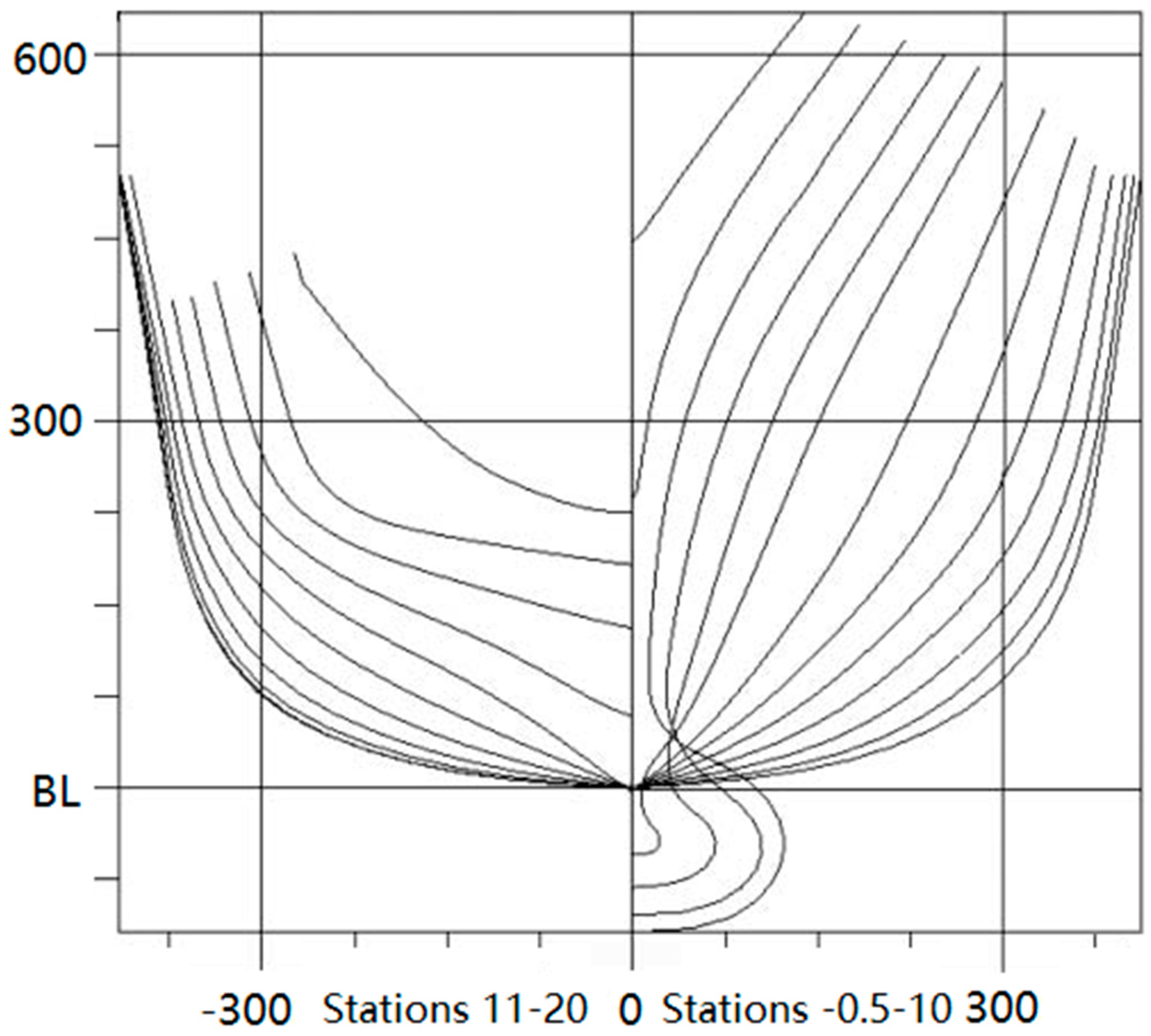
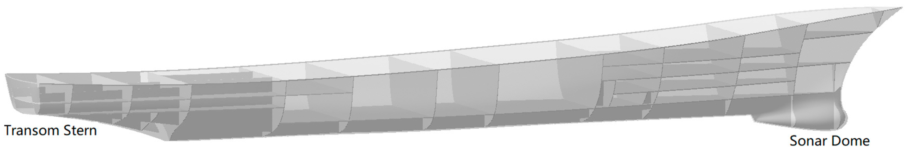
3. Description of DTMB Model 5415
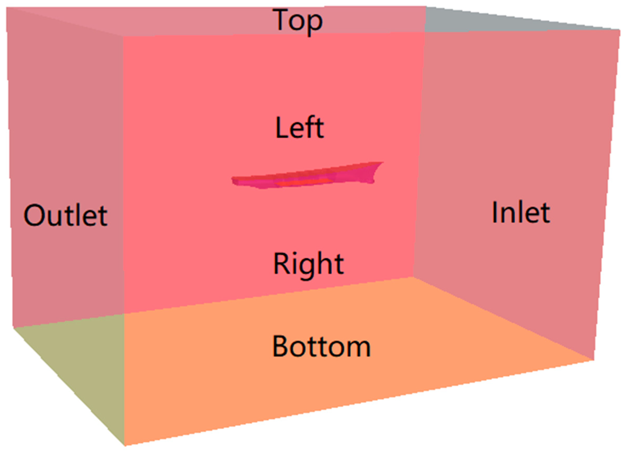
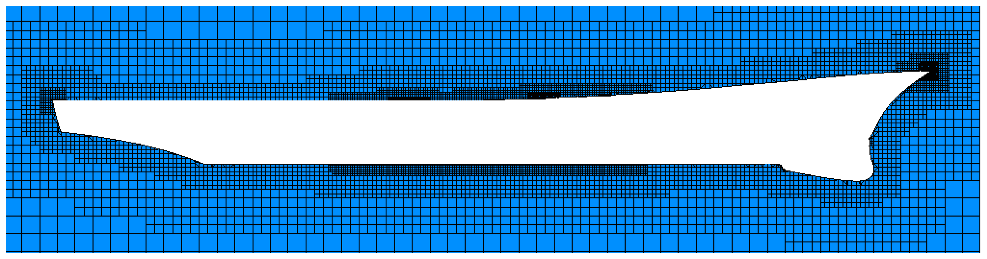
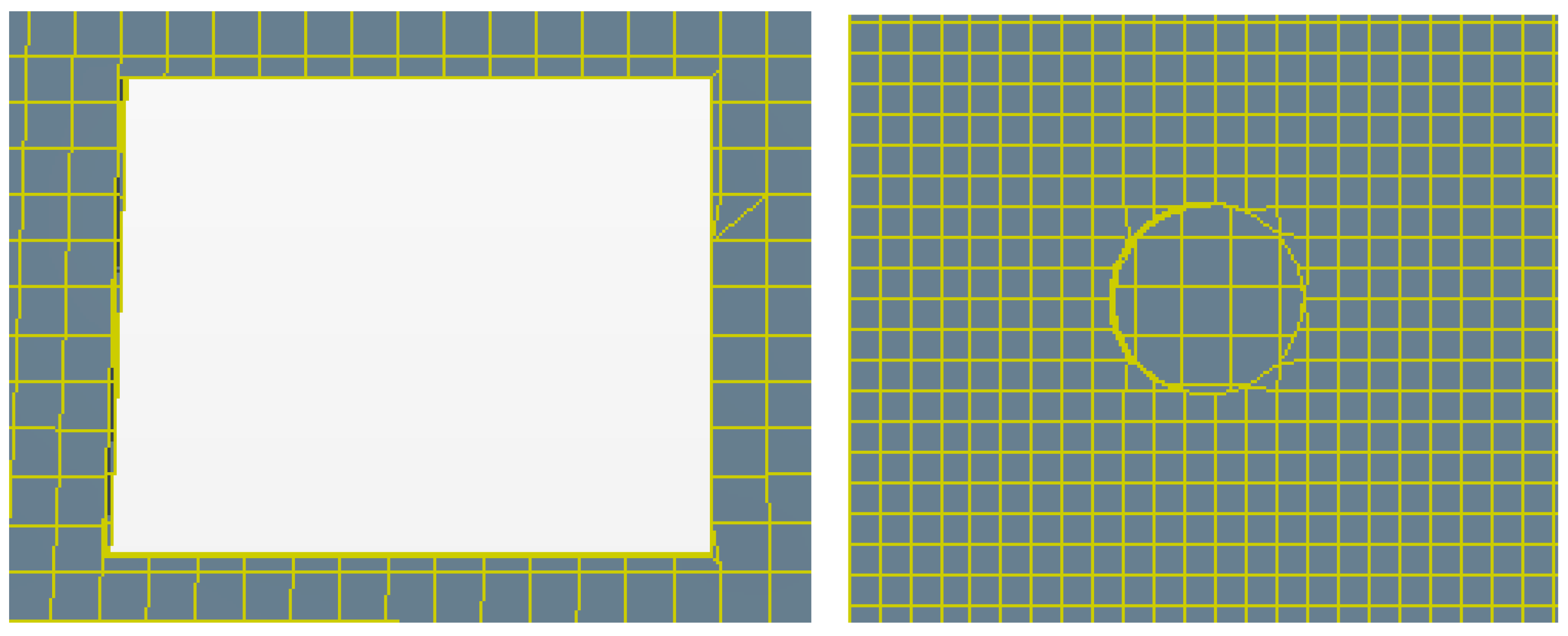
Several flooding cases have been carried out for the well-known benchmark US Navy Destroyer Hull DTMB 5415. All the simulations in this paper are established on the basis of the scale model (1/25). Table 1 presents the main dimensions of the scale model, whereas the views of the body plan and the scale model are respectively in Figure 2 and Figure 3. The internal compartment arrangement in Figure 3 is divided according to the described layout by Lee et al. [21]. The aim of compartment division is to be able to simulate the flooding path in a specific damage scenario. The established model has been simplified to a certain extent, and the flooded compartments are assumed to be empty. Some local structures that can modify the flow of the water are not taken into account, such as stiffeners, brackets, etc.
As illustrated in Figure 4, three comparative flooding cases with different damage positions (amidship, bow, and stern) are simulated separately. In order to reduce the effect of air compression on the flooding process, the decks and bulkheads are equipped with ventilation holes to ensure that the trapped air can escape from the flooded compartments. For a more realistic simulation of the hydrodynamic phenomenon due to air compression, the flooded compartments should be characterized with appropriate ventilation restrictions [14,15,16,22]. It can be found that different internal layouts result in distinct flooding forms. For the amidship damage, there is no obstruction in the damaged compartment, creating a flooding form symmetric. The flooding holes on both sides of the damaged compartment allows the water ingress to spread to adjacent compartments. The entire flooding process involves multiple compartments on a single deck. For the bow damage, due to the flooding hole on the lower deck of the damaged compartment, the flooding water flows downward under gravity at the beginning. As the flooding water continues to spread through the flooding holes in the bulkhead, the free surface in the flooded compartment eventually spreads to the same level as the external sea level. Similar to the bow damage, the stern damage is also a multi-compartment flow between multiple decks, and the flooding form is asymmetric. However, due to the relatively low damage position and the flooding hole on the upper deck of the damaged compartment, the flooding water flows upward under the excitation of hydrostatic pressure at the damaged opening. The specific opening size, flooding hole size, and ventilation hole size are summarized in Table 2.

4. Numerical Setup

In the simulation process, the damaged ship is placed in quasi-statics water, ignoring the composite effect of wind and wave on the flooding process. An implicit unsteady solver has been applied to control the update at each physical time for the calculation, and each physical time involves some number of inner iterations to converge the solution for that given instant of time. These inner iterations can be accomplished using implicit spatial integration or explicit spatial integration schemes. Generally, it is not easy to quantify the number of inner iterations per physical time-step for a given problem and desired transient accuracy. It is necessary to find an optimal balance between time-step size and the number of inner iterations through several attempts, ensuring that the computational effort is relatively economical and calculating results are converging within each time-step. According to the practical guidelines for ship CFD application [23] and the gathered experience, the simulation cases in this paper applied a constant physical time-step of 0.004 s, involving 10 inner iterations. In order to numerically solve the system of partial differential equations that govern the flow, the implicit unsteady solver in STAR-CCM+ includes the transient term and offers two temporal discretization options: First-order and second-order. The second-order temporal scheme applied in this paper discretizes the unsteady term using the solution at the current time level, as well as the solutions from the previous two time-levels. Generally, the first-order temporal scheme is also temporally activated when the second-order temporal scheme is activated. As the initial solutions at the beginning, two time-levels must be from the first-order temporal scheme. For the convection term, the second-order upwind scheme is utilized to compute the convective flux. Even if the second-order upwind scheme applied in this paper may result in poorer convergence properties, the accuracy of this scheme is always as good or better than the first-order upwind scheme. In addition, the Reynolds stress is solved by means of the realizable K-Epsilon turbulence model, which is substantially better than the standard K-Epsilon turbulence model for many applications and generally give more precise simulation results [19]. In order to clearly capture the dynamic changing process of the free surface, the VOF approach and user defined field function are combined to carry out the time domain simulations. The specific governing equations and defined code have been elaborated in Section 2.
After comprehensive understanding of the published papers [24,25] and the demonstration case of the KCS Hull with a rudder in STAR-CCM+ user’s version [19], the simulation domain is arranged as shown in Figure 5, and the appropriate boundary conditions and solver settings are summarized in Table 3. The domain dimensions are set relative to the ship length. One ship length is modelled upstream, below and to the side. Two ship lengths are modelled downstream of the ship [23]. For the mesh generation, a trimmed mesh of hexahedral type is applied as illustrated in Figure 6. In Begovic et al. [24], the detailed sensitivity analysis of mesh types to computational results has been performed with two trimmed meshes and two hybrid meshes (polyhedral and trimmed). The comparing results indicate that the hexahedral trimmed mesh yields a good compromise between computational effort and simulation accuracy. For the motion responses of the damaged ship, the damaged ship is set to be stationary in the 6-DOF (degree of freedom) solver, constraining the movements in all directions. Although this approach is an ideal assumption, it is meaningful to some degree for the preliminary investigation of the flooding process.
It is well known that the optimal mesh quality guarantees the convergence of the numerical simulation and the accuracy of the simulation results. For the simulation cases in this paper, the mesh size at the damage opening and ventilation holes must be locally refined. As the mesh is coarse, the shape is not totally remeshed and the geometry is distorted, and the calculation accuracy cannot be guaranteed. As shown in Figure 7, the meshes at the opening and ventilation hole in this paper are refined in the mesh generation solver, restoring the original geometry. Under the premise of ensuring the mesh quality, the generated cell number and the total calculation time on a single CPU (Intel i7-8700) are presented in Table 4. As the flooded region of the amidship damage is relatively larger to the bow and stern damage, more mesh refinement results in the largest cell number. In addition, if there are small gaps and overlaps in the imported geometric surface, it is necessary to activate the surface wrapper function.

5. Simulation Results

The applied numerical approach in this paper visualizes the entire flooding process, enhancing the comprehension of complex fluid-structure interaction and hydrodynamic behaviors. The following simulation results separately detail the relevant flooding characteristics through the three damage scenarios described in Section 3, including the effect of air compression on the flooding amount and the effect of flooding time on the rescue options and evacuation paths.

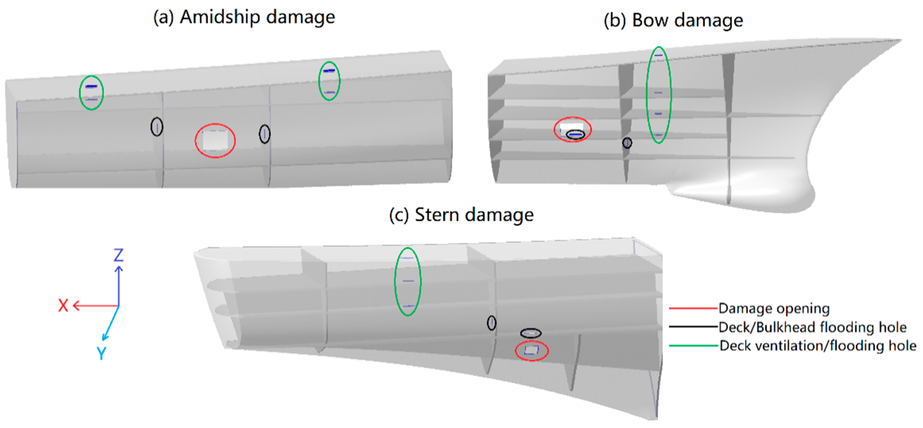
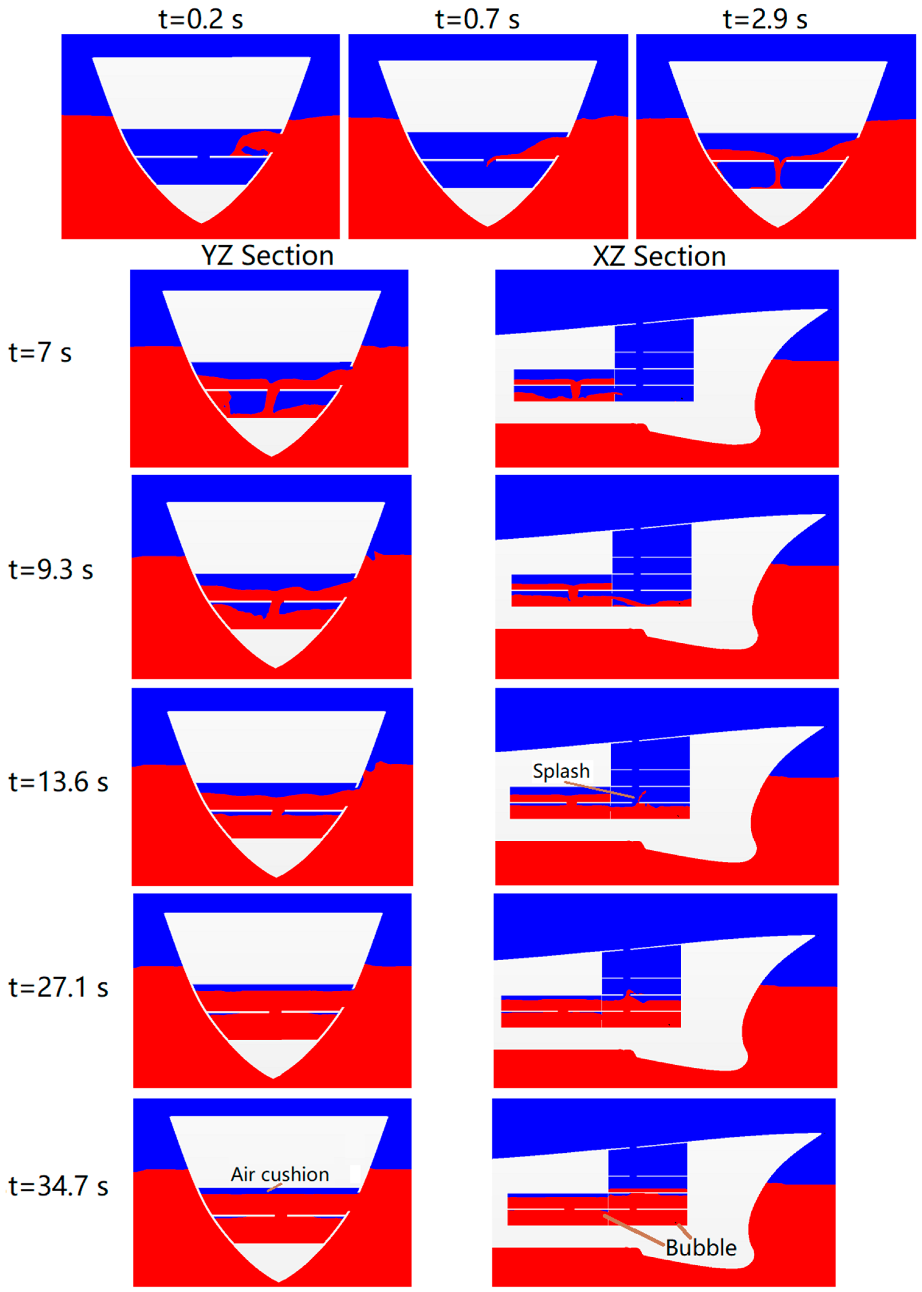
5.1. Amidship Damage

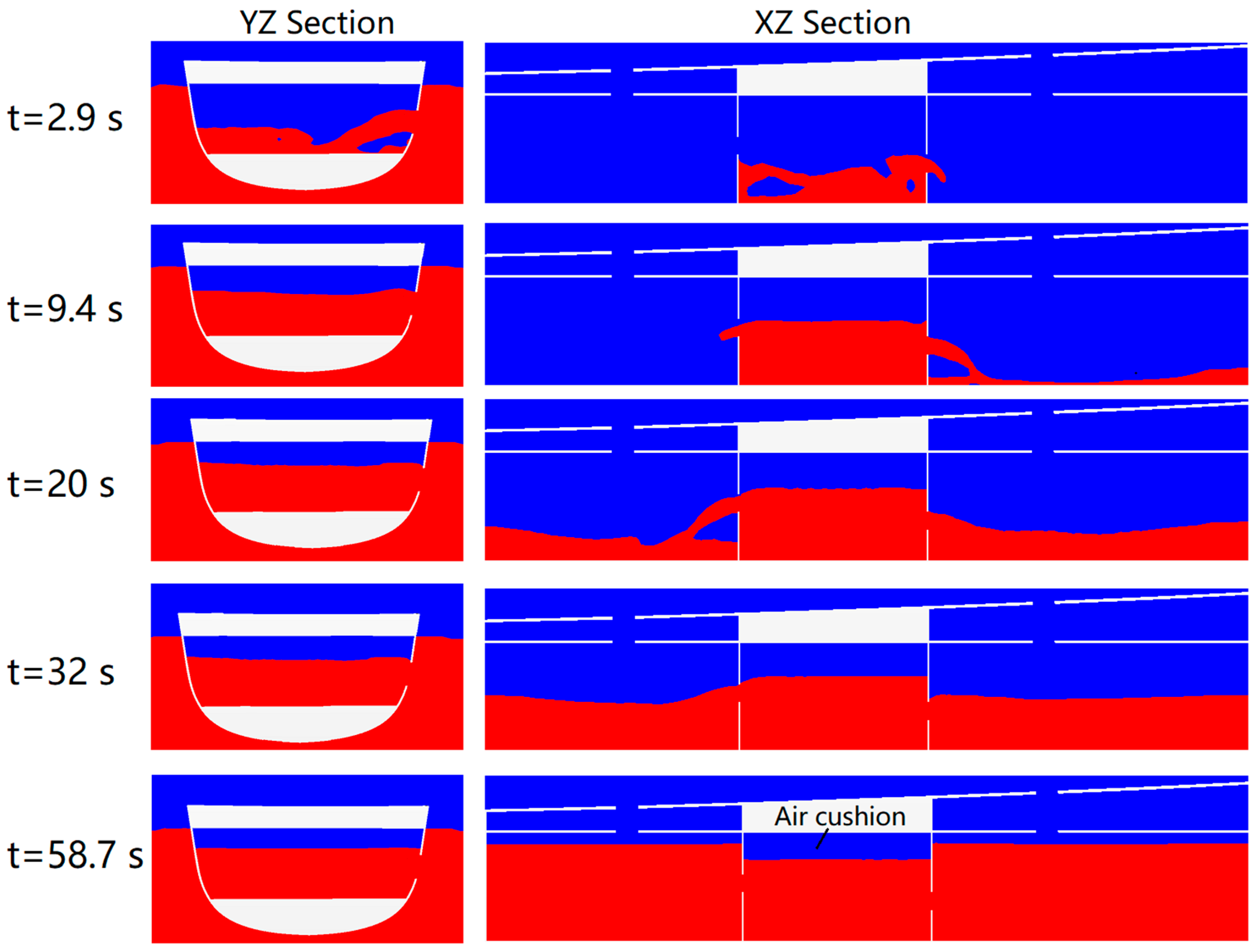
5.1.1. Transient Flooding Stage

In general, the transient flooding stage is short but violent and complex, so it should be given priority in flooding analysis. In this case, the flooding process of a symmetric void compartment in the amidship damage scenario was chosen to describe it in detail. Figure 8 shows the free surface at different times in the initial phase, with the aim of capturing the complex hydrodynamic phenomena. In a short period of 2.8 s, the amount of flooding water is relatively large compared to the volume of the flooded compartment, which also verifies the violent characteristic of the transient flooding stage. Under the excitation of external hydrostatic pressure, there was a significant jet response at the damaged section at 0.5 s. Then, after the flooding water slammed the left bulkhead, there was a noticeable liquid tumbling at 0.9 s, and the free surface flipped at 2.4 s. At 2.8 s, since a large amount of flooding water poured into the damaged compartment in a short time, the bubble formed by the gas-liquid interaction was found. These various hydrodynamic behaviors demonstrate the complexity of the transient flooding stage. All captured hydrodynamic behaviors are useful to form a deeper understanding of the flooding process.

5.1.2. Air Compressibility in the Damaged Compartment
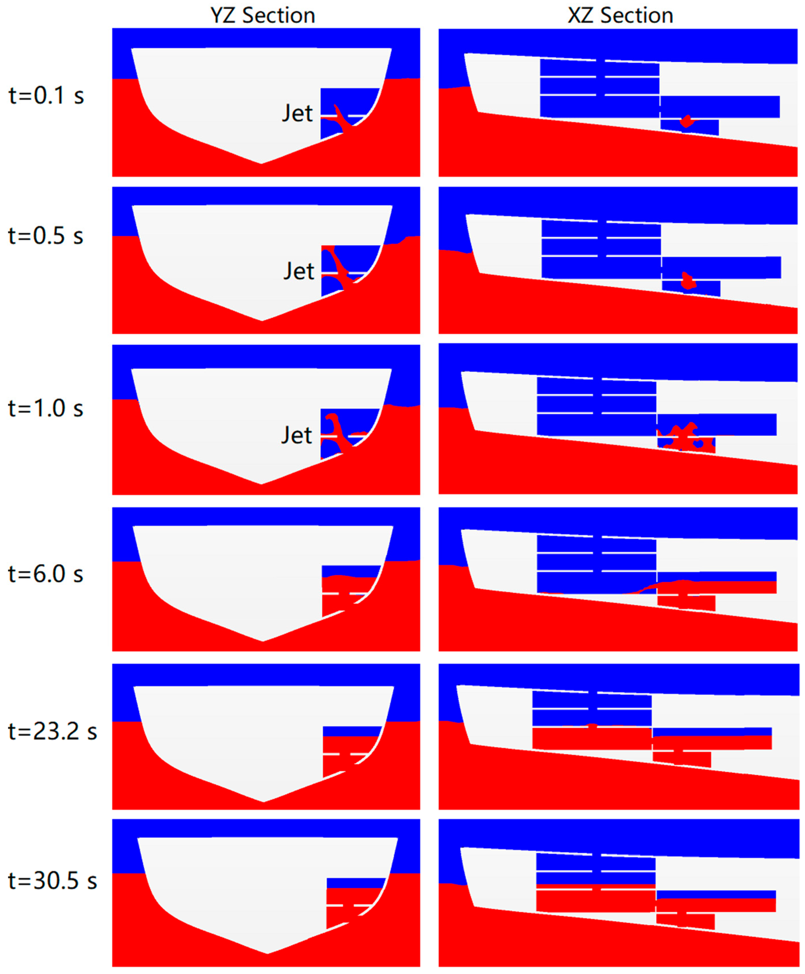
In the process of ship design, in order to reduce the weight of the ship and facilitate the crew to move between the internal compartments, the bulkheads are often equipped with lightening holes or manholes. This causes the flooding water to progress into adjacent compartments when the damage occurs. This situation is common for merchant vessels. However, for the navy vessel DTMB 5415, this kind of damage scenario can be considered a hypothetical scenario. Therefore, in the amidship damage case, two openings with different heights are set on both sides of the damaged compartment. As illustrated in Figure 9, the YZ section shows the flooding process of the damaged compartment, while the XZ section represents the flow process of the flooding water to both sides. From the figure of the YZ section, it was found that with the development of flooding damage, the height of the free surface in the damaged compartment was continuously increasing, but the final height was still lower than the external free surface. Through the XZ section a final height difference was found between the damaged compartment and the adjacent compartments. The reason is that there are no ventilation holes at the top of the damaged compartment. When the height of free surface in the damaged compartment simultaneously exceeds the upper edge of the left and right openings, the trapped air in the damaged compartment has no escape path and creates an air cushion in the top of the damaged compartment. Once the air pressure reaches a threshold value, the flooding water in the damaged compartment no longer increases. Since the tops of the adjacent compartments are provided with ventilation holes, the following flooding water from external sea flows to the adjacent compartments, and the final height of the free surface is consistent with the external sea level. This also explains that in the early stage of ship design, in order to increase the ship’s unsinkability, the watertight subdivision is strictly satisfied to the minimum requirements of damage stability required by the Classification Registers. It reduces the flooding amount to a certain extent, so as to improve the survivability of the damaged ship.

5.2. Bow Damage

5.2.1. Analysis of the Bow Damage Flooding

Unlike the amidship damage scenario, the flooding water in the bow damage penetrated through multiple decks. As shown in Figure 10, the flooding water pours into the damaged compartment under the combined excitation of hydrostatic pressure and gravity, and then gradually flows into the adjacent compartments through the internal holes. Simultaneously, the splash is visible, and the free surface near the damaged opening fluctuates due to the complex flooding flow. The trapped air eventually creates an air cushion at the top of the damaged compartment, impeding the flooding water from occupying the entire compartment. It was also found that during the period of 27.1 s to 34.7 s, although the free surface of the two compartments on the YZ section tended to be steady, the ingress of the three compartments on the XZ Section continued until the height of the free surface in the last flooded compartment was the same as the external sea level. In this progressive stage, a small portion of compressed air remains in the flooding water, forming a small bubble phenomenon. An additional critical factor that affects the progression of the flooding water is the permeability of the compartment. The simulations performed in this paper are based on the assumption that the flooded compartments are empty, not considering the effect of obstacles (cargo, facility, local structure, etc.) on the compartment permeability. In order to capture these microscopic hydrodynamic phenomena in detail, it is recommended to set a finer mesh in the studied flooding region. Furthermore, it is important to observe that active counter measures, such as pumping and ballast operations, are not considered. In a ship, these counter measures are associated with systems as bilge, drainage, and ballast. These systems in emergency conditions can be used to pump out the flooding water from the flooded compartment. The effectiveness of these systems is significant, in particular, during the slow flooding scenario. These systems can also be used in the fast flooding scenario where the flooding water cannot be pumped out completely. These systems increase the time to flood a compartment, thereby improving the ship’s survivability.

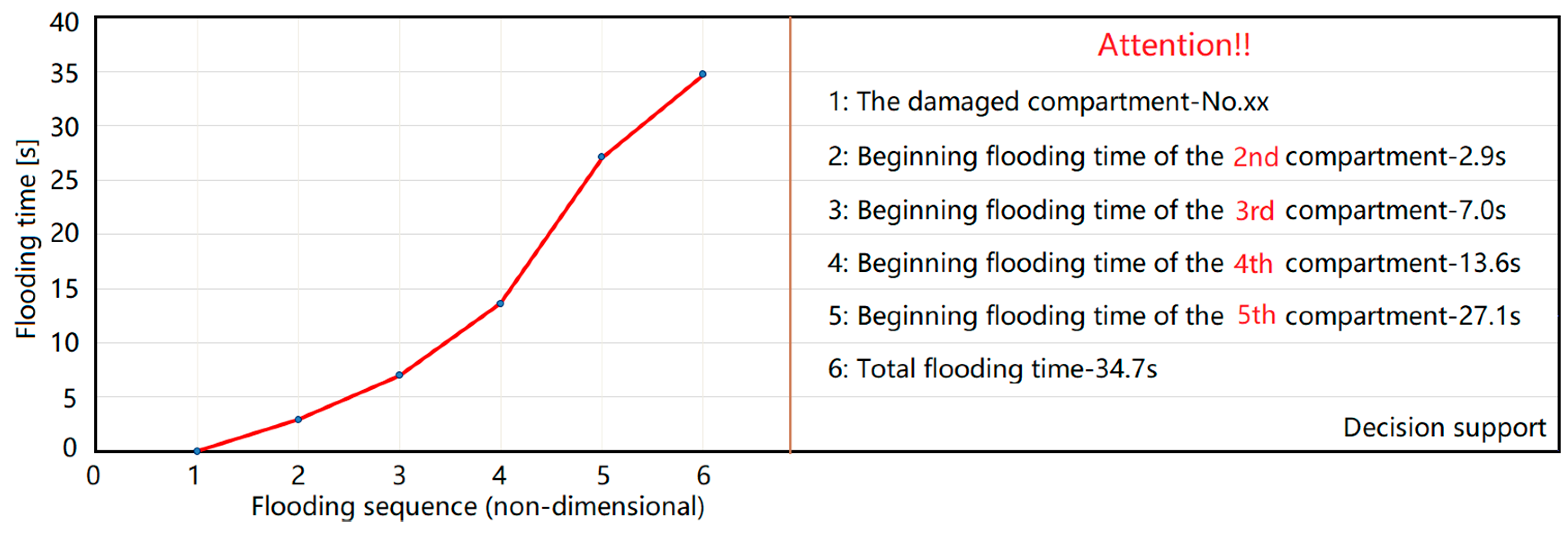
5.2.2. Rescue Management on the Basis of the Flooding Time
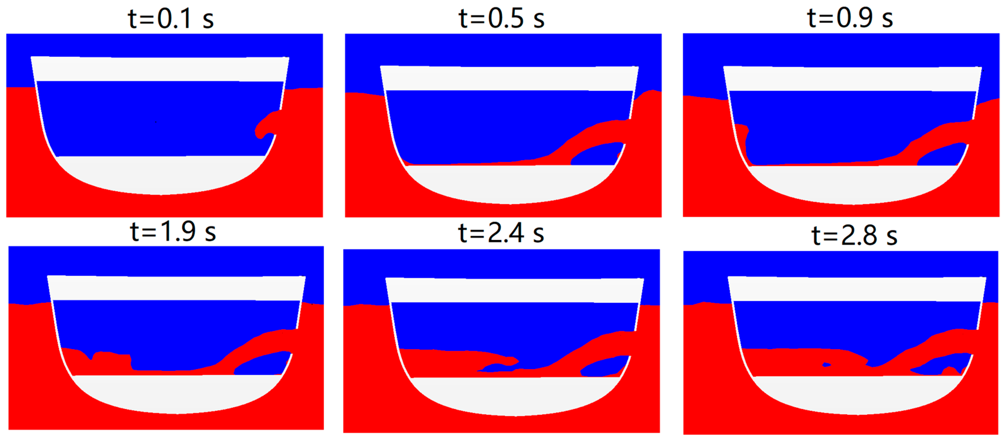
By analyzing the above flooding process, it is feasible to capture the flooding process with the advanced CFD technique and a high-performance computing facility, but ultimately this research needs to be made more accessible to seafarers. Since the seafarers may not be interested in the simulation approach, they are more likely to get more effective and efficient advice on how to conduct appropriate rescue management. Figure 11 presents the post-processing results of the flooding time based on the flooding process. The obtained flooding sequence and beginning flooding time provides more convenience for leaking stoppage. When the damage occurs, the onboard decision support system should firstly inform the captain of the damage location and the moments when the potential flooded compartments begin to flood. This is very critical for the captain to develop the damage control and limitation plan. If a compartment is about to be occupied by the flooding water in a short time, in order to ensure the safety of the emergency personnel, it is impossible to command the emergency personnel to perform the stopping operation. For example, in the case of the bow damage, the second and third compartment began to flood for 2.9 s and 7 s respectively. If the emergency team failed to block the internal flooding holes, the subsequent flooding water is a threat to their lives. In this case, the captain should consider blocking the third and fourth compartments because their beginning flooding time is relatively adequate, at 13.6 s and 27.1 s respectively. The worst is that the emergency team are limited in ability to take any remedial measures, the captain can also strengthen the adjacent important compartment according to the total flooding time, avoiding the additional flooding water load destroys the integrity of other structures. This is because hydrostatic from the accumulation of the flooding water causes significant leakage and collapses weak loading-bearing structures [26]. In short, the investigation of the flooding process enhances the safety of the onboard personnel and the survivability of the damaged ship. In the future, the fast prediction of the flooding results and the data fusion with onboard decision support system will be challenging.

5.3. Stern Damage

5.3.1. Analysis of the Stern Damage Flooding

During modelling of the stern damage scenario, it is intended to place the damaged opening far away from the free surface. Thus, when the damage occurs, an enormous pressure head at the damaged opening drives the flooding water into the damaged compartment. In addition, there is another point that distinguishes the bow and middle damage scenarios. In the case of the bow and middle damage scenarios, the initial flooding water flows to the lower deck under the combined excitation of hydrostatic pressure and gravity. However, in the transient stage of the stern damage, the hydrostatic pressure first resists the downward effect of gravity and then causes the flooding water to slam on the top of the compartment in the form of a jet. As shown in Figure 12, the flooding water slams the top of the compartment within 1 s. In just 6 s, the flooding water basically occupied the flooded compartments on the YZ section. Consequently, the height of the free surface on the YZ section does not change. Due to the pressure difference between the internal and external hydrostatic pressures, the compartments on the XZ section were still continuously flowing until it steadied at 30.5 s. Through the analysis of this scenario, not only the hydrodynamics phenomena in the above two cases were observed, but also it can explained why some damaged ships have a large amplitude roll motion or capsize in a short time in the transient stage. The reason is that the transient flooding water causes a large impact load, which may exceed the design margin of the ship’s stability.

5.3.2. Possibilities of Evacuation and Counter Actions on the Basis of the Flooding Time

In order to enhance maritime safety, the onboard emergency personnel not only need to make reasonable leakage-stopping measures according to the time of flooding moments, but also need to establish a safe evacuation route for other personnel. If the planned evacuation path overlaps with the flooding path at a certain moment, life security of the passengers or soldiers is threatened. Figure 13 presents the post-processing results of the stern flooding process, which is utilized to guide the reasonable evacuation of the onboard personnel. The decision support on the right shows that when the damage occurs, the transient flooding water occupies the first and second flooded compartments in a short time. The two compartments are prohibited from passing, and the planning evacuation route also excludes the two compartments. For the third and fourth flooded compartment, the optimal evacuation path is dynamically updated based on the displayed flooding moments. In addition, the entire flooding process only lasts 30 s, which requires the captain to make fast decisions to ensure the safety of personnel. Investigation on the flooding process can provide inherent data support for the evacuation guidance. The flooding time is relatively short (about 30 s), leaving not enough time for orderly evacuation between potential flooded compartments. At least, the captain should warn the crew not to pass through these dangerous compartments, thus fully eliminating the threat to life by the flooding water. From another perspective, the emergency personnel should take reasonable counter actions to drain the flooding water from the flooded compartments. This can both slow down the flooding rate to increase the rescue time and also facilitate the choice of evacuation paths. Generally, all simulation cases were performed on the scale model (1/25). Therefore, the flooding time in the full-scale model is expected to be 5 times slower than the scale model. This conversion is based on the Froude law that time is proportional to the square root of the scale. Taking the stern damage as an example, 30 s in the scale model is equivalent to 2 min 30 s in the full scale model. From this point of view, accurately estimating the flooding time of the scale model is meaningful for both rescue management and evacuation option in full scale model.

6. Conclusions and Future Researches

A comprehensive understanding of the flooding process is paramount to those who work at sea and the operators of the ship. The approach developed in this paper captures the complex hydrodynamic behaviors in the flooding process, especially the transient flooding stage, including jet, splash, bubble, air cushion, etc. The obtained post-processing results provide reliable guidance for rescue management and evacuation options. However, only numerical results have been provided, without comparison with experimental data. Subsequently, model tests combined with numerical simulation can be performed to validate the reliability of the simulated results.
In the future, more complicated damage scenarios will be modelled and simulated. For example, firstly, the effect of the coupled motion on the flooding process can be studied. Secondly, is the effect of different compartment permeability on the flooding process and motion response. Thirdly, the real environment can be taken into consideration, including forward speed and various wave types. In addition, the serious challenge for the CFD methods for flooding simulation lies in the extremely high time consumption. Therefore, how to strike a balance between solution accuracy and computational effort is one of the most important factors when applying CFD simulation to enhance maritime safety in the future.

Author Contributions

X.Z. performed the numerical simulation and wrote the paper. Z.L. (Zhuang Lin) provided the detailed model information, proposed the research idea and revised the paper. S.M. reviewed and revised the paper. P.L. collected references and summarized the research background. Z.L. (Ze Li) divided the internal compartment layout and post-processed the simulation results. F.L. derived and analyzed CFD theoretical formula.

Funding

This research was funded by the National Natural Science Foundation of China (NSFC Grants 51709063).

Acknowledgments

The authors thank Yue Dong and Meiqi Wang for their assistance in the simulation setting. We also thank two anonymous reviewers for their valuable comments and suggestions that help us improve the manuscript.

Conflicts of Interest

The authors declare no conflicts of interest.

References

  1. Gao, Z.; Vassalos, D. The dynamics of the floodwater and damaged ship in waves. J. Hydrodyn. 2015, 27, 689–695. [Google Scholar] [CrossRef]
  2. IMO. Large Passenger Ship Safety: Time-to-Flood Simulations for a Large Passenger Ship-Initial Study, IMO SLF46/INF.3 MARIN Report No.17870-1-CPS; IMO: London, UK, 2003; p. 40. [Google Scholar]
  3. Ruponen, P.; Manderbacka, T.; Lindroth, D. On the calculation of the righting lever curve for a damaged ship. Ocean Eng. 2018, 149, 313–324. [Google Scholar] [CrossRef]
  4. Gao, Z.; Gao, Q.; Vassalos, D. Numerical simulation of flooding of a damaged ship. Ocean Eng. 2011, 38, 1649–1662. [Google Scholar] [CrossRef]
  5. The specialist committee on prediction of extreme ship motions and capsizing (chaired by D. Vassalos). In Proceedings of the 23th International Towing Tank Conference (ITTC), Venice, Italy, 2002.
  6. Stability in Waves Committee, Final Report and Recommendation (chaired by P. Gualeni). In Proceedings of the 28th International Towing Tank Conference (ITTC), Wuxi, China, 2017.
  7. Rodrigues, J.M.; Lavrov, A.; Hinostroza, M.A.; Guedes Soares, C. Experimental and numerical investigation of the partial flooding of a barge model. Ocean Eng. 2018, 169, 586–603. [Google Scholar] [CrossRef]
  8. Ruponen, P.; Kurvinen, P.; Saisto, I.; Harras, J. Air compression in a flooded tank of a damaged ship. Ocean Eng. 2013, 57, 64–71. [Google Scholar] [CrossRef]
  9. Lee, S.; You, J.M.; Lee, H.H.; Lim, T.; Rhee, S.H.; Rhee, K.P. Preliminary tests of a damaged ship for CFD validation. Int. J. Nav. Archit. Ocean Eng. 2012, 4, 172–181. [Google Scholar] [CrossRef] [Green Version]
  10. Manderbacka, T. Fast Simulation Method for Transient Flooding of a Ship. Ph.D. Thesis, Aalto University, Helsinki, Finland, 2015. [Google Scholar]
  11. Ruponen, P.; Pulkkinen, A.; Laaksonen, J. A method for breach assessment onboard a damaged passenger ship. Appl. Ocean Res. 2017, 64, 236–248. [Google Scholar] [CrossRef]
  12. Sadat-Hosseini, H.; Kim, D.H.; Carrica, P.M.; Rhee, S.H. URANS simulations for a flooded ship in calm and regular beam waves. Ocean Eng. 2016, 120, 318–330. [Google Scholar] [CrossRef]
  13. Skaar, D.; Vassalos, D.; Jasionowski, A. The use of a meshless CFD method in modelling progressive flooding and damaged stability of ships. In Proceedings of the Ninth International Conference on Stability of Ships and Ocean Vehicles, Rio Janeiro, Brazil, 25–29 September 2006; pp. 625–632. [Google Scholar]
  14. Zhang, X.L.; Lin, Z.; Li, P.; Dong, Y.; Liu, F. Time domain simulation of damage flooding considering air compression characteristic. Water 2019, 11, 796. [Google Scholar] [CrossRef]
  15. Cao, X.Y.; Ming, F.R.; Zhang, A.M.; Tao, L. Multi-phase SPH modelling of air effect on the dynamic flooding of a damaged cabin. Comput. Fluids 2018, 163, 7–19. [Google Scholar] [CrossRef]
  16. Palazzi, L.; De Kat, J. Model experiments and simulations of a damaged ship with air flow taken into account. Mar. Technol. 2004, 41, 38–44. [Google Scholar]
  17. Manderbacka, T.; Mikkola, T.; Ruponen, P.; Matusiak, J. Transient response of a ship to an abrupt flooding accounting for the momentum flux. J. Fluid Struct. 2015, 57, 108–126. [Google Scholar] [CrossRef] [Green Version]
  18. Acanfora, M.; Begovic, E.; De Luca, F. A Fast Simulation Method for Damaged Ship Dynamics. J. Mar. Sci. Eng. 2019, 7, 111. [Google Scholar] [CrossRef]
  19. STAR-CCM+ Users’ Guide Version 12.02. CD-Adapco, Computational Dynamics-Analysis & Design; Application Company Ltd.: Melville, NY, USA, 2012.
  20. Menter, F.R. Eddy Viscosity Transport Equations and Their Relation to the k-ε Model. J. Fluids Eng. 1997, 119, 876–884. [Google Scholar] [CrossRef]
  21. Lee, Y.; Chan, H.S.; Pu, Y.; Incecik, A.; Dow, R.S. Global Wave Loads on a Damaged Ship. Ships Offshore Struct. 2012, 7, 237–268. [Google Scholar] [CrossRef]
  22. Gao, Z.; Wang, Y.; Su, Y. Numerical study of damaged ship’s compartment sinking with air compression effect. Ocean Eng. 2018, 147, 68–76. [Google Scholar] [CrossRef]
  23. Practical Guidelines for ship CFD Application. In Proceedings of the 26th International Towing Tank Conference (ITTC), Rio de Janerio, Brazil, 28 August–3 September 2011.
  24. Begovic, E.; Day, A.H.; Incecik, A.; Mancini, S. Roll damping assessment of intact and damaged ship by CFD and EFD methods. In Proceeding of the 12th International Conference on the Stability of Ships and Ocean Vehicles, Glasgow, UK, 19–24 June 2015. [Google Scholar]
  25. Mancini, S.; Begovic, E.; Day, A.H.; Incecik, A. Verification and validation of numerical modelling of DTMB 5415 roll decay. Ocean Eng. 2018, 162, 209–223. [Google Scholar] [CrossRef] [Green Version]
  26. Risto, J.; Pekka, R.; Mateusz, W.; Hendrik, N.; Sander, V. A Study on Leakage and Collapse of Non-Watertight Ship Doors under Floodwater Pressure. Mar. Struct. 2017, 51, 188–201. [Google Scholar]
Figure 1. The initial distribution of free surface under different damage locations.
Jmse 07 00211 g001
Figure 2. Body plan of DTMB 5415 (Unit: inch).
Jmse 07 00211 g002
Figure 3. A perspective view of the DTMB model 5415.
Jmse 07 00211 g003
Figure 4. Different damage scenarios.
Jmse 07 00211 g004
Figure 5. Sketch of the simulation domain.
Jmse 07 00211 g005
Figure 6. Hexahedral trimmed mesh.
Jmse 07 00211 g006
Figure 7. Local mesh refinement at the damage opening and ventilation holes.
Jmse 07 00211 g007
Figure 8. The capture of hydrodynamic behaviors in the transient stage.
Jmse 07 00211 g008
Figure 9. A description of flooding characteristics for the amidship damage.
Jmse 07 00211 g009
Figure 10. A description of flooding characteristics for the bow damage.
Jmse 07 00211 g010
Figure 11. Post-processing results of the bow flooding process.
Jmse 07 00211 g011
Figure 12. A description of flooding characteristics for the stern damage.
Jmse 07 00211 g012
Figure 13. Post-processing results of the stern flooding process.
Jmse 07 00211 g013
Table 1. Main particulars of US Navy Destroyer Hull 5415.
ParametersParticularsReal ShipScale Model (1/25)
Length Overall L O A (m)151.18006.0472
Length between perpendiculars L p p (m)142.04005.6856
Breadth at Waterline B W L (m)20.03000.8012
Depth to public spaces deckD (m)12.74000.5096
Design draftT (m)6.31000.2524
VolumeV ( m 3 )8811.940.5640
Maximum section area A X ( m 2 )96.79230.1549
Block coefficient C B 0.49090.4909
Prismatic coefficient C P 0.64090.6409
Midship section coefficient C M 0.76580.7658
Height of metacenter above keelKM (m)9.47000.3788
Height of Centre of Gravity above keelKG (m)6.28300.2513
Metacentric heightGM (m)3.18700.1272
Longitudinal Centre of GravityLCG (m)71.02002.8408
Table 2. Specification of damage openings and flooding/ventilation holes.
Local PartsAmidshipBowStern
Damage Opening 80 × 100   mm 60 × 100   mm 20 × 30   mm
Deck Flooding Hole 40 × 60   mm 30 × 30   mm
Bulkhead Flooding Hole 40 × 60   mm 30 × 50   mm Radius10 mm
Deck Ventilation HoleRadius25 mmRadius20 mmRadius15 mm
Table 3. The boundary conditions and solver setting summary.
Boundary NameBoundary Type (This Paper)Boundary Type [24,25]Boundary Type [19]
InletVelocity inletVelocity inletVelocity inlet
OutletPressure outletVelocity inletPressure outlet
Top/BottomVelocity inletVelocity inletVelocity inlet
Left/RightSymmetry planePressure outletSymmetry plane
HullWallWallWall
Convection TermSecond-orderSecond-orderFirst-order (Default)
Temporal DiscretizationSecond-orderSecond-orderFirst-order (Default)
Table 4. The cell number and calculation time for different damage scenarios.
ParametersAmidshipBowStern
Cell number ( 10 6 )2.0241.4081.262
CPU time (h)16112395

