Article

Large-Scale Electric Propulsion Systems in Ships Using an Active Front-End Rectifier

1
Department of Marine System Engineering, Korea Maritime and Ocean University, 727 Taejong-ro, Busan 49112, Korea
2
Department of Electricity, Ulsan Campus of Korea Polytechnics, 155 Sanjeon-gil, Ulsan 44482, Korea
*
Author to whom correspondence should be addressed.
J. Mar. Sci. Eng. 2019, 7(6), 168; https://doi.org/10.3390/jmse7060168
Submission received: 1 May 2019 / Revised: 24 May 2019 / Accepted: 30 May 2019 / Published: 1 June 2019
(This article belongs to the Special Issue Ship Lifecycle)

Abstract

:
In the case of the electric propulsion system on the vessel, Diode Front End (DFE) rectifiers have been applied for large-sized ships and Active Front End (AFE) rectifiers have been utilized for small and medium-sized ships as a part of the system. In this paper, we design a large electric propulsion ship system using AFE rectifier with the proposed phase angle detector and verify the feasibility of the system by simulation. The phase angle derived from the proposed phase angle detection method is applied to the control of the AFE rectifier instead of the zero-crossing method used to detect the phase angle in the control of the conventional AFE rectifier. We compare and analyze the speed control, Direct Current (DC)-link voltage, harmonic content and measurement data of heat loss by inverter switch obtained from the simulation of the electric propulsion system with the 24-pulse DFE rectifier, the conventional AFE rectifier, and the proposed AFE rectifier. As a result of the simulation, it was confirmed that the proposed AFE rectifier derives a satisfactory result similar to that of a 24-pulse DFE rectifier with a phase shifting transformer installed according to the speed load of the ship, and it can be designed and applied as a rectifier of a large-sized vessel.

1. Introduction

As environmental pollution has become a global issue, the International Maritime Organization (IMO) has been strengthening regulations on emissions of sulfur oxides, nitrogen oxides, and carbon dioxide from ships [1,2]. As a result of that various researches are being carried out in order to cope with environmental regulations that are strengthening internationally in the shipbuilding and shipping industries [3]. Moreover, the electric propulsion system of vessels with propulsion motors is also one of emerging countermeasures [4,5,6,7]. As shown in Figure 1, the order of environmentally friendly electric propulsion ship is dramatically increased on 2017 World Fleet Resister by Clarkson’s Research [8].
The components of the conventional large-sized electric propulsion ship are generally composed of generator, DFE rectifier with phase shifting transformer, inverter and propulsion motor, and it is possible to design the size of the engine room with some margin [9,10,11]. In an electric propulsion ship, when the switching of inverters occurs, a harmonic current is generated in a power system [12]. Thus, large and small problems occur in the generator, transformer, and propulsion motor. Various methods for reducing harmonics have been studied. In the case of large electric propulsion systems, phase shifting transformer has been adopted as the most common method of installing a transformer on the output side of a generator [3,13]. There are various methods of harmonics reduction of the DFE rectifier using a phase shifting transformer, such as multi-pulse of the rectifier output [14,15,16], active filter installation [17], and improvement of the transformer connection method [18,19,20].
However, when the phase shifting transformer is installed, there is a disadvantage as installation space and cost increase. Moreover, it is difficult to apply it to a small and medium-sized ship with limited space. AFE rectifiers have been mainly applied to small and medium-sized electric propulsion ships [21,22], but recently, as the technologies of power semiconductors with high capacity and high speed switching characteristics have been developed, so that it is possible to model a large-sized electric propulsion system using AFE rectifier [23]. The AFE rectifier must be designed with a control circuit that can control the semiconductor switch, and it is especially necessary to accurately detect the phase angle of the power supply voltage. Zero crossing technique that can detect the phase angle quickly is simple and has no special control method [24,25,26,27]. However, due to the fluctuation of generator output voltage in case of high load, such as propulsion motor or bow thruster. The detection of the phase angle may not be performed momentarily. Various methods have been studied to overcome the severe disadvantage of this zero-crossing technique.
In large-sized commercial vessels, it is crucial to secure the space for cargo transportation as much as possible [3,9]. However, to reduce the harmonics contained in the ship power system, the DFE rectifiers with large-sized phase shifting transformer have a disadvantage to load cargo. And the AFE rectifier using the existing zero-crossing technique also has various problems [28,29].
In this paper, an AFE rectifier using the Phase Locked Loop (PLL) method is applied to a large electric propulsion system instead of the phase angle detection method using the zero-crossing method [30,31,32,33]. We used the power analysis program, Power Simulation (PSIM), to model an AFE rectifier that uses the PLL method. Comparison simulations were performed for large-scale electric propulsion systems with the conventional DFE as well as proposed AFE rectifiers. Based on this simulation, the resulting speed of the propulsion motor, DC output of the DC link, and harmonic output characteristics of the input power supply were analyzed based on the type of rectification. In addition, the thermal loss in the switching element, which is present in the inverter when AFE rectifiers are used, as well as its stability, were evaluated. Based on these results, the characteristics of the DFE and AFE rectifiers in a large-scale electric propulsion system were compared to confirm the higher effectiveness of using the PLL-method-based AFE rectifiers in large-scale electric propulsion systems compared with the use of conventional DFE rectifiers.

2. Conventional Methods for Marine Electrical Prolusion Systems

2.1. Background

The DFE rectifier with a phase shifting transformer is mostly used for high-power drives, such as the motors, fans, and compressors installed in the large plant in the industrial field [34]. Thanks to its long history of operation with know-how and track records accumulated in the industrial field, it was proved that stable operation would be possible. Therefore, the same high-power drive system of the existing industrial field has been applied in the early large electric propulsion system [6].
As mentioned in the previous section, thus far, large-scale electric propulsion systems have primarily consisted of a generator, phase shifting transformer, DFE rectifier, inverter, and propulsion motor [35]. The generators that supply power to the large-scale electric propulsion systems are typically brushless synchronous generators that can generate high voltages, such as 3300 V or 6600 V. To reduce the detrimental effects of the aforementioned harmonics produced in these power systems, including on the voltage and current of the generator, and to improve the output waveform of the rectified DC current, a phase shifting transformer is installed before the DFE rectifier [36,37]. Furthermore, to control the speed of the propulsion motor, an inverter which can control voltage and frequency is installed. Induction motors are often used as propulsion motors because it is easy to control the torque and speed of such motors. In addition, their maintenance is simple [38,39]. Figure 2 shows the schematic diagram of a large-scale electric propulsion system.
Although contributing to decreasing the total harmonics distortion, the DFE rectifier with the transformer is subject to the increase of volume and weight for the system as well as the design complexity for the phase shifting transformer to obtain a linear DC waveform by increasing the number of pulses. For example, Figure 3 shows the electric drawing of the electric propulsion system of ‘A’ company with a 24-pulse rectifier. Table 1 shows the comparison when an AFE rectifier is installed instead of a 24-pulse rectifier [40]. The total volume and weight of the system will be increased inevitably. Figure 4 shows the actual application of the transformer installed on the ship.

2.2. DFE Rectification Method in Large-Scale Electric Propulsion Systems

Electric propulsion systems require the AC current generated by the generator to be converted into DC current. The conventional method involves the use of a DFE rectifier that employs a diode element to generate 6-pulses. However, as shown in Table 2 below, 6-pulse rectifiers lead to high harmonic distortion so that it cannot suit ship application. In order to reduce the harmonic distortion, as shown in Figure 3, a typical electric propulsion system maker chooses the phase shifting transformer to reduce the level of harmonics distortion by making 12-pulse, 24-pulse DC output [14,15]. Therefore, taking into account the harmonics distortion in the existing electric propulsion system, complex structures of phase shifting transformer have been applied with a number of DFE rectifiers. As a result, not only does the initial installation cost increase but also the volume and weight of the system [35].
Consequently, the overall efficiency of the system is reduced because of this decrease in the input power factor, as well as the severely distorted waveforms, owing to the DC output in a pulse form [41]. To resolve these problems, a high-capacity passive filter and phase shifting transformer must be installed, which, in turn, have their own drawbacks in that they considerably increase the overall system size and installation costs associated with the system [9].

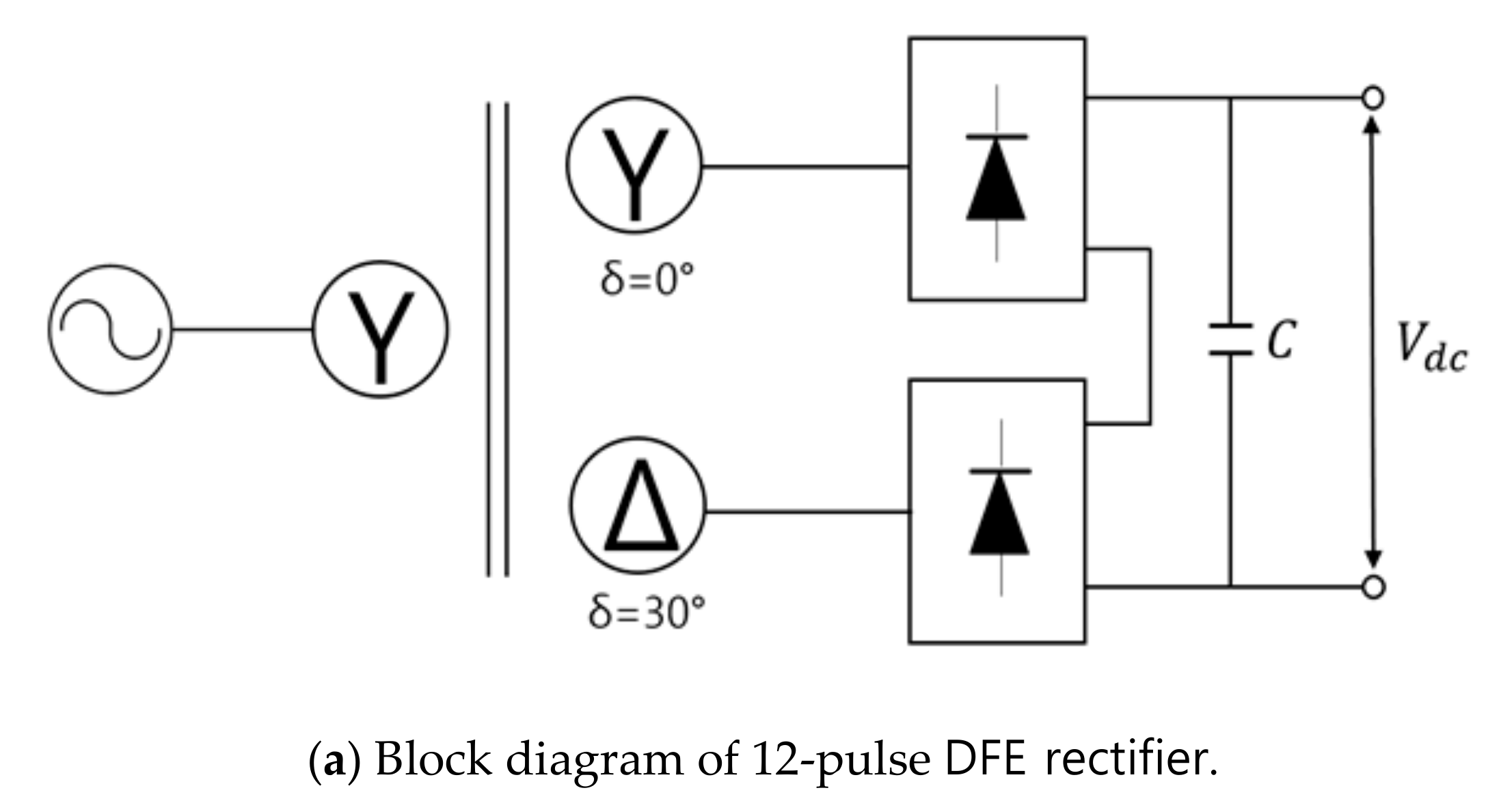
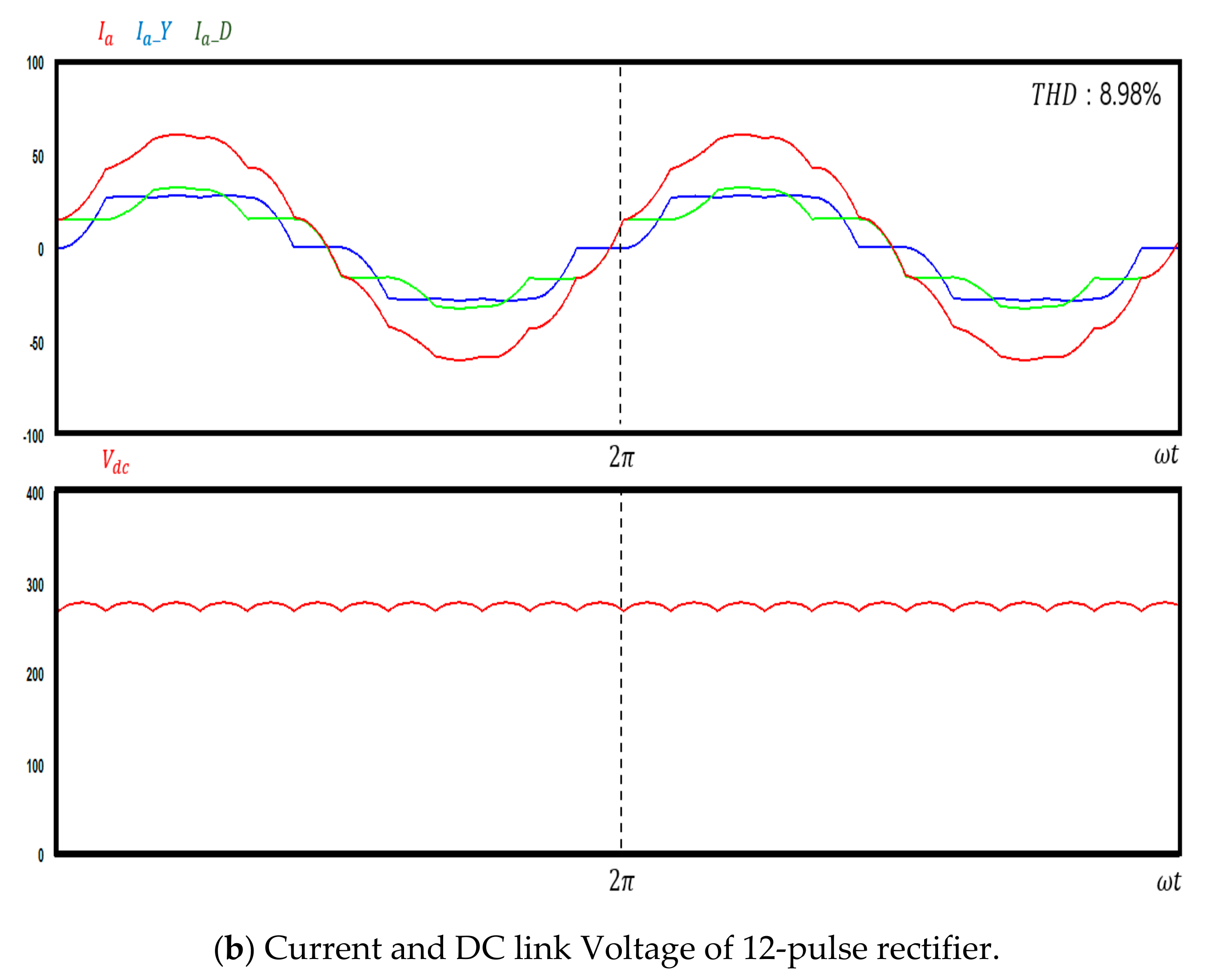
2.2.1. 12-Pulse Rectifier

One rectification method for improving the harmonic characteristics of the output of the power supply is to install a phase shifting transformer before the DFE rectifier to produce DC waveforms with 12-pulses in each cycle [15]. Figure 5 shows the block diagram of a DFE-style 12-pulse rectifier that uses a phase shifting transformer. The connections on the transformer’s secondary side consist of Y-Y and Y-D connections. The phase shift angle for creating 12-pulses per cycle is 30° between each phase, as indicated by Equation (1).
= e ab e AB = 30 °
where, is the phase shift angle, e a b is the line voltage of the primary side of the rectifier, and e A B is the line voltage of the secondary side of the rectifier.
Thus, in this case, for the 12-pulse DC waveforms that occur during one cycle, there is a 30° difference in the phases of the Y and D connections on the secondary side of the phase shifting transformer. In addition, there is a 30° difference in the phases of the 6-pulse DC waveforms generated by each unit, which produce a 12-pulse-per-cycle DC waveform in the DC link unit. In terms of the total harmonic distortion in the DC output waveform of the 12-pulse rectifier, the fifth order and seventh order harmonics are entirely eliminated, and only the harmonics that are 11th order and above remain. Thus, the rectifier effectively reduces the harmonic characteristics more effectively compared with a 6-pulse rectifier.

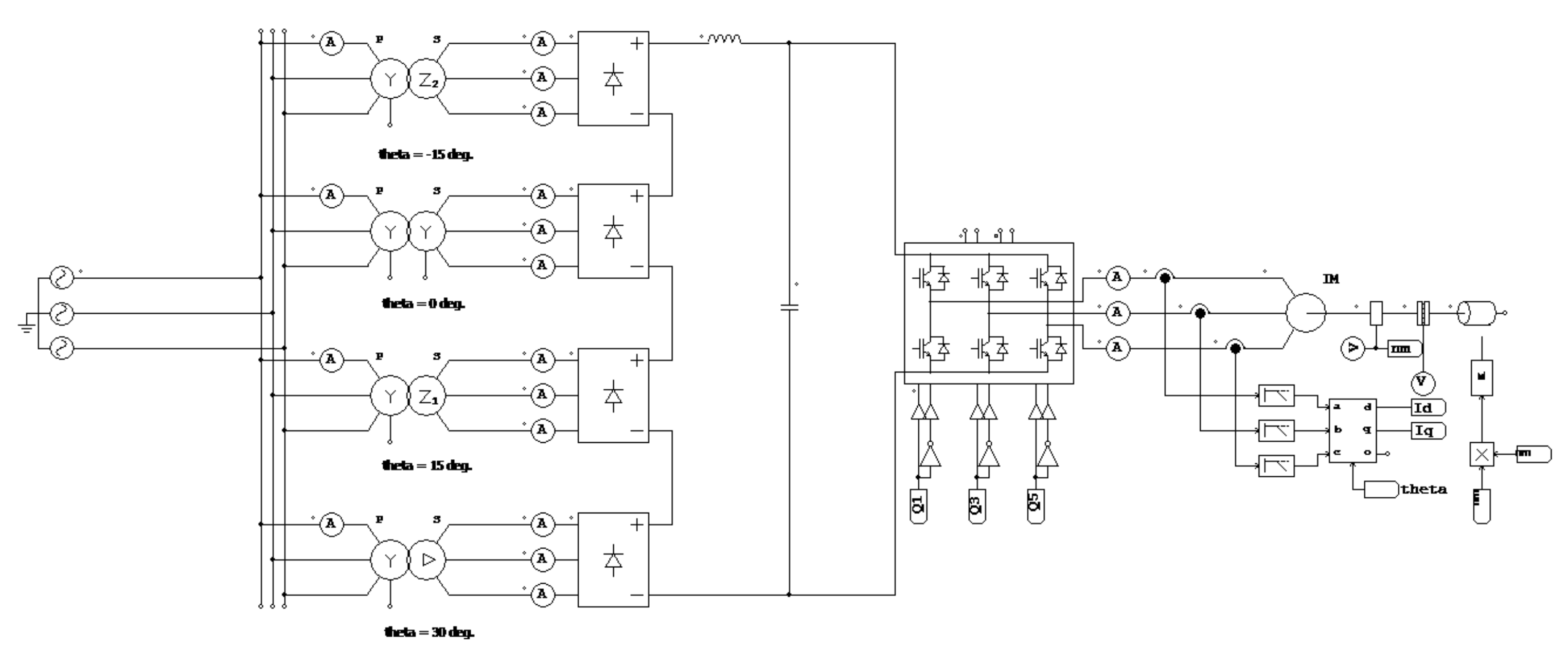
2.2.2. 24-Pulse Rectifier

A 24-pulse rectifier uses a zig-zag-shaped phase shifting transformer to create 24-pulse waveforms per cycle. Compared with the 12-pulse rectification method described above, this rectifier can produce better DC voltage waveforms and reduce harmonics more effectively. Figure 6 shows a block diagram of the 24-pulse rectifier. The phase shift angle of the phase shifting transformer, in this case, can be expressed via Equation (2) specified below, in particular, there is a phase difference of 15°.
= e a b e A B = 15 °
where, is the phase shift angle, e a b is the line voltage of the primary side, and e A B is the line voltage of the secondary side.
Considering the total harmonic distortion in the output waveforms generated by the 24-pulse rectifier, all lower-order harmonics below the 19th order are eliminated. Therefore, the 24-pulse rectifier has significantly better harmonic output characteristics than those of the 12-pulse rectifier. In addition, because the waveforms of the DC link unit include 24-pulses per cycle, this leads to a voltage waveform that is considerably similar to DC voltage.

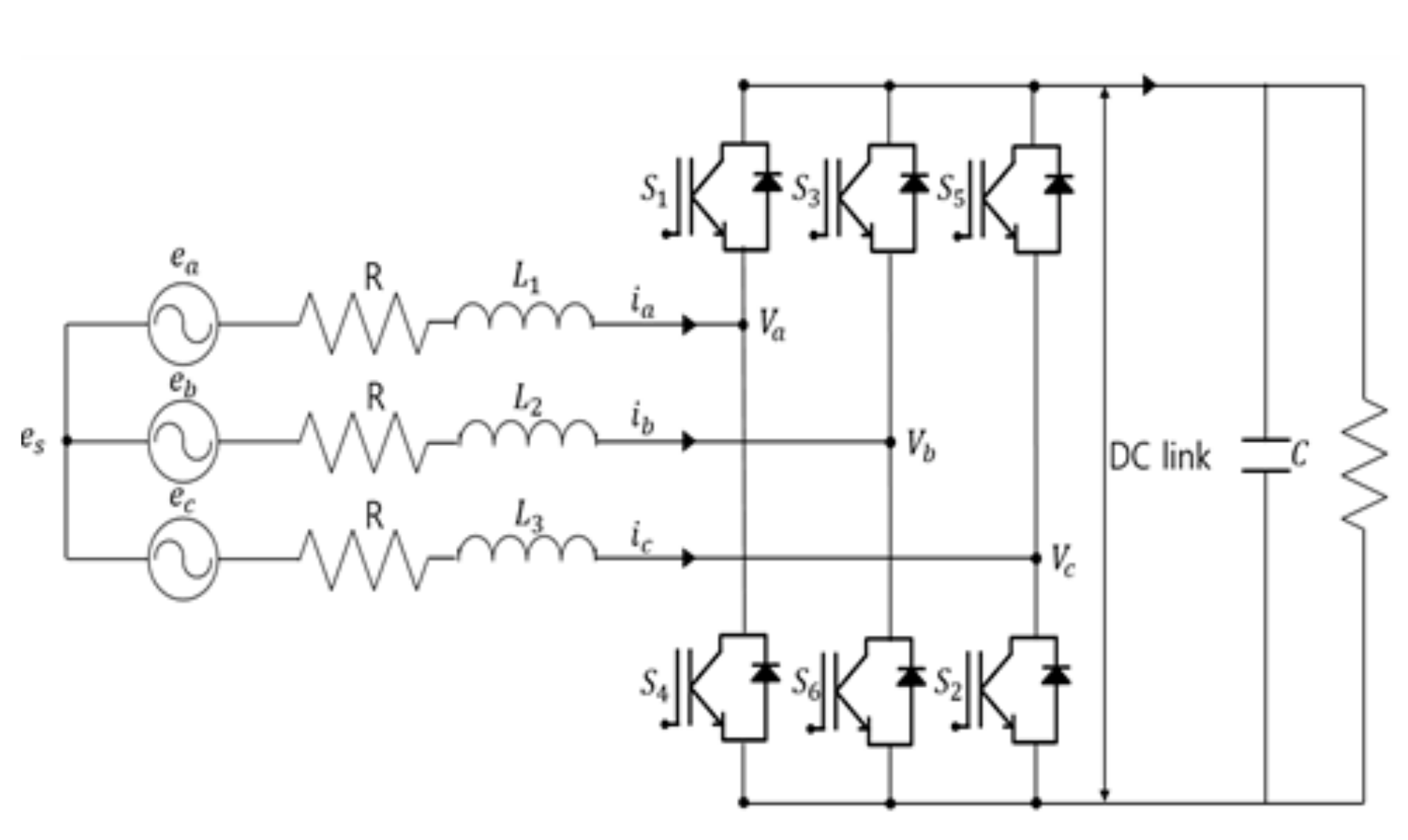
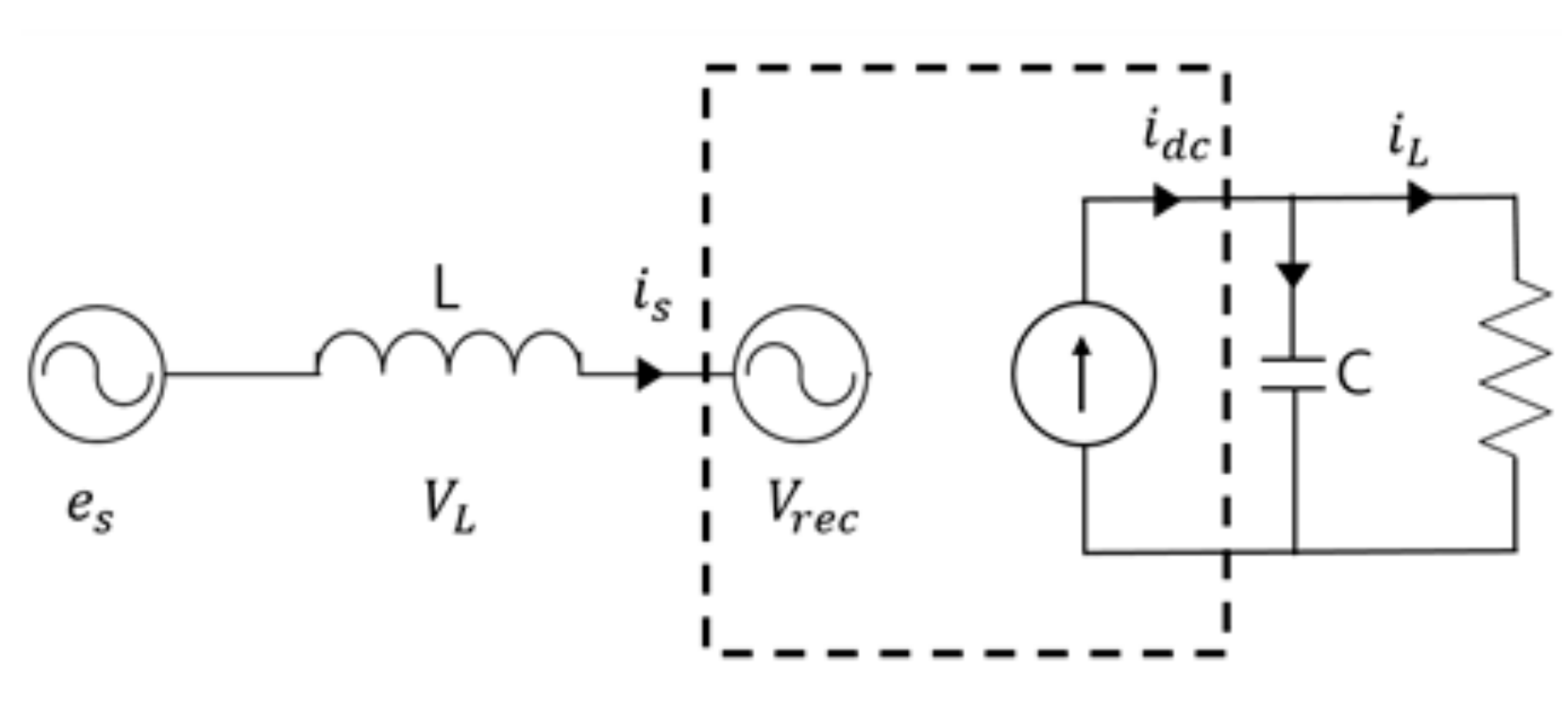
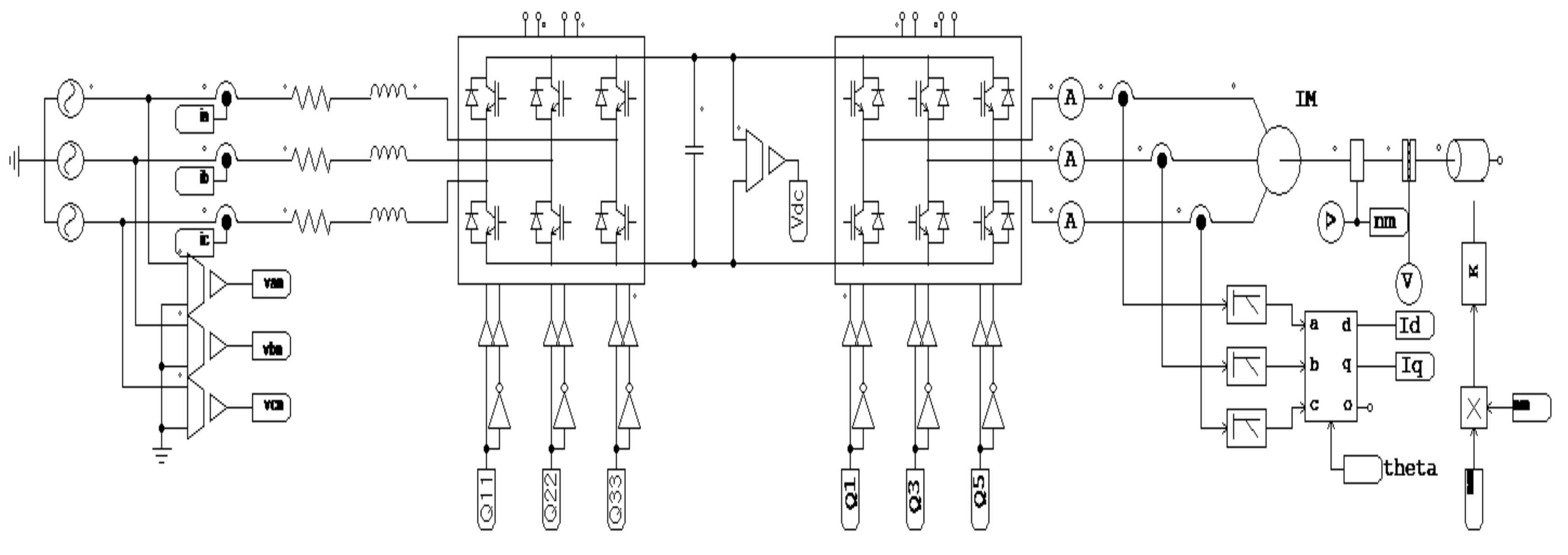
2.3. AFE Rectification Method in Large-Scale Electric Propulsion Systems

The AFE rectifier uses semiconductor-based technologies, such as Insulated Gate Bipolar Transistor (IGBTs), Integrated Gate Commutated Thyristor (IGCTs), and Metal Oxide Semiconductor Field Effect Transistor (MOSFETs), among others, which can turn power semiconductor elements off and on as required. Based on the control style of the semiconductor element, power conversion may be realized automatically. In particular, a fixed DC output voltage can be maintained even if the load changes. Thus far, AFE rectifiers have been primarily used in small- to mid-sized electric propulsion systems on ships owing to the limited capacities of the power semiconductor elements in these rectifiers [42].
The AFE rectifier must continuously measure the supply voltage to control the rectifier. As shown in Figure 7, the error of phase angle, which is crucial for the control of the rectifier, occurs momentarily due to the deterioration of the voltage quality, such as harmonics and noise included in the supply voltage.
As shown in Figure 8, the form of the AFE rectifier is the same as that of an inverter that converts DC current to AC current. The AFE rectifier consists of a total of three units and six power semiconductor switches. In addition, it includes an inductor that controls the input current of the power supply, as well as a capacitor that maintains a fixed DC output voltage.
Equation (3) is the voltage equation of the AFE rectifier.
e a b c = R i a b c + L d i a b c d t + V a b c
where, e a b c is the three-phase power supply voltage, i a b c is the phase current, and V a b c is the input side voltage of the rectifier.
The AFE rectifier controls the level and phase of the AC input current, i s , while performing the power conversion. The AFE rectifier must control the level of the voltage that is applied to the inductor on the input side. In particular, i s is controlled by controlling the input voltage of the rectifier, i.e., V r e c . Figure 9 shows the equivalent circuit for an AFE rectifier. The voltage V L that is applied to the inductor can be obtained using Equations (4) and (5).
e s = V R e c +   V L
V L =   ω L i s
where,   e s is the AC input to the power supply,   V L is the inductor voltage, and V r e c is the rectifier input voltage.
In order to control the AFE rectifier, it is necessary to find the d-q axis coordinate and current reference values that are in phase with the power supply voltage. To find these values, it is necessary to find the phase angle θ . In the conventional AFE rectifiers, the zero-crossing technique is used to find the phase angle θ for control. The zero-crossing technique involves measuring the power supply voltage and finding the 0 values that occur at each half cycle to estimate the current phase angle θ . Figure 10 shows the block diagram of a phase angle detector that uses the zero-crossing technique.
In particular, to find the phase angle, the moment when the power supply voltage changes from negative to positive can be set as the standard angle 0°, as depicted in Figure 11 Alternatively, the three-phase AC power supply values can be converted to a static coordinate system to find the phase angle directly, as given by Equation (6).
θ = tan 1 ( e α e β )
One advantage of the zero-crossing technique is that it can be used to find the phase angle in a simple manner. However, in some cases, some zero points are missed during the phase detection step, and consequently, its estimation speed is slow. Furthermore, another disadvantage of the zero-crossing technique is that estimation errors occur when noise due to harmonics or voltage notching occurs. Therefore, in this study, we created an AFE rectifier control circuit that uses the PLL method to accurately find the phase angle.

3. Large-Scale Electric Propulsion System Using an Improved AFE Rectifier

With the recent development of high-capacity power semiconductor elements, which can be used in large-scale electric propulsion systems, it has become theoretically possible for AFE rectifiers, which, thus far, were primarily used in small- to mid-sized electric propulsion systems on ships, to be used in large-scale electric propulsion systems.

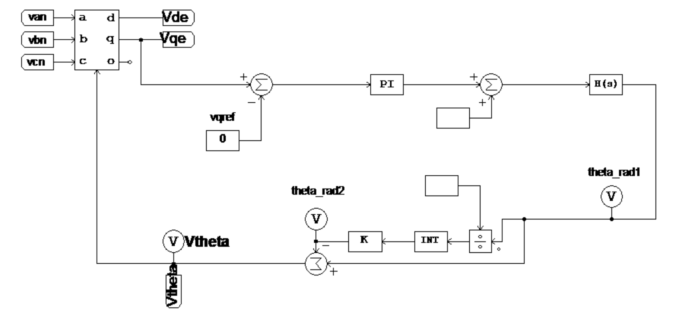
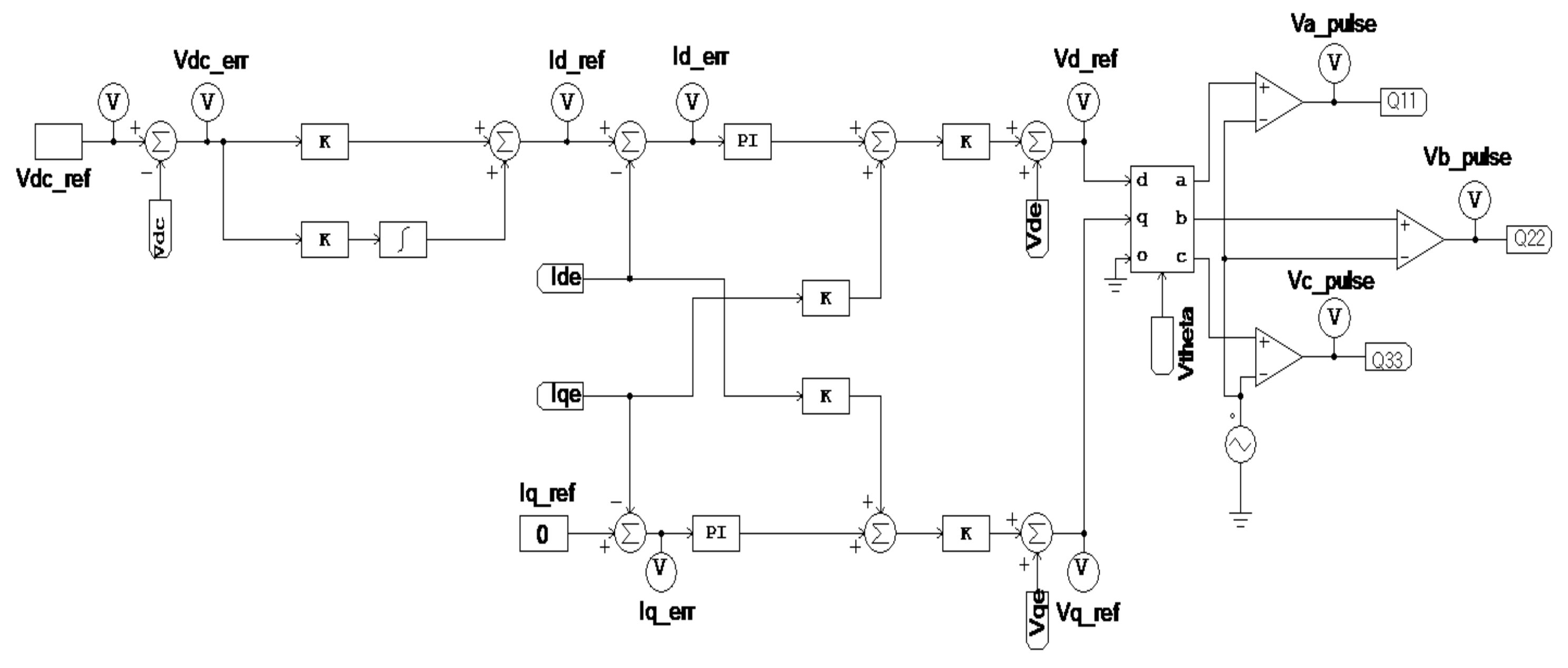
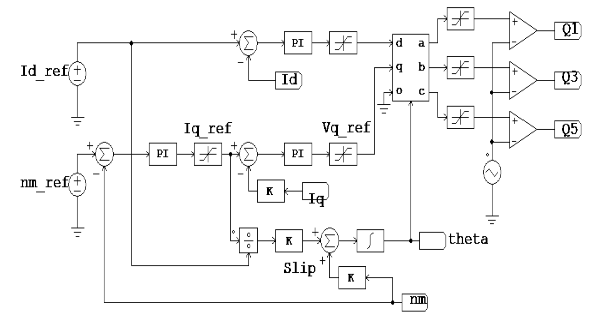
3.1. Improved AFE Rectifier Control

As can be deduced from the voltage equation of the AFE rectifier, i.e., Equation (3), the three-phase AC voltage and current values continuously change as time progresses. Therefore, it is difficult to ensure stable control over the rectifier. To control the rectifier in a simple, yet accurate manner, it is necessary to convert the coordinates of the three-phase AC power supply to a given standard axis in order to convert the voltage equation of the AFE rectifier to that with a stable DC value. In particular, by changing the coordinate system using such a conversion, the three-phase AC levels, which continuously change over time, can be converted to two DC values d-q, which are easy to control. These converted values can then be used to control the AFE rectifier [22,33].
Figure 12 shows the structure of a phase angle detector that uses the PLL method rather than the existing zero crossing technique to find the phase angle in an AFE rectifier. The PLL phase angle detector converts the voltage of the three-phase AC power supply to a value on the d-q axis in a synchronous rotating coordinate system. These values can then be used to find voltages e d , e q , which are DC voltages, and therefore, easy to control. In our study, e d is arbitrarily set to be the active power, while e q is set to be the reactive power. Then, the value of the reactive power e q can be controlled to ensure that it is 0.
Figure 13 shows the relationship between the q-axis voltage of the synchronous rotating coordinate system and voltage phase angle for controlling e q   so that it is zero. In Equation (7), P s is the active power supplied by the power supply.
P s = e a i a + e b i b + e c i c = 3 2 e d i d + e q i q = 3 2 e d i d
Thus, the power supply current is only affected by e d , which indicates the voltage value on the d-axis, whereas the current value on the q-axis current does not have any effect on it. Therefore, the supplied current can be given by P s = 3 2 e d i d . If the active power values are set on the d-axis, and the q-axis voltage is controlled so that it is 0, the actual phase angle θ becomes the same as the imaginary phase angle θ ^ as shown in Figure 13. Consequently, the phase angle θ can be accurately determined.
To find the actual phase angle θ , Equations (8) and (9) can first be solved by performing a coordinate conversion on the three-phase e a ,   e b , e c voltages of the AC power supply so that e a ,   e b , e c transform into voltages on the α β axis of the static coordinate system, as shown in Figure 14.
e α = E cos θ
e β = E sin θ
where, E is the peak value of the input AC phase voltage, and θ is the phase angle between a and the α -axis.
The values that have been converted to the static coordinate system with the α β axis are then converted to a synchronous rotating coordinate system with a d q axis using Equation (10). This is shown in Figure 15.
e d e q = cos θ sin θ sin θ cos θ e α e β
If the phase angle is the imaginary phase angle θ ^ rather than the actual phase angle θ , the voltage values on the d q axis of the synchronous rotating coordinate system can be expressed using Equation (11) as follows.
e d e q = cos θ ^ sin θ ^ sin θ ^ cos θ ^ e α e β .
Equation (11) can be represented as Equations (12) and (13) on simplification. Furthermore, Equations (8) and (9) can be used to obtain the voltage values in the static coordinate system using the actual phase value, and if they are substituted in Equations (12) and (13), the resulting equations are Equations (14) and (15), respectively.
e d = e α cos θ ^ + e β sin θ ^
e q = e α sin θ ^ + e β cos θ ^
e d = E cos θ cos θ ^ + sin θ sin θ ^ ) = E c o s ( θ θ ^
e q = E cos θ sin θ ^ + sin θ cos θ ^ ) = E s i n ( θ θ ^
where, θ is the actual phase value between the α and d axes, whereas θ ^ is the imaginary phase angle.
In Equation (15), if q -axis voltage value e q is adjusted to be 0, then θ = θ ^ , and Equations (16) and (17) can be solved. Consequently, the imaginary phase angle θ ^ can be controlled so that it matches the actual phase angle θ .
e d = E c o s θ θ ^ = E
e q = E s i n θ θ ^ = 0 .
If the three-phase input current is converted to the d q coordinate axis system based on the phase angle θ that is accurately obtained with the phase angle detector using the PLL control for the AFE rectifier, the DC equivalent values of the AC current can be obtained. Thus, it is possible to use a proportional integral controller to obtain an AFE rectifier with excellent control performance. Equations (18) and (19) represent the voltage equation in the synchronous rotating coordinate system with the d q axes.
e d = R i d + L d i d d t ω L i q + V d
e q = R i q + L d i q d t ω L i d + V q .
As is clear from Equations (18) and (19), there are speed electromotive and counter-electromotive force components that represent a disturbance in the current control. In particular, these components act as mutual interference components in the current control so that changes in the d-axis current affect the q-axis current and vice-versa. Therefore, in order to obtain good control characteristics when current control is performed in a synchronous rotating coordinate system, it is necessary to design a current controller that includes feed-forward compensation for the counter-electromotive and speed electromotive forces as indicated in Figure 16. If a feed-forward controller is included, the output voltage of a proportional integral current controller in a synchronous rotating coordinate system can be expressed as Equations (20) and (21).
e d * = e d f b * + e d f f *
e q * = e q f b * + e q f f *

3.2. Controlling the Propulsion Motor Speed of a Large-Scale Electric Propulsion System Using the Improved AFE Rectifier

In this study, we used an indirect vector control technique to control the propulsion motor speed of a large-scale electric propulsion system. The indirect vector control technique uses flux current, torque current, and electric motor constant in the synchronous rotating coordinate system to calculate the slip reference angular speed. The integral value of this added to the rotor speed is considered as the flux angle. For high-performance torque and flux control, the stator current that is provided to the motor is divided into different components that match each of the components that are orthogonal to the standard flux [38,43].
In Figure 17, the α β axis is fixed to the stator, while the d–q axis rotates at the synchronous angular speed ω θ . The rotating axis is matched to the d axis, while the slip angle ( θ s l ) to the rotor axis is maintained as the axis rotates. Therefore, the stator current supplied to the electric motor is divided into the flux component current i d s and torque component current i q s , which can be used to perform high-quality torque and flux control.
In the case of rotator flux-based indirect vector control, the rotator flux is controlled to ensure that it only exists as a d-axis component. Therefore, Equation (22) is valid.
λ q r = ρ λ q r = 0
As can be deduced from Equation (23), the torque is proportional to i q s . Therefore, i q s can be considered as the torque component current. Furthermore, when flux control is constant, the rotator flux can be controlled via i d s . Therefore, i d s can be considered as the flux component.
T e = 3 2 P 2 L m L r λ d r i q s
Thus, when i d s is constant, the slip relational equation can be expressed as Equation (24).
ω s l = R r L r i q s i d s
The position of the rotator flux can be obtained as the integral value of the sum of the electric motor speed and slip reference angular speed, as shown in Equation (25) below.
θ e = ω r + ω s l d t

4. Methodology

In the present study, several different large-scale electric propulsion systems were modeled using the DFE rectifier, phase shifting transformer, conventional AFE rectifier, and improved AFE rectifier. A comparative analysis was performed on the operating characteristic results that were obtained for the large-scale electric propulsion system with the improved AFE rectifier and conventional DFE and AFE rectifiers in Figure 18. The modeled large-scale electric propulsion system is the same as the electric propulsion systems that are installed and used in current LNG tankers. The propulsion motor parameters are listed in Table 3. Figure 19 is a graph showing the oscillation of the output voltage of the generator due to the load variation during the actual operation of the ship. Thus, in order to verify the effectiveness of the proposed AFE rectifier, an arbitrary waveform was inserted into the output of the generator during the simulation.
To compare the characteristics of the large-scale electric propulsion systems based on their rectification method, systems were developed that used the improved AFE rectifier in Figure 20 as well as one that used an existing 24-pulse rectifier in Figure 21 with a phase shifting transformer. The improved AFE rectifier and power semiconductor in the inverter used the same IGBT module. The primary specifications of the power semiconductor are listed in Table 4 [44].
In order to verify the robustness of the proposed AFE rectifier control, an irregular waveform was arbitrarily generated by inserting instantaneous zero-point noise, harmonics, etc. in the output power voltage of the generator during the simulation.
In Figure 20, the phase angle that is needed to control the proposed improved AFE rectifier was obtained using a phase angle detector with a PLL controller, as shown in Figure 22. The q-axis voltage, which is the reactive power component that is converted to a synchronous rotating coordinate system, was controlled always to be 0, so that the phase angle would match the actual phase angle during phase angle determination.
The current controller for the AFE rectifier is shown in Figure 23. In particular, the output of the DC link was compared with the reference voltage value in real time using the current controller used for controlling the AFE rectifier. Furthermore, the error was controlled by the proportional integral controller, and the feed-forward compensation technique was used to remove the mutual interference components of the counter electromotive and speed electromotive forces.
In addition, the inverter used the indirect vector technique to control the speed and torque of the propulsion motor. This indirect vector control is depicted in Figure 24. Simulations of the modeled circuits were performed to compare speed response characteristics of the propulsion motor, DC output voltage waveforms of the DC link, input side harmonic output characteristics of the power supply, and heat loss in the inverter switching element, among others based on the changes in the rectification method of the simulated large-scale electric propulsion system.

5. Analysis Simulations of the Operating Characteristics of Large-Scale Electric Propulsion Systems According to Rectification Method

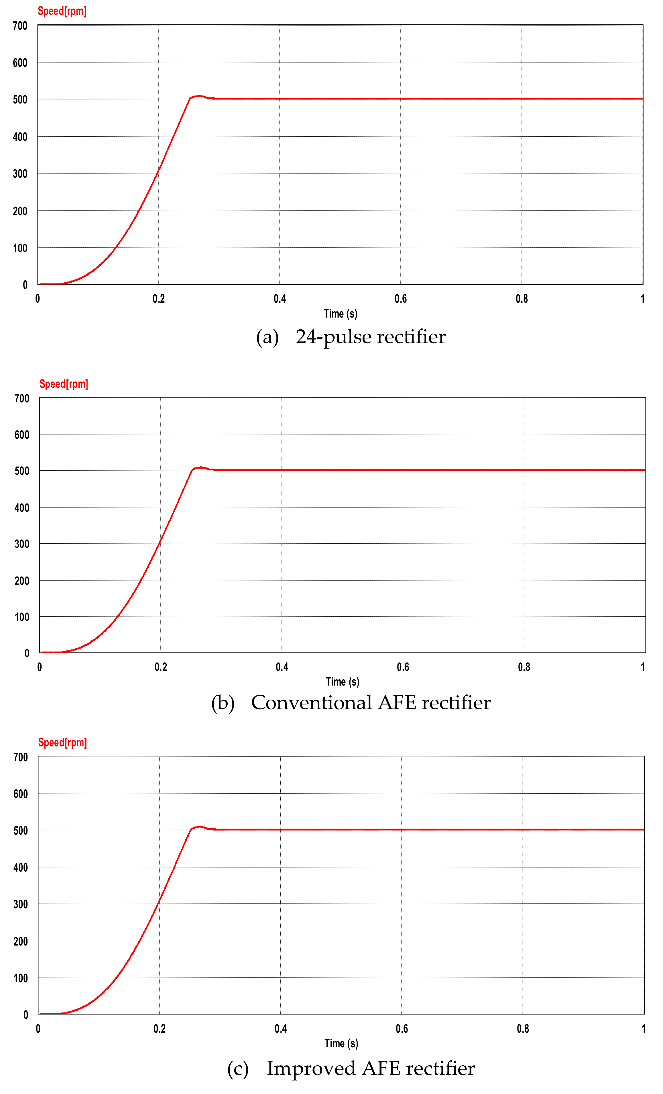
5.1. Speed Response Characteristics of the Propulsion Motor

Figure 25 shows the results of the simulation on the characteristics of the propulsion motor’s response to step speed reference values. The standard speed value was set as 500 rpm. Based on these results, it can be observed that the conventional AFE rectifier, 24-pulse rectifier, and improved AFE rectifier all showed relatively good speed response characteristics to the reference value.

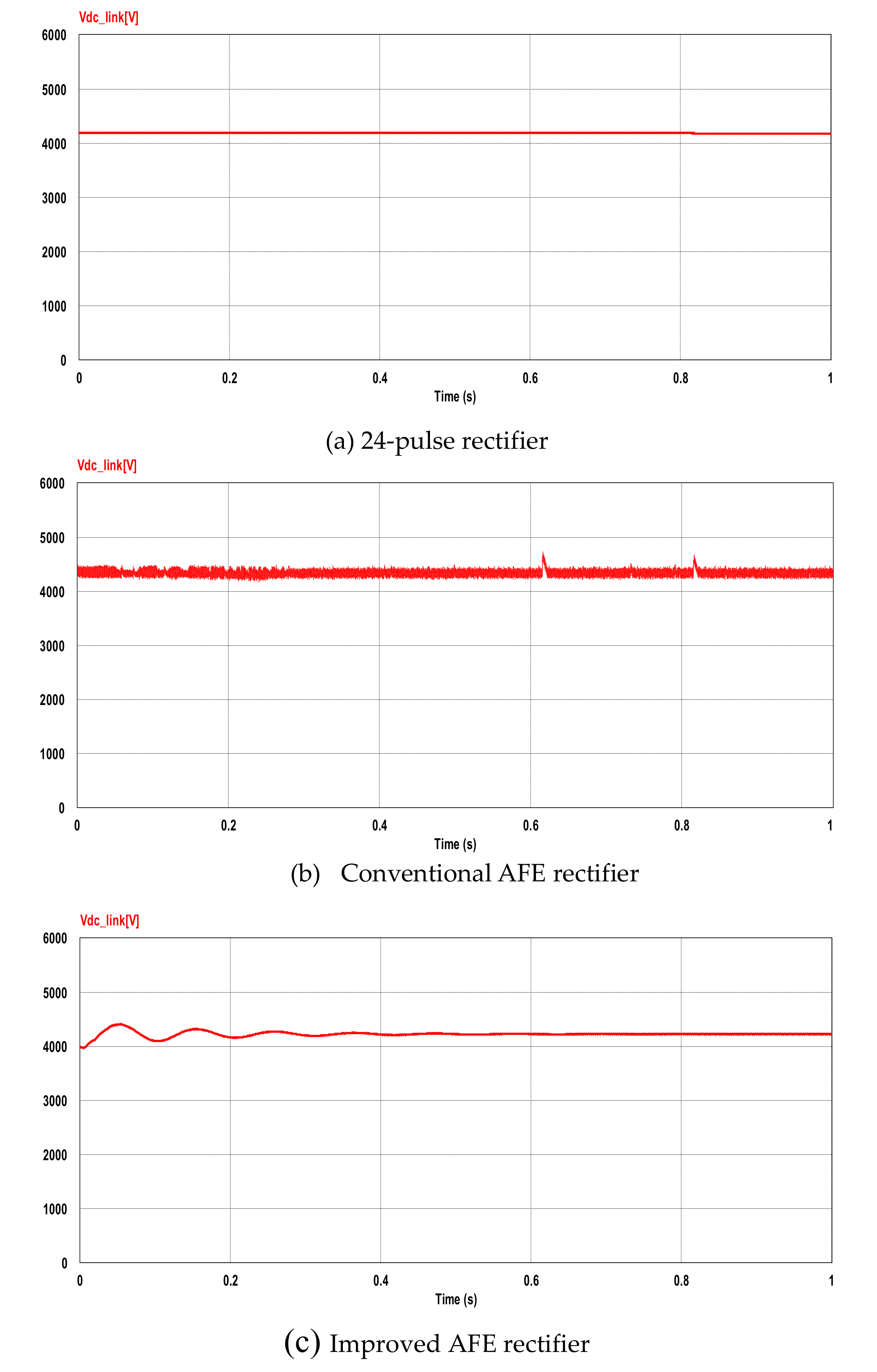
5.2. Comparison of the DC Output Voltage Waveform in the DC Link

Figure 26 shows the DC output voltage in the DC link when different rectifiers are used. The 24-pulse rectifier, which uses the phase shifting transformer, had the best response characteristics to the reference DC voltage. Nevertheless, the improved AFE rectifier maintained the DC output voltage in a more stable state than the conventional AFE rectifier.

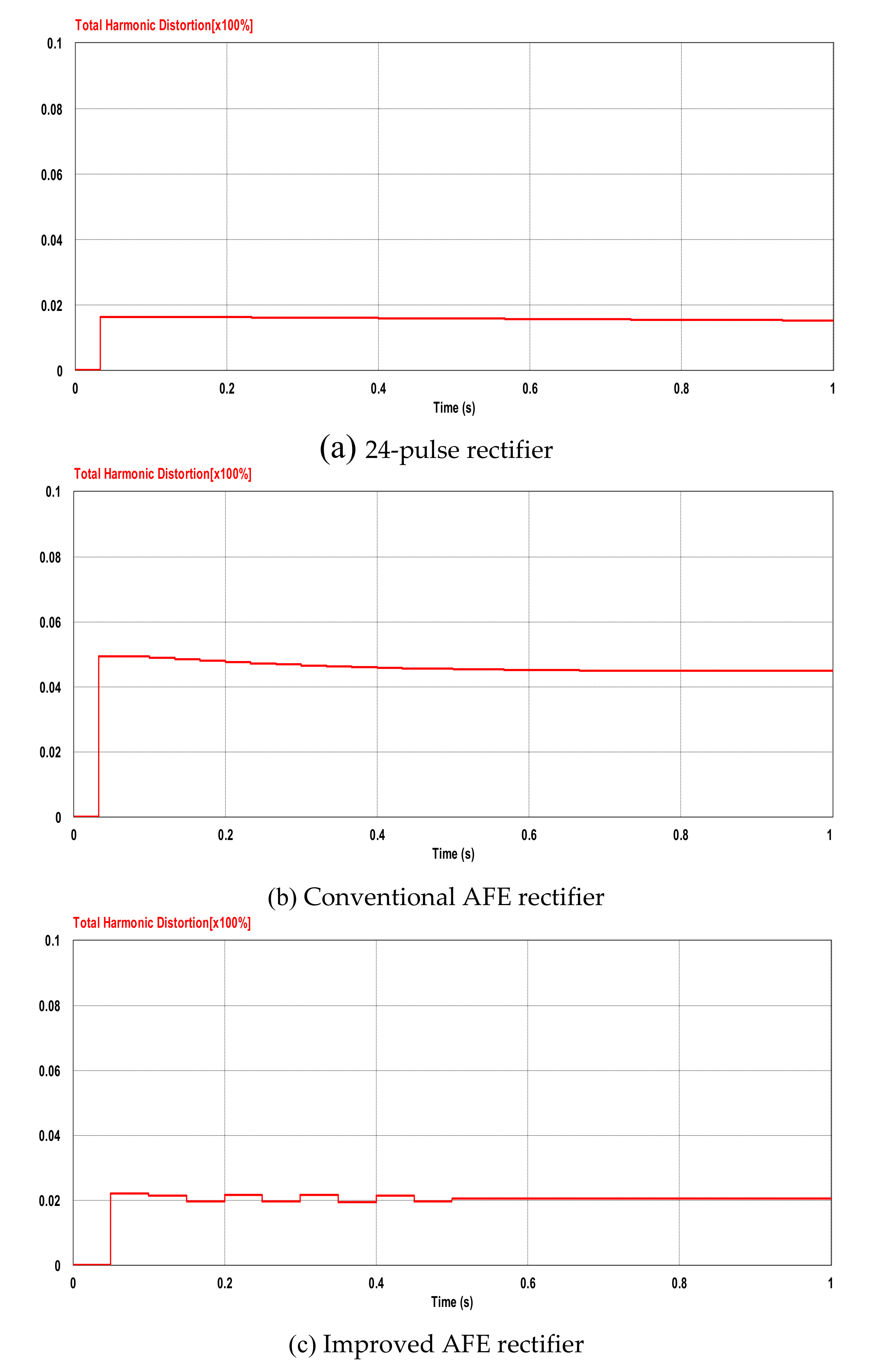
5.3. Comparison of the Total Harmonic Distortion in the Voltage of the Power Source

Figure 27 shows the results of the simulation for the total harmonic distortion in the power supply at the output side. The estimated values for the electric propulsion system that used the improved AFE rectifier were about 2% better than the case wherein the conventional AFE rectifier was used. Similar results were obtained for the 24-pulse rectifier. These values satisfied the recommendation for total harmonic distortion that is included in the IEEE Standard 519-2014 [45], which specifies a total harmonic distortion of 8% in power generators under 1 kV.

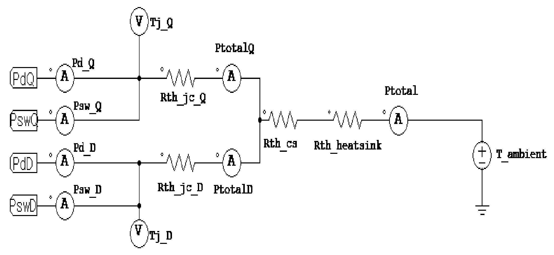
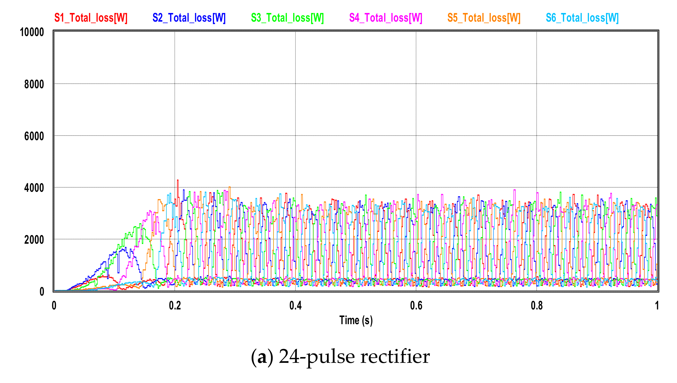
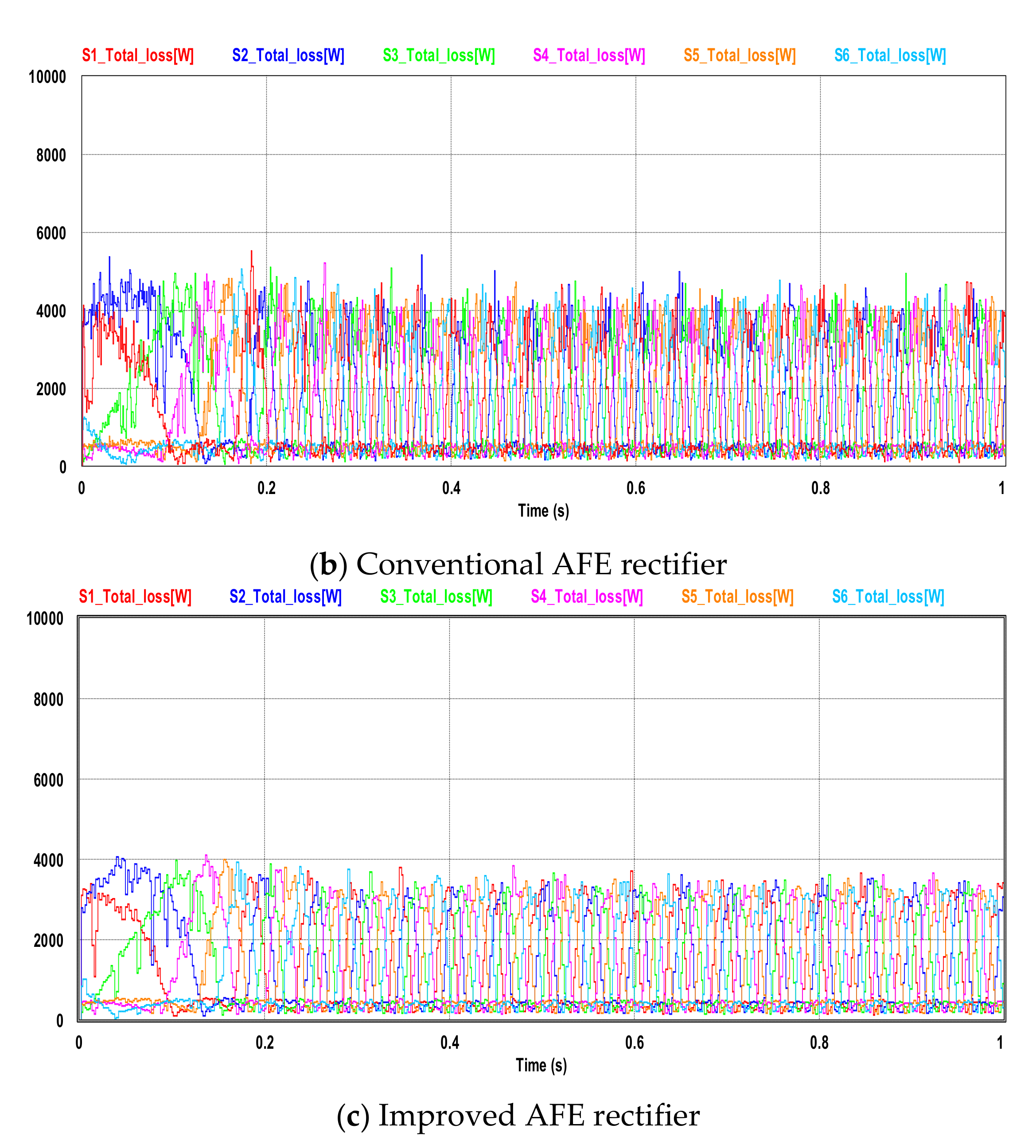
5.4. Comparison of the Heat Loss in the Inverter Switching Element

The inverter’s IGBT module consists of the IGBT element and diode. Loss during power conversion can be categorized into switching loss and conduction loss in the IGBT element as well as switching loss and conduction loss in the diode element. The simulation estimated the power loss and heat loss in the inverter module’s diode and IGBT element. The equation for obtaining conduction loss and switching loss is as follows. Figure 28 shows the block diagram of the apparatus used to record heat loss.
Conduction losses:
P c o n d _ Q = V c e s a t × I c × D
Switching losses:
Turn   on   P s w _ Q _ o n = E o n × f × V c c ÷ V c c _ d a t a s h e e t
Turn   off   P s w _ Q _ o f f = E o f f × f × V c c ÷ V c c _ d a t a s h e e t
where, V c e s a t is the transistor collector–emitter saturation voltage, I c is the collector current, D is conducting duty cycle, E o n is the transistor turn-on energy losses, E o f f is the transistor turn-off energy losses, f is the frequency, and V c c is the actual dc bus voltage.
Figure 29 shows the results of our simulations to estimate the sum of the switching and conduction losses of the diode in the inverter of a large-scale electric propulsion system using the conventional AFE rectifier, 24-pulse rectifier, and improved AFE rectifier. Table 5 lists the average of these results. It is clear from these analysis results that the system with the improved AFE rectifier shows lower switching losses than the one with the 24-pulse rectifier.

6. Conclusions

Relatively good propulsion motor speed response results were obtained for the large-scale electric propulsion systems that were modeled using each of the rectification methods. However, the large-scale electric propulsion system that used the improved AFE rectifier was able to accurately detect the phase angle of the power supply voltage using a PLL control circuit. Therefore, it was able to obtain a more stable DC link voltage output and reduced number of harmonics in the input power supply side compared with the conventional AFE rectifier. Furthermore, the improved rectifier showed similar output performance as the 24-pulse DFE rectifier, which uses a phase shifting transformer. In addition, from the simulation results, it was observed that when the proposed AFE rectifier is used, the DC output performance of the DC link in the rectifier was improved. Consequently, the switching loss of the power semiconductor of the inverter used for controlling the speed of the propulsion motor was similar to that of the 24-pulse rectifier.
So far, large-sized electric propulsion vessels have adopted the same high-power drive system of the shore, but the use of phase shifting transformers with DFE rectifiers in a limited space and heavy weight has several disadvantages. In this study, an improved AFE rectifier with superior performance compared to the 24-pulse rectifier was applied. Research findings revealed that the proposed system would mitigate the complexity of the electric converting system by reducing the number of the rectifiers to be fitted. Therefore, the optimized spatial arrangement in the engine room could contribute to increasing the cargo loading efficiency of the vessel.
Based on these simulation results, it was confirmed that it can be more effective for a large-scale electric propulsion system to use an AFE rectifier that can turn a power semiconductor switch on and off, rather than using an existing DFE rectifier employing a phase switching transformer.

Author Contributions

Conceptualization, J.K and K.Y.; Methodology, J.S., K.Y. and H.J.; Formal analysis, H.J.; Software, K.Y. and H.J.; Writing-original draft preparation, H.J.; Writing-review and editing, K.Y.

Funding

This research received no external funding.

Acknowledgments

We thank our colleagues from Seoung Hwan Kim who provided insight and expertise that greatly assisted the research, although they may not agree with all of the conclusions of this paper. In addition, they are indebted towards Prof. Kim for his assistance on setting-up the simulations in the PSIM environment.

Conflicts of Interest

The authors declare no conflict of interest.

References

  1. International Maritime Organization. Marine Environment Protection Committee 72nd Session. Available online: http://www.imo.org/en/MediaCentre/MeetingSummaries/MEPC/Pages/MEPC-72nd-session.aspx (accessed on 13 April 2018).
  2. International Maritime Organization. Marine Environment Protection Committee. Available online: http://www.imo.org/en/MediaCentre/HotTopics/Pages/Sulphur-2020.aspx (accessed on 23 June 2016).
  3. ABB Group. System Project Guide for Passenger. Available online: https://library.e.abb.com/public/608df0ae42ea2ce8c1257abd004ff506/ABB_System_Project_Guide_Passenger_Vessels.pdf (accessed on 1 February 2011).
  4. Hansen, J.F.; Wendt, F. History and State of the Art in Commercial Electric Ship Propulsion, Integrated Power Systems, and Future Trends. Proc. IEEE 2015, 103, 2229–2242. [Google Scholar] [CrossRef]
  5. McCoy, T.J. Trends in Ship Electric Propulsion. In Proceedings of the IEEE Power Engineering Society Summer Meeting, Chicago, IL, USA, 21–25 July 2002; pp. 343–346. [Google Scholar]
  6. Skjong, E.; Cunningham, J.; Johansen, T.A.; Rodskar, E.; Molinas, M.; Volden, R. Past, Present, and Future Challenges of the Marine Vessel’s Electrical Power System. IEEE Trans. Transp. Electrif. 2016, 2, 522–537. [Google Scholar] [CrossRef]
  7. Vasquez, C.A. Methodology to Select the Electric Propulsion System for Platform Supply Vessels. Master’s Thesis, Universidade de Sao Paulo, Sao Paulo, Brazil, 2014. [Google Scholar]
  8. Clarksons Research. Available online: https://clarksonsresearch.wordpress.com/tag/propulsion/ (accessed on 31 March 2017).
  9. Ajioka, Y. Electric Propulsion Systems for Ships. Hitachi Rev. 2013, 62, 231–232. [Google Scholar]
  10. Ådnanes, A.K. Maritime Electrical Installations and Diesel Electric Propulsion; ABB AS: Oslo, Norway, 2003; 86. [Google Scholar]
  11. McCoy, T.J.; Amy, J.V. The State-of-the-Art of Integrated Electric Power and Propulsion Systems and Technologies on Ships. In Proceedings of the IEEE Electric Ship Technologies Symposium ESTS, Baltimore, MA, USA, 20–22 April 2009; pp. 340–344. [Google Scholar]
  12. Hoevenaars, T.; Evans, I.C.; Lawson, A. New Marine Harmonic Standards. IEEE Ind. Appl. Mag. 2010, 16, 16–25. [Google Scholar] [CrossRef]
  13. Verboomen, J.; Van Hertem, D.; Schavemaker, P.H.; Kling, W.L.; Belmans, R. Phase shifting transformers: Principles and applications. In Proceedings of the 2005 International Conference on Future Power Systems, Amsterdam, The Netherlands, 18 November 2005. [Google Scholar]
  14. Kim, J.S.; Choi, J.H.; Yoon, K.K.; Seo, D.H. Harmonic Reduction of Electric Propulsion Ship using New Rectification Scheme. J. Korean Inst. Inf. Commun. Eng. 2012, 16, 2230–2236. [Google Scholar] [CrossRef] [Green Version]
  15. Kim, J.S. Harmonic Reduction of Electric Propulsion Ship by Multipulse Drive. J. Korean Inst. Marit. Inf. Commun. Sci. 2010, 15, 425–431. [Google Scholar]
  16. Sun, J.; Bing, Z.; Karimi, K.J. Input Impedance Modeling of Multipulse Rectifiers by Harmonic Linearization. IEEE Trans. Power Electron. 2009, 24, 2812–2820. [Google Scholar]
  17. Akagi, H.; Isozaki, K. A Hybrid Active Filter for a Three-Phase 12-Pulse Diode Rectifier Used as the Front End of a Medium-Voltage Motor Drive. IEEE Trans. Power Electron. 2012, 27, 69–77. [Google Scholar] [CrossRef]
  18. Kamath, G.R.; Runyan, B.; Wood, R. A Compact Autotransformer Based 12-Pulse Rectifier Circuit. In Proceedings of the 27th Annual Conference of the IEEE Industrial Electronics Society, Denver, CO, USA, 29 November–2 December 2001; pp. 1344–1349. [Google Scholar]
  19. Skibinski, G.L.; Guskov, N.; Zhou, D. Cost Effective Multi-Pulse Transformer Solutions for Harmonic Mitigation in AC Drives. In Proceedings of the 38th IAS Annual Meeting on Conference Record of the Industry Applications Conference, Salt Lake City, UT, USA, 12–16 October 2003; pp. 1488–1497. [Google Scholar]
  20. Wen, J.; Qin, H.; Wang, S.; Zhou, B. Basic Connections and Strategies of Isolated Phase-Shifting Transformers for Multipulse Rectifiers: A Review. In Proceedings of the 2012 Asia-Pacific Symposium on Electromagnetic Compatibility APEMC 2012, Singapore, 21–24 May 2012; pp. 105–108. [Google Scholar]
  21. Kim, S.Y.; Choe, S.; Ko, S.; Kim, S.; Sul, S.K. Electric Propulsion Naval Ships with Energy Storage Modules through AFE Converters. J. Power Electron. 2014, 14, 402–412. [Google Scholar] [CrossRef] [Green Version]
  22. Kim, S.Y.; Cho, B.G.; Sul, S.K. Consideration of Active-Front-End Rectifier for Electric Propulsion Navy Ship. In Proceedings of the 2013 IEEE Energy Conversion Congress & Expo, Denver, CO, USA, 15–19 September 2013; pp. 13–19. [Google Scholar]
  23. Applied Materials. Available online: http://www.appliedmaterials.com/nanochip/nanochip-fab-solutions/december-2013/power-struggle (accessed on 8 March 2013).
  24. Gupta, A.; Rajev, T.; Sachin, M. Review on Zero Crossing Detector. India IJECT J. 2012, 7109, 366–368. [Google Scholar]
  25. Irmak, E.; Colak, I.; Kaplan, O.; Guler, N. Design and Application of a Novel Zero-Crossing Detector Circuit. In Proceedings of the International Conference on Power Engineering Energy and Electrical Drives, Malaga, Spain, 11–13 May 2011; pp. 1–4. [Google Scholar]
  26. Vainio, O.; Ovaska, S.J. Noise Reduction in Zero Crossing Detection by Predictive Digital Filtering. IEEE Trans. Ind. Electron. 1995, 42, 58–62. [Google Scholar] [CrossRef]
  27. Wall, R.W. Simple Methods for Detecting Zero Crossing. In Proceedings of the 29th Annual Conference of the IEEE Industrial Electronics Society (IEEE Cat. No.03CH37468), Roanoke, VA, USA, 2–6 November 2003; Volume 3, pp. 2477–2481. [Google Scholar]
  28. Parvez, M.; Mekhilef, S.; Tan, N.M.L.; Akagi, H. An Improved Active-Front-End Rectifier Using Model Predictive Control. In Proceedings of the 2015 IEEE Applied Power Electronics Conference and Exposition (APEC), Charlotte, NC, USA, 15–19 March 2015; pp. 122–127. [Google Scholar]
  29. Chomat, M. Operation of Active Front-End Rectifier in Electric Drive under Unbalanced Voltage Supply. Electr. Mach. Drives 2012, 10, 195–216. [Google Scholar]
  30. Chung, S.K. Phase-Locked Loop for Grid-Connected Three-Phase Power Conversion Systems. IEE Proc. Electr. Power Appl. 2000, 147, 213–219. [Google Scholar] [CrossRef]
  31. Trivedi, M.S.; Mujumdar, U.B. Study and Simulation of Parks Transform PLL for robust single phase grid connected system. Int. J. Recent Innov. Trends Comput. Commun. 2015, 3, 149–152. [Google Scholar]
  32. Guo, X.Q.; Wu, W.Y.; Gu, H.R. Phase Locked Loop and Synchronization Methods for Grid- Interfaced Converters: A Review. Prz. Elektrotechniczny 2011, 87, 182–187. [Google Scholar]
  33. Salamah, A.M.; Finney, S.J.; Willians, B.W. Three-phase Phase-locked loop for Distorted Utilities. IET Electr. Power Appl. 2001, 67, 263–270. [Google Scholar]
  34. Wiechmann, E.P.; Aqueveque, P.; Burgos, R.; Rodriguez, J. On the Efficiency of Voltage Source and Current Source Inverters for High-Power Drives. IEEE Trans. Ind. Electron. 2008, 55, 1771–1782. [Google Scholar] [CrossRef]
  35. Wu, B. High-Power Converters and AC Drives, 2nd ed.; Wiley: Hoboken, NJ, USA, 2006; pp. 251–316. [Google Scholar]
  36. Al-Falahi, M.D.A.; Tarasiuk, T.; Jayasinghe, S.G.; Jin, Z.; Enshaei, H.; Guerrero, J.M. Ac Ship Microgrids: Control and Power Management Optimization. Energies 2018, 11, 1458. [Google Scholar] [CrossRef]
  37. Zahedi, B.; Norum, L.E. Modeling and Simulation of All-Electric Ships with Low-Voltage DC Hybrid Power Systems. IEEE Trans. Power Electron. 2013, 28, 4525–4537. [Google Scholar] [CrossRef]
  38. Thantirige, K.; Rathore, A.K.; Panda, S.K.; Jayasignhe, G.; Zagrodnik, M.A.; Gupta, A.K. Medium Voltage Multilevel Converters for Ship Electric Propulsion Drives. In Proceedings of the 2015 International Conference on Electrical Systems for Aircraft, Railway, Ship Propulsion and Road Vehicles (ESARS), Archen, Germany, 3–5 March 2015. [Google Scholar]
  39. Sofras, E.; Prousalidis, J. Developing a New Methodology for Evaluating Diesel—Electric Propulsion. J. Mar. Eng. Technol. 2014, 13, 63–92. [Google Scholar] [CrossRef]
  40. ABB GROUP. Available online: http://pdf.nauticexpo.com/pdf/abb-marine/abb-lngcarrier-brochure-final/30709-44457.html (accessed on 1 May 2009).
  41. Prousalidis, J.; Antonopoulos, G.; Mouzakis, P.; Sofras, E. On Resolving Reactive Power Problems in Ship Electrical Energy Systems. J. Mar. Eng. Technol. 2015, 14, 124–136. [Google Scholar] [CrossRef]
  42. Kumar, D.; Zare, F.; Ghosh, A. DC Microgrid Technology: System Architectures, AC Grid Interfaces, Grounding Schemes, Power Quality, Communication Networks, Applications, and Standardizations Aspects. IEEE Access 2017, 5, 12230–12256. [Google Scholar] [CrossRef]
  43. Sul, S.K. Control of Electric Machine Drives Systems; Hongleung Science: Seoul, Korea, 2016; pp. 306–326. [Google Scholar]
  44. ABB. ABB HiPak IGBT Module 5SNA 1200G450350 Datasheet. Available online: https://new.abb.com/semiconductors/integrated-gate-commutated-thyristors- (accessed on 8 January 2019).
  45. IEEE. IEEE Std 519-2014 IEEE Recommended Practice and Requirements for Harmonic Control in Electric Power Systems; IEEE: New York, NY, USA, 2014; pp. 5–9. [Google Scholar]
Figure 1. Annual ship newbuilding contracts.
Jmse 07 00168 g001
Figure 2. Schematic diagram of a large-scale electric propulsion system.
Jmse 07 00168 g002
Figure 3. Typical configuration for a twin skeg electric propulsion ship.
Jmse 07 00168 g003
Figure 4. Phase shifting transformer installed on large-scale electric propulsion system.
Jmse 07 00168 g004
Figure 5. Block diagram and Waveforms of a DFE-style 12-pulse rectifier.
Jmse 07 00168 g005aJmse 07 00168 g005b
Figure 6. Block diagram and Waveforms of a 24-pulse rectifier.
Jmse 07 00168 g006
Figure 7. An example of phase angle error.
Jmse 07 00168 g007
Figure 8. Block diagram of an AFE rectifier.
Jmse 07 00168 g008
Figure 9. Equivalent circuit of the AFE equivalent circuit.
Jmse 07 00168 g009
Figure 10. Phase angle detector using the zero-crossing technique.
Jmse 07 00168 g010
Figure 11. Relationship between the power supply voltage and phase angle in the case of the zero-crossing technique.
Jmse 07 00168 g011
Figure 12. Block diagram of a phase detector using the PLL method.
Jmse 07 00168 g012
Figure 13. Imaginary phase angle, which is the same as the actual phase angle.
Jmse 07 00168 g013
Figure 14. Conversion to input voltage’s coordinate axis.
Jmse 07 00168 g014
Figure 15. Coordinate conversion to a synchronous rotating coordinate system.
Jmse 07 00168 g015
Figure 16. Current controller in the AFE rectifier that compensates for the counter-electromotive force.
Jmse 07 00168 g016
Figure 17. Indirect vector control.
Jmse 07 00168 g017
Figure 18. Flowchart of comparison analysis with each rectifier.
Jmse 07 00168 g018
Figure 19. The hunting of the output voltage of generator due to load variation in the actual operation of the ship.
Jmse 07 00168 g019
Figure 20. Overall block diagram of the electric propulsion system with the improved AFE rectifier.
Jmse 07 00168 g020
Figure 21. Overall block diagram of the electric propulsion system with a 24-pulse rectifier that employs a phase shifting transformer.
Jmse 07 00168 g021
Figure 22. Phase angle detector with a PLL controller.
Jmse 07 00168 g022
Figure 23. Current controller for the AFE rectifier.
Jmse 07 00168 g023
Figure 24. Block diagram of the indirect vector control for propulsion motor speed.
Jmse 07 00168 g024
Figure 25. Speed response characteristics of the propulsion motor.
Jmse 07 00168 g025
Figure 26. DC output voltage in the DC link.
Jmse 07 00168 g026
Figure 27. Total harmonic distortion of the power source on the voltage side.
Jmse 07 00168 g027
Figure 28. Block diagram of the apparatus used to obtain the heat loss in the inverter switching element.
Jmse 07 00168 g028
Figure 29. Comparison of the switching loss in the inverter elements.
Jmse 07 00168 g029aJmse 07 00168 g029b
Table 1. Comparison of AFE rectifier vs. 24-pulse rectifier.
Component24-Pulse DFE RectifierAFE Rectifier
Propulsion Motor2 pcs
41,679 kg × 2 = 83,358kg
2 pcs
41,679 kg × 2 = 83,358 kg
Phase Shifting Transformer4 pcs
11,940 kg × 4 = 47,760kg
-
Rectifier8pcs
4730 kg × 8 = 37,840kg
4pcs
3760 kg × 4 = 15,040 kg
Inverter4 pcs
3760 kg × 4 = 15,040kg
4 pcs
3,760 kg × 4 = 15,040 kg
Total Weight183,998 kg113,438 kg
Table 2. Total harmonic distortion for type of rectifier
Rectifier TypeTotal Harmonic Distortion (THD)
6-Pulse25~27%
12-Pulse8~11%
18-Pulse4~5%
24-Pulse2~3%
AFE4~5%
Table 3. Propulsion of large-scale electric propulsion ships applied to simulations electric motor parameters.
ItemValueItemValue
Rated Power6000 Kw R S 0.0167 Ω
Rated Voltage3300 V L S 1.49 mH
Rated Current1200 A R r 0.07 Ω
Rated Speed650.8 rpm L r 0.35 mH
Frequency60 Hz L m 48 mH
Number of Poles10 J 169 Kg/m2
Table 4. Semiconductor model and specification for IGBT power used in AFE rectifier.
ModelABB Hi-Pak 5SNA 1200G450350
Collector-emitter voltage4500 V
DC collector current1200 A
Peak collector current2400 A
DC forward current1200 A
Table 5. Comparison of the heat losses from the inverter when using the conventional AFE rectifier, DFE rectifier and improved AFE rectifier in a large-scale electric propulsion system modeled.
Conventional AFE24 PulseImproved AFE
Diode loss average [W]514453445
IGBT loss average [W]371733213350
Total loss average [W]423137743795

