Article

Parametric Study on the Free-Fall Water Entry of a Sphere by Using the RANS Method

1
College of Naval Architecture and Ocean Engineering, Dalian Maritime University, Dalian 116026, China
2
Navigation College, Dalian Maritime University, Dalian 116026, China
3
College of Shipbuilding Engineering, Harbin Engineering University, Harbin 150001, China
*
Author to whom correspondence should be addressed.
J. Mar. Sci. Eng. 2019, 7(5), 122; https://doi.org/10.3390/jmse7050122
Submission received: 28 February 2019 / Revised: 15 March 2019 / Accepted: 19 April 2019 / Published: 26 April 2019
(This article belongs to the Section Ocean Engineering)

Abstract

:
Motivated by the application of water-entry problems in the air-drop deployment of a spherical oceanographic measuring device, the free-fall water entry of a sphere was numerically investigated by using the transient Reynolds-averaged Navier–Stokes (RANS) method. A convergence study was carried out, which accounts for the mesh density and time-step independence. The present model was validated by the comparison of non-dimensional impact force with previous experimental and numerical results. Effects of parameters, such as impact velocity, radius, and mass of the sphere on the impact force and the acceleration of the sphere, are discussed. It is found that the peak value of the non-dimensional impact force is independent of the impact velocity and the radius of the sphere, while it depends on the mass of the sphere. By fitting the relationship between the peak value of the non-dimensional impact force and the non-dimensional mass, simplified formulas for the prediction of peak values of the impact force and the acceleration were achieved, which will be useful in the design of the spherical oceanographic measuring device.

1. Introduction

Compared with the slow release of oceanographic measuring devices in water, air-drop deployment from a ship or a helicopter is simpler and faster, especially in the deep sea. Predicting the impact dynamics associated with water-entry problems is of fundamental importance in the design of oceanographic measuring devices which are deployed using air-drop.
Pioneering theoretical work on water entry can be traced back to Von Karman [1] and Wagner [2]. Motivated by seaplane landing problems, Von Karman predicted impact loads of a 2D section by using the momentum theorem [1]. Wagner refined the model of Von Karman by taking the local rise of the water surface into consideration [2]. Korobkin presented a rational derivation of several analytical models, such as the classical Wagner model, the generalized Wagner model, and the Logvinovich model [3]. The accuracy of these models for the prediction of the hydrodynamic loads was compared and assessed by Tassin et al. [4].
With the advancement of computer process capability, many computational fluid dynamics (CFD) techniques have been used to solve complex hydrodynamic impact problems. Stenius et al. simulated the water entry of 2D flat wedges using an arbitrary Lagrangian–Eulerian (ALE) solver in the commercial software LS-DYNA [5,6]. This numerical method has been further used to investigate the water impact of different structures, such as ship sections, by Wang and Guedes Soares [7], curved wedges by Yu et al. [8], and cones and semi-spheres by Wang and Guedes Soares [9]. Bilandi et al. simulated the vertical water impact of asymmetric wedges by using the finite volume method in STAR-CCM+ [10]. Cheng et al. investigated the water entry of a wedge into waves with current effects using a fully nonlinear higher-order boundary element method [11]. Mirzaii and Passandideh-Fard developed a numerical algorithm for simulating the interactions between a liquid and a solid object in the presence of a free surface [12]. The fast-fictitious-domain method was integrated into the volume-of-fluid (VOF) technique to track the free-surface motion. This numerical method was further applied to investigate the water entry of a horizontal circular cylinder in the following study [13]. Ahmadzadeh et al. performed the numerical simulation of a free-falling sphere impacting the free surface of water by using the coupled Eulerian–Lagrangian (CEL) formulation included in the commercial software ABAQUS [14]. Abraham et al. investigated the impact force acting on a sphere during early water entry by using the finite volume method (FVM) method in commercial software ANSYS CFX [15]. Xiao and Zhang performed a numerical investigation on the fall rate of a sea-monitoring probe [16]. The numerical model was validated against experimental data of the water entry of a sphere.
The impact loads acting on the sphere and the acceleration of the sphere are both important aspects which need to be considered in the design of a spherical device for air-drop deployment. Although the water entry of a sphere has been discussed in previous studies [15,16,17,18], the effects of design parameters of the spherical device—such as impact velocity, mass, and radius of the sphere—on the impact force and the acceleration of the sphere have not been thoroughly investigated. The purpose of this study is to reveal the relationship between the design parameters and relevant aspects, and to provide guidance for the design of the spherical measuring device.

2. Numerical Model

The transient Reynolds-averaged Navier–Stokes (RANS) method in the commercial code STAR-CCM+ was used to simulate the water entry of a sphere. The governing equations were discretized by using the finite volume method. The interface between air and water was captured using the VOF technique. The motion of the sphere was realized by the overset mesh method. Details of the numerical model are introduced as follows.

2.1. Governing Equation and Numerical Implement

It is assumed that the fluid is incompressible and there is no temperature variation during water entry. Then, the continuity equation and the Navier–Stokes (N–S) equations can be written as
u = 0 ,
u t + ( u ) u = 1 ρ p + ν 2 u + F ,
where ρ is the fluid density, u is the velocity vector, p is the field pressure, ν is the dynamic viscosity and F is the volume forces.
The term ν 2 u in Equation (2) carries the information about viscosity and turbulence, and the shear stress transport (SST) k–ω turbulence model was applied in this study [19]. The VOF algorithm was applied to the two-phase flow domain, and the motion of the free surface can be tracked by solving the volume fraction of one phase. The governing equation for the solution of the volume fraction can be expressed as
γ t + ( γ v r ) = 0 ,
where γ is the volume fraction of the air and v r is the transfer velocity. γ = 0 denotes the fluid in the grid is the water, whereas 0 < γ < 1 means the grid contains both the water and the air.
The water and the air in the computational domain can be regarded as an effective fluid with variable physical properties. The density and dynamic viscosity of the effective fluid can be expressed as
ρ e f f = γ ρ a + ( 1 γ ) ρ w ,
ν e f f = γ ν a + ( 1 γ ) ν w ,
where ρ a and ν a are the density and dynamic viscosity of the air, respectively, while ρ w and ν w are the density and dynamic viscosity of the water, respectively.
The volume fraction was solved by using a high-resolution interface capturing (HRIC) scheme in the VOF algorithm. In order to obtain the continuous pressure on the interface of the air and the water, a continuum surface force (CSF) model was adopted. The FVM and semi-implicit method for pressure-linked equations (SIMPLE) were used to solve the fluid domain during the water entry. The motion of the free-fall was computed according to Newton’s second law. The motion of the grid around the sphere was numerically realized by using the overset mesh method, and the transfer of physical quantities between the overset zone and the background zone was realized by using the linear interpolation method.

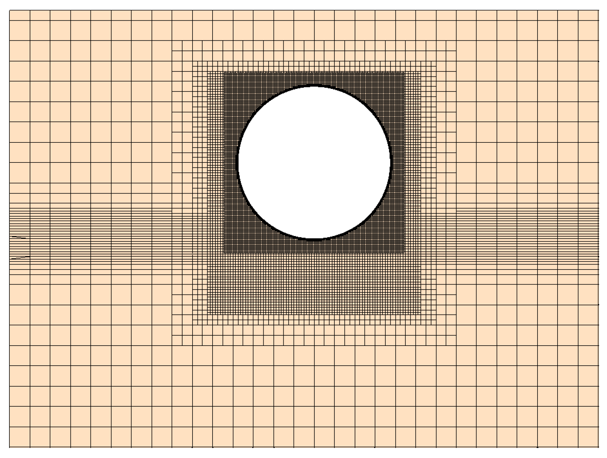
2.2. Fluid Domain and Boundary Conditions

Figure 1 shows the computational domain of the numerical model. The lowest point of the sphere lies in the static surface of the water at time t = 0 . V 0 represents the initial vertical velocity of the free-fall water entry. The dimensions of the domain can be determined by the lengths ba, bc, be, and eb’, which are 8R, 8R, 3R, and 3R, respectively. R is the radius of the sphere.
The surfaces abcd and a’b’c’d’ were set to velocity inlet. Only water is allowed to enter into the surface abcd, and only air is allowed to enter into the surface a’b’c’d’. The velocities of water and air in these surfaces were both zero. The surfaces abb’a’, add’a’, bcc’b’, and cdd’c’ were set to pressure outlet, and the pressure at the outlet is relative pressure P = ρ g h , in which ρ is the density of water, g is the gravity acceleration, and h is the depth of water. The surface of the sphere was set to no-slip wall. The overset mesh condition was applied to the interface between the background region and the overset region. The six freedoms of the sphere were activated by using the dynamic fluid body interaction (DFBI) method.
Figure 2 shows the computational mesh on a plane section. In order to simulate the interaction between the sphere and the water accurately, fine mesh was assigned to the region where the sphere may pass.

3. Discussion on the Numerical Model

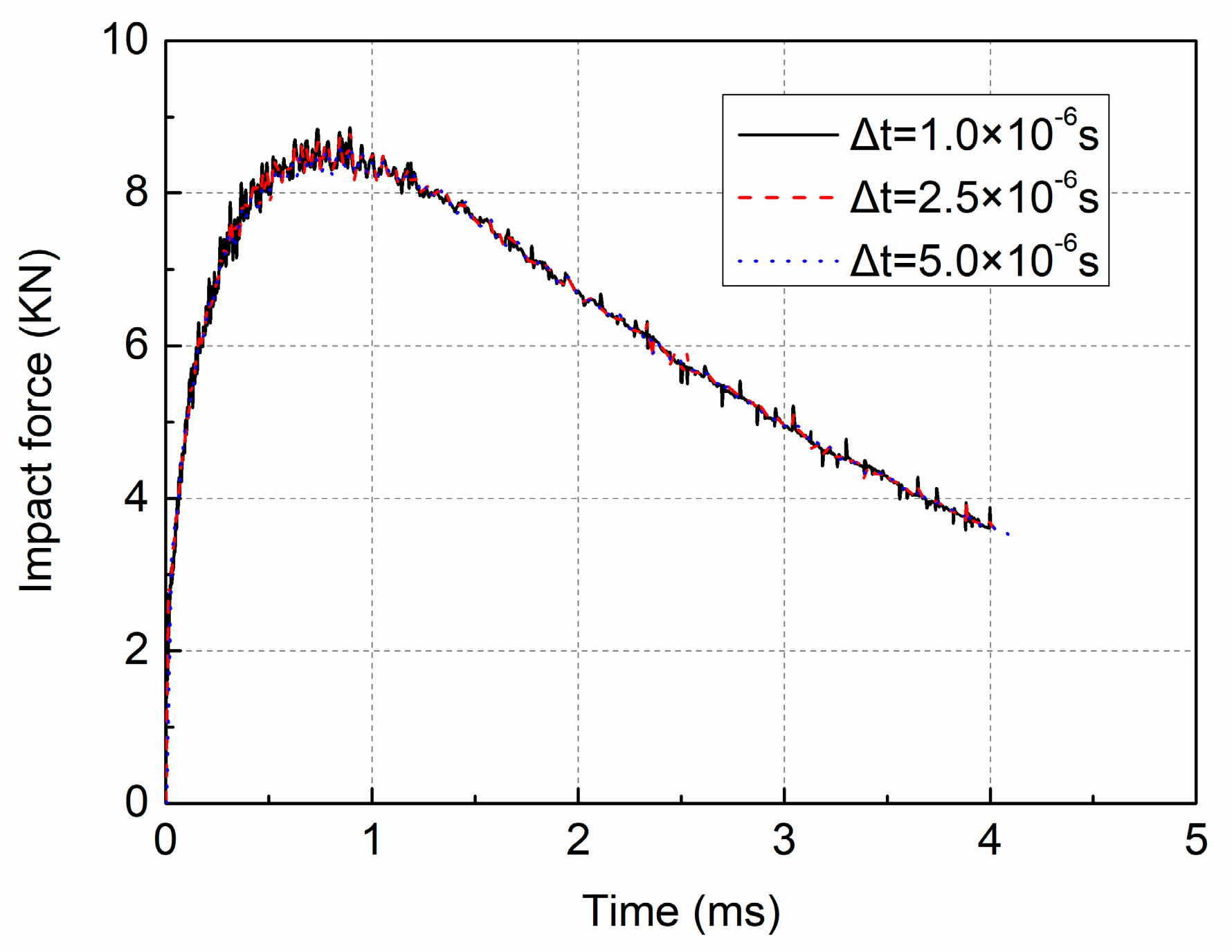
3.1. Convergence Study

Careful selection of mesh density and time-step is required for the CFD simulation in water-entry problems. Figure 3 shows the impact force with three different mesh densities during the free-fall water entry. F is the impact force of the total sphere, and its positive direction is vertically upward. The non-dimensional mass m* was introduced to describe the mass of the sphere, and it is defined as m* = 3 m/(4ϼπR3), where m is the mass of the sphere, R is the radius of the sphere and ϼ = 1000 kg/m3 is the density of water. R, m*, and V0 were set to 0.15 m, 1.0, 16 m/s in the mesh convergence study, respectively. The contact angle of the wetting sphere is 90°. The time-step was set to 2.5 × 10⁻⁶ s for different mesh densities. It can be seen that the impact forces with different mesh densities show good consistency, even though there were some numerical oscillations in the history of the impact force. The mesh configuration with medium density was considered to be appropriate for the prediction of impact force during water entry of the sphere.
Three time-steps, Δ t = 1 × 10⁻⁶, 2.5 × 10⁻⁶, and 5 × 10⁻⁶ s, were discussed in the time-step convergence study. The mesh configuration with medium density was chosen. V 0 was set to 16 m/s. The other parameters of the sphere were the same as those in the mesh convergence study. As shown in Figure 4, the results of different time-steps show good convergence.
As shown in Figure 5, the values of convective Courant number near the sphere are less than one during the water entry, which indicates that time-step 2.5 × 10⁻⁶ s is an appropriate choice for the impact velocity V 0 = 16 m / s . There is no doubt that a greater impact velocity requires a smaller time-step to capture the details of the flow field during water entry. For other impact velocities, the time-step was set to ensure that the value of V 0 Δ t was less than 4 × 10⁻⁵ m (2.5 × 10−6 s × 16 m/s).

3.2. The Effect of the Contact Angle

The surface tension force is considered in the simulation of the water entry by using the CSF approach. The effect of the solid wall on the surface tension force is usually described as the contact angle θ. Figure 6 shows the impact force with three different contact angles during the free-fall water entry. The time-step was set to 2.5 × 10⁻⁶ s. The mesh configuration with medium density was chosen. R, m*, and V0 were set to 0.15 m, 1.0, and 16 m/s, respectively. As shown in Figure 6, the impact force with different contact angles are in good agreement, which means the variation of the contact angle has little effect on the impact force during early water entry. Therefore, the contact angle was set to 90° in the following simulation.

3.3. Validation

The present model was validated by the comparison of non-dimensional impact force with previous experimental and numerical results, as shown in Figure 7. The non-dimensional impact force CS is defined as C s = 2 F / ρ π R 2 V 0 2 , where F is the total impact force and V0 is the initial velocity. V0 is replaced by V for the constant-velocity water entry. The non-dimensional penetration depth is defined as D* = D/R, where D is the instantaneous penetration of the sphere below the calm water. The mesh configuration with medium density was chosen. The time-step was set to 2.5 × 10⁻⁶ s. The impact velocity V was constant at 16 m/s. R was set to 0.15 m. The comparison showed that the vertical force simulated by the present model agrees reasonably well with the experimental data of Nisewanger [20] and Baldwin and Steves [21], and the numerical result by Xiao and Zhang [16]. Thus, our numerical model is capable of simulating hydrodynamic force acting on the sphere during water entry.

4. Discussion of the Design Parameters

In the design of a spherical device for air-drop deployment, the impact loads acting on the sphere can threaten the safety of the housing structure, and the acceleration of the sphere can affect the work of internal sensors. In this section, the effects of the design parameters—namely impact velocity, radius, and mass of the sphere—on the impact force and the acceleration of the sphere are studied. To better study the effect of each parameter, only one parameter was varied at a time, while the other parameters were kept constant.

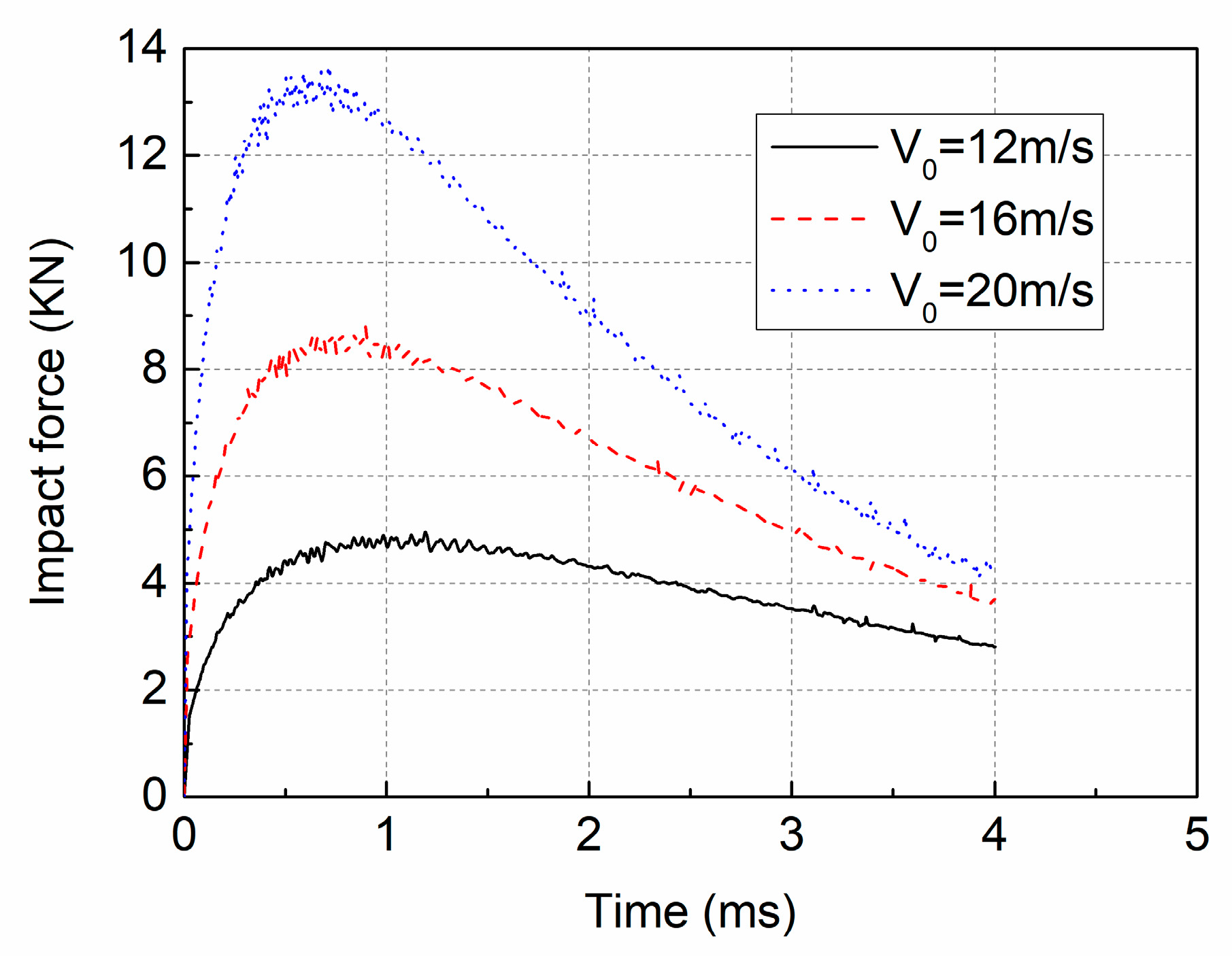
4.1. The Effect of the Impact Velocity

The initial impact velocity between the sphere and the water surface will change at different deployment heights. The vertical free-fall water entries with three different initial impact velocities were simulated. The time histories of the impact force and the acceleration of the sphere are shown in Figure 8 and Figure 9. The radius of the sphere, R , is 0.15 m. The non-dimensional mass of the sphere m * is equal to 1.0.
It can be seen that the peak values of the impact force and the acceleration increase with an increase in impact velocity. For a larger impact velocity, the impact force and the acceleration rise and fall faster. Figure 10 shows the relationship between the non-dimensional impact force and the non-dimensional penetration. The results of different impact velocities show very good consistency and the change of the non-dimensional impact force depends on the penetration of the sphere.
Figure 11 shows the pressure contours of different time instants. V 0 was set to 16 m/s. In the initial stage of the water entry, the maximum pressure was located near the spray root of the water surface. With the fall of the sphere, the pressure values drop quickly, and the maximum pressure moves towards the lower part of the bottom surface.

4.2. The Effect of the Radius

In the design process, the radius of the sphere will be increased when the required installation space of the equipment inside the device increases. The vertical free-fall water entries of the sphere with four different radii are simulated. The time histories of the impact force and the acceleration of the sphere are shown in Figure 12 and Figure 13. The initial velocity is 12 m/s. The non-dimensional mass of the sphere m * is equal to 1.0.
It can be seen that the peak value of the impact force increases with an increase in radius, while the peak value of the acceleration decreases with an increase in radius. Figure 14 shows that the history of the non-dimensional impact force is independent of the radius of the sphere. According to the definition of the non-dimensional impact force C s = 2 F / ρ π R 2 V 0 2 , the impact force is linearly proportional to the square of the radius of the sphere for the same non-dimensional penetration and initial velocity. Based on Newton’s second law, the acceleration of the sphere can be expressed as a = F / m g = 3 C s ρ V 0 2 / 8 R m * g , where g is the acceleration of gravity. It can be seen that the acceleration of the sphere is inversely proportional to the radius of the sphere, which leads to the sphere with larger radius experiencing a smaller acceleration, as shown in Figure 13.

4.3. The Effect of the Mass

In the design process, the mass of the sphere will be changed when the number of the equipment inside the device increases or decreases. The vertical free-fall water entries of the sphere with different masses were simulated. The radius of the sphere, R , is 0.15 m. The initial velocity is 12 m/s.
Figure 15 shows the time history of the impact force acting on the sphere with different masses. It can be seen that the impact force increases with an increase in mass. The difference of the impact force between m * = 0.8 and m * = 1.0 is obviously smaller than that between m * = 0.2 and m * = 0.4 , which shows that the influence of the variation of mass on the impact force becomes weaker with an increase in mass. For the same impact velocity, the sphere with smaller mass has smaller momentum, and the velocity of the sphere decreases faster, as shown in Figure 16. Hence, the impact interaction between the sphere and water is weakened with a decrease in mass.
Figure 17 shows that the acceleration of the sphere increases with the decrease in the mass. From the expression of the acceleration a ( t ) = F ( t ) / m g , it can be seen that the acceleration of the sphere is proportional to the impact force acting on the sphere, and inversely proportional to the mass of the sphere. Although the decrease in mass can reduce the impact force acting on the sphere, the comprehensive effect of the impact force and the mass can lead to an increase in the acceleration of the sphere. As shown in Figure 18, the influence of the mass on the non-dimensional impact force is the same as that on the impact force, which is consistent with the definition of the non-dimensional impact force C s = 2 F / ρ π R 2 V 0 2 .

4.4. Simplified Formulas for the Prediction of Peak Values

The peak values of the impact force and the acceleration correspond to the maximum requirement in the design of the device. Based on Newton’s second law, the expression of the acceleration a ( t ) = F ( t ) / m g . Then, it can be seen that the peak values of the impact force and the acceleration should appear at the same time for a certain sphere, and the acceleration can be calculated when the impact force is determined.
From the above discussion, it can be seen that the peak value of the non-dimensional impact force is independent of the impact velocity and the radius in the concerned design parameter range (0.15 m ≤ R ≤ 0.60 m and 12 m/s ≤ V0 ≤ 20 m/s), but is influenced by the mass of the sphere. The relationship between the peak value of C s and the non-dimensional mass is fitted with a polynomial, as shown in Figure 19 and the expression is
C s m = 2.3576 m * 5 7.749 m * 4 + 10.068 m * 3 6.6608 m * 2 + 2.4633 m * + 0.4629 ( 0.15   m     R     0.60   m , 12   m / s     V 0     20   m / s   and   0.2     m *     1.0 ) ,
where C s m is the peak value of C s .
Then, when the initial velocity, the radius, and the mass of the sphere are given in the design of the spherical measuring device for air-drop deployment, the peak values of the impact force and acceleration can be calculated in the following equations.
F m = ρ C s m π R 2 V 0 2 / 2
a m = F m / m g
where F m and a m are the peak values of the impact force and the acceleration, respectively.

5. Conclusions

The free-fall water entry of a sphere was numerically investigated by using the transient RANS method. Convergence study is carried out, which accounts for the mesh density and time-step independence, and the appropriate selection of the mesh density and the time-step for the water-entry simulation of the sphere is achieved. The present model is validated by the comparison of non-dimensional impact force with the experimental data by Nisewanger (1961) and Baldwin and Steves (1975), and the numerical result by Xiao and Zhang (2012). Then, the effects of parameters such as impact velocity, radius, and mass of the sphere on the impact force and the acceleration of the sphere were studied by using the validated model and the following conclusions were drawn:
(1)
The sphere with higher impact velocity experienced a larger impact force and larger impact acceleration.
(2)
The sphere with a larger radius experienced a larger impact force and smaller impact acceleration.
(3)
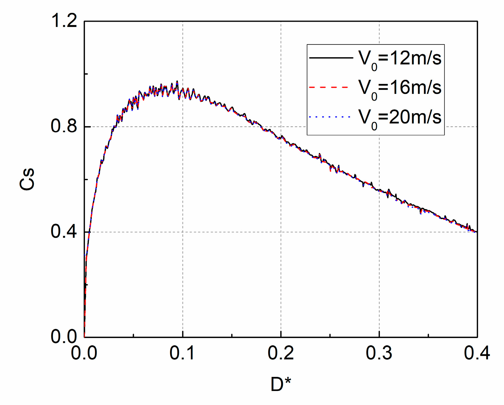
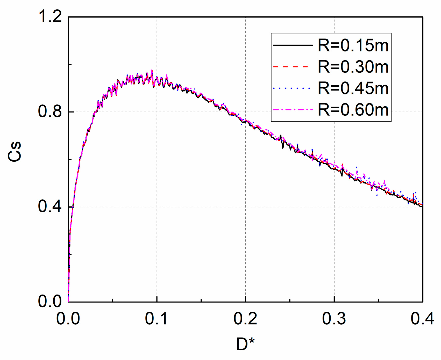
By selecting the impact velocity and the radius of the sphere to make the impact force non-dimensional, the contribution of the impact velocity and the radius to impact force was eliminated. It was found that the non-dimensional impact force is independent of the impact velocity and the radius of the sphere.
(4)
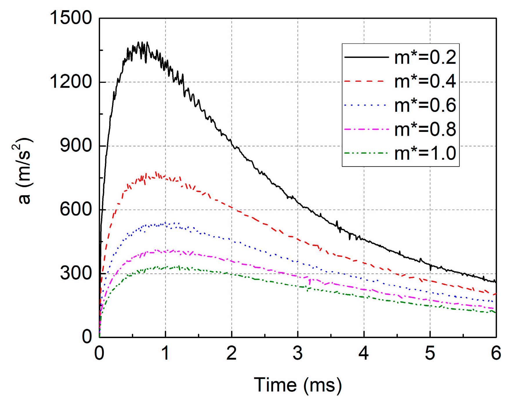
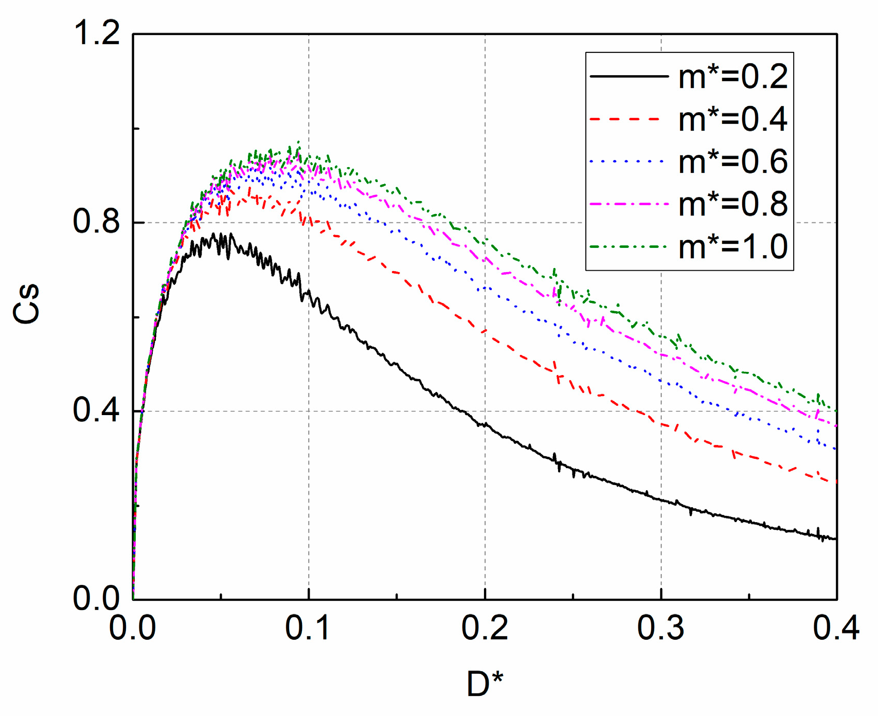
With an increase in the mass of the sphere, the impact force acting on the sphere decreased, but the acceleration of the sphere increased. The influence of the variation in mass on the impact force and the acceleration became weaker with an increase in mass.
(5)
Simplified formulas for the prediction of the peak values of the impact force and acceleration were achieved by fitting the relationship between the peak value of the non-dimensional impact force and the non-dimensional mass. These formulas will be useful in the design of the spherical measuring device for air-drop deployment.

Author Contributions

All authors contributed equally to forming the objectives of this paper and participated in discussion of the numerical simulations and results. P.Y. and C.S. performed the simulations, analyzed the data and wrote the paper under the supervision of T.W., C.Z. and H.T. revised the paper.

Funding

The authors are grateful to the National Science Foundation of China (Grant No. 51709030), the Fundamental Research Funds for the Central Universities (3132017032), the Doctoral Startup Foundation of Liaoning Province (20170520436) and the National Key Research and Development Program of China (No. 2016YFC0301500) for supporting this work.

Conflicts of Interest

The authors declare no conflict of interest.

References

  1. Von Karman, T. The Impact on Seaplane Floats during Landing. Tech. Rep. Arch. Image Librar. 1929. Available online: https://digital.library.unt.edu/ark:/67531/metadc54062/ (accessed on 15 March 2019).
  2. Wagner, H. Uber Stoss-und Gleitvorgange an der Oberflache von Flussigkeiten. ZAMM 1932, 12, 193–215. [Google Scholar] [CrossRef]
  3. Korobkin, A. Analytical models of water impact. Eur. J. Appl. Math. 2004, 15, 821–838. [Google Scholar] [CrossRef]
  4. Tassin, A.; Jacques, N.; Alaoui, A.; Nême, A.; Leblé, B. Assessment and comparison of several analytical models of water impact. Int. J. Multiphys. 2010, 4, 125–140. [Google Scholar] [CrossRef]
  5. Stenius, I.; Rosén, A.; Kuttenkeuler, J. Explicit FE-modelling of fluid–structure interaction in hull–water impacts. Int. Shipbuild. Prog. 2006, 53, 103–121. [Google Scholar]
  6. Stenius, I.; Rosén, A.; Kuttenkeuler, J. Explicit FE-modelling of hydroelasticity in panel-water impacts. Int. Shipbuild. Prog. 2007, 54, 111–127. [Google Scholar]
  7. Wang, S.; Soares, C.G. Slam induced loads on bow-flared sections with various roll angles. Ocean. Eng. 2013, 67, 45–57. [Google Scholar] [CrossRef]
  8. Yu, P.; Li, H.; Ong, M.C. Numerical study on the water entry of curved wedges. Ships Offshore Struct. 2018, 13, 885–898. [Google Scholar] [CrossRef]
  9. Wang, S.; Soares, C.G. Numerical study on the water impact of 3D bodies by an explicit finite element method. Ocean. Eng. 2014, 78, 73–88. [Google Scholar] [CrossRef]
  10. Bilandi, R.N.; Jamei, S.; Roshan, F.; Azizi, M. Numerical simulation of vertical water impact of asymmetric wedges by using a finite volume method combined with a volume-of-fluid technique. Ocean. Eng. 2018, 160, 119–131. [Google Scholar] [CrossRef]
  11. Cheng, Y.; Ji, C.; Zhai, G. Numerical investigation of water entry of a wedge into waves with current effects using a fully nonlinear HOBEM. Ocean. Eng. 2018, 153, 33–52. [Google Scholar] [CrossRef]
  12. Mirzaii, I.; Passandideh-Fard, M. Modeling free surface flows in presence of an arbitrary moving object. Int. J. Multiphas. Flow. 2012, 39, 216–226. [Google Scholar] [CrossRef]
  13. Iranmanesh, A.; Passandideh-Fard, M. A three-dimensional numerical approach on water entry of a horizontal circular cylinder using the volume of fluid technique. Ocean. Eng. 2017, 130, 557–566. [Google Scholar] [CrossRef]
  14. Ahmadzadeh, M.; Saranjam, B.; Fard, A.H.; Binesh, A.R. Numerical simulation of sphere water entry problem using Eulerian–Lagrangian method. Appl. Math. Model. 2014, 38, 1673–1684. [Google Scholar] [CrossRef]
  15. Abraham, J.; Gorman, J.; Reseghetti, F.; Sparrow, E.; Stark, J.; Shepard, T. Modeling and numerical simulation of the forces acting on a sphere during early-water entry. Ocean. Eng. 2014, 76, 1–9. [Google Scholar] [CrossRef]
  16. Xiao, H.; Zhang, X. Numerical investigation of the fall rate of a sea-monitoring probe. Ocean. Eng. 2012, 56, 20–27. [Google Scholar] [CrossRef]
  17. Akers, B.; Belmonte, A. Impact dynamics of a solid sphere falling into a viscoelastic micellar fluid. J. Non-Newton. Fluid Mech. 2006, 135, 97–108. [Google Scholar] [CrossRef]
  18. Do-Quang, M.; Amberg, G. Numerical simulation of the coupling problems of a solid sphere impacting on a liquid free surface. Math. Comput. Simul. 2010, 80, 1664–1673. [Google Scholar] [CrossRef]
  19. Menter, F.R. Two-equation eddy-viscosity turbulence models for engineering applications. AIAA J. 1994, 32, 1598–1605. [Google Scholar] [CrossRef] [Green Version]
  20. Nisewanger, C. Experimental Determination of Pressure Distribution on a Sphere During Water Entry; Naval Ordnance Test Station: China Lake, CA, USA, 1961. [Google Scholar]
  21. Baldwin, L.; Steves, H.X. Vertical Water Entry of Spheres; White Oax Laboratory: Silver Spring, MD, USA, 1975; p. 76. [Google Scholar]
Figure 1. Computational domain.
Jmse 07 00122 g001
Figure 2. Computational mesh on a plane section.
Jmse 07 00122 g002
Figure 3. The impact force with different mesh densities during the free-fall water entry of the sphere.
Jmse 07 00122 g003
Figure 4. The impact force with different time-steps during the free-fall water entry of the sphere.
Jmse 07 00122 g004
Figure 5. Values of convective Courant number with different time instants.
Jmse 07 00122 g005
Figure 6. The impact force with different contact angles during the free-fall water entry of the sphere.
Jmse 07 00122 g006
Figure 7. The comparison of non-dimensional impact force between the present method and the previous experimental and numerical results.
Jmse 07 00122 g007
Figure 8. The time history of the impact force with different impact velocities.
Jmse 07 00122 g008
Figure 9. The time history of the acceleration with different impact velocities.
Jmse 07 00122 g009
Figure 10. Variations of the non-dimensional impact force with different impact velocities.
Jmse 07 00122 g010
Figure 11. Pressure contours with different time instants.
Jmse 07 00122 g011
Figure 12. The time history of the impact force with different radii.
Jmse 07 00122 g012
Figure 13. The time history of the acceleration with different radii.
Jmse 07 00122 g013
Figure 14. Variations of the non-dimensional impact force with different radii.
Jmse 07 00122 g014
Figure 15. The time history of the impact force acting on the sphere with different masses.
Jmse 07 00122 g015
Figure 16. The velocity of the sphere with different masses during the free-fall water entry.
Jmse 07 00122 g016
Figure 17. The time history of the acceleration with different masses.
Jmse 07 00122 g017
Figure 18. Variations of the non-dimensional impact force with different masses.
Jmse 07 00122 g018
Figure 19. The relationship between the peak value of and the non-dimensional mass.
Jmse 07 00122 g019

