Article

A Fast Simulation Method for Damaged Ship Dynamics

Department of Industrial Engineering, University of Naples “Federico II”, Via Claudio 21, 80125 Napoli, Italy
*
Author to whom correspondence should be addressed.
J. Mar. Sci. Eng. 2019, 7(4), 111; https://doi.org/10.3390/jmse7040111
Submission received: 27 March 2019 / Revised: 9 April 2019 / Accepted: 16 April 2019 / Published: 19 April 2019
(This article belongs to the Special Issue Advances in Marine Dynamic Simulation)

Abstract

:
Ship accidents that entail flooding may lead to disastrous consequences which could be avoided or mitigated based on the knowledge of damaged ship dynamics. The dynamic behaviour of a damaged hull is a complex phenomenon involving the interaction of the flooded water and the ship motions. The presence of a damage opening allows water flow into and out from the compartment, which further complicates the mathematical description of the problem. A fast simulation method, based on the lumped mass approach, is developed and presented. The lumped mass path in space depends on free-surface inclinations that differ from the ship angles of the roll and pitch. The viscous effects in the floodwater dynamics are implemented based on the model for the dissipation of the energy of standing waves in rectangular rooms. The method applies to both the transient stage of flooding and to the dynamic behaviour of a flooded ship in regular waves. In the first case, viscous effects are implemented considering the water in the compartment variable with time. Several case studies are carried out on three different hull models: Transient stage of flooding, roll decay of the damaged hull, and steady state responses in waves are simulated and compared with available experimental data.

1. Introduction

The improvement in the safety of a damaged ship is oriented towards simulation-based guidelines on critical scenarios [1,2]. Following this trend, the possibility to provide a fast simulation tool, estimating the damaged ship dynamics, represents a valuable challenge. Numerical simulations can approach the complex problem of the ship motions and floodwater coupling more efficiently and economically than model tests.
Several calculation methods have been developed, concerning the ship damage stability in the time domain. Among these, the most accurate are computational fluid dynamics (CFD) approaches, such as the mesh-less technique named smoothed-particle hydrodynamic (SPH) [3,4] and volume of fluid methods (VOF) [5,6,7]. In general, CFD is used intensively for studying sloshing phenomena [8,9,10] and many efforts are made to couple them with the dynamics of a damaged ship in waves [7,11,12].
Notwithstanding that these methods prove to yield accurate results, their computation time is still a limit for wider applications.
By using fast methods based on potential flow with different levels of simplifications in boundary conditions, an acceptable accuracy of flow motion can be obtained [13]. Developing fast numerical simulation tools, capable of modelling water dynamics inside a compartment, is a state of the art challenge. Some of them are based on the lumped mass approach [14]; some of them are based on shallow water equations [15,16]. In [17,18], the so-called quasi-static approach was introduced as the coupling of the equations of motions of a flooded ship in waves with the floodwater, characterized by a flat free surface, moving in phase with the ship. The quasi-static approach fails significantly in predicting the roll behaviour and the resonant condition of ships with partially flooded compartments [17,19].
In [20,21], a novel method in simulating water flooding and its effects on ship motions was presented. It is based on the lumped mass approach, considering the inclination of a flat free-surface due to the action of the ship’s lateral acceleration and thus the more accurate position of the lumped mass.
The current paper presents improvements of the method developed in [20,21], accounting for the water exchange through the damage opening in ship dynamics and accounting for longitudinal acceleration effects in the free-surface inclination.
The presented method is intended to be an intermediate approach between the quasi-static methods (uncoupled) and fully coupled simulations for ship motions with flooded compartments in waves. The coupling is realized by accounting for the pressure distribution of the liquid induced by the acceleration of the lumped mass. The description of the numerical model is provided in the following sections.
The method applies both to the transient stage and to the steady-state stage of flooding [22]. Therefore, case studies are carried out for three hulls involving different damage simulations: A barge dealing with transient flooding [23]; a damaged ferry in a steady state that exhibits two frequency modes [24]; and a damaged frigate dealing with steady state dynamics in head and beam waves [25]. The comparison with the available experimental data [23,24,25] highlights the pros and cons of the fast model, according to the simulated damage cases and comments on the obtained accuracy.

2. Numerical Model

The equations of motion in the time domain for a damaged ship, for six degrees of freedom (6 DoF), are extensively described in [21]. In this section, the main assumptions of the model and the current improvements are given.
In modelling ship dynamics, the hull is assumed as a rigid body with zero speed. A discrete representation of the hull, using triangular panels, is adopted:
m [ u ˙ + ω × u ] = f e x t + m g f i
I ω ˙ + ω × I ω = m e x t r i × f i
m i [ u ˙ + ω ˙ × r i + ω × ( u + ω × r i ) + u ˙ i + 2 ω × u i ] + + m i ˙ ( u + u i + ω × r i ) = f i + m i g
The external forces and moments, namely fext and mext, consist of restoring, radiation, and wave actions that are Froude-Krylov forces and moments and diffraction [26]. The so-call blended approach is adopted: It consists in linear diffraction and radiation forces (based on potential theory [27]) and includes all pertinent non-linearities in Froude-Krylov and hydrostatic forces.
As is well known, the damping in the potential theories is due to the wave radiation away from the body and it is not accurate enough for the roll motion. The other contribution in damping can be introduced in the numerical model or as Ikeda’s correction or from the experimental assessment of linear (α), quadratic (β), and cubic (γ) extinction coefficients as defined in [28].
The damage is simulated by the added weight technique. The flooded water, mi, is modelled as a lumped mass (3), whose position and velocity are ri and ui, respectively.
The position of the lumped mass, ri, is restrained on a discrete three-dimensional path, depending on the amount of flooded water and on the free surface inclination in the longitudinal and lateral direction. The free surface of the floodwater is treated as a flat surface. It can have different inclinations from the ship roll and pitch angles. The inclinations of the free surface are evaluated by the analogy with the pressure distribution in a liquid within a tank that is uniformly accelerated [29]. It holds:
p = ρ ( g a L )
where a L is the acceleration of the lumped mass in body fixed coordinates (aL = aLx i + aLy j + aLz k). It is equal to:
a L = [ u ˙ + ω ˙ × r i + ω × ( u + ω × r i ) + u ˙ i + 2 ω × u i ]
Therefore, the acceleration in the inertial system reference is obtained (aLi = aLix I + aLiy J + aLiz K). The effect of the transversal acceleration component, aLiy, is appreciated in roll motion, while the longitudinal acceleration component, aLix, will contribute in pitch motion, yielding to the so called “effective”ge as follows:
g e = g K ( a L i x I + a L i y J )
If the ship has instantaneous roll and pitch angles (ϕ and θ) and the lumped mass has accelerations, a L i x and a L i y , the free surface, in the body fixed frame, will be inclined of angles, ϕe (see for example Figure 1) and θe:
ϕ e = ϕ t a n 1 ( a L i y g )
θ e = θ t a n 1 ( a L i x g )
Viscous effects in the floodwater dynamics are applied only to roll inclinations, ϕ e , according to [14,30]. The transversal acceleration component, a L i y , in Equations (6a) and (6b) is replaced by a L i y δ f ϕ e ˙ | r i y | . The friction coefficient, δ f , is obtained from a reference model based on the dissipation of the energy of standing waves in rectangular rooms [14,30]:
δ f = k g π ω 2 c o s h ( k h ) 2   μ 2 ρ ω { s i n h ( 2 k h ) + k l [ s i n h ( 2 k h ) 2 k h ] + k l }
For the simulation of the transient stage of flooding, the water height is assumed as being variable with time, h(t), thus the friction coefficient is time dependent.

3. Flooding Law Modelling

Some of the damage scenarios that are studied and simulated in the applications present a damage opening on the side. Damaged ship roll is affected by flooding water exchange. This is implemented in the numerical simulation by means of the flooding law (9,10), where Q is the flow rate:
m i ( t ) = 0 t ρ Q ( t ) d t
Q ( t ) = s i g n ( H o H t ) 2 3 l 0 C D H 0 ( t ) 2 g | H ( t ) |
where H(t) = H0 (t)Ht(t);
The sea water height, H0, and the flooded water height, Ht, vary in time, according to the ship dynamics (see Figure 2).
In case of H(t) < 0, a routine that models water spilling from the compartment is implemented. In other words, when the sign of the flow rate is positive, the compartment is filled by floodwater; conversely, when the sign becomes negative, floodwater is removed from the compartment.
In all flooding applications, the discharge coefficient, CD, is 0.65, in analogy with [14]. Additional details for Section 2 and Section 3 can be found in [20,21].
Longitudinal acceleration effects, θe, the friction coefficient variable with time, δ f ( t ) , together with the flooding law modelling, are the novel enhancements to the model presented in the previous research [21].

4. Case Studies

The accuracy of the numerical model was exanimated for three different hull models: A barge, a passenger ferry, and a frigate, DTMB 5415 (see main data in Table 1, Table 2 and Table 3, respectively), in different flooding conditions. For these hulls, experimental data and model geometry are available [23,24,25].
Simulation time depends mainly on the panel discretization of the ship and on the time step. In the previous research [21], it was highlighted that the computational time is almost three times faster than real time (hull discretized by 56,456 panels and a time step of 0.25 s).

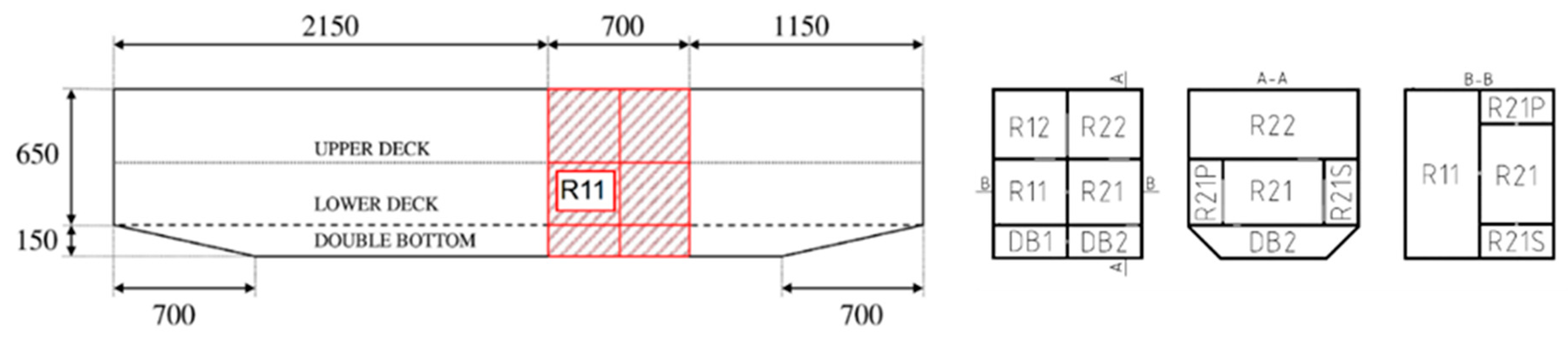
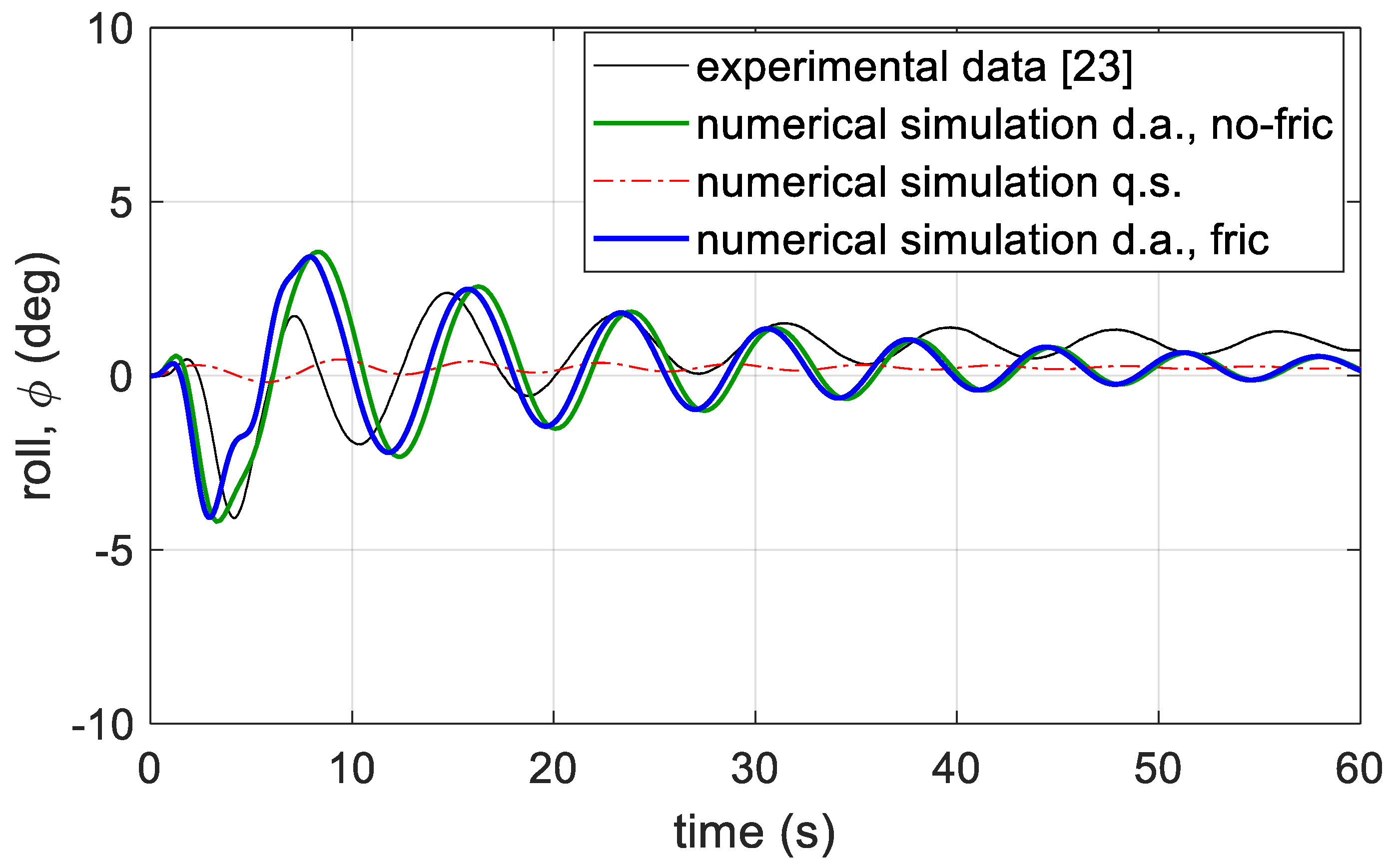
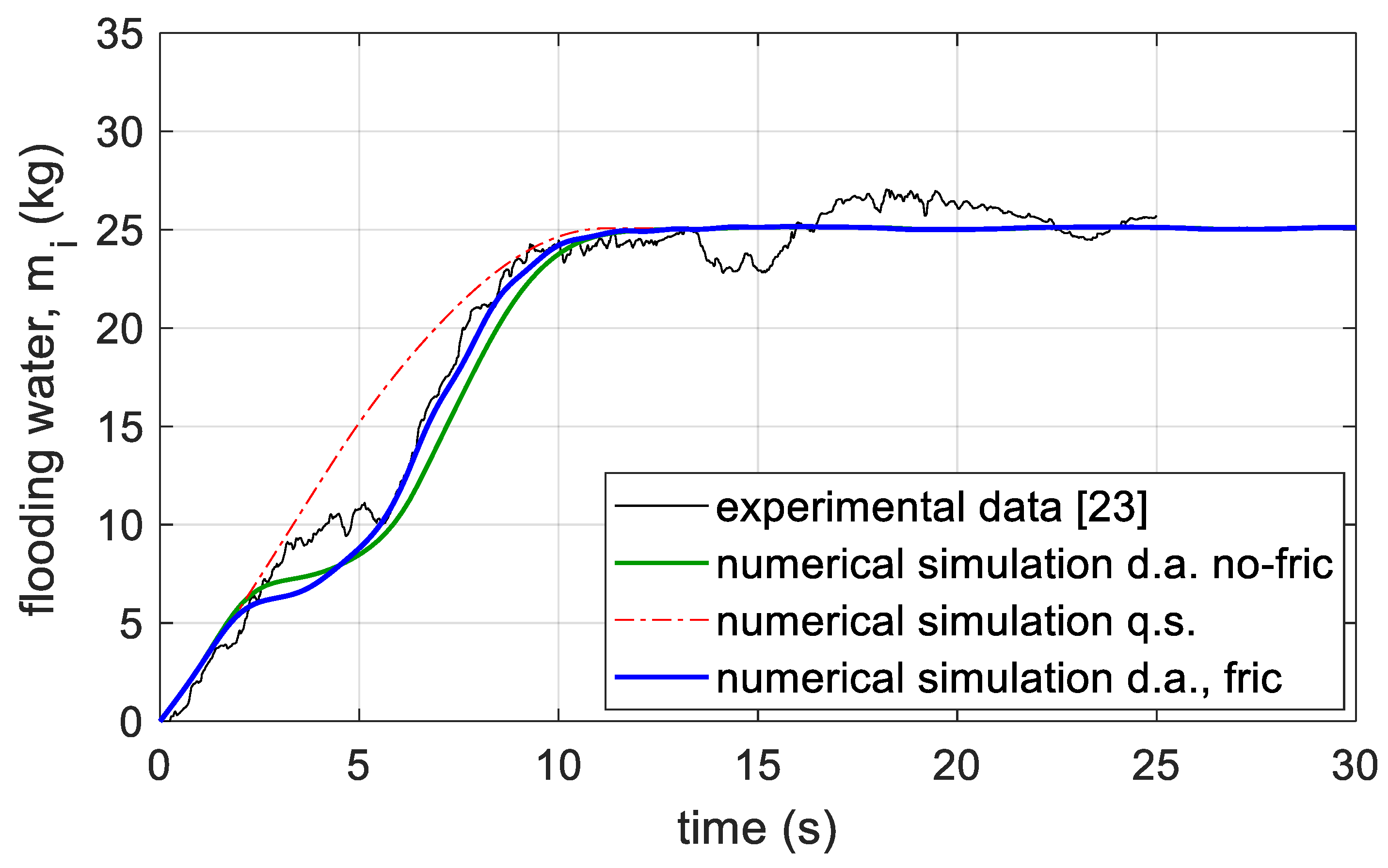
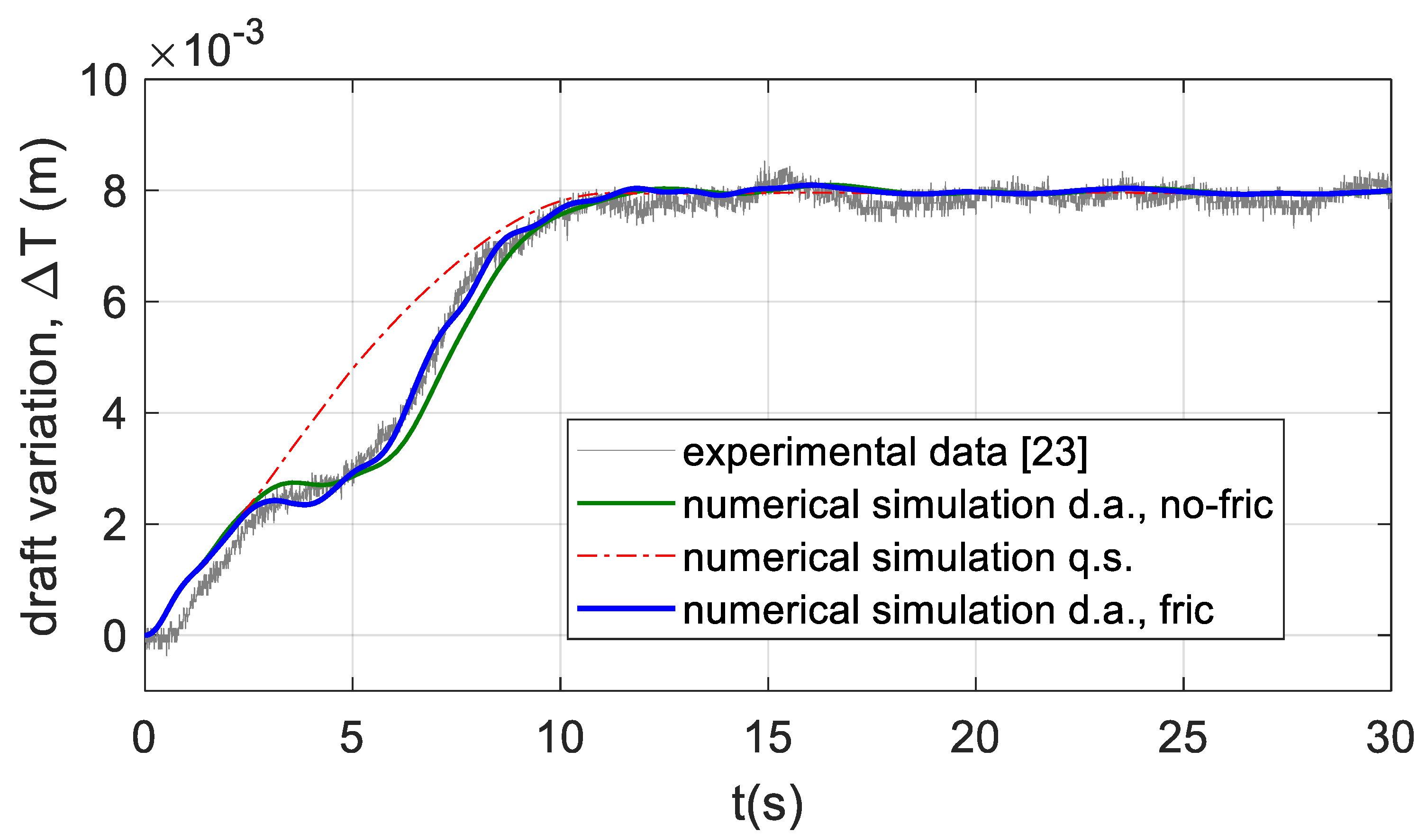
4.1. Flooding Simulations on the Barge Model

The first application carried out is the transient flooding of the compartment, R11, shown in Figure 3, of the barge model in still water. Principal barge and side opening characteristics are reported in Table 1. The still water condition allows observations of the effects of water dynamics on the ship roll response to be made, wave forces are equal to zero and added mass and damping matrices are taken from the reference work [14]; non-linear damping effects are neglected. The simulations are carried out in the model scale at zero speed.
In this scenario, the longitudinal inclination of the free surface does not influence the ship dynamic response that is mainly governed by lateral motions. Therefore, the lateral inclination of the free surface, ϕe, is calculated from Equation (7) while the longitudinal inclination equals the pitch angle of the barge, θ. The dissipation of the energy of standing waves in rectangular rooms, expressed by Equation (8), is herein implemented accounting for the variable height of water in the compartment, h = h(t). This allows for modelling of the friction effects during the transient stage of flooding to be conducted.
The numerical simulation results are obtained by: The dynamic modelling of the flat free surface without friction effects (d.a., no-fric), the dynamic modelling of the flat free surface with internal friction effects (d.a., fric), and the quasi-static modelling of the flat free surface (q.s.).
In Figure 4, Figure 5 and Figure 6, the numerical results are shown and compared with available experimental data.
The measured roll angle (see Figure 4—black line) presents two peaks, one smaller one larger, within the first 10 s of the time history. The dynamic modelling of the free surface (see d.a., fric and d.a., no-fric in Figure 4) provides accurate results regarding the transient roll motions during flooding; the two initial peaks and the final roll angle are fairly identified by the simulations. The introduction of the friction model on the dynamic free-surface slightly increases the roll frequency of the transient stage, improving the obtained results compared to the experimental data.
Figure 5 and Figure 6 show the flooding water amount within the compartment and the change in draft, respectively. It is possible to observe that the transient stage lasts around 10 s; then, the water amount and the draft remain constant. The dynamic modelling of the free surface with friction effects (d.a., fric) shows good agreement with the experimental data with an overall improvement compared to the dynamic modelling with no friction (d.a., no-fric).
Moreover, once the transient stage ends, the system only dampens the excited roll motion (resembling a roll decay); this could explain the overlapping of the d.a., fric and d.a., no-fric roll outcomes once the transient stage effects are extinguished (see Figure 4).
Although the numerical results based on the developed dynamic approach do not exactly match the whole time history, they yield fair outcomes for a fast simulation method. It is worth noting that the differences between the d.a., fric, d.a., and no-fric outcomes are appreciable within the first 10 s (transient stage duration), then they converge to the same final equilibrium condition.
The quasi-static approach fails in modelling transient stages of flooding (Figure 4), in modelling the transient roll behaviour, (see Figure 5) and the consequent decay after roll excitation (Figure 6).

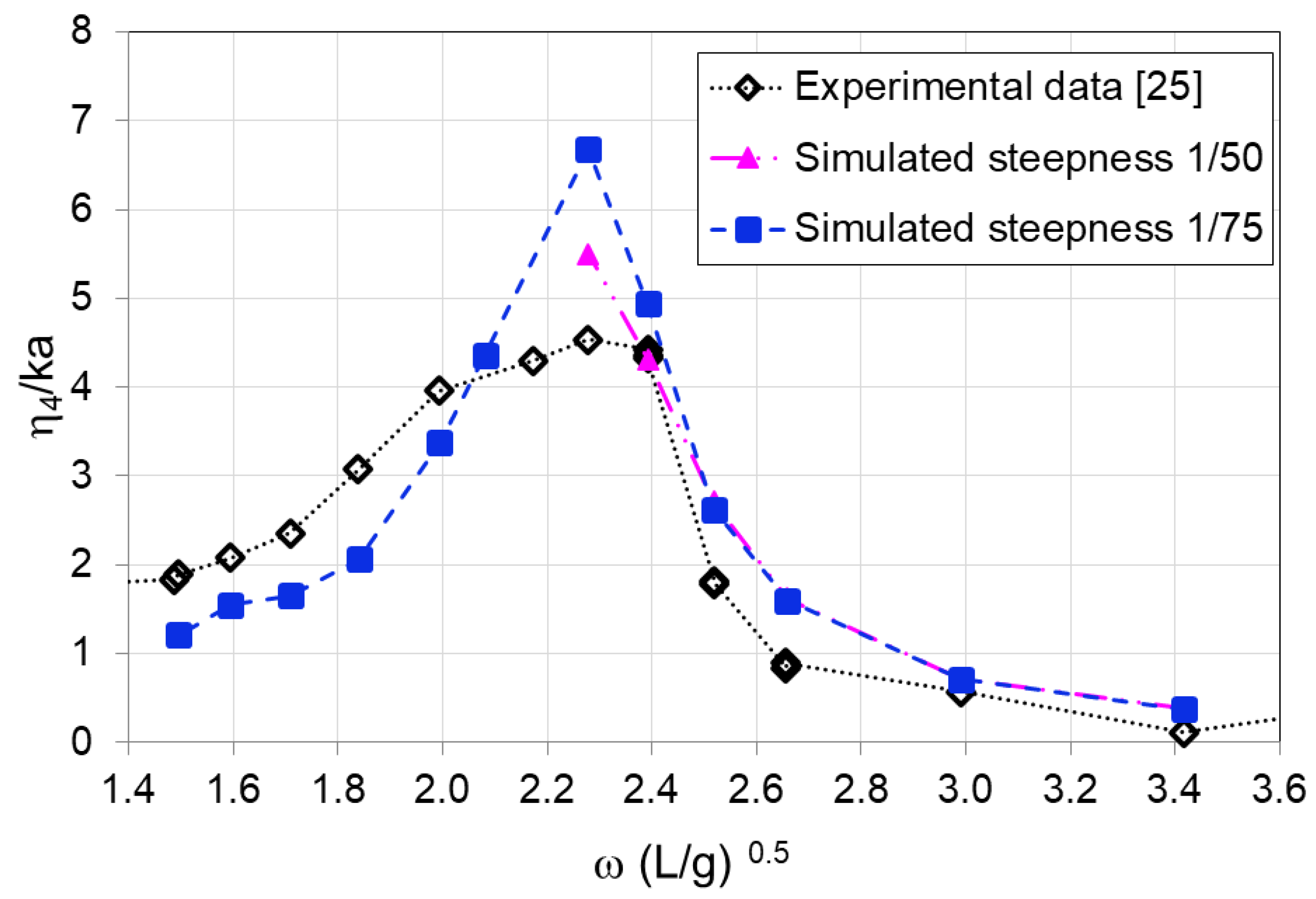
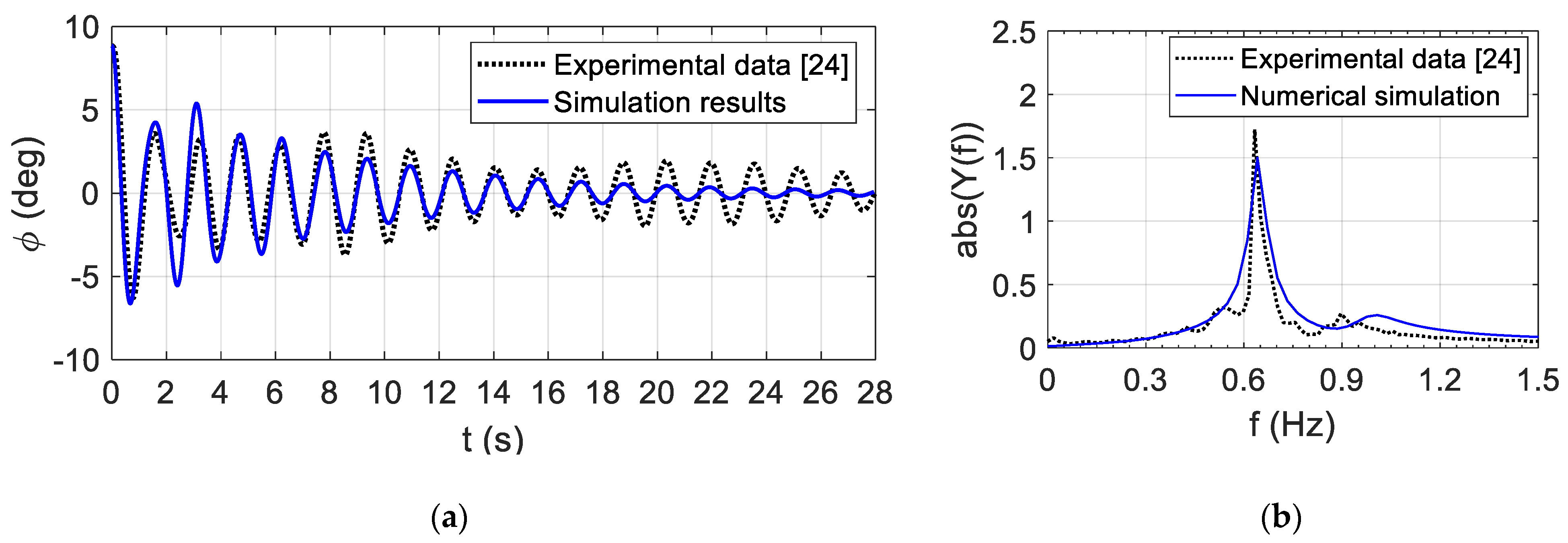
4.2. Roll Decay Simulations and Roll Response in Beam Waves on the Ferry Model

The passenger ferry model is used for simulating the free roll decay and roll behaviour in beam waves with a flooded compartment, in the absence of damage openings (see Figure 7). This case study focuses on the simulation of the steady state response of a flooded hull with a constant amount of water in time. The flooded tank is a whole compartment (see Figure 7), and it shows a filling ratio typical of an intermediate liquid depth [31]. It was observed experimentally that the roll response of this damaged hull is characterized by two frequency modes.
Once the numerical model is validated for the intact ship behaviour (both in still water and in regular beam waves), the ship compartment is flooded and simulations are carried out in the ship scale at zero speed. The ship-model scale factor, λ, is equal to 22. The numerical model accounts for the dynamic approach in modelling the free surface and for internal friction effects. The implemented friction model, developed for a rectangular tank, is less effective when applied to the considered flooded compartment, characterized by a prismatic geometry.
In Figure 8, the numerical roll decay test of the flooded ship reported in the model scale is compared against the corresponding experimental data. The numerical simulation (blue continuous line) matches the roll period of the flooded ship [24] and the rapid decay of the first two cycles. However, it does not feature a re-amplification of the roll motion as observable from the experimental data (black dotted line). The fast Fourier transform (FFT) analysis of the experimental data shows that the roll decay signal features two frequency modes. The numerical simulation fairly matches the first mode with 1% of difference: The simulated period is 1.560 s while the corresponding experimental period is 1.579 s. The second mode shows an error of 12% with a simulated period of 0.992 s simulated against 1.115 s of the experimental period.
The comparison of the damage ship roll response in the non-dimensional form, η4/ka, in beam waves is presented in Figure 9. The wave frequency is made non-dimensional dividing by L / g . The experimental data (diamond marker) show a two-peak behaviour usually observed in an anti-roll tank [32]. The numerical simulation (round marker) matches the general trend of the roll response curve in particular around 0.633 Hz (in the non-dimensional form, it is 2.38), i.e., the lower frequency peak. Moreover, looking at the phase diagram, in analogy with anti-roll tanks, the numerical simulation succeeds in modelling the maximum damping effects of the flooded tank at the non-dimensional frequency of 2.64, with a phase between the roll motion, ϕ, and free surface inclination, ϕe, of –90.6°. Although the implemented dynamic approach on the free surface fails in modelling the second peak of the roll response amplitude operator (RAO), it features both the two frequency modes, as observed from the roll decay simulations. Therefore, by the FFT analysis of the simulated roll decay, it is still possible to predict, with a certain accuracy, the exciting frequencies where roll motion amplifies.
The assumption of a flat free surface restrains the floodwater dynamics to feature only the first natural mode of sloshing. Indeed, this could explain the failure in predicting the second peak of the roll RAO. The deformable free surface of the floodwater might trigger resonance phenomena related to other natural modes of sloshing, responsible for the high frequency peak (see Figure 9).

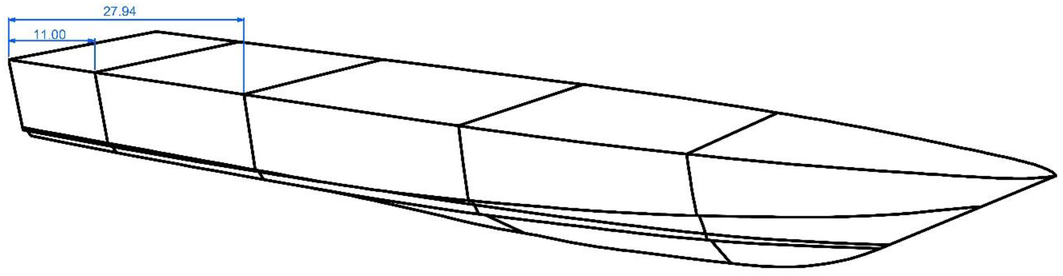
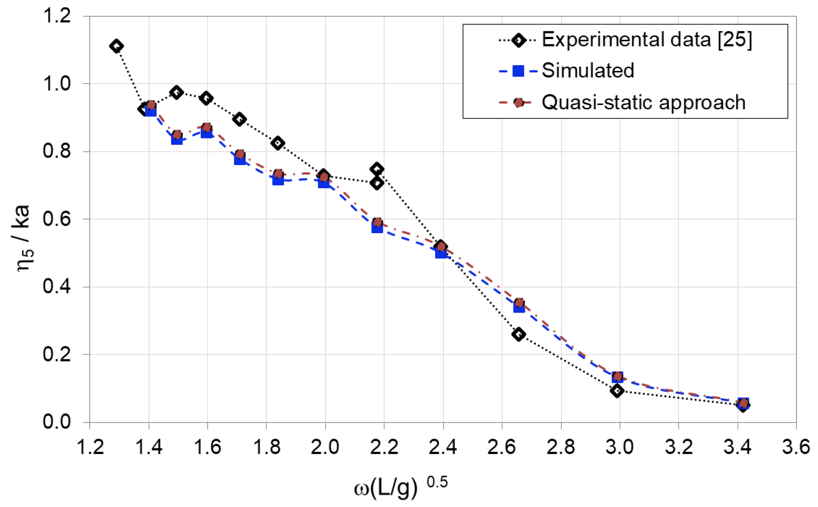
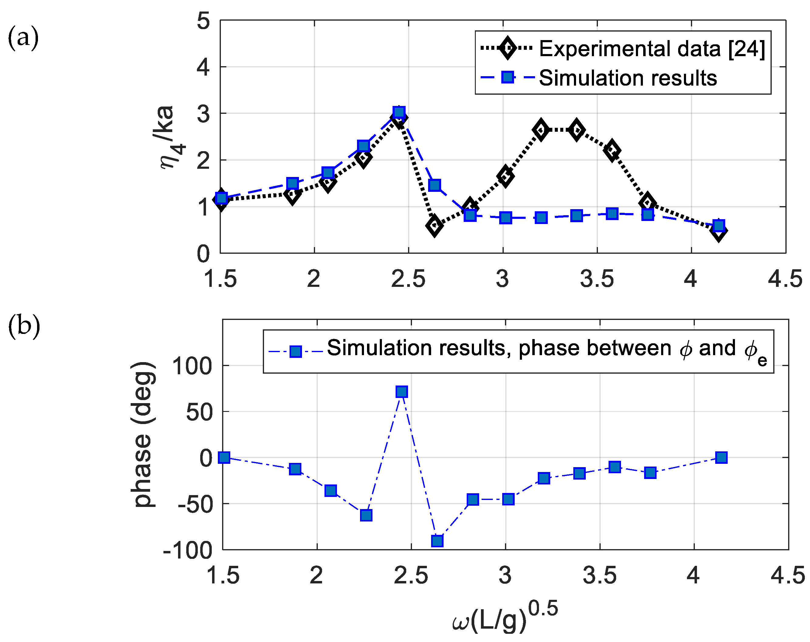
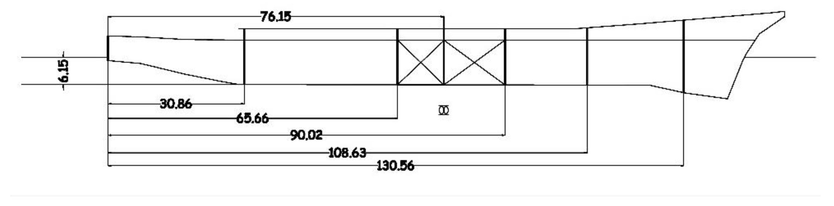
4.3. Motion Responses in Beam and Head Waves on the DTMB5415 Model

The third test case is the frigate model DTMB 5415 model (see Figure 10) for which several experiments concerning roll behaviour were carried out in damage conditions [25,33,34]. The ship’s main characteristics are listed in Table 3.
The numerical model is fully applied accounting for:
  • Non-linear damping.
  • Internal viscous effects.
  • Longitudinal dynamic effects on the free surface.
  • Water exchange through the opening.
  • Wave actions.
The quadratic damping coefficient, β, for the damaged hull is available from [35].
The first part of the applications regard the roll behaviour of the damaged hull in beam waves, while the second part focuses on head sea behaviour.
All the applications are carried out in ship scale at zero speed. The ship-model scale factor, λ, is equal to 51.
The wave steepness chosen for the simulations is H/λw = 1/80 to avoid wave heights that exceed the hull freeboard. This is a limit of the applicability of the implemented code also in the intact condition [21].
In Figure 11, the simulated results are compared with the available experimental data that correspond to a wave steepness of H/λw = 1/50. The roll response amplitude, η4, is obtained from FFT analysis of the simulated roll, referring to the first harmonic (the same applies also for the heave and pitch responses, η3 and η5, in Figure 12 and Figure 13, respectively). It is possible to notice that the simulated results are fairly close to the experimental ones except for the peak value at resonance. It is important to recall that the choice of a smaller wave steepness makes the non-linear damping actions less effective. Therefore, additional simulations are carried out for the wave steepness, H/λw = 1/50 (same as the experimental data), limited to the wave frequencies up to the peak value. In Figure 11, it can be observed that the simulated data with the larger steepness shows values closer to the experimental ones [25], although in a limited frequency range. Nevertheless, the numerical model is not fully effective in depicting the whole damping contribution of the damaged compartment. It is worth pointing out that in the simulations, the modelling of the water exchange through the opening affects the inertia and the restoring actions on the ship, rather than the water dynamics. Thus, the hydrodynamic problem through the damage opening, affecting the dynamics of the damaged hull, is only partially modelled.
However, the implemented fast model, based on an approximate approach, can simulate complex roll phenomena with a fair accuracy.
In Figure 12 and Figure 13, respectively, the pitch and heave RAO are shown for the same damaged hull in head sea. The simulation results are compared with the available experimental data. Simulations are repeated by means of the quasi-static approach on the free surface (i.e., same inclination as the ship). From the obtained outcomes, it seems that ship motions in the longitudinal plane (heave and pitch) are less sensitive to free surface dynamics. In this peculiar damage scenario, there is a poor sensitivity of the ship dynamics due to the longitudinal position of the flooded water. Therefore, both the quasi-static and dynamic approach on the free surface can fairly simulate the heave and pitch motions of a damaged ship in head sea. However, from the experimental campaign in head sea, excitation of the roll in all frequency ranges was observed due to fluid motions inside compartments. The comparison of the measured roll response in head sea with the simulated one exhibits that the numerical excitation of roll motions is far from the measured ones (see Figure 14). Concerning the experimental test [25], the authors underlined that due to the side opening, the flooded water could slosh and communicate without flow just with one side of the hull. The current modelling of the water exchange through the opening is not effective in properly simulating the above phenomenon. Nevertheless, the dynamic approach on the free surface inclination identifies an excitation of the roll motion, although smaller, while the quasi-static approach does not identify any (see Figure 14).

5. Conclusions

The results of three case studies on the flooded ship behaviour, obtained by the proposed fast simulation method, were presented. The ship motions were obtained from the so-call blended approach that combines linear diffraction and radiation forces (based on potential theory) and non-linear Froude-Krylov and hydrostatic forces.
Flooded water is considered as the lumped mass and its coupling with ship dynamics is realized by means of the accelerations of the inertial system. The present work discussed the accuracy of the introduced viscous effects of flooding water, and the implementation of the inertial effects instead of the quasi-static approach. All obtained results showed better agreement with the experimental ones with respect to the quasi-static approach, especially regarding roll motions.
Generally, the non-linear effects, which were observed during experiments, were obtained also by the simulations within reasonable differences.
Only the case study of the damaged ship’s heave and pitch motions in head sea was less sensitive to couplings between the ship and flooded water dynamics.
With this “extensive” validation of the method, it can be concluded that the proposed improvements can be easily implemented, gaining more correct insight of a damaged ship’s flooded water dynamics. Further enhancements in the numerical model are envisaged accounting for a non-flat free surface of the floodwater. Moreover, the flooding law in waves could be upgraded, including dynamic pressure effects, and a dynamic model for the water exchange through the damage hole could be implemented.

Author Contributions

Conceptualization, Methodology, Formal Analysis, Validation, Investigation, Data Curation, Writing–Original Draft Preparation, Writing–Review & Editing, Supervision: M.A.; Validation, Investigation, Data Curation: E.B. & F.D.L.; Writing-Review & Editing: E.B.; Visualization: F.D.L.

Funding

This research received no external funding.

Conflicts of Interest

The authors declare no conflict of interest.

Nomenclature

SymbolDescription
aLacceleration of the lumped mass (m/s2)
aLxacceleration of the lumped mass horizontal component (m/s2)
aLyacceleration of the lumped mass transversal component (m/s2)
aLzacceleration of the lumped mass vertical component (m/s2)
fextexternal forces (N)
geapparent gravity (m/s2)
H0height of the undisturbed sea water (m)
Imatrix of inertia (kg m2)
mbody mass (kg)
mextexternal moments (Nm)
Q(t)flow rate (m3/s)
riposition vector of the lamped mass (m)
uvelocity vector (m/s)
ωangular velocity vector (rad/s)
SymbolGREEK ALPHABET
ϕinstantaneous roll angle (rad)
θinstantaneous pitch angle (rad)
δ f dissipation of the energy of standing waves in rectangular tanks (-)
λwwave length (m)
SymbolTANK PROPERTIES
llength of a rectangular tank (m)
bbreadth of a rectangular tank (m)
hwater height in the tanks (m)
kk = π/b tank wave number (1/m)
ω ω = g π b tanh π h b natural frequency of sloshing (rad/s)
Htthe height of the flooded water in the compartment (m)
CDdischarge coefficient (-)

References

  1. Vassalos, D.; Jasionowski, A. Emergency Response in Ship Flooding Casualties. In Proceedings of the 13th International Ship Stability Workshop, Brest, Brittany, France, 23–26 September 2013; pp. 259–263. [Google Scholar]
  2. Varela, J.M.; Rodrigues, J.M.; Soares, C.G. On-board decision support system for ship flooding emergency response. Procedia Comput. Sci. 2014, 29, 1688–1700. [Google Scholar] [CrossRef]
  3. Le Touzé, D.; Marsh, A.; Oger, G.; Guilcher, P.M.; Khaddaj-Mallat, C.; Alessandrini, B.; Ferrant, P. SPH simulation of green water and ship flooding scenarios. J. Hydrodyn. 2010, 22, 231–236. [Google Scholar] [CrossRef]
  4. Touzé, L.; Hashimoto, H.; Grenier, N.; Sueyoshi, M. Comparisons of MPS and SPH methods: Forced Roll Test of a Two-dimensional Damaged Car Deck. In Proceedings of the 29th International Workshop on Water Waves and Floating Bodies, Osaka, Japan, 30 March–2 April 2014; pp. 1–4. [Google Scholar]
  5. Ogawa, Y.; Ohashi, K. Studies on an Assessment of Safety with regard to the Damage Stability of Passenger Ships. In Proceedings of the 12th International Ship Stability Workshop, Washington, DC, USA, 12–15 June 2011; pp. 271–275. [Google Scholar]
  6. Strasser, C.; Jasionowski, A.; Vassalos, D. Calculation of the time-to-flood of a box-shaped barge by using CFD. In Proceedings of the 10th International Conference on Stability of Ships and Ocean Vehicles, Sankt Petersburg, Russia, 22–26 June 2009; pp. 733–740. [Google Scholar]
  7. Hosseini, S.H. CFD and EFD study of damaged ship stability in calm water and regular waves. In Proceedings of the 11th International Conference on Stability of Ships and Ocean Vehicles, Athens, Greece, 23–28 September 2012. [Google Scholar]
  8. Li, X.; Zhang, T.; Zhang, Y.O.; Wang, Y.X. Numerical analysis of ship motion coupled with tank sloshing. In Oceans 2014; IEEE: Taipei, Taiwan, 2014. [Google Scholar]
  9. Krata, P. The Impact of Sloshing Liquids on Ship Stability for Various Dimensions of Partly Filled Tanks. Trans. Nav. Int. J. Mar. Navig. Saf. Sea Transp. 2013, 7, 481–489. [Google Scholar] [CrossRef]
  10. Manderbacka, T.L.; Mikkola, T.; Jacob, V.; Carriot, T. Sloshing Forces on a Tank with Two Compartments, Application of the Pendulum Model and CFD. In Proceedings of the Omae 2014 Conference, San Francisco, CA, USA, 8–13 June 2014. [Google Scholar]
  11. Gao, Z.; Gao, Q.; Vassalos, D. Numerical study of damaged ship flooding in beam seas. Ocean Eng. 2013, 61, 77–87. [Google Scholar] [CrossRef]
  12. Wang, X.; Arai, M. A numerical study on coupled sloshing and ship motions of a liquefied natural gas carrier in regular and irregular waves. Proc. Inst. Mech. Eng. Part M J. Eng. Marit. Environ. 2013, 229, 3–13. [Google Scholar] [CrossRef]
  13. Fonfach, J.M.; Manderbacka, T.; Neves, M.A.S. Numerical sloshing simulations: Comparison between lagrangian and lumped mass models applied to two compartments with mass transfer. Ocean Eng. 2016, 114, 168–184. [Google Scholar] [CrossRef]
  14. Manderbacka, T.; Mikkola, T.; Ruponen, P.; Matusiak, J. Transient response of a ship to an abrupt flooding accounting for the momentum flux. J. Fluids Struct. 2015, 57, 108–126. [Google Scholar] [CrossRef]
  15. Santos, T.A.; Soares, C.G. Study of damaged ship motions taking into account floodwater dynamics. J. Mar. Sci. Technol. 2008, 13, 291–307. [Google Scholar] [CrossRef]
  16. Lorkowski, O.; Dankowski, H.; Kluwe, F. An Experimental Study on Progressive and Dynamic Damage Stability Scenarios. In Proceedings of the ASME 2014 33rd International Conference on Ocean, Offshore and Arctic Engineering, San Francisco, CA, USA, 8–13 June 2014; pp. 1–10, Paper No. OMAE2014-23388. [Google Scholar]
  17. De Kat, J. Dynamics of a Ship with Partially Flooded Compartment. In Contemporary Ideas on Ship Stability; Elsevier Science Ltd.: Okford, UK, 2000; pp. 249–263. [Google Scholar]
  18. Letizia, L. Damage Survivability of Passenger Ships in a Seaway; University of Strathclyde: Glasgow, UK, 1996. [Google Scholar]
  19. Lee, D.; Hong, S.Y.; Lee, G.J. Theoretical and experimental study on dynamic behavior of a damaged ship in waves. Ocean Eng. 2007, 34, 21–31. [Google Scholar] [CrossRef]
  20. Acanfora, M.; Cirillo, A. A simulation model for ship response in flooding scenario. Proc. Inst. Mech. Eng. Part M J. Eng. Marit. Environ. 2016, 231, 153–164. [Google Scholar] [CrossRef]
  21. Acanfora, M.; Cirillo, A. On the development of a fast modeling of floodwater effects on ship motions in waves. Proc. Inst. Mech. Eng. Part M J. Eng. Marit. Environ. 2017, 231, 877–887. [Google Scholar] [CrossRef]
  22. Ruponen, P. Adaptive time step in simulation of progressive flooding. Ocean Eng. 2014, 78, 35–44. [Google Scholar] [CrossRef]
  23. Manderbacka, T.; Ruponen, P.; Kulovesi, J.; Matusiak, J. Model experiments of the transient response to flooding of the box shaped barge. J. Fluids Struct. 2015, 57, 127–143. [Google Scholar] [CrossRef]
  24. Acanfora, M.; de Luca, F. An experimental investigation into the influence of the damage openings on ship response. Appl. Ocean Res. 2016, 58, 62–70. [Google Scholar] [CrossRef]
  25. Begovic, E.; Mortola, G.; Incecik, A.; Day, A.H. Experimental assessment of intact and damaged ship motions in head, beam and quartering seas. Ocean Eng. 2013, 72, 209–226. [Google Scholar] [CrossRef]
  26. Matusiak, J. Dynamics of a Rigid Ship, SCIENZE +; Aalto University Publication: Helsinki, Finland, 2013. [Google Scholar]
  27. Faltinsen, O.M. Sea Loads on Ships and Offshore Structures; Cambridge University Press: Cambridge, UK, 1990; Volume 1. [Google Scholar]
  28. ITTC. Numerical Estimation of Roll Damping; ITTC: Rio De Janeiro, Brazil, 2011; pp. 1–33. [Google Scholar]
  29. White, F.M. Pressure Distribution in a Fluid. In Fluid Mechanics, 4th ed.; McGraw-Hill: Boston, MA, USA, 2010; Volume 6. [Google Scholar]
  30. Keulegan, G.H. Energy dissipation in standing waves in rectangular basins. J. Fluid Mech. 1959, 6, 33–50. [Google Scholar] [CrossRef]
  31. Magnus, F.O.; Alexander, T. Sloshing; Cambridge University Press: Cambridge, UK, 2014. [Google Scholar]
  32. Lloyd, A.R.J.M. Seakeeping: Ship Behaviour in Rough Weather; Ellis Horwood Limited: Chichester, UK, 1998. [Google Scholar]
  33. Lee, S.; You, J.M.; Lee, H.H.; Lim, T.; Park, S.T.; Seo, J.; Rhee, S.H.; Rhee, K.P. Experimental Study on the Six Degree-of-Freedom Motions of a Damaged Ship Floating in Regular Waves. IEEE J. Ocean. Eng. 2016, 41, 40–49. [Google Scholar]
  34. Mancini, S.; Begovic, E.; Day, A.H.; Incecik, A. Verification and validation of numerical modelling of DTMB 5415 roll decay. Ocean Eng. 2018, 162, 209–223. [Google Scholar] [CrossRef]
  35. Begovic, E.; Day, A.H.; Incecik, A. An experimental study of hull girder loads on an intact and damaged naval ship. Ocean Eng. 2017, 133, 47–65. [Google Scholar] [CrossRef]
Figure 1. Sketch of the free surface inclination assumption.
Jmse 07 00111 g001
Figure 2. Transversal view of the damaged compartment with pressure distribution.
Jmse 07 00111 g002
Figure 3. General arrangement and compartment details of the barge model. Flooding of the compartment, R11, is investigated.
Jmse 07 00111 g003
Figure 4. Roll behaviour of the damaged barge during the transient stage of flooding: experimental vs. numerical results.
Jmse 07 00111 g004
Figure 5. Transient flooding water in the damaged compartment: experimental vs. numerical results.
Jmse 07 00111 g005
Figure 6. Transient flooding draft of the damaged barge: experimental vs. numerical results (zero is the initial draft).
Jmse 07 00111 g006
Figure 7. Hull and flooded compartment of the passenger ferry, ship scale (meters).
Jmse 07 00111 g007
Figure 8. Roll decay (a) and FFT analysis (b), both referring to the model scale.
Jmse 07 00111 g008
Figure 9. Roll RAO for the flooded ship in beam waves (a) (numerical vs. experimental) and phase angles (b) (numerical only).
Jmse 07 00111 g009
Figure 10. DTMB5415 subdivision and flooded compartment definition—dimensions are in ship scale.
Jmse 07 00111 g010
Figure 11. Roll RAO in beam wave: comparison between experimental and simulated results.
Jmse 07 00111 g011
Figure 12. Pitch RAO in head sea: comparisons between simulated and experimental data.
Jmse 07 00111 g012
Figure 13. Heave RAO in head sea: comparisons between simulated and experimental data.
Jmse 07 00111 g013
Figure 14. Roll RAO in head sea: comparisons between simulated and experimental data.
Jmse 07 00111 g014
Table 1. Main particulars of the barge model.
SymbolDescriptionModel Scale
LOALength over all4.000 m
BOABreadth over all0.800 m
DDepth0.800 m
mTotal mass657 kg
TDraft0.253 m
GM02Initial metacentric height of the intact ship0.0274 m
hbDamage opening height from the compartment bottom50 mm
l0Dimension of the square damage opening200 mm
Table 2. Main particulars of the passenger ferry.
SymbolDescriptionShip ScaleModel Scale
LBPLength between perpendicular77.55 m3.525 m
BBreadth17.930 m 0.815 m
TDraft3.960 m0.180 m
ΔDisplacement1810 t 0.170 t
KGVertical centre of gravity6.886 m0.313 m
GM0Transversal metacentric height of the intact ship5.808 m0.264 m
ω0Natural roll frequency1.173 rad/s5.507 rad/s
kxxRoll radius of inertia in air5.450 m0.247 m
kyyPitch radius of inertia in air24.384 m 1.108 m
kzzYaw radius of inertia in air24.499 m1.113 m
LtLength of the compartment16.940 m0.767 m
BtWidth of the compartment17.930 m0.815 m
dfFlooded water depth3.674 m0.167 m
df/BtAspect ratio 0.2050.205
WtFlooded water weight688.9 t64.7 kg
Table 3. Main particulars of the DTMB5415 (ship and model scale).
SymbolDescriptionShip ScaleModel Scale
LBPLength between perpendicular142.200 m2.788 m
BBreadth on waterline19.082 m0.374 m
TDraft6.150 m0.120 m
DDepth 12.470 m0.244 m
ΔDisplacement8635 t63.5 kg
KGVertical centre of gravity7.555 m1.375 m
GM0Transversal metacentric height of the intact ship1.938 m0.038 m
kxxRoll radius of inertia in water6.932 m0.136 m
kyyPitch radius of inertia in air36.802 m0.696 m
kzzYaw radius of inertia in air36.802 m0.696 m
LtLength of the compartment24.360 m0.478 m
BtWidth of the compartment19.458 m0.382 m
WtFlooded water weight2638.9 t19.4

