Article

A Novel Segmented Structure and Control Method for a Permanent-Magnet Linear Generator to Broaden the Range of Efficient Energy Capture

1
School of Electronic, Electrical and Communication Engineering, University of Chinese Academy of Sciences, No. 19(A) Yuquan Road, Shijingshan District, Beijing 100049, China
2
Institute of Electrical Engineering, Chinese Academy of Sciences, No. 6 Beiertiao, Zhongguancun, Beijing 100190, China
*
Author to whom correspondence should be addressed.
J. Mar. Sci. Eng. 2019, 7(4), 101; https://doi.org/10.3390/jmse7040101
Submission received: 20 February 2019 / Revised: 20 March 2019 / Accepted: 1 April 2019 / Published: 12 April 2019
(This article belongs to the Special Issue Selected Papers from the 4th Asian Wave and Tidal Energy Conference)

Abstract

:
Wave energy, a high-quality renewable energy, is abundant in reserves and relatively stable. However, the wave energy power of the same sea area varies greatly in different seasons. The traditional linear generator cannot work efficiently in such a wide power range. This paper presents a segmented permanent-magnet linear generator structure, which is especially designed for the wave energy converter. This type of linear generator can match the wave energy power by increasing or decreasing the specific primary unit, making the generator more efficient over a wider range of wave power than the traditional type. This paper verifies the correctness by finite element analysis.

1. Introduction

1.1. Background

The electrical power dilemma, which has long been a worldwide problem, is one of the main factors restraining the development of remote islands. Promoting renewable energy such as wave, tidal, etc., in remote islands and far-reaching sea area can help to achieve self-sufficiency of electricity with low impact on marine ecology and environment. Among marine energies, ocean wave energy has development value due to its abundant and high power quality [1,2,3,4].
The wave energy converter (WEC) is electromagnetic device that converts the kinetic energy of linear motion into usable electrical energy. There is a wide variety of wave energy converter technologies. More than one thousand patents had been registered by 1980 and the number has increased markedly since then [5]. One method is to use hydrodynamic devices to convert linear motion into rotatory motion (oscillating water column device with an air turbine [6] and an over-topping device with a low head hydraulic turbine [7]). Another method is known as oscillating bodies technology. This technology uses the movement of waves to promote the activities of the device (floats, rafts, etc.) [8,9,10]. Among various oscillating body technologies, the point absorption WEC using direct-driven power take-off (PTO)has received much attention [5]. The likely reason for this can be summarized as follows:
  • The structure of point absorption WEC with direct driven PTO is simple in structure and the system can be more reliable;
  • The point absorption device is small in size and will not affect the navigation;
  • The point absorption device does not completely absorb the wave energy which makes the impact on marine ecology smaller.
Direct driven PTO usually means a linear generator connected with oscillating buoys via a rope or steel pipe. The overall efficiency of direct driven WECs can be, in theory, close to 50% [11]. However, the actual experiment result is generally about 24% [12].

1.2. Potential

Wave energy is a concentrated form of solar energy: the sun produces temperature differences across the globe, causing winds that blow over the ocean surface. These winds cause ripples, which grow into swells. Such waves can then travel thousands of miles with virtually no loss of energy. The power density is much higher than for wind or solar power [2]. Thus, the ocean wave energy distribution pattern varies greatly with the seasons. Taking the South China Sea as an example, the wave heights of some sea areas are shown in Table 1.
However, Some existing prototypes such as the wave energy converter installed by Uppsala University at Lysekil [12,13,14,15] and the 10 kW point absorption developed by Guangzhou Institute of Energy Conversion, CAS [16] show a potential problem. The rated power of the prototype is designed to be much higher than the actual average sea condition to adapt to the biggest wave situation. It causes the generator to have a power point below the rated value for most of the time. The result is that the generator works under low-efficiency conditions for long periods of time.

1.3. Solution

This paper presents a segmented structure and its control method to broaden the range of efficient energy capture. In the short primary and long secondary linear generator system, the segmented primary has two main advantages. One is that it can effectively reduce the copper loss of unworked segment, thereby improving generator efficiency. The other advantage is to raise the upper limit of input power and broaden the efficient operating range of the generator. In this paper, a model of the primary segment and the connection between each coil is described in detail. Additionally, a finite element analysis (FEA) of the segmented permanent-magnet linear generator is used to verify the effectiveness of the segmented structure.

2. Structure Analysis

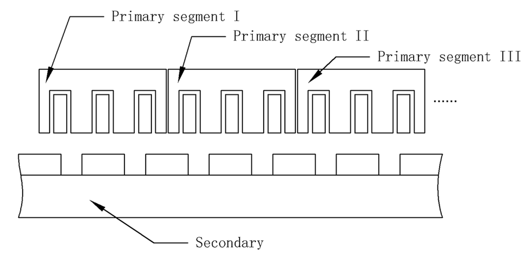
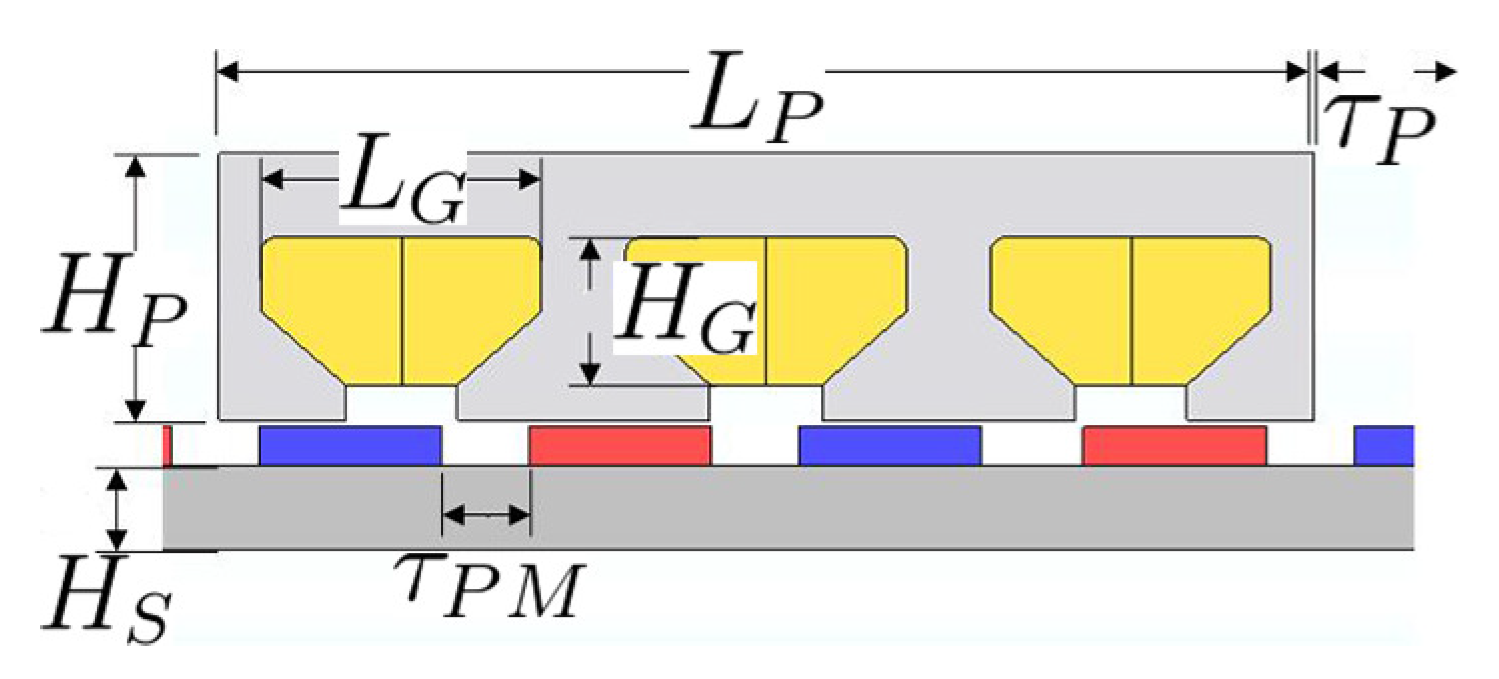
2.1. Segmented Structure

The segmented structure topology of the permanent-magnet linear generator is shown in Figure 1. The primary is divided into multiple segments. The primary segment I has the fewest coil turns and the thickest wire. The number of turns in primary segment II increases, and is subject to the slot area; the wire diameter decreases. By analogy, the number of turns in other segments increases and the wire diameter decreases. When the wave height is low, all the primary segments are put into operation to increase the voltage which ensures that the generator can deliver the available power at low velocity. The coil current is also low due to the low input power, which reduces its impact on the increase in copper loss. As the wave height increases, the primary segments are gradually cut out. With the increase in input power, the coil current increases. Cutting off the thin coils can reduce the copper loss. In addition, the direct-driven WECs have a lower electrical frequency, thus, the iron loss is always lower.
Considering effective use of the primary generator, it is necessary to fill as many wires as possible into the primary slot. The number of turns N is limited by the wire diameter, slot area, and the fill fact which is shown in (1).
N = S s l o t · K F i l l S w i r e
where S s l o t is the slot area, K F i l l is the fill factor and S w i r e is the cross-sectional area of wire.
Every segment has a similar fill factor and slot area. The number of coil turns should satisfy the following ratio, which is related to the slot area and square of the wire diameter as (2).
N 1 : N 2 : : N n = S s l o t 1 d n 2 : S s l o t 2 d n 1 2 : : S s l o t n d 1 2
where d is the wire diameter.

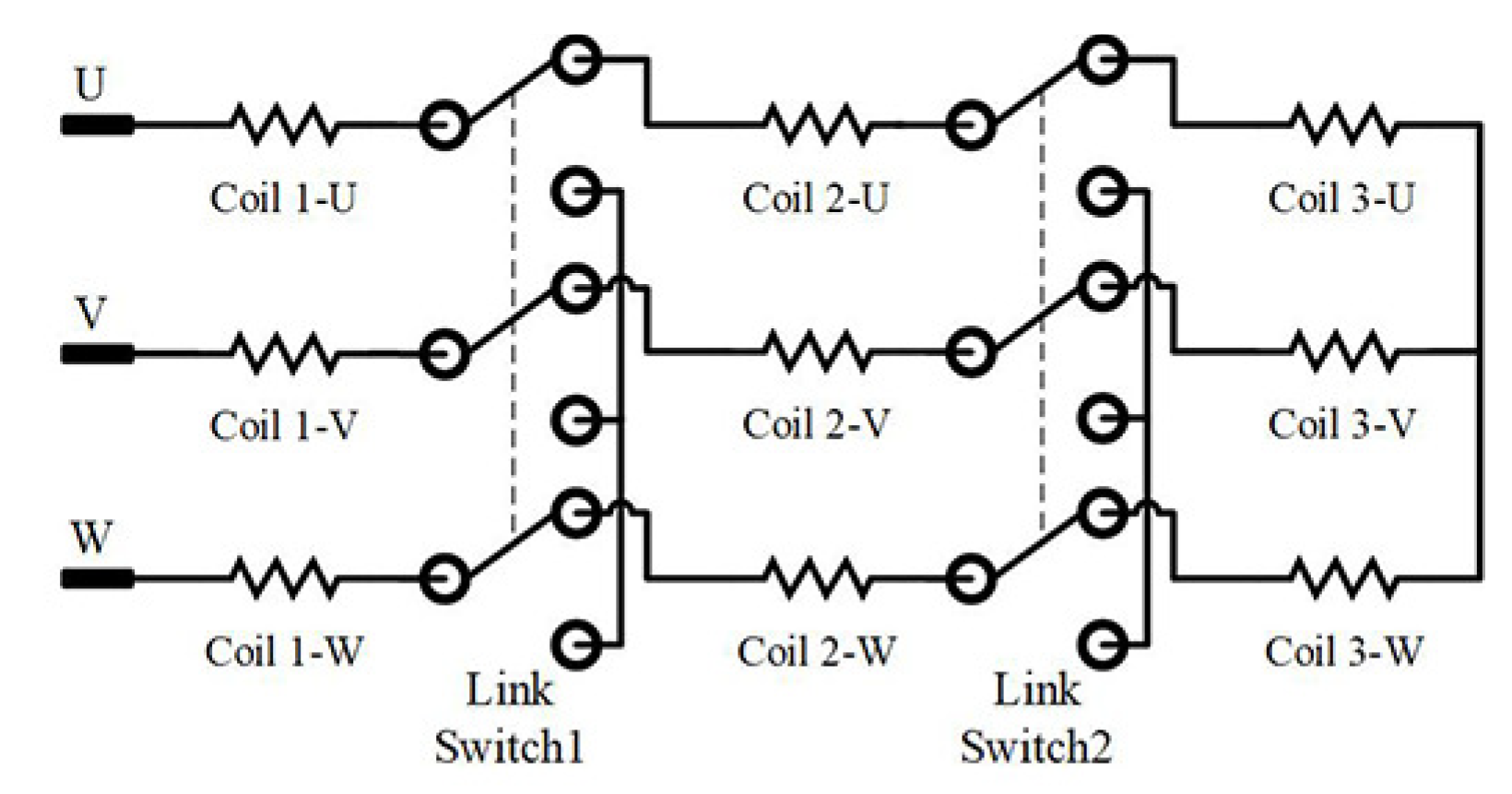
2.2. Coil Connection

Connection between coils of each primary segment is shown in Figure 2. Coil 1 is the coils of primary segment I and coils 2 and 3 are the coils of primary segments II and III, respectively. When the power input increases, the order of coils cutting off is from 3 to 1. Each segment coil is connected to the rear segment coils or three phase Y, connecting the center point via a single-pole double-throw relay or power electronics. Since all primary segments share one secondary, there is no phase difference between coils 1, 2, and 3. Each segment coil can be directly connected in series.
The statement of the switch can be judged by the coil current. According to the current feedback, the switch performs the corresponding action, as shown in the flow chart of Figure 3.

3. Mathematical Model

3.1. Wave Energy Resource

According to linear theory of ocean surface waves, the wave length energy flux density P can be calculated as (3)
P = ρ g 2 64 π H m 0 2 T ( 0.5 k W m 3 · s ) H m 0 2 T
where ρ is the water density, g is the acceleration by gravity, H m 0 is the significant wave height and T is the wave energy period. More recently, significant wave height is calculated from measured wave displacement.
The above formula states that the wave power is proportional to the wave energy period and to the square of the wave height. Significant wave height can approximately be the RMS value of the observed wave displacement. In a particular sea area, the ratio shown in (4) of wave length L and wave displacement h is close to a constant C, which is related to the depth of water.
L h C
In deep water (deep water approximation is valid if the water depth is much greater than the wave length), the dispersion relation of ocean waves can be expressed as follows:
ω 2 g = 2 π L , ω = 2 π T w
where ω is the angular frequency and T w is the wave period.
Substituting (4) and (5) into (3), a relationship between wave power and wave height can be found.
P H m 0 2.5
With the above relationship, the wave energy density is nearly proportional to the cube of the wave height. Combined with the characteristics of the China sea [17], the wave height in winter is about 2–3 times higher than in summer, which means that the difference between the energy density of waves in the two seasons is about 5.7–15.6 times.

3.2. No-Load Status

According to the characteristics of the linear generator structure, it is assumed that the flux linkage per phase can be expressed by (7).
Ψ = N Φ 0 s i n 2 π p v t + 2 n π 3
where N is coil turns, Φ 0 ( t ) is the fundamental magnetic flux per phase, p is pole number, v is secondary velocity, n is 1, 2, and 3 for U, V, and W phase respectively.
The no-load EMF is the time derivative of the flux linkage which is shown in (8). Therefore, the relationship between the no-load EMF peak E 0 , velocity and coil turns is shown in (9).
e = d Ψ d t = 2 π v N Φ 0 P c o s 2 π p v t + 2 n π 3
E 0 N v

3.3. Load Status

According to the dual reaction theory, the generator voltage equation is shown as (10).
U = E 0 + I r + j I X 1 + j I d X a d + j I q X a q
where U is the load voltage, E 0 is the no-load EMF, I is the current in the armature coil which can be decomposed into the direct axis component I d and the quadrature axis component I q , r is the resistance in the armature, X 1 is the inductance in the armature, X a d and X a q are armature reaction reactance in the direct axis and quadrature axis, respectively.
The thrust equation can be expressed as (11).
F e m F i n = J d v d t + f v
where F e m is the electromagnetic damping, F i n is the wave thrust, J is the secondary inertia and f v is the friction damping.
The calculation method of F e m can be derived from the relationship between the power and the force of linear motion.
F e m v = U I + P i r o n + P c o p p e r
where P i r o n is the iron loss and P c o p p e r is the copper loss.
The copper loss accounts for a large proportion of losses in this type of linear generator. Copper loss can be calculated as (13).
P c o p p e r = I 2 r = I 2 k L S w r i e
where k is the resistivity and L is the wire length.
The generator efficiency can be calculated by (14).
η = U I F i n v

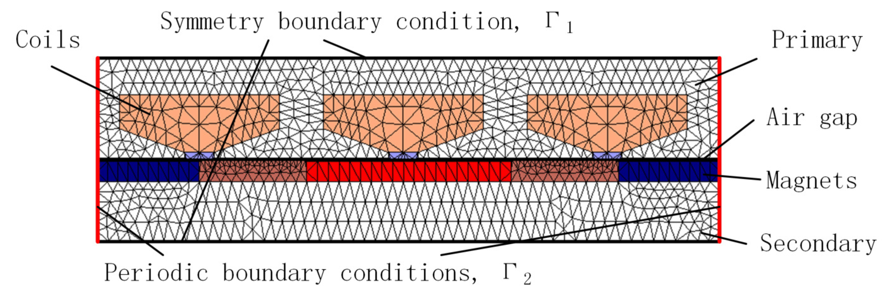
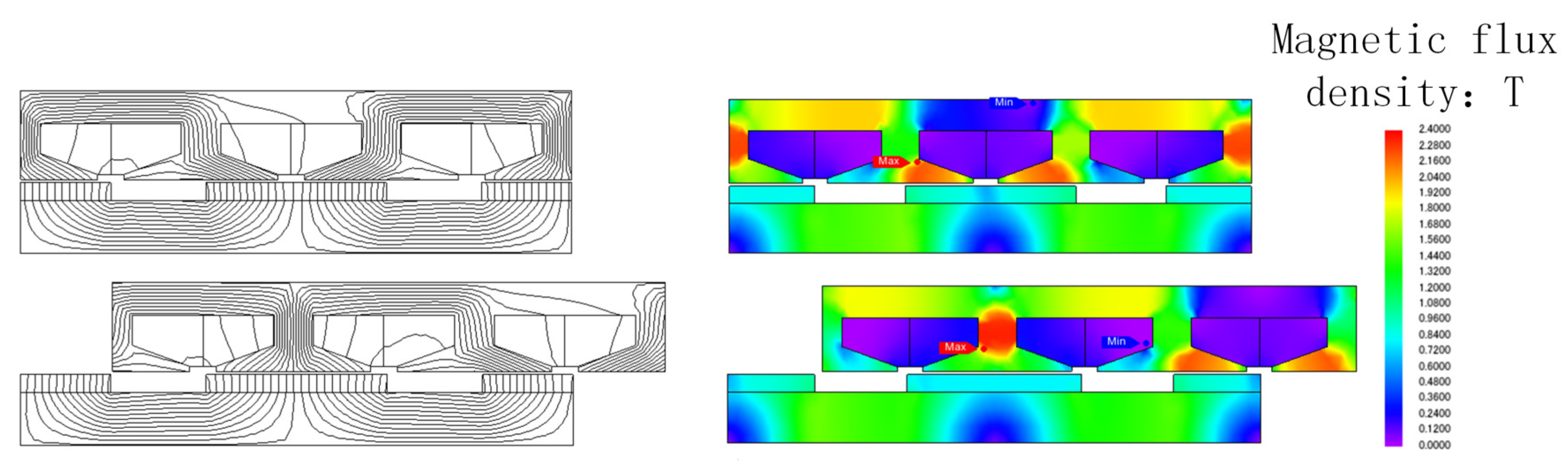
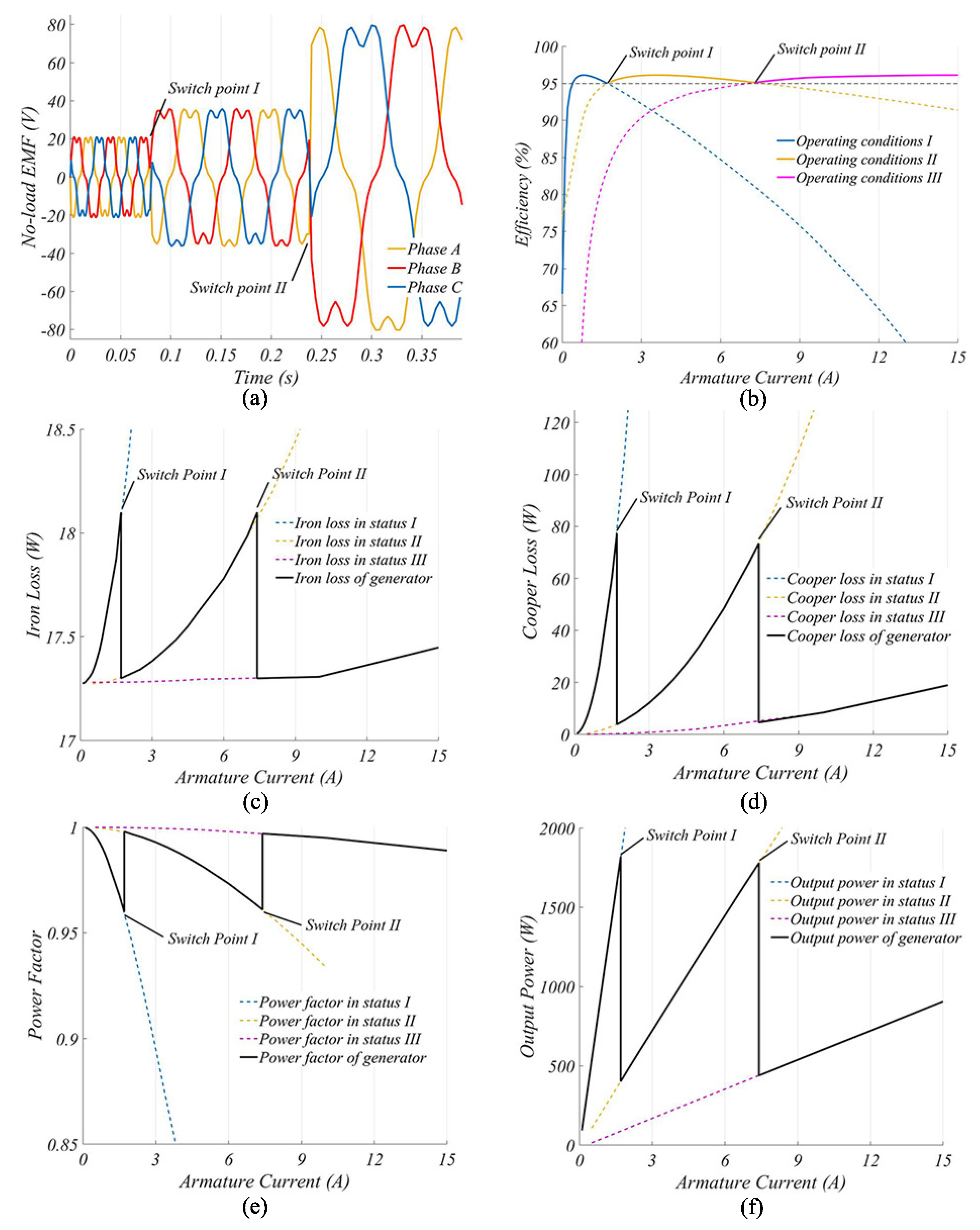
4. Simulation and Result

To obtain the load operation characteristics of the generator, a numerical method can be used for analysis. The analytical solution of electromagnetic field problems in the generator requires the boundary value problems to be solved for partial differential equations. The finite element method is employed here. Since the primary and secondary structures of different generator segments are the same, it is only necessary to establish one segment model and obtain the load characteristics of different segments by changing the winding parameters. Also, due to the particularity of the linear generator, periodic boundary conditions can be used to simplify the model, as shown in Figure 4.
The differential form of Maxwell’s equations gives the expression of the magnetic vector potential of the magnetic field as (15).
× H = × B μ = × ( × A ) = J
where H is magnetic strength, B is magnetic flux density, A is magnetic vector potential and J is current density.
After simplifying the model into a 2-D plane as Figure 4, (15) can be rewritten as (16) in a no-current region and (17) in a current region.
2 A z 1 x 2 + 2 A z 1 y 2 = 0
2 A z 0 x 2 + 2 A z 0 y 2 = μ 0 J ( x )
The Galerkin method is used to discretize the above equations. The nonlinear equations can be obtained as (18)
( [ K ] + [ C ] ) A = F
where [ K ] , [ C ] is the coefficient matrix, F is the column vector of current density and A is the magnetic vector potential to be determined.
The main dimensions of the generator are shown in Figure 5. The specific parameters in the FEM model are shown in Table 2. The generator is divided into three segments. The number of turns in each segment is 40, 120 and 552. The coil wire diameters are 3 mm, 1.5 mm, 0.71 mm. In this model, the fill factor of each segment is close to 73.5%. Since the coils are connected in series, the generator coil resistance is 0.056 Ω , 0.712 Ω , and 14.512 Ω , respectively, under different operation conditions.
By FEA, the magnetic flux density distribution is shown in the flux line and contour plot in Figure 6. The tooth magnetic density peak is approximately 1.8 T.
The no-load EMF is shown in Figure 7a. Before the switch point I, the secondary velocity is 2.5 m/s. In this status, only segment I is in operation. At this time, due to the fewer turns of coils, the no-load EMF is lower than the other operation status, the peak value of which is 21 V. After switch point I, the wave power input decreases and the secondary velocity decreases to 1.5 m/s. In this status, segment II is put into work. Even in the case of deceleration, the no-load EMF peak increases to 33 V due to the increase in coil turns. After switch point III, the wave power input decreases again and the secondary velocity decreases to 0.5 m/s. In this status, all the segments are put into operation, resulting in a no-load EMF peak of up to 81 V.
Under the load condition, the generator efficiency characteristics are shown in Figure 7b. The dotted line shows the efficiency curve of each segment when working independently. The solid line is the efficiency after switch intervention. When the armature current is less than 1.7 A, the efficiency is much higher with all segments working. After switch point I, the efficiency drops dramatically. By cutting out segment III, higher efficiency can be maintained. When the armature current is between 1.7 A and 7.4 A, segments I and II work together, which is more efficient. After switch point III, the efficiency drops again. Segment II needs to be cut out to maintain higher efficiency. Overall, the efficiency of the segmented linear generator is higher than 95% in a global scope.
Figure 7c–e shows the iron loss, copper loss and power factor, respectively. Due to the low operation velocity of the linear generator for WECs, the iron loss is basically maintained below 20 W, which means that as the armature current increases, the main reasons for the decrease in the generator efficiency are copper loss and power factor. Without switching, the copper loss increases rapidly but the power factor decreases rapidly as armature current increases. By segmenting and rationally switching the connections between segments, the power factor, and copper loss can be pulled back to a reasonable range, which allows the generator to maintain a higher output efficiency over a wider current range.
After switching, several segments are cut off, which makes the terminal voltage drop suddenly. The inductive generator coils prevent the current from abruptly changing, which leads to a decrease in output power. Then, the electromagnetic damping is reduced below the wave thrust, which makes the secondary velocity increase. The current and terminal voltage will rise simultaneously until a new thrust equilibrium state is reached. The output power in this process is shown in Figure 7f.

5. Conclusions and Discussion

In this paper, the segmented structure and control method of the permanent-magnet linear generator were introduced. Each segment has the same primary structure and shares one secondary structure. However, they differ in terms of the number of turns of coils and the wire diameter. Different segment coils are connected in series. By controlling the switching of each segment, the range of efficient energy capture can be widened.
When the armature current increases, the power factor decreases, and the copper loss increases, which results in a decrease in the efficiency of the linear generator for WECs. Combined with a reasonable switching control method, a segmented permanent-magnet linear generator can increase the turns of coils at lower the operating velocity, which helps to increase the terminal voltage. As the armature current increases, cutting out specific segments can help to reduce the copper loss and increase the power factor, which helps to increase the efficiency of the generator.
The mathematical model and finite element model are presented to verify the correctness of the proposed structure and control method.
However, there remains some room for improvement:
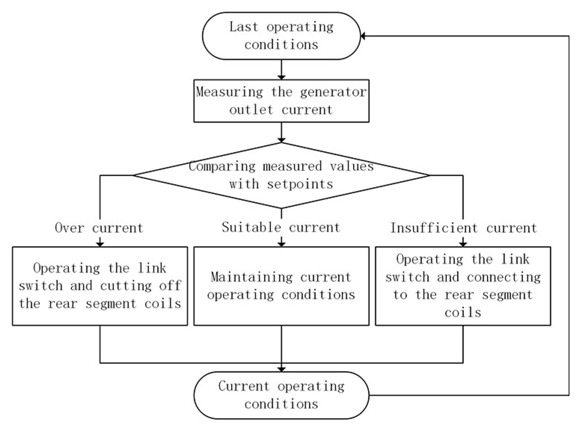
  • The switching control method used in this paper is an open-loop control method, which can still be improved;
  • The end efficient of the linear generator can be considered to improve the accuracy of the results.

Author Contributions

H.W. and S.Q. conceived of the presented idea. S.Q. developed the theory, performed the computations and verified the analytical methods. All authors discussed the results and contributed to the final manuscript.

Funding

This research was funded by National Key Research and Development Program of China No. 2018YFB1501905-04, National Natural Science Foundation of China, NSFC-RCUK-EPSRC No. 51761135014 and the Strategic Priority Research Program of Chinese Academy of Sciences, Grand No. XDA01020304.

Conflicts of Interest

The authors declare no conflict of interest.

References

  1. Boyle, G. Renewable Energy; Boyle, G., Ed.; Oxford University Press: Oxford, UK, May 2004; p. 456, ISBN-10 0199261784, ISBN-13 9780199261789. [Google Scholar]
  2. Cruz, J. Ocean Wave Energy: Current Status and Future Prespectives; Springer Science & Business Media: Berlin/Heidelberg, Germany, 2007. [Google Scholar]
  3. Antonio, F.D.O. Wave energy utilization: A review of the technologies. Renew. Sustain. Energy Rev. 2010, 14, 899–918. [Google Scholar]
  4. Kamranzad, B.; Etemad-Shahidi, A.; Chegini, V. Assessment of wave energy variation in the Persian Gulf. Ocean Eng. 2013, 70, 72–80. [Google Scholar] [CrossRef] [Green Version]
  5. López, I.; Andreu, J.; Ceballos, S.; de Alegría, I.M.; Kortabarria, I. Review of wave energy technologies and the necessary power-equipment. Renew. Sustain. Energy Rev. 2013, 27, 413–434. [Google Scholar] [CrossRef]
  6. Falcão, A.F.; Henriques, J.C.; Gato, L.M. Self-rectifying air turbines for wave energy conversion: A comparative analysis. Renew. Sustain. Energy Rev. 2018, 91, 1231–1241. [Google Scholar] [CrossRef]
  7. Margheritini, L.; Vicinanza, D.; Frigaard, P. SSG wave energy converter: Design, reliability and hydraulic performance of an innovative overtopping device. Renew. Energy 2009, 34, 1371–1380. [Google Scholar] [CrossRef]
  8. Sheng, S.; Wang, K.; Lin, H.; Zhang, Y.; You, Y.; Wang, Z.; Chen, A.; Jiang, J.; Wang, W.; Ye, Y. Model research and open sea tests of 100 kW wave energy convertor Sharp Eagle Wanshan. Renew. Energy 2017, 113, 587–595. [Google Scholar] [CrossRef]
  9. Henderson, R. Design, simulation, and testing of a novel hydraulic power take-off system for the Pelamis wave energy converter. Renew. Energy 2006, 31, 271–283. [Google Scholar] [CrossRef]
  10. Abdelkhalik, O.; Zou, S. Control of small two-body heaving wave energy converters for ocean measurement applications. Renew. Energy 2019, 132, 587–595. [Google Scholar] [CrossRef]
  11. Falnes, J. Ocean Waves and Oscillating Systems: Linear Interactions Including Wave-Energy Extraction; Cambridge University Press: Cambridge, UK, 2002. [Google Scholar]
  12. Waters, R.; Rahm, M.; Eriksson, M.; Svensson, O.; Stromstedt, E.; Bostrom, C.; Sundberg, J.; Leijon, M. Ocean wave energy absorption in response to wave period and amplitude-offshore experiments on a wave energy converter. IET Renew. Power Gener. 2011, 5, 465–469. [Google Scholar] [CrossRef]
  13. Ekergård, B. Full Scale Applications of Permanent Magnet Electromagnetic Energy Converters: From Nd2Fe14B to Ferrite. Ph.D. Thesis, Acta Universitatis Upsaliensis, Uppsala, Sweden, 2013. [Google Scholar]
  14. Lejerskog, E. Linear Wave Energy Converter: Study of Electromagnetic Design. Ph.D. Thesis, Uppsala Universitet, Uppsala, Sweden, 2014. [Google Scholar]
  15. Svensson, O. Experimental Results from the Lysekil Wave Power Research Site. Ph.D. Thesis, Acta Universitatis Upsaliensis, Uppsala, Sweden, 2012. [Google Scholar]
  16. Wu, B.J.; Diao, X.H.; You, Y. 10 kW floating point absorber direct drive wave energy device. Ocean Technol. 2012, 31, 68–73. [Google Scholar]
  17. Wan, Y.; Zhang, J.; Meng, J.; Wang, J. A wave energy resource assessment in the China’s seas based on multi-satellite merged radar altimeter data. Acta Oceanol. Sin. 2015, 34, 115–124. [Google Scholar] [CrossRef]
Figure 1. Segmented structure topology for FL the permanent-magnet linear generator.
Jmse 07 00101 g001
Figure 2. Coils connection between primary segments.
Jmse 07 00101 g002
Figure 3. Coils switching method.
Jmse 07 00101 g003
Figure 4. Simplified finite element model of the linear generator.
Jmse 07 00101 g004
Figure 5. Main dimensions of the generator.
Jmse 07 00101 g005
Figure 6. Magnetic field distribution.
Jmse 07 00101 g006
Figure 7. Simulation result of FL the segmented permanent-magnet linear generator. (a) No-load EMF; (b) Efficiency; (c) Copper loss; (d) Iron loss; (e) Power factor; (f) Output power.
Jmse 07 00101 g007
Table 1. Wave height of FL the South China Sea in different seasons.
SpringSummerFallWinter
(March, April, May)(June, July, August)(September, October, November)(December, January, February)
Average0.9 m1 m1.4 m2.5 m
Maximum1.5 m1.5 m3 m6 m
Annual average1.5 m
Table 2. Main Parameters of FL the FEM Model.
DescriptionValueExp
SecondarySecondary core height12 [mm] H s
Permanent-magnet spacing 12.5 [mm] τ P M
Permanent-magnet size 5.5 × 26 × 110 [mm]
PrimaryPrimary segment length168 [mm] L P
Primary height50 [mm] H P
Primary segment spacing39 [mm] τ P
Groove length (Uneven)21 [mm] L G
Groove height (Uneven)40 [mm] H G
Air gap length1 [mm]
Stack height110 [mm]
Primary SegmentITurns40
Wire diameter3 [mm]
Resistance of coil 0.056 [ Ω ]
Fill factor 73.74 [ % ]
IITurns120
Wire diameter 1.5 [mm]
Resistance of coil 0.656 [ Ω ]
Fill factor 73.48 [ % ]
IIITurns552
Wire diameter 0.71 [mm]
Resistance of coil 13.8 [ Ω ]
Fill factor 73.26 [ % ]

