1. Introduction
The unwanted attachment and accumulation of organisms on immersed artificial surfaces, referred to as biofouling, is a widespread problem with impacts across multiple sectors [
1,
2,
3,
4,
5]. Marine biofouling in particular can have substantial economic impacts, increasing fuel consumption and, therefore, voyage costs for the global shipping industry [
2,
6]. To date, most successful coatings designed to combat marine biofouling have been based on biocidal technologies [
7], but their widespread use has resulted in release of toxic compounds (biocides), some of which can have negative environmental effects. Therefore, there is a need for novel, effective, and non-toxic alternatives to biocide-based coatings [
8,
9]. Novel materials and approaches are required that would ideally be low-cost, non-toxic to non-target organisms, effective over multi-annual timescales, and capable of flexible and widespread application to infrastructure such as the marine shipping fleet [
10].
Oil-infused polymers are one promising group of materials [
11,
12,
13]. These are made by exposing bulk polymeric materials such as fluoropolymers or polydimethylsiloxanes (PDMS) to an excess of a chemically-matched oil, such as silicone or perfluorinated oils. The polymers absorb the oil, leaving a thin liquid layer on the material surface and a reservoir of oil in the bulk polymer. This allows oil to diffuse to the interface and replenish the surface liquid layer as it becomes depleted. Recently introduced Slippery Liquid-Infused Porous Surfaces (SLIPS) are non-adhesive coatings based on this concept [
11,
13,
14]. These are capable of repelling a range of contaminants or fouling, including ice, blood, and bacteria [
12,
15,
16] and are reportedly highly effective at resisting bacterial adhesion under both static and flow conditions. Therefore, they appear to have the potential for widespread commercial application [
16].
The ability to easily add functionality or tailor coating properties by generating surface relief (or surface topography) in a controlled manner may further expand the application of these coatings. For example, surface relief structures in fluoropolymers may increase control over wettability, oil retention, or cellular adhesion, with applications for antifouling coatings [
14] or liquid repellent coatings [
12]. Surface micro- or nano-topographies are often found in nature, where they may provide enhanced surface functionality. Bio-inspired liquid repellent surfaces are of continued interest due to their unique properties [
12,
17,
18,
19,
20,
21]. Omniphobic surfaces, for example, have the capability to repel a wide variety of liquids, including both water and oil, using a combination of surface topography and surface chemistry [
14], and could be used as antifouling coatings [
12,
19]. Engineered surface patterns have been shown to have marine antifouling properties, but typically need to be optimized to deter particular marine fouling organisms [
22].
Given the diverse nature of potential fouling organisms, particularly in the marine environment, it is challenging to create antifouling technologies that show broad-spectrum effectiveness. It is therefore likely that successful non-toxic antifouling solutions will require a combination of approaches. The aim of this research was to combine the two approaches described above to create liquid-infused surfaces embossed with surface structures. It has previously been shown that a photo-embossing process can be used to create surface relief structures in fluoropolymer coatings in a controllable fashion [
23]. Here, we demonstrate that perfluorinated oil-infused fluorinated meth(acrylate) coatings with tuneable surface topography can be created using this photo-embossing process. The process is currently very facile for relatively small surface areas (25 mm × 75 mm surface areas for example) and uses a one-pot method with (perfluorinated) solvents to fabricate structured fluorogel coatings. We investigated the marine antifouling performance of such materials with a hexagonal surface pattern as a proof of concept using a variety of marine laboratory assays.
3. Preparation of Samples for Antifouling Tests
Glass substrates (3 cm × 3 cm × 1 mm) were cleaned by sonication in acetone (15 min) followed by treatment in an UV−ozone photoreactor (Ultra Violet Products, PR-100, 20 min). The surface of the glass substrates was subsequently modified by spin-coating a 3 (trimethoxysilyl) propyl methacrylate solution (1% v/v solution in a 1:1 water-isopropanol mixture) on the activated glass substrate for 30 s at 3000 rpm. After curing for 10 min at 110 °C, the substrates were ready for use.
Glass substrates (microscope slides, 2.5 cm × 7.5 cm) were sanded with sandpaper (grit size: 120) and sonicated in acetone for 15 min, followed by treatment in an UV-ozone photoreactor (Ultra Violet Products, PR-100, 20 min). An adhesion layer (‘tie coat’) specifically designed for marine coatings (Veridian, International Paint Ltd, Gateshead, UK) was applied to the glass slides using a doctor blade with a gap height of 100 µm, and left to dry for 1 h prior to use.
Flat coatings were made by drop casting 500 µL of the monomer and initiator mixture onto the prepared surfaces. The samples were exposed, in a nitrogen atmosphere, to UV light (EXFO Omnicure S2000 lamp) for 120 s with an intensity of 98 mW cm
−2 in the UVA range (315–400 nm) as measured by an Opsytec radiometer RM-12. Structured coatings were made using a soda-lime glass chromium oxide photomask (
Figure 2C), with hexagonal cut-outs (7.5 µm sides) spaced 30 µm apart. A total of 500 µL of the monomer and initiator mixture was drop cast onto each of the prepared slides and the photomask was attached on top of the samples using 3 layers of double-sided tape (Tesa, photostrip, thickness: ~100 µm) at both ends. This formed a glass cell with a thickness of ~300 µm, which was then exposed to UV light in a nitrogen atmosphere for 120 s (same conditions as for flat coatings) through the photomask. Subsequently, the photomask was removed and the sample was illuminated with UV for 120 s to polymerize any residual monomers. For full details of the photo-embossing procedure, see Kommeren et al., (2016) [
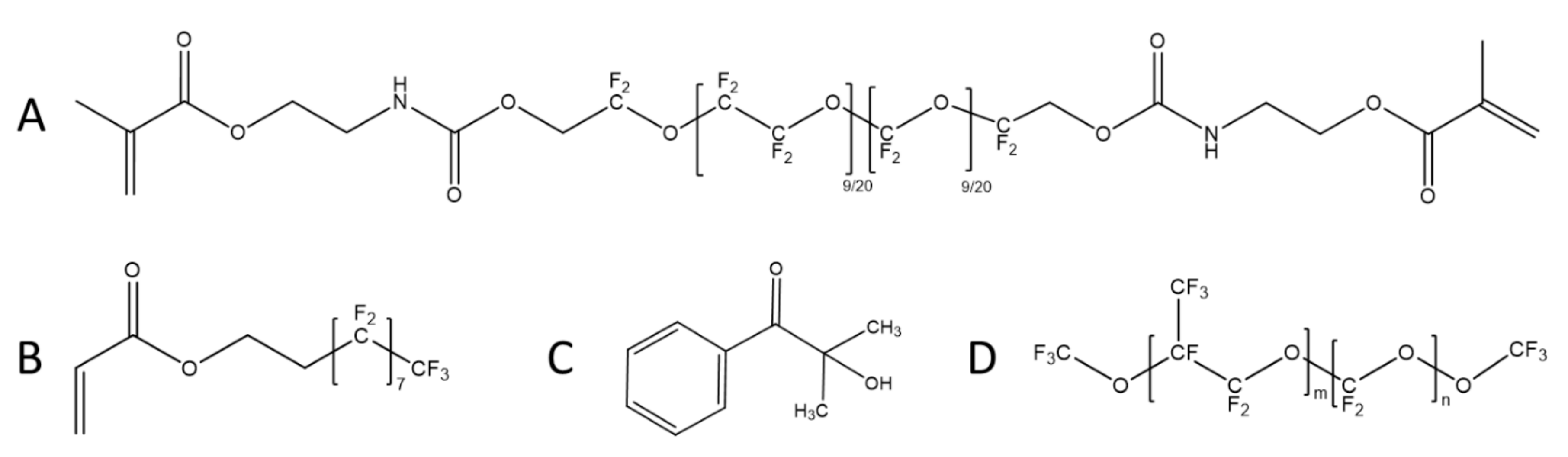
23]. The naming convention for coatings uses F (flat) and S (surface-structured), along with the vol% of PPFP-18 present in the monomer mixture (
Table 1). For example, F20 is a flat coating with 20vol% of PPFP-18, and S10 is a surface-structured coating with 10vol% PPFP-18.
So that the antifouling and fouling-release performance of the test surfaces could be compared with existing materials, additional glass microscope slides were also prepared as ‘standards’; these were coated with polydimethyl siloxane (PDMS, Dow Corning 3-0213, Dow Corning Corporation, Auburn, MI, USA) and two commercial fouling-release products Intersleek® 757 and Intersleek® 1100SR (International Paint Ltd, Gateshead, UK). These surfaces were prepared by International Paint Ltd, in accordance with manufacturer’s instructions. All surfaces (standard materials and test surfaces) used in biological assays were subjected to a toxicity screening procedure prior to use in laboratory or field assays. This aimed to ensure that there were no residual compounds (e.g., solvents, photo-initiators) which might leach out of the surfaces and affect survival or settlement of larvae of the barnacle Balanus amphitrite. All surfaces were also pre-leached in recirculating filtered and de-ionized water for a minimum of seven days.
4. Materials Characterization
The dimensions of the resulting surface relief structures were measured using white light interferometry (Fogale Nanotech Zoomsurf 3D) and with 3D optical profilometry (Brüker DektakXT with a needle force of 1.5 mg). A width of 120 µm was measured with a speed of 12 µm s−1 over length of 60 µm at 1 µm intervals for optical profilometry. Optical microscopy images were generated using a Leica DM2700M with a 20× objective. The shape of the non-perfluorinated oil infused surface relief structures was also confirmed by scanning electron microscopy (SEM, Jeol JSM-5600). Samples were prepared for SEM by adhering the fluoropolymer films to a 15 mm aluminum stub with carbon tape before sputter-coating with Au (approximately 15 nm layer thickness). Static water contact angles of 3 µL droplets of de-ionized water were measured using a Krüss OCA 30 optical contact angle measuring analysis system.
4.1. Biofilm Settlement and Ease-of-Removal Assay
Biofilms were developed on test coatings using a biofilm culturing reactor (Longyear et al., in [
24]) consisting of a 120 cm × 165 cm × 30 cm flow-through seawater tank fed with sand-filtered natural seawater maintained at 19.5 (± 1) °C, 35 (± 1) psu, and pH 7.8. Eight slides of each test coating (excluding F40 and S40, which were not subjected to this test), and 8 Intersleek® 1100SR reference slides, were placed in a 9-channel flume set on a stand above the tank, in natural light conditions, which allowed the cultured seawater to be flowed over the samples, assisting removal of non-adhered fouling. The samples were cultured for 6 weeks to allow biofilm development. Samples were photographed after 2, 4, and 6 weeks and % cover of biofilm was measured using ImageJ, Version 1.46r [
25].
After 6 weeks, 4 replicate slides of each coating were used for a cleaning test with a linear washability tester (Elcometer 1720 Abrasion and Washability Tester, Elcometer, Manchester, UK). The fouled samples were placed flat on the bottom plate of the tester. The biofilm was kept hydrated prior to the cleaning test by immersion in seawater. A damp sponge (thoroughly wetted with tap water and gently squeezed to remove excess water) was used, and attached to the abrader. The sponge passed over the surface of the coating at a rate of 4 cycles per minute; one cycle was defined as the sponge passing over the coating from left to right and then back. No additional weight was added to the sponge attachment, so the downward pressure of the sponge was the combined weight of the attachment and sponge. Slides were photographed before and after cleaning and the percent biofilm cover was measured. The proportion of biofouling removed was calculated for each slide.
4.2. Diatom Initial Adhesion and Ease-of-Removal Assay
Three replicate slides of each test coating, PDMS, and clean glass were equilibrated in deionized water for 24 h, and then in 30 psu artificial seawater (ASW; Tropic Marin, Wartenberg, Germany) for a further 24 h. Laboratory cultures of the diatom
Navicula incerta were harvested while in log growth phase, re-suspended in 0.22 µm-filtered ASW, and diluted to an optical density of 0.02 at 660 nm. Test slides were placed in quadriPERM dishes (Sarstedt, Nümbrecht, Germany) and 10 mL of diatom suspension was added to each dish compartment. Dishes were left in ambient light conditions at room temperature for 2 h. To remove unattached cells, all quadriPERM dishes were immersed in ASW, gently agitated, and placed on an orbital shaker at 60 rpm for 300 s. Three replicates of each surface were then exposed to hydrodynamic shear (flow rate = 5.7 m s
−1, wall shear stress = 32 Pa) for 300 s in a turbulent flow cell (similar to that described in [
26,
27]). All slides were then fixed using 2% glutaraldehyde in ASW and air-dried. Diatom cell density was measured under fluorescence microscopy (Leica DMi8 Leica Microsystems GmBH, Wetzlar, Germany, illumination at 546 nm, excitation / 590 nm, emission), taken as the average of 20 manual counts of the number of diatoms per field of view on each replicate slide, divided by the measured area of the field of view (0.6 mm
2). Percent removal under shear was calculated as the percent difference between cell density on shear-exposed and non-exposed slides.
4.3. Barnacle Cyprid Settlement Assay
Adult barnacles,
Balanus amphitrite (=
Amphibalanus amphitrite), were cultured, induced to release nauplii, and reared to the cyprid stage following the methods of Hellio et al., [
28,
29], except that all stages were carried out in 32 psu ASW, and nauplii were reared on
Tetraselmis suecica. Six slides of each test coating and 7 slides of PDMS were placed into quadriPERM dishes. A 750 µL droplet of 0.22 µm-filtered ASW was pipetted onto the surface of each slide. Cyprid larvae (20 ± 2) were added to each droplet in a minimal volume of ASW. Samples were incubated in the dark at 28 °C, and settled cyprids on each replicate were counted after 48 h.
4.4. Juvenile Barnacle Ease-of-Removal Assay
Barnacles were settled on surfaces as above, except that more cyprids (>50) were used in a greater volume of filtered ASW. In addition to the test coatings, 12 PDMS-coated slides were included, along with 6 slides coated in Intersleek® 757, 6 slides coated in Intersleek® 1100SR, and 6 uncoated glass slides. Samples were incubated for 48 hours at 28 °C in the dark, and then gently rinsed to remove unattached cyprids. All quadriPERM dish wells were flooded with ASW and a few drops of T. suecica suspension, and left for a further 72 h. The numbers and locations of all metamorphosed barnacles on each slide were recorded. All slides were then exposed to hydrodynamic shear (flow rate = 10.3 ms−1, estimated wall shear stress = 130 Pa) for 120 s in the same flow cell used for the diatom experiment. After exposure, any remaining barnacles were counted, checking recorded locations for remaining base plate fragments. The presence of base plate fragments indicated that the barnacle had broken up under force (‘cohesive failure’) rather than being cleanly removed, and any such barnacles were not counted as having been removed from the surface.
4.5. Critical Removal Stress of Adult Barnacles
Barnacles were settled on test coatings, glass slides, and slides coated with PDMS and Intersleek® 757, as above. Settled barnacles were raised on a mixed diet of
T. suecica and
Artemia sp. until they reached a base plate diameter of >5 mm, removing individuals as necessary to keep clear space around all adult barnacles. An automated ‘push-off’ apparatus [
30] was then used to measure the force required to detach individual barnacles from coating surfaces, and to calculate the critical removal stress (CRS; detachment force divided by base plate area) for each barnacle. CRS measurements were only recorded where barnacles were cleanly removed, with no signs of cohesive failure (as indicated by baseplate fragments remaining on test surfaces). Data from previous CRS measurements for PDMS and Intersleek® 757 were included to increase sample size. Removed barnacles were inspected for attachment anomalies, including baseplate deformities (e.g., ‘cupped’ morphology as described by [
31] and presence of thick ‘gummy’ adhesive layers).
4.6. Data Analysis
Data analyses were conducted using SigmaPlot v.12.0 (Systat Software Inc., San Jose, CA, USA). Biofilm coverage data (for each immersion time), cyprid proportional settlement data (arcsine-square root transformed to equalize variances), juvenile barnacle percent removal data, adult barnacle CRS data (square root transformed to normalize data and equalize variances), and diatom density/% removal data, were all analyzed for the fluorogel surfaces using two-way ANOVA (with ‘surface type’—flat vs. structured; and ‘oil content’—0% to 40%, as fixed factors), with Holm–Sidak post-hoc tests. Percent coverage data for the biofilm removal test were analyzed using a two-way repeated measures ANOVA with ‘treatment’ (before versus after cleaning test) and ‘surface’ as factors, with Holm–Sidak post-hoc tests.
5. Results
The photo-embossing process successfully generated surfaces with regularly-spaced hexagonal projections (
Figure 3). The mean height of the structures projecting from the surfaces (measured using optical techniques) appeared to decrease with increasing perfluorinated oil content (
Figure 2B). This is likely to be a result of the accumulation of oil in the spaces between the raised hexagons when the oil content is greater than 10% (
Figure 3). When the formulation contains 40 vol% of PPFP-18, the spaces are almost completely filled with the perfluorinated oil, such that the structure is barely visible at the surface (
Figure 3B,E). There appeared to be a depression at the top of each hexagon (
Figure 2A). The cause of this phenomenon is not yet explained, but may arise from monomer diffusion effects; as polymerization and cross-linking occurs in the illuminated areas, monomer mobility may decrease and monomers are polymerized at the edges of the features before reaching the centre.
All experimental surfaces were relatively hydrophobic (
Table 1), with contact angles over 100° in all cases. Contact angles for structured surfaces were higher at all PPFP-18 volume percentages. Addition of perfluorinated oil appeared to lower the contact angle relative to oil-free surfaces, although only at higher volume percentages (40% for the flat surfaces, and 20% and 40% for the structured surfaces).
5.1. Biofilm Accumulation and Cleaning Test
After six weeks immersion in the biofilm culturing reactor, extensive biofilm had formed on all fluorogel surfaces (>60% cover on all surfaces except for F20 and Intersleek® 1100SR,
Figure 2A). The effect of perfluorinated oil content on biofilm cover depended on the type of surface (
Table S1; ANOVA, significant interaction between factors ‘surface type’ and ‘oil content’,
F = 9.54,
df = 3,
p < 0.001). F20 had significantly less biofilm than flat surfaces with lower oil content (Holm–Sidak, all comparisons
p < 0.01) while there was no significant variation among the lower oil content flat surfaces (F0, F5, F10; Holm–Sidak, all comparisons
p > 0.05), or among any of the structured surfaces (S0-S20; Holm–Sidak, all comparisons
p > 0.05). Biofilm coverage was generally less on flat surfaces (Holm–Sidak,
p < 0.05 for all pairwise comparisons between flat and structured surfaces with equal perfluorinated oil content, except F5 versus S5, where
p = 0.822). Patterns of biofilm coverage amongst test surfaces were qualitatively similar at 2 and 4 weeks immersion (
Table S2, Figure S1).
There was significant variation between surfaces in the cleaning test (RM ANOVA, factor ‘Surface’, F = 4.727,
p = 0.002); surface F20 differed significantly from all other fluorogel surfaces (
Table S3, Holm–Sidak,
p < 0.05 for all contrasts including surface F20). F20 had lower initial biofilm cover, lower biofilm cover after cleaning, and higher percent removal during cleaning, compared to all other fluorogel surfaces (
Figure 4B,C). However, this does appear inferior to Intersleek® 1100SR, which showed very low cover prior to the removal test (~20%, compared to ~60% on F20), and effectively no biofilm coverage after the cleaning test (~100% removal of biofilm,
Figure 4C).
5.2. Diatom Adhesion and Ease-of Release
Initial settlement density of diatoms differed among fluorogel surfaces (
Table S4; ANOVA, significant interaction term between factors ‘surface type’ and ‘oil content’,
F = 4.318,
df = 4,
p = 0.011). Within each surface type, there was no significant variation in density among the different levels of oil content (
Table S4, Holm–Sidak, all pairwise contrasts,
p > 0.05), while at all levels of perfluorinated oil content there was significantly higher diatom density on the structured surfaces (Holm–Sidak,
p < 0.05). The difference in density between flat and structured surfaces was most pronounced in the absence of perfluorinated oil (surfaces F0 versus S0), and declined with increasing perfluorinated oil content (
Figure 5A).
Diatom settlement density after exposure to shear stress was significantly affected by both surface type (
Table S5; ANOVA, factor = ‘surface type’,
F = 52.823,
df =1,
p < 0.001) and perfluorinated oil content (ANOVA, factor = ‘oil content’,
F = 7.027,
df = 4,
p = 0.001). Settlement density was higher on structured surfaces, and generally on perfluorinated oil-containing surfaces, compared to oil-free surfaces (Holm–Sidak,
p < 0.05, except for 0 vs. 20% oil, where
p > 0.05), although there was no significant differentiation among different levels of oil content for oil-containing surfaces (Holm–Sidak,
p > 0.05 for comparisons among 5, 10, 20, and 40% oil content).
Percent removal of diatoms under shear from perfluorinated oil-containing surfaces was generally low and not significantly different from zero for most of the oil-containing surfaces (
Figure 5B: 95% confidence intervals overlap zero for F5, F10, F40, S10, and S40; confidence intervals for S20 also approach zero). Surface type and oil content had a significant effect on percent removal (ANOVA; factor ‘oil content’,
F = 9.687,
df = 4,
p < 0.001; factor ‘surface type’,
F = 13.149,
df =1,
p = 0.002). Removal was greater from structured surfaces, and from the oil-free surfaces (
Figure 5B;
Table S6; Holm–Sidak,
p < 0.05 for 0% vs. 5%, 10% and 40% oil,
p = 0.065 for 0% versus 20% oil). In comparison, percent removal from PDMS appeared considerably higher (
Figure 5B).
5.3. Barnacle Settlement
Addition of perfluorinated oil had a significant effect on barnacle settlement (ANOVA, factor = ‘oil content’,
F = 23.369,
df = 4,
p < 0.001;
Table S7), while the presence of surface structure had no significant effect (ANOVA, factor = ‘surface type’,
F = 0.731,
df = 1,
p = 0.397). Settlement was lower on surfaces with 20% and 40% oil compared to those with 10% oil or less (Holm–Sidak,
p < 0.001), but there was no significant variation among surfaces with less than 20% oil (Holm–Sidak,
p > 0.9) or between surfaces with 20% and 40% oil (Holm–Sidak,
p = 0.251). Settlement of barnacles appeared to be similar or higher on all test surfaces compared to PDMS (
Figure 6A), indicating that these surfaces had little anti-settlement effect on barnacle cyprids.
5.4. Barnacle Percent Removal (Juveniles)
The effect of perfluorinated oil inclusion on juvenile barnacle percent release differed between the two surface types (
Table S8: The interaction between factors ‘oil content’ and ‘surface type’ was significant,
F = 3.620,
df = 4,
p = 0.012). For structured surfaces, increasing oil content did not increase percent removal of juvenile barnacles under shear stress (Holm–Sidak,
p > 0.05 for all contrasts between structured surfaces S0 to S40). For flat surfaces, percent removal was higher on the surfaces with 20% and 40% oil compared to the surfaces with 10% oil or less (
Figure 6B, Holm–Sidak,
p < 0.05 for all comparisons between F20 or F40 and F0/F5/F10), while there was no significant difference between F20 and F40 (Holm–Sidak,
p = 0.964) or among F0/F5/F10 (Holm–Sidak, all
p > 0.89). Percent removal of juvenile barnacles from the two best-performing surfaces, F20 and F40, appeared to be intermediate between the performance of the two commercial fouling-release coatings, Intersleek® 757 and Intersleek® 1100SR (
Figure 6B). All other test surfaces appeared to perform similarly to PDMS.
5.5. Adult Barnacle Removal
Adhesion strength (CRS) of adult barnacles was significantly affected by both the surface type (
Table S9; ANOVA, factor = ‘surface type’,
F = 18.693,
df = 1,
p < 0.001) and the oil content (ANOVA, factor = ‘oil content’,
F = 40.194,
df = 4,
p < 0.001) of fluorogel surfaces. Barnacles were more strongly adhered to the structured surfaces than to the flat surfaces, and less strongly adhered to surfaces with greater perfluorinated oil content (
Figure 6C;
Table S9). Barnacles on surfaces with 20% and 40% oil required significantly less force to detach than those on surfaces with 10% oil or less (Holm–Sidak,
p < 0.001), while there was no significant variation among surfaces with no oil, 5% oil, or 10% oil (Holm–Sidak,
p > 0.8). The surfaces with 40% oil also had significantly lower CRS than those with 20% oil (Holm–Sidak,
p = 0.006). The two best performing surfaces (F20 and F40) had lower mean CRS than PDMS (
Figure 6C; the 95% confidence intervals for these two surfaces do not overlap with those of PDMS), and F40 had a lower CRS than Intersleek® 757 (the 95% confidence intervals of these two surfaces do not overlap). Oil content also strongly affected the proportion of barnacles that were cleanly removed (leaving no base plate fragments), with 100% clean removal for F20, F40, and S40 (
Figure 6D). There was a greater tendency for barnacle cohesive failure on the structured surfaces, particularly at lower oil loadings. On the highest oil-content surfaces (20–40%) baseplate anomalies were common (
Figure 6E).
6. Discussion
Developing an effective and biocide-free ‘universal’ antifouling material that is equally effective for all applications is challenging. Previous studies have pointed out that materials that successfully resist biofouling are difficult to achieve by surface chemistry or surface structuring alone [
11]. Instead, a suite of approaches that can be tailored to the applications as needed would seem a more pragmatic approach. Here, we provide a ‘blueprint’ for rapid prototyping of lubricant infused perfluoropolyether surfaces incorporating surface structuring. The methods described here allow the creation of surface-structured coatings via a relatively simple UV-curing method, which, in principle, would allow a range of different patterns to be generated. Furthermore, surface-lubricating perfluorinated oil was included via a simple ‘one-pot’ method. Of course, considerable development would be required before such methods were applicable in commercial contexts, but the results here demonstrate the feasibility of using such techniques to create non-toxic antifouling surfaces which combine the two approaches.
In this particular case, the antifouling test results for these prototype surfaces were somewhat mixed. Addition of perfluorinated oil had a clear beneficial impact on the performance of the surfaces in the barnacle assays, but only once a threshold volume percentage of PPFP-18 had been passed. With 10% PPFP-18 or less, the surfaces performed poorly in all barnacle tests; cyprid settlement was very high, and both juvenile and adult barnacles were strongly adhered. At higher levels of oil content, settlement was somewhat reduced, but more importantly, the tenacity of any attached barnacles was much lower. Particularly on the flat surfaces, barnacles were very easily removed, with attachment strengths indicating similar or better fouling-release performance than the commercial silicone elastomer coating Intersleek® 757. Removal of recently metamorphosed barnacles was, however, lower than from the advanced fluoropolymer coating Intersleek® 1100SR. The attachment strengths of adult barnacles could not be compared with Intersleek® 1100SR, since no adult barnacles could be grown on this commercial coating for testing. Nevertheless, to obtain similar fouling-release performance to commercial coatings against attached barnacles is a promising outcome. The low force required to remove barnacles from surfaces with the highest levels of fluorinated oil may partly be explained by the greater occurrence of baseplate anomalies on these surfaces. Abnormal baseplates are often found on barnacles that have settled on fouling-release surfaces [
31] and are associated with weaker attachment [
32]. Unfortunately, while the surfaces had good fouling-release qualities against attached barnacles, they were less effective at preventing barnacle settlement.
Addition of oil also improved the performance of the surfaces in biofilm growth and removal assays, at least for the flat surfaces. Again, there appeared to be a threshold effect, since biofilm coverage and removal did not show any improvement for surfaces with less than 20% PPFP-18 content. One possible explanation for this effect is that at lower perfluorinated oil content levels, the oil remains within the fluoropolymer coating and is not evident on the surface. At levels of 20% and greater, the coatings may be saturated, such that excess oil begins to form a layer on the coating surface. The results of the surface characterization may support this, since (for the structured surfaces) the gaps in the surface pattern do not begin to fill in with fluid at oil content less than 20%, and the measured contact angles do not begin to show any change until at least 20% oil content. While still performing less well than Intersleek® 1100SR in the biofilm tests, the results for the F20 coating still show some promise. Unfortunately, the F40 and S40 coatings were not subjected to the biofilm tests; these may have shown further improvements over the oil-free coatings.
In contrast, the diatom results can be considered somewhat disappointing. However, it is worth noting that all of the experimental coatings tested here were quite hydrophobic (contact angles > 100°); adhesion of
N. incerta is known to be higher on hydrophobic surfaces [
33], and on silicone-based fouling-release coatings in particular [
34]. Addition of oil appeared to increase the adhesion of
N. incerta cells, with the better-performing surfaces being the oil-free fluorogels. Since the addition of oil lowered the contact angle, making the surfaces appear to be less hydrophobic, this might have been expected to reduce the adhesion strength of
N. incerta. The data show the opposite trend, with stronger adhesion on the oil-infused surfaces. The reason for this is not clear, and further physicochemical characterization of these surfaces would be needed to explore possible explanations, such as changes in surfaces roughness.
Future work on these types of surfaces should investigate different fluorogel formulations and oil types, in an effort to find a combination that is more successful at reducing diatom adhesion. Xiao et al., for example, infused different fluorocarbon lubricants into polymer surfaces [
12]. Those infused with Krytox GPL 103 and Krytox GPL 100 in particular showed good anti-settlement properties against
B. amphitrite cyprids and
Ulva linza spores, but they were not tested against diatom fouling, and were also quite hydrophobic.
The addition of surface structure in this case reduced the performance of the surfaces in all the antifouling and fouling-release tests. The benefit of increased oil content in the biofilm assays was nullified for the structured surfaces (S20 performed similarly to the coatings with lower oil content). Initial diatom density (prior to shear exposure) was higher on the structured surfaces, although the percent removal of diatoms appeared to be somewhat higher, leaving similar densities after exposure to shear (though still slightly higher than on the flat surfaces). This may result from the additional space within the surface structure allowing for the settlement of higher densities of more loosely attached diatom cells within the surface patterning (see
Figure 7a). A similar outcome has been observed on a riblet-embossed Intersleek® 1100SR surface [
35], with initially high densities on the structured surface coupled with higher percent release than on flat surfaces.
The surface structure also increased the adhesion strength of barnacles, even at higher oil levels. This may be partly because the barnacle adhesive could penetrate the surface structure, with the higher effective surface area resulting in stronger adhesion via interlocking of the barnacle baseplate with the test surfaces (
Figure 7b). These surfaces also did not substantially prevent barnacle cyprids from settling.
Of course, the surface structures used here to demonstrate the feasibility of producing such surfaces were not optimized to deter fouling. Different surface patterns and engineered textures have been shown to reduce fouling by certain algae [
22], while others can deter settlement by barnacles [
36]. To create more effective antifouling and fouling-release surfaces, it would be necessary to use the photo-embossing methods demonstrated here to generate surface textures that have been shown to have inherently antifouling properties, such as the ‘Sharklet™’ surface patterns [
22]. However, patterned surfaces alone may not prove particularly effective at preventing the attachment and growth of diatoms and biofilms [
37,
38], underlining the importance of combining surface patterning with other technologies to combat marine biofouling.

 ,
, 


