
A Floating Ocean Energy Conversion Device and Numerical Study on Buoy Shape and Performance

 , and
, and
Abstract
:1. Introduction
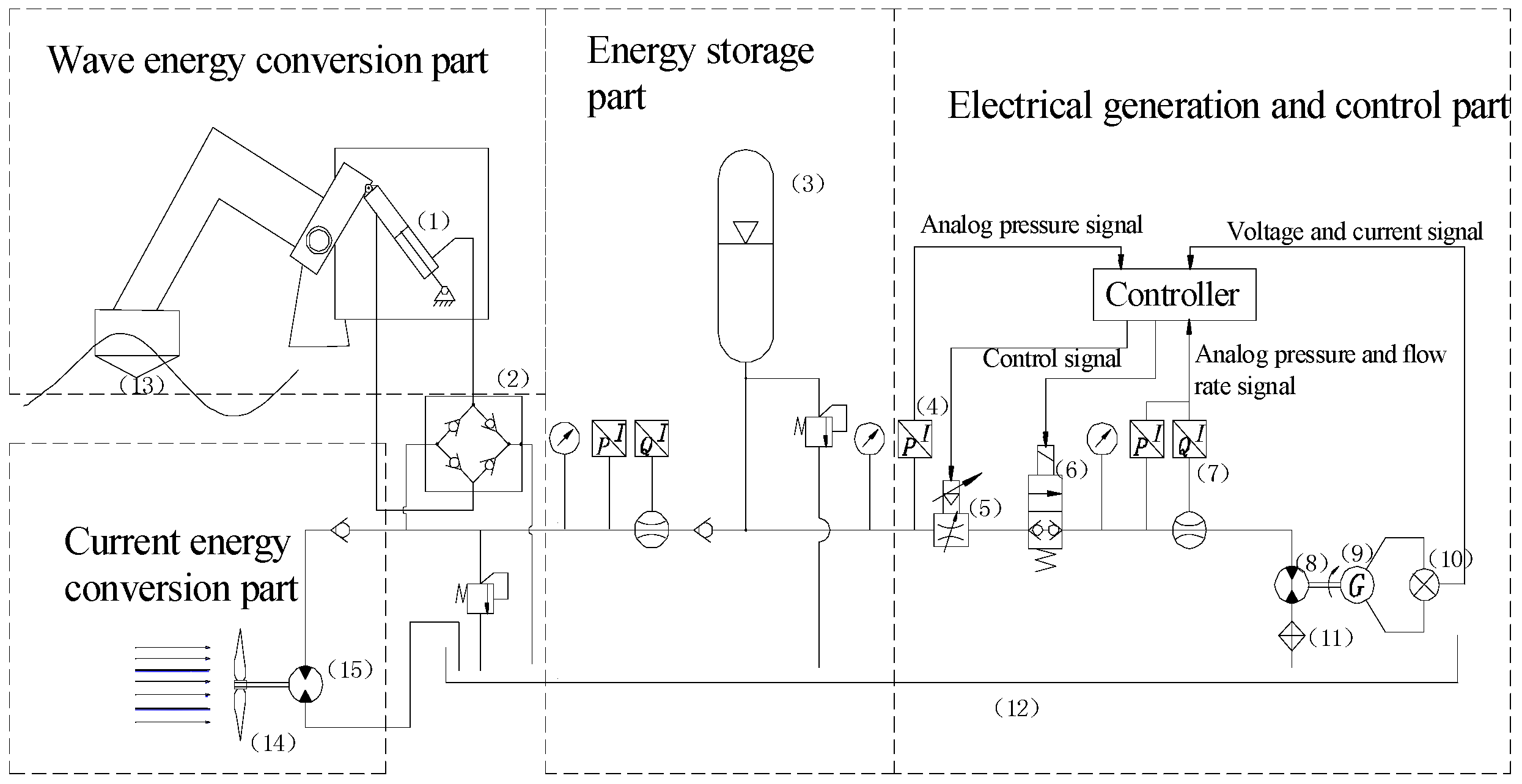
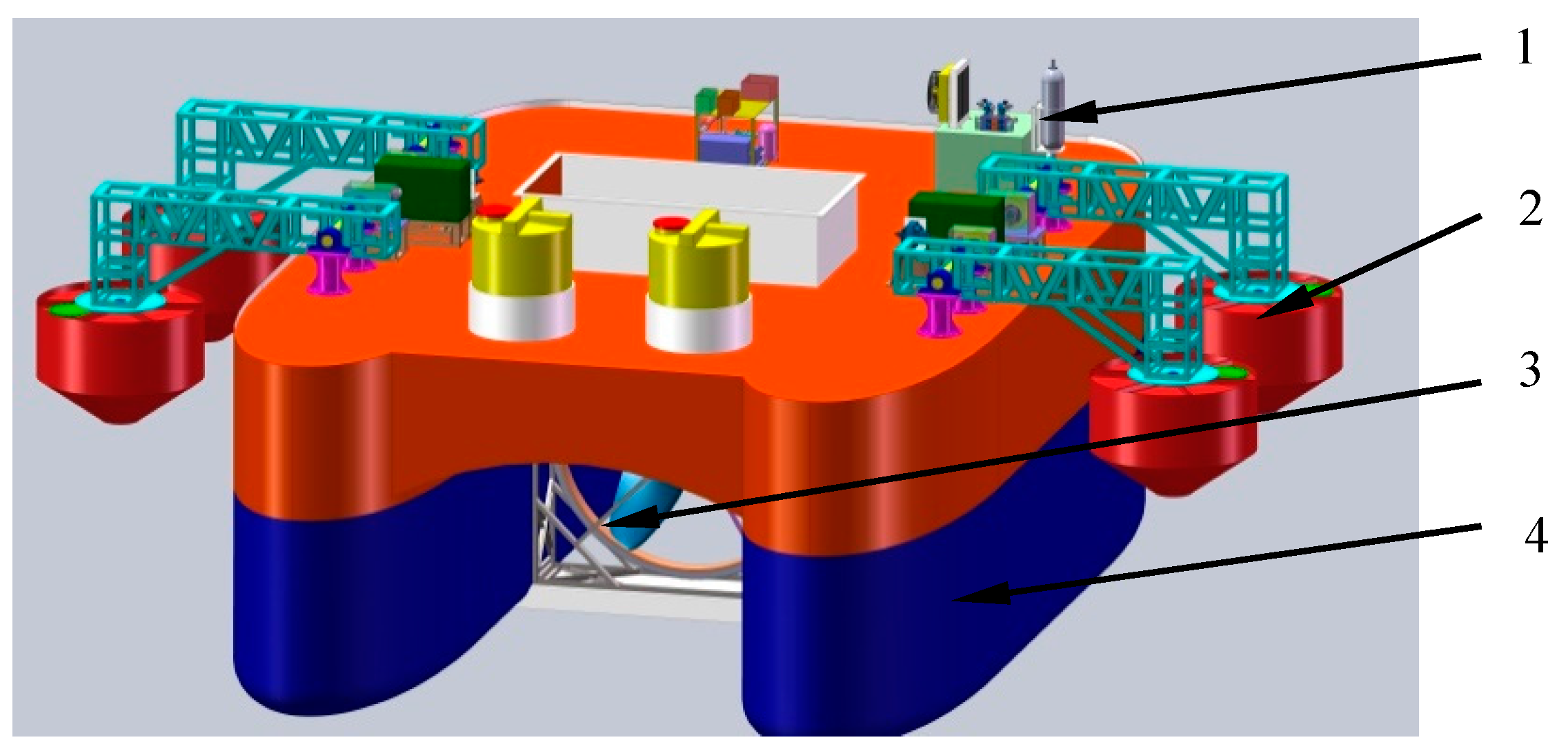
2. Design of FOECD
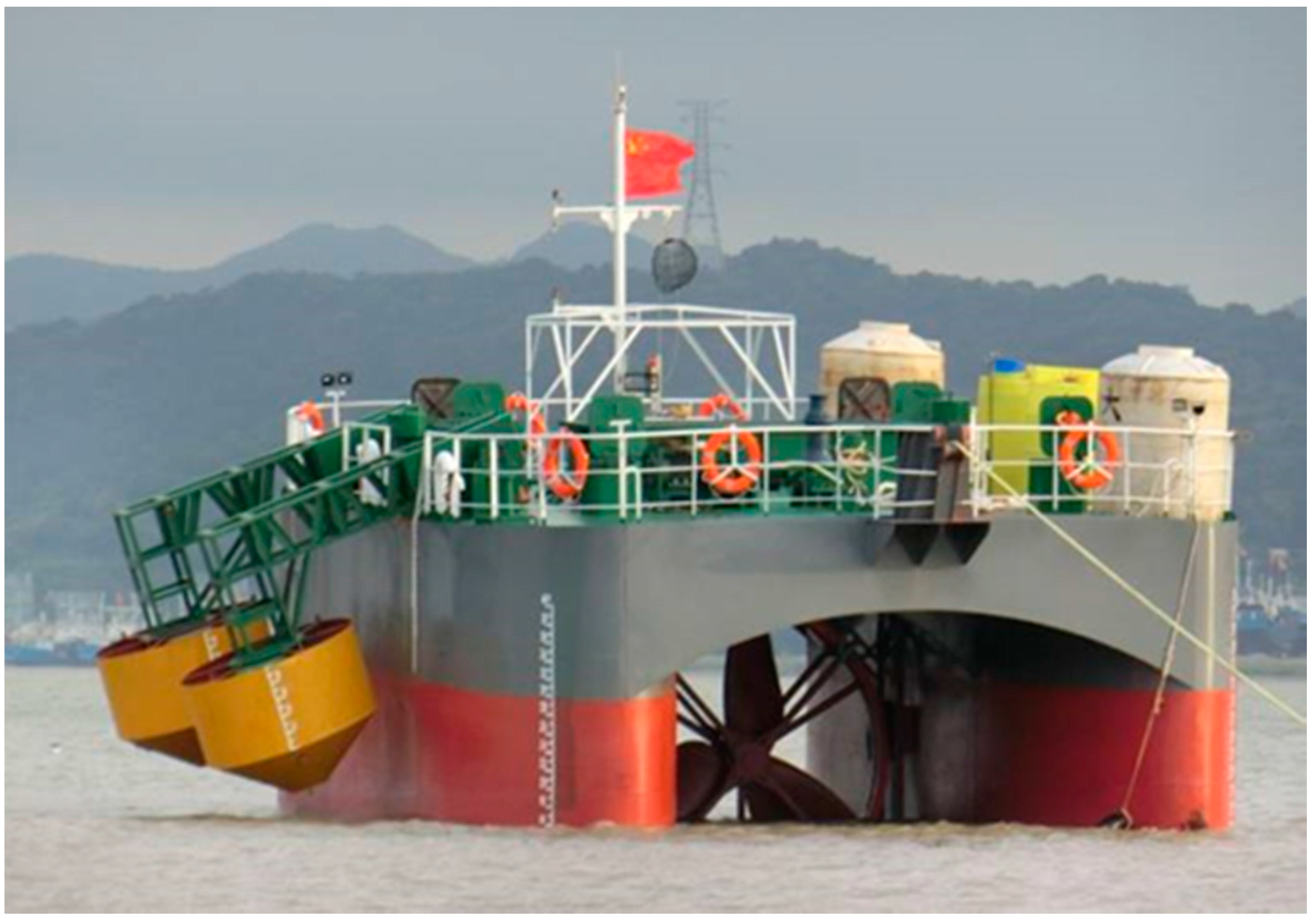
- The total length, width and height of the floating platform are 14 m, 13 m and 5.5 m, respectively. The platform body has three layers: the bottom cabins are water tanks to adjust the draught of the catamaran platform; the middle layer is the displaced oil circle and water circle; the upper layer is the control room.
- The floating platform can rise and sink with a range of 3 m by pumping water from the water tank, which is also convenient for checking oscillating buoys and current turbine blades.
- Considering the turbine blades’ need to face the direction of water flow, single-anchor mooring is adopted in the FOECD. When the current direction changes, the platform can adjust its position automatically under the current force.
- The floating platform can be towed to bay or other safe places to avoid typhoons or other severe sea conditions. It can also be conveniently dragged into port for maintenance.
- The platform can be towed to areas with abundant ocean energy considering the wave energy and current energy is changeable over a year. It can also be towed to areas near an island to supply electrical power for people who live in the island.
3. Theoretical Model of FOECD
- The fluid is an incompressible ideal fluid.
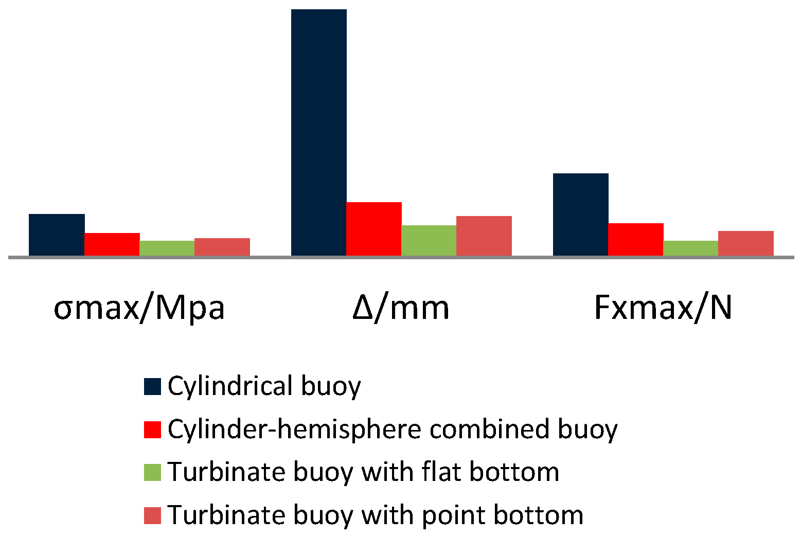
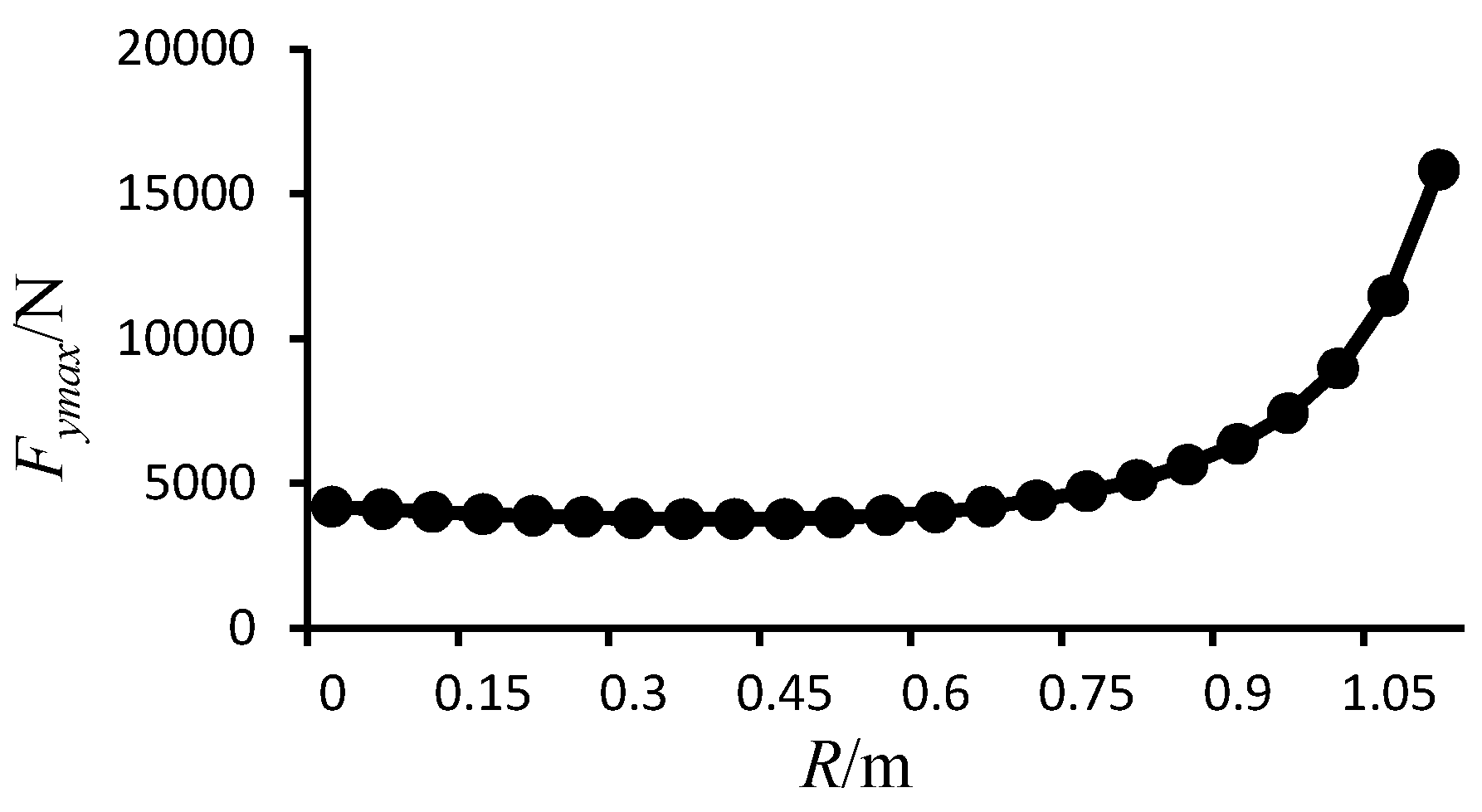
4. Proposition of Buoy Shape
5. Suitability and Power Harvesting Capability Performance Simulation for Turbinate Buoy
5.1. Suitability Analysis for Turbinate Buoy
- (1)
- The current flow is constant and the flow velocity is 2 m/s.
- (2)
- To simplify the calculation, the floating platform is fixed and the fluid direction is horizontal or vertical.
- (3)
- The body of the buoy is semi-submerged in sea water with a draught of 1.8 m.
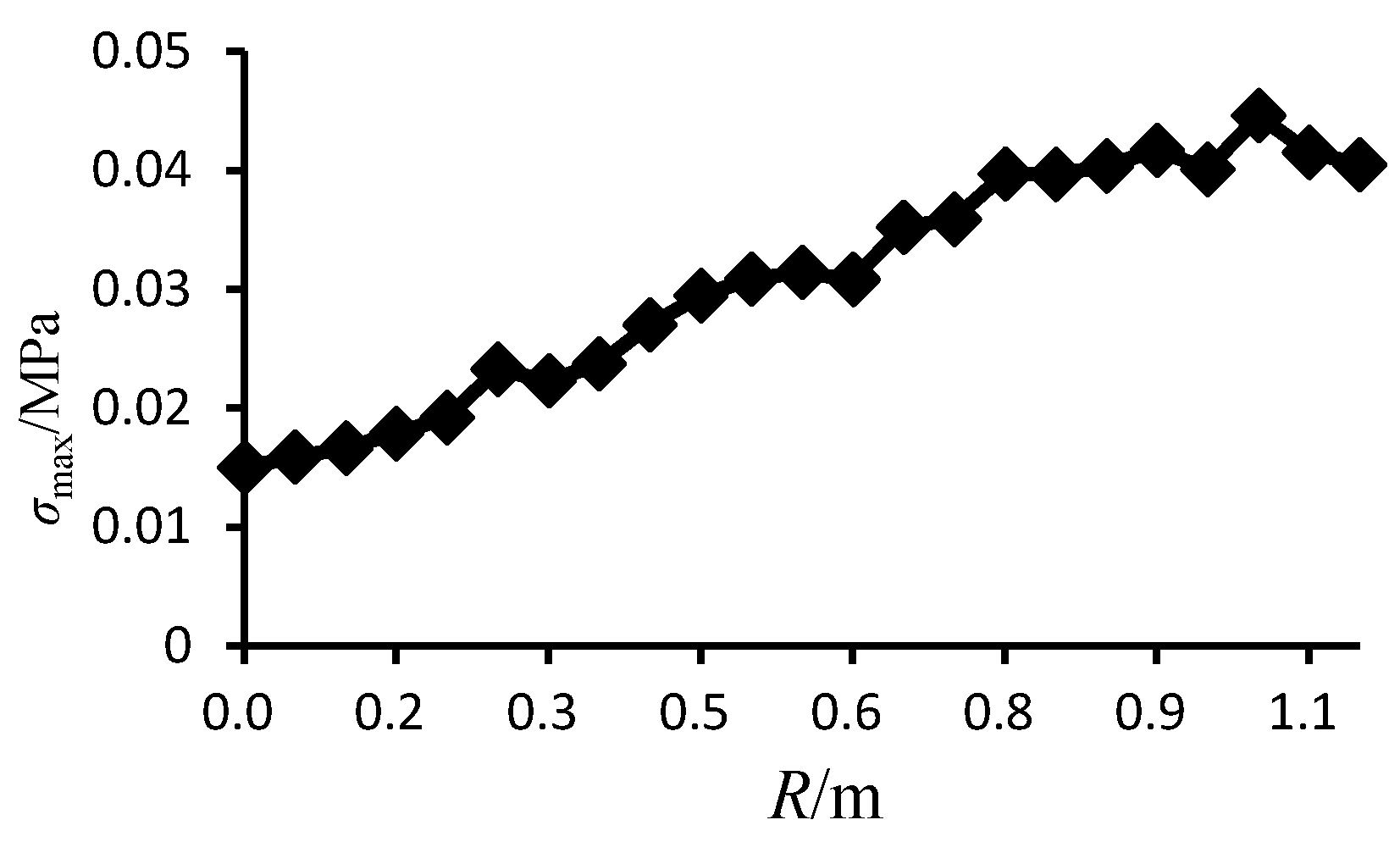
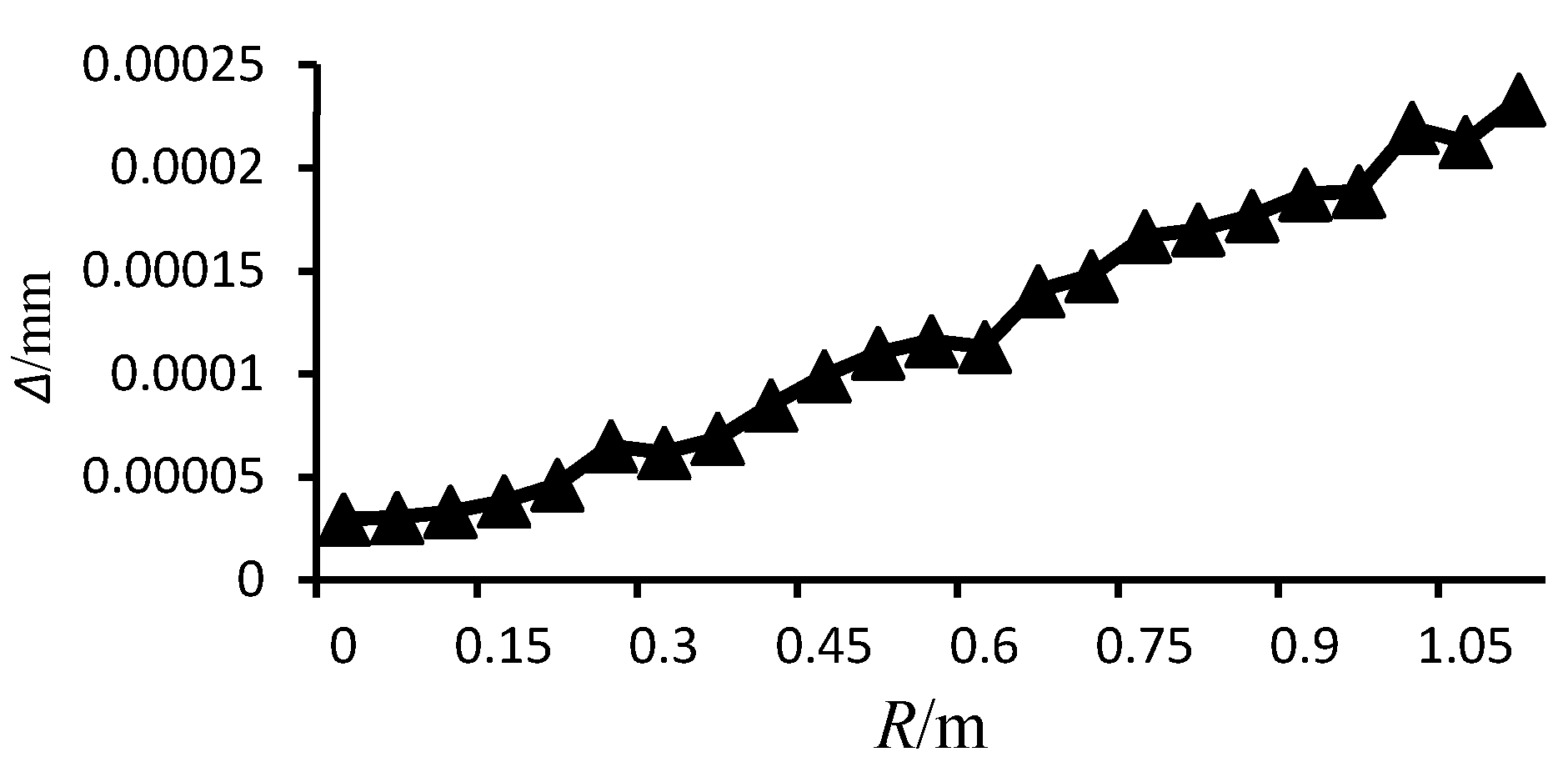
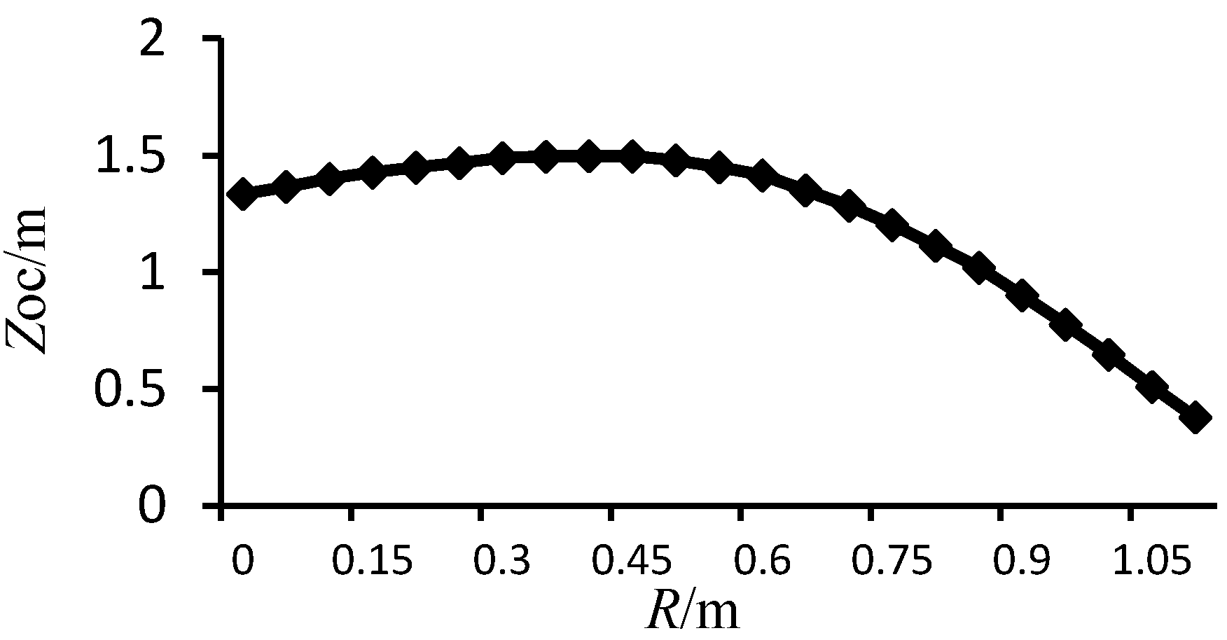
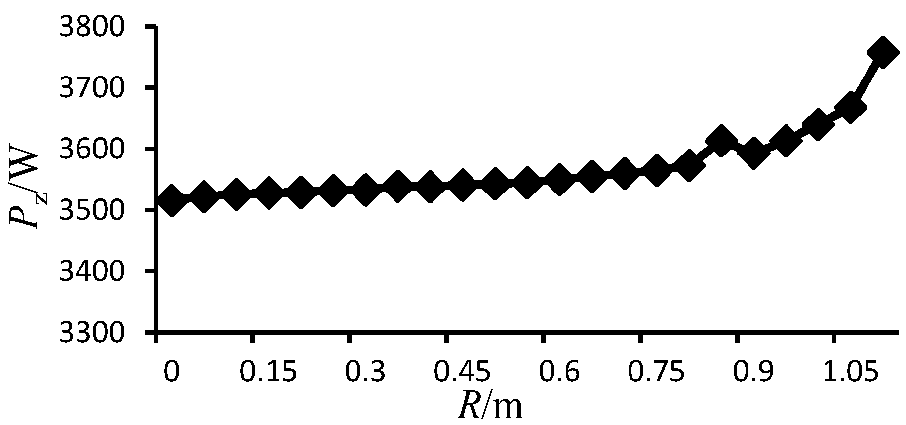
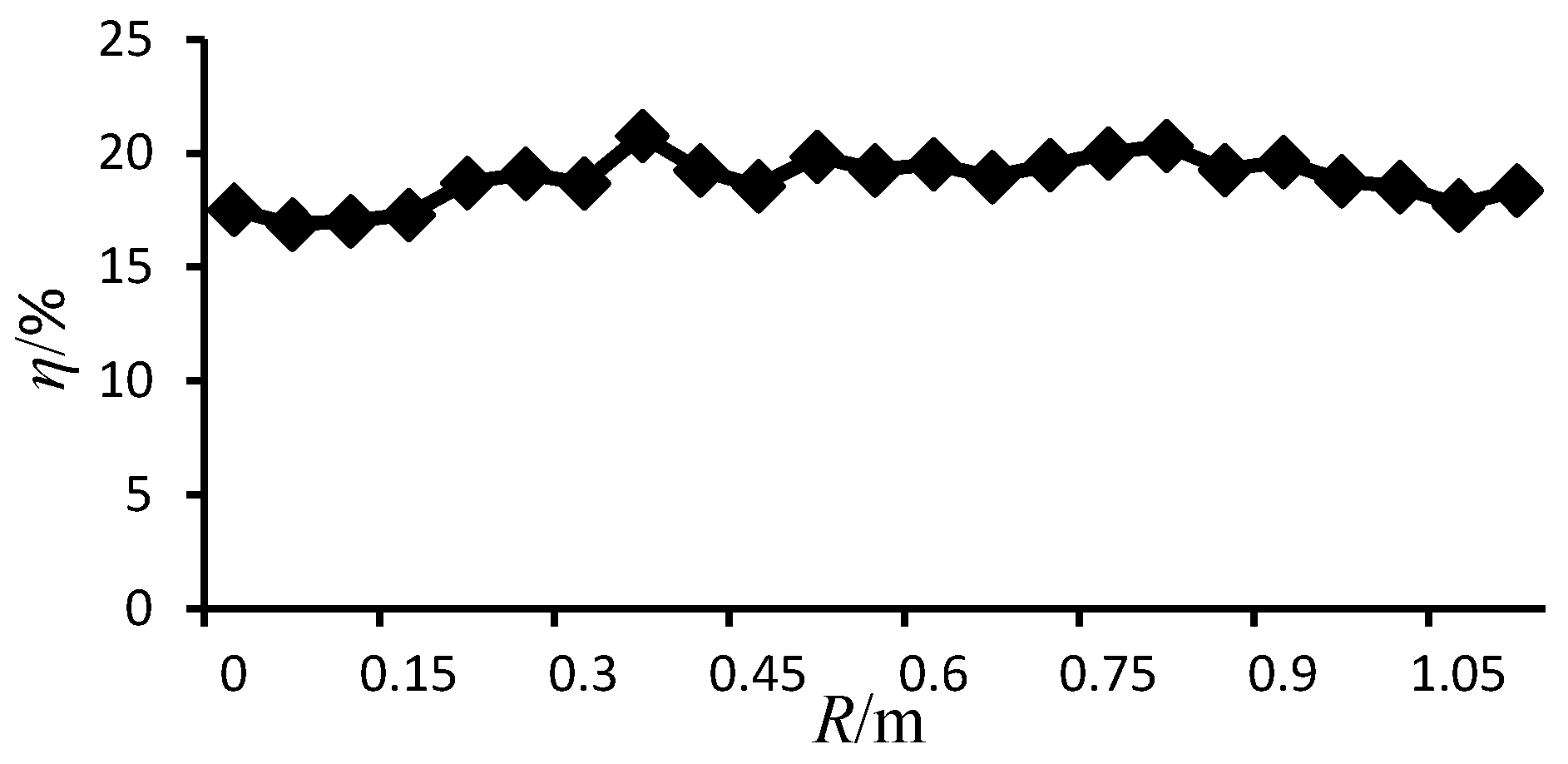
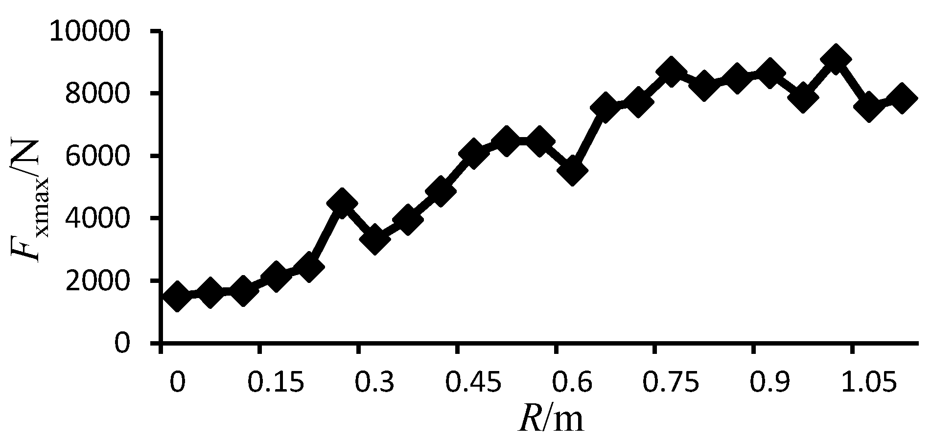
5.2. Analysis of Power Harvesting Capabilities and Efficiency
6. Establishment of FOECD
- The total length, width and height of the floating platform are 14 m, 13 m and 5.5 m, respectively.
- The rated electrical generator is 25 kW, which includes current energy generation (15 kW) and wave energy generation (10 kW).
- The wave energy capture part is composed of four turbinate buoys, each with a diameter of 2.2 m. The current capture part has three blades with a horizontal shaft which has a diameter of 4 m. The FOECD starts to work when the wave amplitude is higher than 1.2 m or the current velocity is higher than 0.8 m/s.
- To ensure safe mooring, an iron chain is used. The total length of the chain is 80 m and the anchor weight is 1.5 t. The power of the electric motor used in Capstan is 5 kW.
7. Conclusions
Acknowledgments
Author Contributions
Conflicts of Interest
Abbreviations
| FOECD | Floating Ocean Energy Conversion Device |
| PTO | Power Take Off |
| NIT | Ningbo Institute of Technology, Zhejiang University |
| SIMPLE | Semi-Implicit Method for Pressure-Linked Equations |
| N-S | Navier-Stokes |
| F-K | Froude-Krylov |
References
- Truong, D.Q.; Ahn, K.K. Wave prediction based on a modified grey model MGM(1,1) for real-time control of wave energy converters in irregular waves. Renew. Energy 2012, 43, 242–255. [Google Scholar] [CrossRef]
- Babarit, A. A database of capture width ratio of wave energy converters. Renew. Energy 2015, 80, 610–628. [Google Scholar] [CrossRef]
- Myers, L.E.; Bahaj, A.S. An experimental investigation simulating flow effects in first generation marine current energy converter arrays. Renew. Energy 2012, 37, 28–36. [Google Scholar] [CrossRef]
- Rourke, F.O.; Boyle, F.; Reynolds, A. Marine current energy devices: Current status and possible future applications in Ireland. Renew. Sustain. Energy Rev. 2010, 14, 1026–1036. [Google Scholar] [CrossRef]
- De Andres, A.; Guanche, R.; Vidal, C.; Losada, I.J. Adaptability of a generic wave energy converter to different climate conditions. Renew. Energy 2015, 78, 322–333. [Google Scholar] [CrossRef]
- Jama, M.A.; Noura, H.; Wahyudie, A.; Assi, A. Enhancing the performance of heaving wave energy converters using model-free control approach. Renew. Energy 2015, 83, 931–941. [Google Scholar] [CrossRef]
- Siegel, S.G.; Jeans, T.; McLaughlin, T.E. Deep ocean wave energy conversion using a cycloidal turbine. Appl. Ocean Res. 2011, 33, 110–119. [Google Scholar] [CrossRef]
- Zhang, D.; Li, W.; Lin, Y. Wave energy in China: Current status and perspectives. Renew. Energy 2009, 34, 2089–2092. [Google Scholar] [CrossRef]
- Wu, S.; Liu, C.; Chen, X. Offshore wave energy resource assessment in the East China Sea. Renew. Energy 2015, 76, 628–636. [Google Scholar] [CrossRef]
- You, Y.; Sheng, S.; Wu, B.; He, Y. Wave energy technology in China. Phil. Trans. R. Soc. A 2012, 370, 472–480. [Google Scholar] [CrossRef] [PubMed]
- Tiron, R.; Mallon, F.; Dias, F.; Reynaud, E.G. The challenging life of wave energy devices at sea: A few points to consider. Renew. Sustain. Energy Rev. 2015, 43, 1263–1272. [Google Scholar] [CrossRef]
- Yemm, R.; Pizer, D.; Retzler, C.; Henderson, R. Pelamis: Experience from concept to connection. Phil. Trans. R. Soc. A 2012, 370, 365–380. [Google Scholar] [CrossRef] [PubMed]
- Hearn, G.E.; Donati, E.; Mahendran, I.K. Prediction, measurement and comparison of fluid-structure interaction using mathematical and experimental results. Appl. Math. Model. 1983, 7, 41–47. [Google Scholar] [CrossRef]
- Renzi, E.; Doherty, K.; Henryb, A.; Dias, F. How does Oyster work? The simple interpretation of Oyster mathematics. Eur. J. Mech. B Fluids 2014, 47, 124–131. [Google Scholar] [CrossRef]
- Guanche, R.; Gomez, V.; Vidal, C.; Eguino, I. Numerical analysis and performance optimization of a submerged wave energy point absorber. Ocean Eng. 2013, 59, 214–230. [Google Scholar] [CrossRef]
- Mueller, M.A. Electrical generators for direct drive wave energy conversion. IEE Proc. Gener. Transm. Distrib. 2002, 149, 446–456. [Google Scholar] [CrossRef]
- Leijon, M.; Boström, C.; Danielsson, O.; Gustafsson, S.; Haikonen, K.; Langhamer, O.; Strömstedt, E.; Stålberg, M.; Sundberg, J.; Svensson, O.; et al. Wave energy from the North Sea: Experiences from the Lysekil research site. Surv. Geophys. 2008, 29, 221–224. [Google Scholar] [CrossRef]
- Wang, S.; Yuan, P.; Li, D.; Jiao, Y. An overview of ocean renewable energy in China. Renew. Sustain. Energy Rev. 2011, 15, 91–111. [Google Scholar] [CrossRef]
- Henriques, J.C.C.; Lopes, M.F.P.; Gomes, R.P.F.; Gato, L.M.C.; Falcão, A.F.O. On the annual wave energy absorption by two-body heaving WECs with latching control. Renew. Energy 2012, 45, 31–40. [Google Scholar] [CrossRef]
- McCormick, M.E. Ocean Wave Energy Conversation; Dover Publications, Inc: New York, NY, USA, 2013; pp. 42–58. [Google Scholar]
- Stansby, P.; Moreno, E.C.; Stallard, T.; Maggi, A. Three-float broad-band resonant line absorber with surge for wave energy conversion. Renew. Energy 2015, 78, 132–140. [Google Scholar] [CrossRef]
- Ramadan, A.; Mohamed, M.H.; Abdien, S.M.; Marzouk, S.Y.; El Feky, A.; El Baz, A.R. Analytical investigation and experimental validation of an inverted cup float used for wave energy conversion. Energy 2014, 70, 539–546. [Google Scholar] [CrossRef]
- Hu, Z.Z.; Causon, D.M.; Mingham, C.G.; Qian, L. Numerical simulation of floating bodies in extreme free surface waves. Nat. Hazard. Earth Syst. Sci. 2011, 11, 519–527. [Google Scholar] [CrossRef]
- Orazov, B.; O’Reilly, O.M.; Savas, O. On the dynamics of a novel ocean wave energy converter. J. Sound Vib. 2010, 329, 5058–5069. [Google Scholar] [CrossRef]
- Lin, J. Dynamic Analysis and Emulation of Float-Type Wave Power Generation Boat. Master’s Thesis, Yanshan University, Qinghuangdao, China, April 2005. [Google Scholar]
- Li, F. The Influence of Buoy Shape on Efficiency of Oscillating Buoy Wave Energy Converter. Master’s Thesis, Harbin Institute of Technology, Harbin, China, June 2011. [Google Scholar]
- Hao, N. The Structure Design and Optimization Analysis of Full Hydraulic Floating Type Wave Power Device. Master’s Thesis, Shandong University, Jinan, China, April 2012. [Google Scholar]
- Gao, R. Study on Combined Oscillating Floater Buoy Wave Energy Converter. Master’s Thesis, Ocean University of China, Qingdao, China, June 2012. [Google Scholar]


| Buoy Shape | Added Mass mω/kg | Water Plane Area Aωp/m2 |
|---|---|---|
| Cuboid buoy (semi-submersible) | KmπρLB2/4 | LB |
| Vertical cylindrical buoy (semi-submersible) | ρD3/6 | πR2 |
| Cone buoy (Full submersible) | ρD3/9 | / |
© 2016 by the authors; licensee MDPI, Basel, Switzerland. This article is an open access article distributed under the terms and conditions of the Creative Commons Attribution license ( http://creativecommons.org/licenses/by/4.0/).
Share and Cite
Song, R.; Zhang, M.; Qian, X.; Wang, X.; Dai, Y.M.; Chen, J. A Floating Ocean Energy Conversion Device and Numerical Study on Buoy Shape and Performance. J. Mar. Sci. Eng. 2016, 4, 35. https://doi.org/10.3390/jmse4020035
Song R, Zhang M, Qian X, Wang X, Dai YM, Chen J. A Floating Ocean Energy Conversion Device and Numerical Study on Buoy Shape and Performance. Journal of Marine Science and Engineering. 2016; 4(2):35. https://doi.org/10.3390/jmse4020035
Chicago/Turabian StyleSong, Ruiyin, Meiqin Zhang, Xiaohua Qian, Xiancheng Wang, Yong Ming Dai, and Junhua Chen. 2016. "A Floating Ocean Energy Conversion Device and Numerical Study on Buoy Shape and Performance" Journal of Marine Science and Engineering 4, no. 2: 35. https://doi.org/10.3390/jmse4020035
APA StyleSong, R., Zhang, M., Qian, X., Wang, X., Dai, Y. M., & Chen, J. (2016). A Floating Ocean Energy Conversion Device and Numerical Study on Buoy Shape and Performance. Journal of Marine Science and Engineering, 4(2), 35. https://doi.org/10.3390/jmse4020035