Review

Powering Underwater Robotics Sensor Networks Through Ocean Energy Harvesting and Wireless Power Transfer Methods: Systematic Review

by
Sverrir Jan Nordfjord
1,*,
Saemundur E. Thorsteinsson
2 and
Kristinn Andersen
1
1
Faculty of Electrical and Computer Engineering, University of Iceland, IS-102 Reykjavik, Iceland
2
Department of Applied Engineering, Reykjavík University, IS-102 Reykjavik, Iceland
*
Author to whom correspondence should be addressed.
J. Mar. Sci. Eng. 2025, 13(9), 1728; https://doi.org/10.3390/jmse13091728
Submission received: 24 July 2025 / Revised: 27 August 2025 / Accepted: 4 September 2025 / Published: 8 September 2025
(This article belongs to the Section Ocean Engineering)

Abstract

The global demand for innovative underwater applications is increasing, encompassing scientific research, commercial endeavors, and defense operations. A significant challenge these applications face is fulfilling the energy requirements of underwater devices. This challenge extends beyond powering individual devices to include the entire network of underwater robotic sensors. These devices have varying energy needs; some are mobile while others are stationary, and they operate under diverse environmental conditions, such as different depths, temperatures, pressures, currents, and salinity levels. This paper compares the latest state-of-the-art research on powering underwater devices, addressing the challenges and practical considerations. It examines two primary approaches: first, energy harvesting from the natural environment, and second, the use of wireless power transfer (WPT). While energy harvesting methods have been established, their effectiveness greatly depends on the specific environment in which they are deployed, making them less viable as a universal solution. On the other hand, WPT presents its challenges, particularly as its efficiency diminishes with distance. Nonetheless, it remains a promising option, and further research is essential to explore its potential, including the integration of other technologies to develop hybrid solutions that leverage multiple power sources.

1. Introduction

In recent years, we have witnessed a remarkable increase in devices that have become essential to our professional and personal lives. Many of these devices are interconnected, forming what is known as the Internet of Things (IoT). Innovative communication and power management solutions have been developed to support these devices. The next frontier is to adapt these advancements to underwater environments, paving the way for the Internet of Underwater Things (IoUT) to become a reality.
The potential of the IoUT is vast, given the scale and significance of the Earth’s oceans. Over 70% of the Earth’s surface is covered by oceans, which vary from shallow coastal areas to the deep sea. Consequently, the applications of IoUT are extensive, encompassing underwater research (such as geological studies and marine life monitoring), various commercial ventures (including mining, food production, and energy), search and rescue operations, and defense applications [1,2,3,4,5,6]. The devices used in IoUT serve different roles; some are mobile, like Autonomous Underwater Vehicles (AUVs), while others are stationary [7,8]. They operate in shallow and deep waters, but all devices require energy. Eventually, any initial energy they possess will be depleted.
In terrestrial environments, proven solutions exist for powering IoT devices, such as connecting them to existing electrical infrastructure, utilizing solar panels or small wind turbines for charging, or simply replacing batteries [9]. However, when it comes to powering IoUT devices, several limitations hinder their operational capabilities. For instance, costly expeditions may be required to swap batteries in these devices, AUVs may need to surface to recharge using solar panels [10], or they may have to return to submerged docking stations for recharging [11,12,13,14].
Numerous attempts have been documented in the literature regarding the powering of underwater devices, with varying fundamental powering technologies. Some studies have focused on different Wireless Power Transfer (WPT) methods, while others have explored ways to harness energy from natural sources. The literature also encompasses a wide range of applications; some involve sensors with limited functionality and minimal power requirements, while others include devices with extensive capabilities, such as AUVs.

1.1. Review and Methodology

This review critically examines the latest advancements in powering many different devices in underwater robotic sensor networks, focusing on two primary approaches: ocean energy harvesting (OEH) and WPT. The paper evaluates these methods’ feasibility, challenges, and potential in diverse underwater environments, providing a comparative analysis of their strengths and limitations. By combining state-of-the-art research, this review aims to identify gaps in current technologies and propose future research directions for developing efficient and sustainable power solutions for underwater applications.
We followed a structured approach for identifying, selecting, and analyzing relevant studies to ensure a comprehensive and systematic literature review of powering underwater devices. This systematic review follows a clear structure, adopting the PRISMA methodology for systematic reviews [15]. A systematic search was conducted across multiple academic databases, including IEEE Xplore, ScienceDirect, and Google Scholar. The search focused on peer-reviewed journal articles, research and review articles published in English in the last fifteen years, and non-technical papers (e.g., commentaries), and duplicates were excluded. The final search was conducted in November 2024 across the previously mentioned academic databases. This review did not have a pre-registered protocol (e.g., in PROSPERO or OSF). The absence of prior registration may introduce bias in the study selection and synthesis; however, we followed the PRISMA 2020 workflow to ensure transparency and reproducibility. The following keywords were used to refine the search:
  • Underwater energy harvesting
  • Marine energy sources
  • Underwater Wireless Power Transfer
  • Underwater sensor networks
  • Internet of Underwater Things
  • Autonomous underwater vehicle (AUV)
Several of the initial keywords gave a large number of results in the database search. Therefore, additional keywords corresponding to the chapter names and subchapters of chapters number 3 and 4 here below, were also incorporated. The previously mentioned keywords were combined using the AND operator, thereby making the search more precise. To evaluate the methodological quality of included studies, we considered factors such as clarity of study in water, replicability of methods, and reporting of quantitative results. Studies lacking clear experimental validation or reporting incomplete performance metrics were regarded as lower reliability contributions. Similarly, the risk of bias was qualitatively assessed for each study based on clarity of experimental setup, replicability of methods, and completeness of reported performance metrics. Studies lacking detailed validation or reporting incomplete results were judged at higher risk of bias, while well-documented experimental studies were considered lower risk. To minimize potential reporting bias, we searched across multiple databases and included both conference and journal papers. Nevertheless, selective reporting may remain, as some studies omitted negative results or incomplete performance data.
This review did not conduct a quantitative analysis and calculations, such as, e.g., risk ratios and mean differences. Instead, comparative evaluations of technologies were based on reported efficiency (%), power output (W), and distance (m) of operation as stated in the reviewed articles. These served as the primary effect measures and were consistently compared across studies where data were available.
The review article follows the PRISMA workflow guide for systematic reviews [15]. This process is organized into three phases: identification, screening, and inclusion (Figure 1).

1.2. Article Structure

The structure of this paper is as follows: Section 2 provides an overview of the underwater powering solutions introduced in previous studies or established in the industry to some extent. This section highlights the unique environmental factors that must be considered in underwater settings, distinguishing them from terrestrial environments. Section 3 explores several OEH methods, offering insights into their fundamental attributes, opportunities, and drawbacks when applied to an Underwater Robotic Sensor Network. Section 4 discusses various WPT options, emphasizing their essential characteristics, advantages, and limitations. Finally, Section 5 concludes with a discussion of the review and suggestions for future research directions.

2. Overview of Underwater Powering Solutions

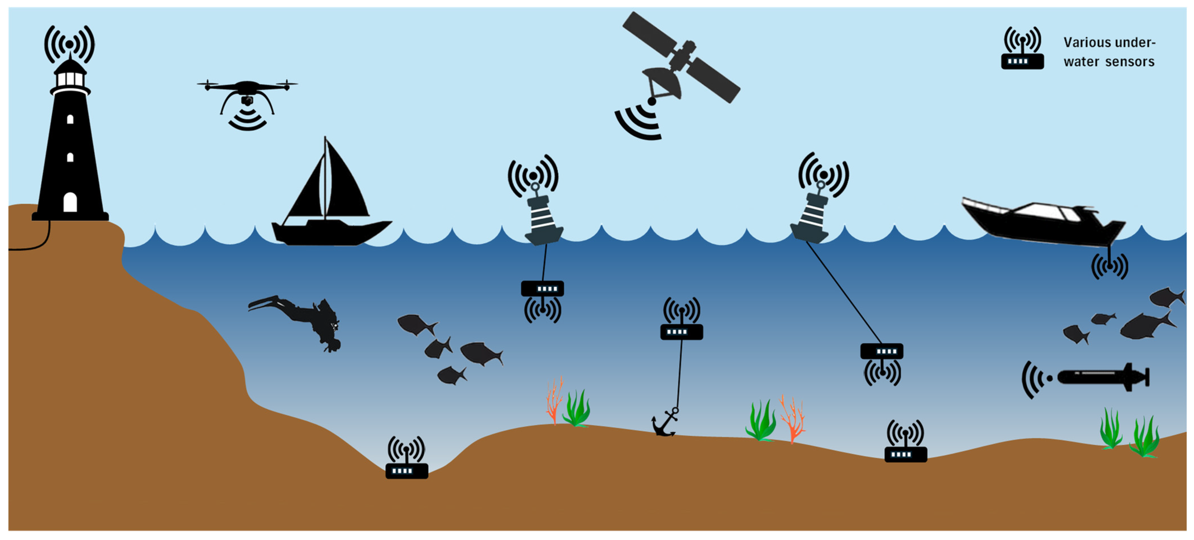
The underwater robotic sensor network comprises various devices, including AUVs, submarines, robots, and sensors. Some devices are anchored to the ocean floor, while others are mobile, both tasked with collecting underwater data. Additionally, certain devices function as relay nodes to extend communication ranges. Base stations on the water’s surface serve as gateways, facilitating data transfer from the underwater network to terrestrial networks. The nodes can be fixed to the ocean floor or floating but anchored. The mobile nodes may include Remotely Operated Vehicles (ROVs) or AUVs [16,17,18]. In some instances, existing infrastructure can be repurposed to support underwater sensor networks; for example, recent advancements have seen ocean-deployed fiber optic cables utilized as environmental sensors [19,20]. A possible architecture of an underwater robotic sensor network is illustrated in Figure 2.
This paper addresses the energy challenges encountered by underwater networks. The network includes different devices, each serving a specialized function and each with varying energy requirements. The energy demands encompass a wide range, as these devices integrate multiple sensors, wireless communication systems, actuators, and propulsion mechanisms, thereby increasing overall energy consumption. For instance, an underwater sensor device typically requires between 5 and 50 W for non-propulsion functions (such as communication, processing, and sensing), with an additional 15 to 110 W needed if the device includes propellers or other mechanical components [21]. More complex devices like AUVs and ROVs have energy requirements that range from 10 to 100 kW [11]. Conversely, some underwater devices, such as basic sensors, may operate on just a few hundred milliwatts [22,23]. It is also assumed that these underwater devices possess some form of built-in energy storage.
Powering techniques for underwater robotic sensor networks can be categorized into two main types: OEH and WPT. Subsequent sections of this article discuss additional powering solutions that fall outside these categories. Figure 3 presents an overview of several powering methods, and the structure of this paper aligns with that overview.

2.1. Energy Harvesting from Natural Phenomena

The literature has explored various options for OEH, ranging from small-scale applications powering milliwatt sensors to large-scale power plants generating megawatts. Each energy source available for harvesting is detailed in the following sections, as depicted in Figure 3.

2.2. Wireless Power Transfer

Traditionally, electrical power has been transmitted through conductive materials, such as wires. However, the research community is increasingly focusing on developing WPT and exploring innovative methods for WPT in underwater environments. The subsequent sections of this paper discuss various WPT methods that have garnered attention and demonstrated promising results.

2.3. Other Alternatives

Numerous proven techniques for power transfer have been utilized for decades, including various wired solutions [24] and manual installation of new power sources, such as battery swapping [11]. However, solutions for robotic sensor networks must be autonomous, making manual methods impractical. In many cases, wired solutions are not feasible due to distance from power infrastructure or the mobility requirements of the devices, which is why these options are not covered in this paper.
One alternative is using atomic batteries (also known as a nuclear battery or radioisotope battery), which can last the device’s operational lifetime [25,26,27], but that option does not fall within the scope of this article.
Electric field (capacitive) resonant coupling has been investigated for Wireless Power Transfer (WPT), but it is not considered suitable for underwater applications—particularly in seawater. The high conductivity of the medium leads to substantial energy losses, making power transfer inefficient. In contrast, magnetic (inductive or resonant) coupling is far more tolerant in this environment. Moreover, the small coupling capacitance achievable underwater necessitates very high plate voltages to deliver useful power, which increases insulation requirements and introduces safety concerns near instruments and personnel. Multiple reviews of underwater WPT consistently highlight these limitations and recommend magnetic approaches as the preferred solution for underwater charging [18,28,29].

2.4. Environmental Considerations

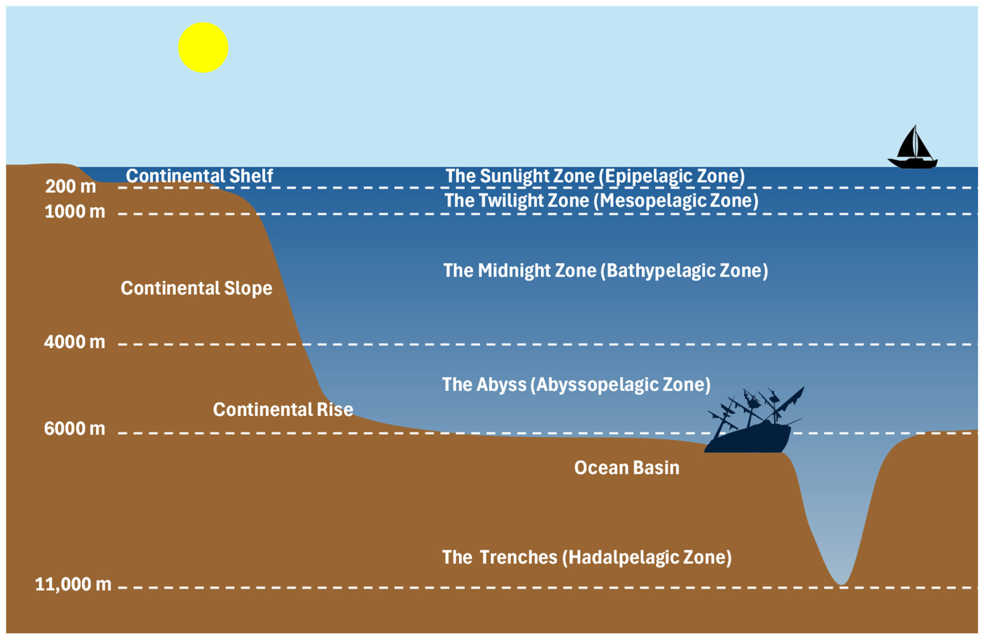
The underwater environment presents unique challenges for technology, differing significantly from terrestrial terrains. It is an oversimplification to regard the underwater environment as a uniform area; for instance, depth variations exist, as illustrated in Figure 4 [30]. Table 1 [31] details several environmental characteristics that pose additional challenges underwater.

3. Ocean Energy Harvesting

3.1. Waves

Wind blowing across the ocean’s surface generates waves, which can be harnessed and converted into electricity. Unlike tidal energy, wave energy utilizes vertical axes to capture the energy from the rising and falling waves. The size of the waves is influenced by wind speed and duration. Waves tend to travel in a more streamlined way than wind, and their more consistent direction allows them to generate greater power. Similar to how a ship at sea experiences six primary types of motion, other devices can also experience these same motions (see Figure 5).
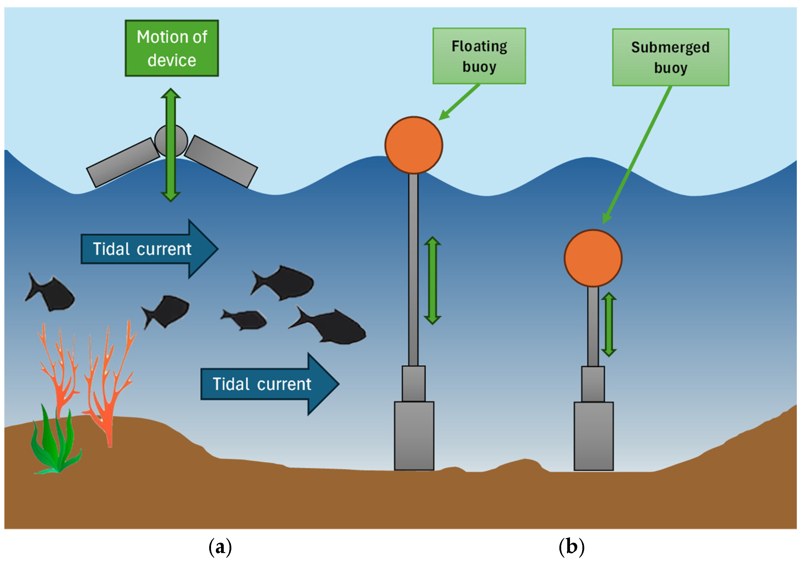
Some researchers have proposed technologies that utilize wave-induced pitching, heaving, or surging to harvest energy from ocean waves. Energy can be extracted directly from surface waves or by harnessing the pressure fluctuations beneath them. Various technical devices have been developed for energy harvesting, including Oscillating Water Columns, Oscillating Body Converters, Overtopping Converters, Wave-Activated Bodies, and Point Absorbers, among others [34,35,36]. Examples of these devices are illustrated in Figure 6.

3.2. Solar Energy

Some AUVs are equipped with solar cells that charge their batteries. In many cases, these AUVs surface to allow the solar cells to absorb energy from the sun. Examples of such applications can be found in the references [36,37].
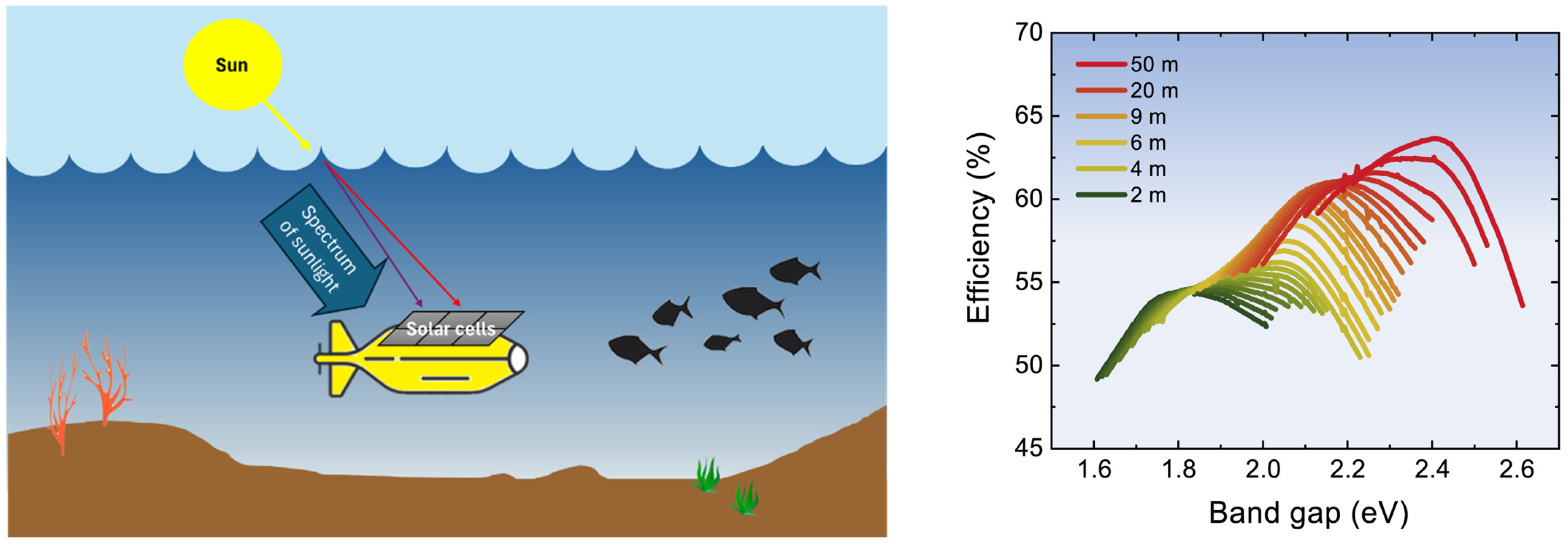
Using solar power beneath the ocean’s surface may seem counterintuitive, as water scatters and absorbs visible light. However, research suggests this approach can be feasible when using appropriate semiconductor materials in the solar cells and operating at specific depths [38]. Certain wavelengths of solar light penetrate deeper into the ocean, making it essential to select semiconductor materials with the right band gap to convert these specific wavelengths into electricity. While this review does not cover selecting the most suitable semiconductor materials, numerous options are available, each varying in efficiency, band gap, film quality, and cost. For instance, hydrogenated amorphous silicon (a-Si: H) can be tuned to a band gap between 1.55 and 2.1 eV, making it a strong candidate for use at shallower depths. Additionally, semiconductors such as CuO2 and ZnTe have band gaps of 2.17 and 2.25 eV, respectively, which make them suitable for underwater solar energy harvesting at greater depths [39,40,41]. Other semiconductor options include cadmium zinc telluride (CZT), copper zinc antimony sulfide (CZAS), AlGaAs, InGaP, and GaAsP [41,42,43,44,45].
The relationship between water depth and efficiency for different band gaps is illustrated in Figure 7.
Research has demonstrated that in some of the clearest natural waters, solar cells can effectively harvest solar energy at depths up to 50 m below sea level, achieving efficiencies exceeding 63%. Furthermore, operating these solar cells in colder waters can enhance their efficiency due to the improved performance of semiconductor materials at lower temperatures [38,46]. This combination of suitable semiconductor materials and optimal operating conditions makes underwater solar power a viable option in specific environments, particularly where water clarity allows solar cells to be positioned at depths that still permit adequate light penetration.

3.3. Kinetic Energy of Water (Tidal Currents and Flows)

Ocean currents represent a significant source of energy, consisting of both horizontal and vertical components. They are analogous to wind in the atmosphere, despite water being approximately 850 times denser than air [47].
One promising source of energy harvesting in the ocean is tidal energy. The energy derived from tides relies on predictable and consistent vertical water movements. These predictable vertical motions can be converted into kinetic energy for electricity generation. Tidal energy is primarily categorized into tidal range and tidal current, also known as tidal barrages and tidal current energy converters [47,48]. Each form requires distinct methods for energy harvesting.
The tidal range utilizes dams and reservoirs to capitalize on sea-level cyclic rise and fall, extracting energy from these fluctuations, much like hydropower generation, thus less suitable for smaller-scale and mobile IoUT applications. The second method involves harnessing local tidal currents, akin to wind power or the use of tidal kites [34]. This technology employs tidal current energy converters, such as tidal turbines, to capture the kinetic energy of moving water [23,34]. Over the past few years, various types of tidal turbines have been developed, with capacities ranging from hundreds of megawatts to just a few watts [34,47,49]. Three examples of these tidal current turbines are illustrated in Figure 8.

3.4. Temperature Variations

Generating electricity from the temperature differences in the ocean primarily relies on a process known as Ocean Thermal Energy Conversion (OTEC). OTEC utilizes the temperature gradient between the warm surface water and significantly colder deep water.
Warm seawater, typically ranging from 25 °C to 30 °C, is drawn from the ocean’s surface and serves as the heat source for the OTEC system. This warm surface water flows through a heat exchanger, transferring its heat to a working fluid with a low boiling point, such as ammonia or a refrigerant. As a result, the working fluid vaporizes. The expanding vapor drives a turbine connected to a generator, thereby producing electricity. Subsequently, the vaporized working fluid passes through another heat exchanger, where the cold deep seawater, usually around 5 °C, condenses the vapor back into a liquid. The condensed working fluid is then recirculated to the initial heat exchanger to repeat the cycle [23,34,36], as illustrated in Figure 9.
Adapting OTEC principles to a smaller scale, such as for robotic sensor networks, including AUVs, presents challenges and opportunities. As the AUV ascends to shallower depths, it collects warm water. A compact heat exchanger attached to the AUV would transfer heat from the warm surface water to a low-boiling point working fluid, causing it to vaporize and drive a small turbine or microgenerator to produce electricity. This electricity could then be stored in the AUV’s batteries or used directly to power its systems. The AUV would then descend to deeper, colder waters, where another heat exchanger would enable the cold water to condense the vaporized working fluid back into a liquid. The liquid working fluid would be pumped back to the initial heat exchanger, ready to be vaporized again, thus completing the cycle [23,50,51,52].
This energy harvesting method can be particularly beneficial in regions with significant temperature gradients, providing a continuous power supply that enhances the AUV’s efficiency and mission capabilities. However, the AUV must operate within a depth range that ensures sufficient temperature gradients, which may limit its operational flexibility. The AUV must frequently transition between warm and cold water layers, potentially impacting mission planning and energy consumption.

3.5. Fuel Cells

A fuel cell is an electrochemical device that produces electrical energy through the chemical reaction between fuel and oxygen. An alternative to traditional fuel cells is the semi-fuel cell, which generates electricity by oxidizing a metal in the presence of oxygen. In semi-fuel cells, seawater serves as the electrolyte, utilizing a metal anode and an air cathode, achieving specific energy outputs of up to 500 Wh/kg [11].
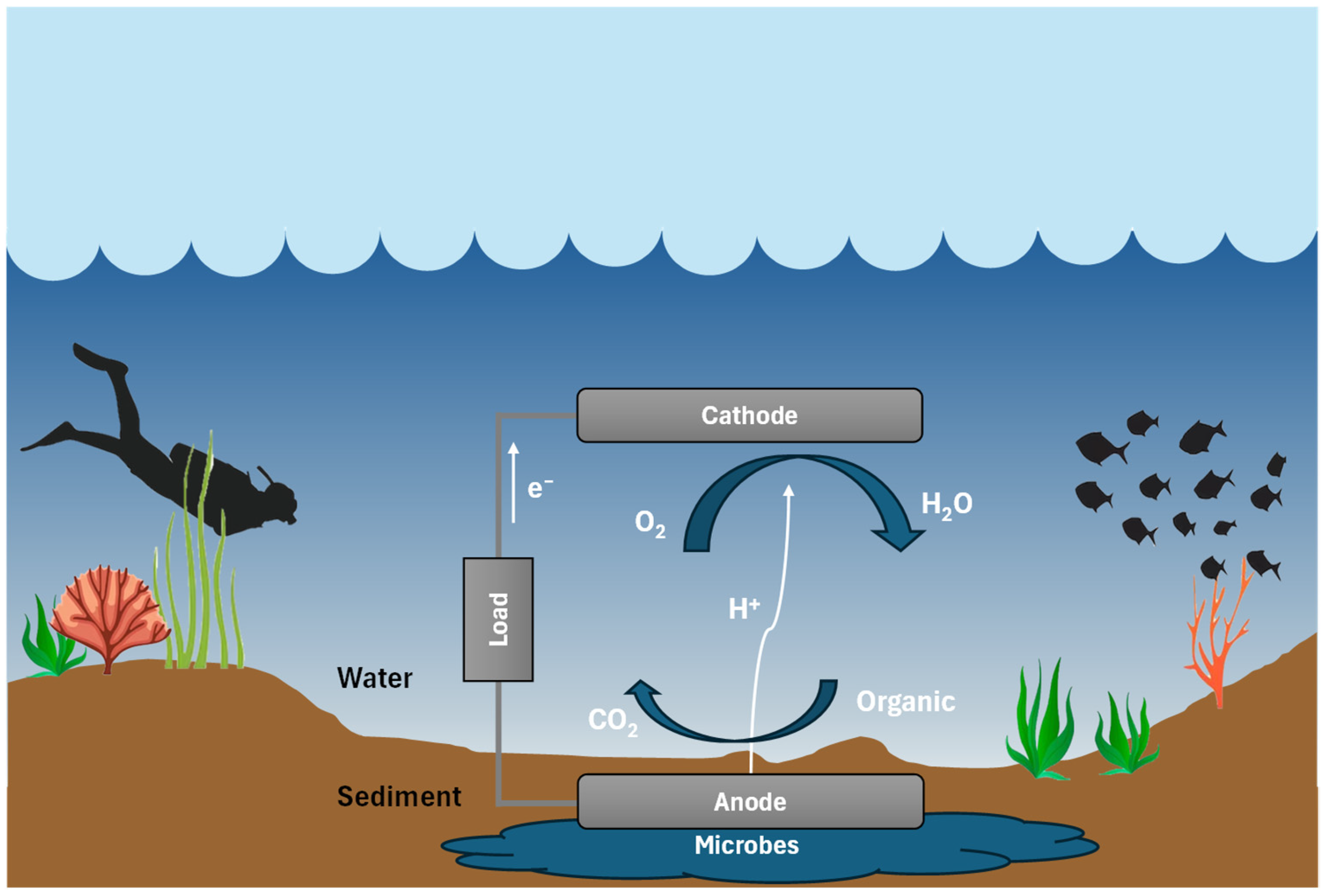
Microbial fuel cells (MFCs) harness the metabolic activities of microorganisms in water as a renewable energy source, converting this energy into electricity to power IoUT systems [53]. Like batteries, MFCs consist of two electrodes: an anode and a cathode. The anode is placed in sediment where oxygen is absent, while the cathode is submerged in water above the sediment. The microorganisms in the sediment generate electrons by breaking down organic matter through an oxidation process. These electrons are transferred to the anode and flow toward the cathode, creating a current that powers the load connected to the MFC [21,53]. A schematic diagram of an MFC is illustrated in Figure 10.
The research indicates that most MFCs are reported to generate only a few microwatts of power [21,54,55]. One implementation described a power management system (PMS) that enables an MFC to power a wireless sensor requiring 2.5 W [56]. The energy produced by the microbial fuel cell is stored in capacitors and periodically transmitted to the sensor in bursts, allowing the capacitors sufficient time to recharge between transmissions. Due to low power output from the bacterial oxidation process, it takes several hours to fully charge the capacitors, with approximately 27 min required between each transmission [56]. This significantly limits the effectiveness of the solution.

3.6. Piezoelectric Materials

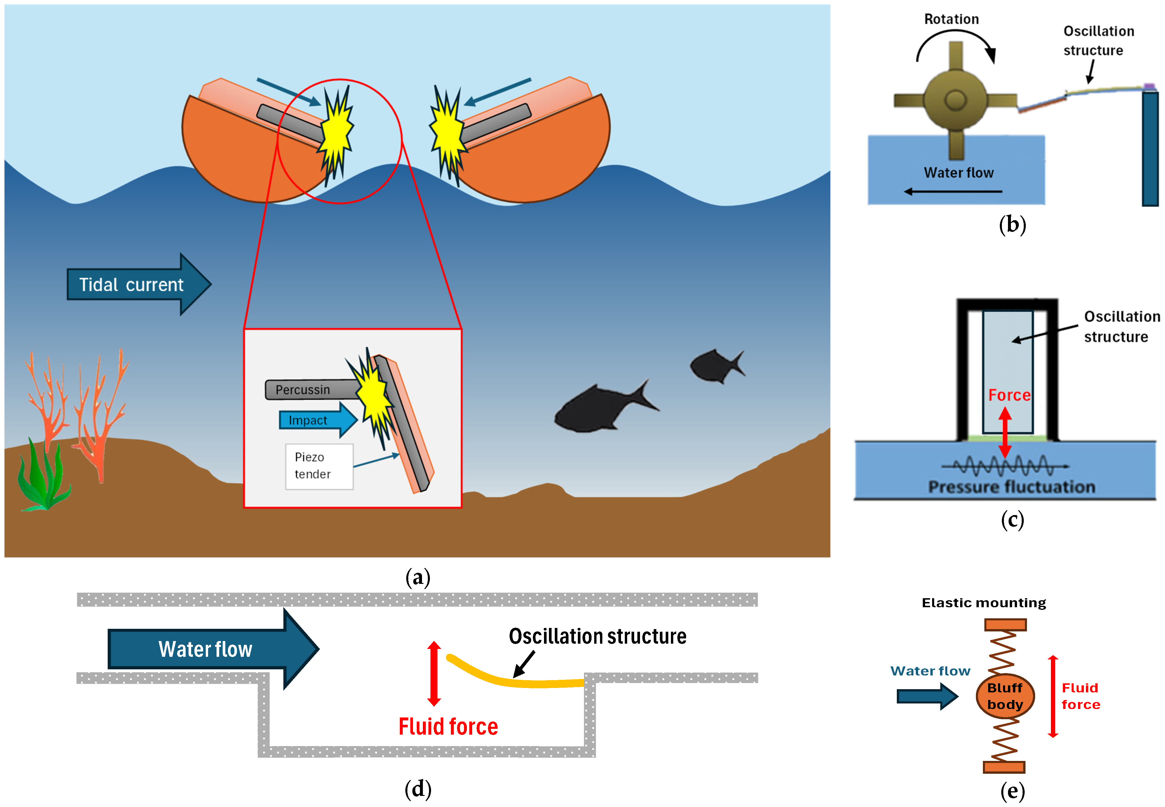
Numerous researchers have explored various aspects of utilizing piezoelectric methods for energy harvesting from water flow [57]. The range of topics is extensive and to highlight a few, key considerations include identifying the most suitable materials (such as PZT—lead zirconate titanate, MFC—macro fiber composite, PVDF—polyvinylidene fluoride, and ZnO—zinc oxide), as well as determining the optimal structural design for both the piezoelectric materials and the water flow system. This includes factors like vortex-induced vibrations, galloping, fluid forces resulting from bluff body motion, wake-induced vibrations, turbulent flow, turbulence-induced vibrations, cavity flow-induced vibrations, pressure fluctuations, and wave motions. Various structures designed for piezoelectric energy harvesting are illustrated in Figure 11. The topic is diverse and encompasses many facets [23,57].
While several piezoelectric energy harvesting methods have demonstrated the ability to generate power from water flow, recent research indicates that a significant gap remains between the power harvested and the power required for most underwater applications [57].

3.7. Summary of Ocean Energy Harvesting Methods

The various OEH methods outlined above present both advantages and disadvantages. A significant drawback is the increased complexity of installing and maintaining devices in oceanic environments compared to onshore settings. Additionally, these solutions may have potential environmental impacts. The different pros and cons of each method are summarized in Table 2.
Each technique has its strengths and limitations. Wave and tidal/current energy have a high potential for acceptable power generation. Solar energy and OTEC are effective in certain climates but are geographically constrained. Fuel cells and piezoelectric materials are ideal for powering small devices but are not suitable for large-scale energy generation in their current forms.
The different energy harvesting methods listed above have been reported in the literature to various degrees and with other aspects and possible usage. Table 3 summarizes the main findings and strengths of the different articles and their limitations. Table 4 also provides an overview of the OEH techniques, indicating the expected power level from the applied technique as reported in the literature.

4. Wireless Power Transfer (WPT)

4.1. Inductive Coupling

Inductive coupling is a technique for transferring energy between two circuits or devices through electromagnetic induction. This process is based on mutual inductance, where a changing magnetic field generated by one coil induces a voltage in a nearby coil. When an electric current flows through the primary coil, it creates a magnetic field around it. If a second coil, known as the secondary coil, is positioned within this magnetic field, the fluctuating magnetic field induces an electric current in the secondary coil. This phenomenon is referred to as electromagnetic induction.
A schematic diagram illustrating inductive coupling is presented in Figure 12, which depicts the contactless power transmission used in a charging system.
The primary coil is connected to an alternating current (AC) source. The green lines represent a time-varying magnetic field emanating from the primary coil and reaching the secondary coil. The induced voltage in the secondary coil generates an electrical current that flows through the coil and powers the load.
The efficiency of energy transfer between the two coils is determined by their mutual inductance, which indicates how effectively the magnetic field of the primary coil (the transmitter) induces a voltage in the secondary coil (the receiver). Several factors influence mutual inductance, including the number of turns in the coils, the distance separating them, the frequency of the current, and the surrounding materials between the coils.
Inductive coupling is a well-established technology for wireless charging in terrestrial applications, such as smartphones [58] and electric vehicles (EVs) [59]. Research has also explored its effectiveness for underwater applications [11,12,60,61].
One significant advantage of this technology is its relatively high efficiency, reaching around 90% in optimal conditions [11]. Additionally, the conducting materials can be housed in separate devices, keeping them dry in underwater environments. However, this method of power transfer is limited to relatively short distances, typically just over a centimeter [8,11,21,60,62,63,64,65,66], beyond which efficiency diminishes. A comparison of various inductive coupling solutions that have been tested is presented in Table 5, highlighting their limited range and efficiency.
Consequently, this solution is most beneficial when at least one of the devices is mobile (either the energy transmitter or receiver). If both devices are stationary and only a few centimeters apart, they could be connected with a short cable. Nonetheless, WPT remains practical for numerous applications, having been tested at depths of up to 2000 m below sea level [31].
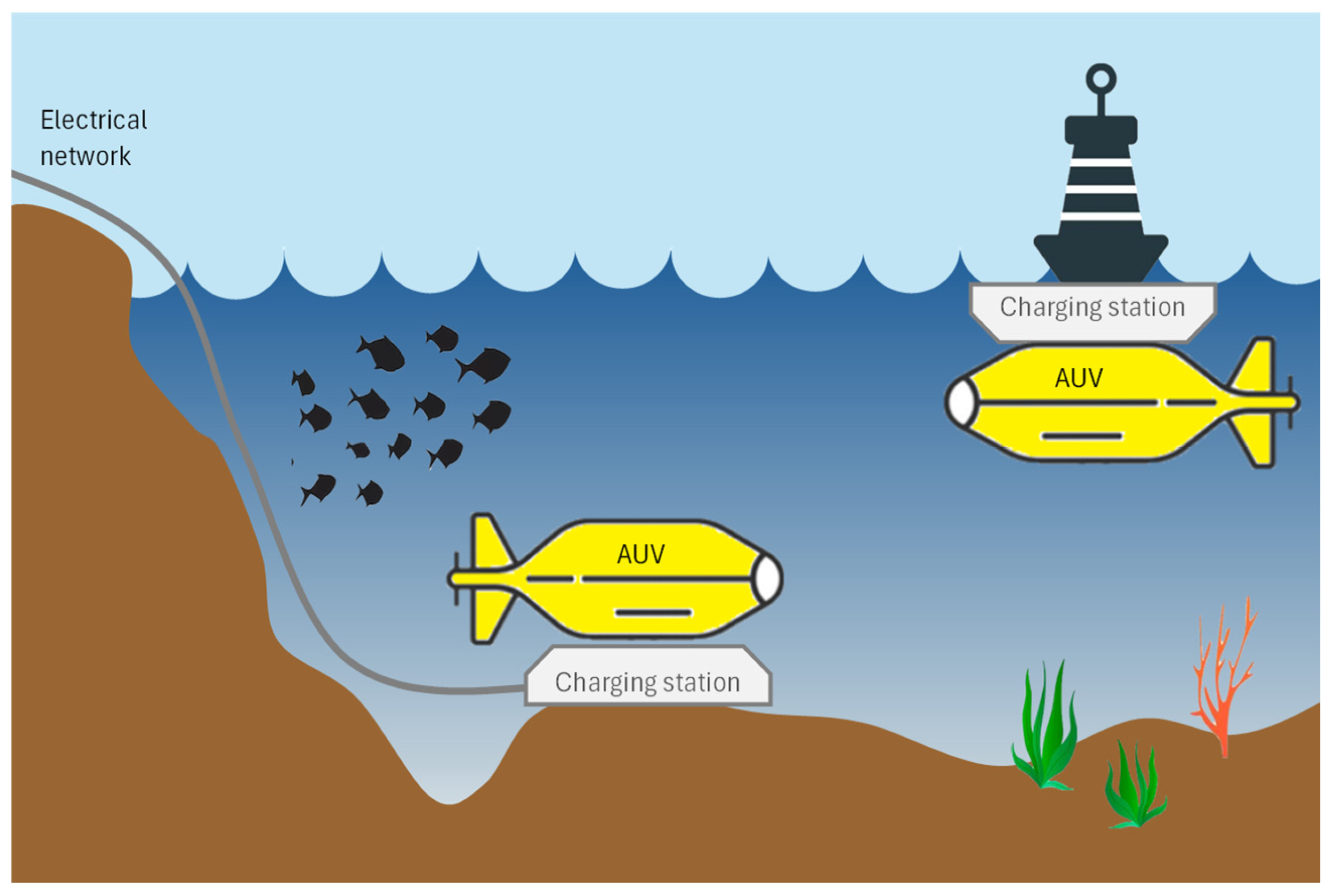
Table 5 compares several tested inductive coupling solutions, showcasing their relatively short ranges and efficiencies. Two configurations for charging stations designed for AUVs are illustrated in Figure 13.
One example depicts a charging station on the ocean floor, connected to an underwater cable that links to the onshore electrical power grid. In this scenario, the AUV can rest on the charging station and be wirelessly charged through inductive coupling. The other example shows a charging station positioned beneath a buoy (such as one equipped with solar panels), allowing the AUV to float underneath for WPT.

4.2. Magnetic Resonance

In the context of wireless charging for electrical devices, “Magnetic Resonance” is often referred to as “Resonant Inductive Coupling”. This technique is a specific variant of the inductive coupling method discussed in the previous section. Magnetic Resonance in wireless charging involves generating a magnetic field that oscillates at a precise frequency. Both the transmitter (charging station) and the receiver (device) are tuned to this frequency, facilitating a more efficient transfer of energy.
The primary distinction between this method and traditional inductive coupling is that both the transmitter coil in the charging station and the receiver coil in the device are designed to resonate at the same frequency. This is typically accomplished using coils and capacitors precisely tuned to the resonance frequency (see Figure 14).
The Magnetic Resonance method allows for efficient energy transfer between a charging station and a device without the need for direct electrical connections. It is commonly used for charging various portable electronic devices [8,11,65].
While this method achieves an efficiency comparable to that of inductive coupling, it operates effectively over slightly longer distances between the two devices (the gap between the primary and secondary coils), typically a few centimeters [31]. Table 6 provides examples of efficiency ratings and corresponding gap distances.
In addition to enabling longer charging distances, Magnetic Resonance accommodates a higher degree of misalignment between the two coils (the charging station and the device) [11]. Various alternatives to this solution have been explored in the literature under terrestrial conditions, and some underwater [73,74]. There are also examples of where additional coils have been introduced to enhance power transfer and coil shape and dimensions have been explored. These innovations aim to extend the range of wireless connections, improve efficiency, and adjust for misalignment [75]. Magnetic resonance continues to be an active area of research aimed at improving efficiency and robustness in diverse operational scenarios.

4.3. Ultrasonic/Acoustic Wireless Power Transfer

Ultrasonic or Acoustic WPT is a technique that employs sound waves, particularly ultrasonic frequencies (above 20 kHz, beyond the range of human hearing), to transmit energy wirelessly over a distance. This emerging technology converts sound energy, typically outside the audible range, into electrical energy to power or charge devices [76].
In this method, a transmitter consists of a power source and a piezoelectric transducer (PZT), which converts electrical energy into ultrasonic waves. This process is similar to how a speaker transforms electrical signals into sound waves but operates at much higher frequencies. The ultrasonic waves travel through a medium such as water (though they can also propagate through air or solid materials) to reach the receiver. These waves carry energy in the form of mechanical vibrations. At the receiver, another ultrasonic PZT captures the sound waves and converts them back into electrical energy (AC) when subjected to mechanical stress from the ultrasonic waves.
This transducer is connected to a full-wave rectifier, an electronic circuit that converts AC into DC (Direct Current). The DC output from the rectifier can then be used to directly power electronic devices, charge batteries, or be stored in capacitors for later use [21,77].
Piezoelectric materials are particularly suitable for this application, as they generate electricity when subjected to mechanical pressure or vibrations. This method of WPT is illustrated in Figure 15.
The same principle applies to both acoustic and ultrasonic waves for WPT, as both are forms of sound waves. The primary distinction between them lies in their frequency ranges: acoustic waves refer to sounds within the human hearing range (typically between 20 Hz and 20 kHz), while ultrasonic waves have frequencies exceeding the upper limit of human hearing (above 20 kHz).
One of the key advantages of using ultrasonic or acoustic waves for WPT is their lower attenuation in water, allowing them to cover longer distances than magnetic induction methods such as inductive coupling or magnetic resonance. This capability makes it feasible for chargers and powered devices to be placed further apart, not limited to just a few centimeters but operating at distances one or two orders of magnitude greater. Consequently, the research community is increasingly interested in this method for WPT in extreme environments, such as underwater or underground [78]. However, it is worth noting that the efficiency of this solution is relatively low, typically less than 5% when operating over distances greater than one meter [12,21]. Table 7 presents the efficiencies and gap distances achieved with ultrasonic/acoustic WPT.

4.4. Optical Wireless Power Transfer

Optical Wireless Power Transfer (OWPT) involves converting electrical power into light or a laser beam. The light is directed towards a receiving device employing a photosensitive panel or photovoltaic (PV) cell to convert the laser beam to electrical power. This power can then be utilized by a device or stored in a battery. Figure 16 illustrates this method of WPT.
While this power transmission technique offers several advantages, it also presents significant challenges. One notable benefit of optical power transmission is its compact size, making it ideal for applications with limited space. Additionally, laser beams can transmit power over considerable distances. Unlike radio frequency (RF) methods, laser-based systems do not generate electromagnetic interference (EMI), which can disrupt other electronic and communication systems [76].
However, effective power transmission necessitates a clear line of sight between the transmitter and the receiver. Obstacles such as murky water or physical barriers can obstruct the laser beam, interrupting energy transmission. Precise alignment between the laser source and the photosensitive panel is essential, and this alignment becomes particularly challenging in underwater environments due to factors like water currents and the movement of devices [18,50].
Optical power transmission can also be influenced by ambient light and other environmental factors, which may interfere with the laser beam and diminish efficiency. The clarity of the water is crucial for underwater applications, as murky or unclear water can significantly attenuate the laser beam, reducing the effectiveness of power transmission. Additionally, different wavelengths of light exhibit varying levels of attenuation; for example, the wavelengths 405 nm (blue), 531 nm (green), and 660 nm (red) have different transmission distances and efficiencies in various types of water [82]. Although there is a limited number of tested examples in the literature, a comparison of a few instances is presented in Table 8.
The process of converting electrical power to laser energy and back again can result in significant energy losses, making the overall efficiency of this method lower than that of other techniques. Many researchers view laser-based Wireless Power Transmission (WPT) as impractical due to its inherent inefficiencies, safety concerns (high-power lasers pose risks to humans and marine life), and vulnerability to environmental interference. Studies and analyses have raised questions about the feasibility of the widespread adoption of laser-based WPT [11,31,86].
While optical power transmission using laser beams shows promise for certain applications, its practical implementation is hindered by substantial challenges, including the need for a clear line of sight, precise alignment, environmental interference, and safety concerns. These factors must be carefully considered when assessing the viability of this technology for specific use cases.

4.5. Summary of Wireless Power Transmission Methods

The WPT methods discussed in the preceding subsections exhibit distinct advantages and limitations, just as the OEH methods do. The reviewed WPT methods have been investigated in the literature to varying extents, with different performance aspects and potential applications emphasized. Table 9 provides a consolidated summary of the principal contributions reported and limitations of these studies.

5. Discussion and Conclusions

The risk of bias assessment revealed that the majority of studies on Ocean Energy Harvesting (Section 3) were at a ‘moderate’ risk, primarily due to a lack of detail regarding environmental conditions or experimental validation. Studies on Wireless Power Transfer (Section 4) generally demonstrated a ‘lower’ risk of bias, as they more frequently reported quantitative results and replicable experimental setups.
The certainty of the evidence was not formally graded using GRADE or equivalent tools. Instead, our synthesis emphasizes reported efficiency, power output, and operational distance across studies. While these provide valuable insights, a structured certainty assessment remains a topic for future reviews in this field.

5.1. Challenges in Energy Harvesting (EH) for Underwater Devices

In examining the state-of-the-art options for powering underwater devices, several fundamental considerations must be addressed to select an effective powering method. One approach involves harvesting energy from natural resources present in the device’s environment. For this method to be viable, the natural energy source must be accessible at the device’s location and capable of providing sufficient energy for its application. Most underwater energy harvesting techniques are established technologies, including the utilization of kinetic energy from water, wave energy, solar energy, and temperature variations. Typically, these methods can meet the power requirements of robotic sensor networks. However, a significant drawback is their reliance on environmental conditions. For example, harvesting energy from solar radiation becomes challenging at depths where sunlight penetration is minimal. Similarly, the impact of surface waves can vary at different depths, influenced by factors such as wave characteristics, water depth, and coastal geography; surface waves are most pronounced near the ocean’s surface.
Additionally, while piezoelectric and fuel cell technologies offer intriguing possibilities for smaller-scale power solutions, they too are contingent on the environmental context of the device’s location. This review concludes that there are no universal methods for harvesting energy from natural ocean resources, as the effectiveness of these techniques is heavily dependent on the specific underwater environment in which a robotic sensor network operates.

5.2. Challenges in Wireless Power Transfer

The second focus of this paper is on power transfer methods for underwater devices. Numerous proven techniques have been employed for decades, including various wired solutions and the manual installation of new power sources, such as batteries. However, for a robotic sensor network, an autonomous solution is essential, ruling out manual methods. In many cases, wired solutions are impractical due to factors like distance from power infrastructure or the mobility requirements of the device. Therefore, this discussion emphasizes WPT. Recent research has explored fundamentally different WPT methods, which are summarized in Table 10, comparing power capabilities, efficiency, and the gap distance between the power transmitter and receiver.
A general observation from the data presented in Table 10, and highlighted in references [22,87,88], is that WPT methods capable of longer distances tend to have lower efficiency.
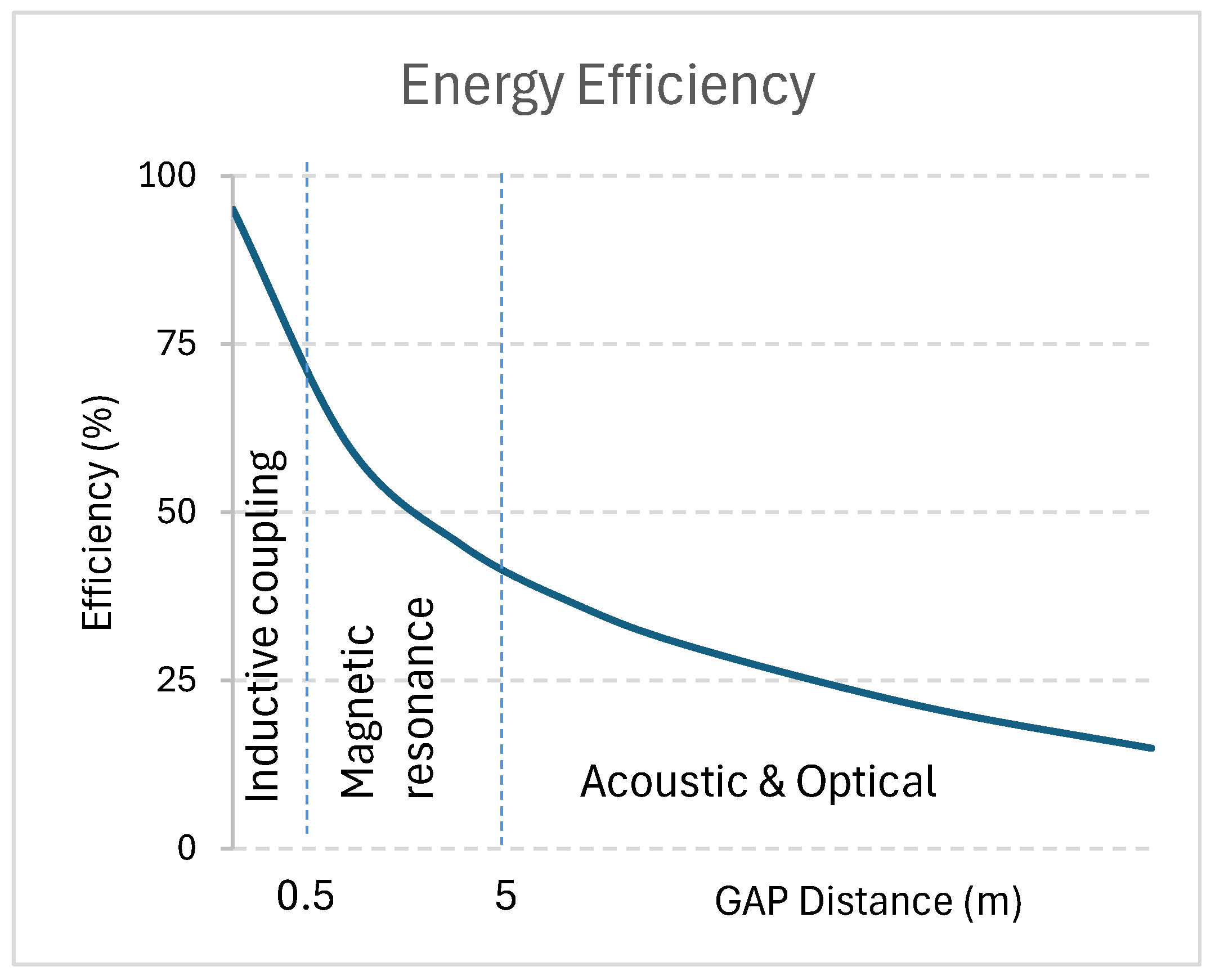
Inductive coupling and Magnetic Resonance have demonstrated the highest efficiencies in the literature, but they operate over relatively short ranges. In contrast, methods utilizing sound and light (ultrasonic and optical) can achieve longer ranges, albeit with lower efficiency. This trade-off is illustrated in Figure 17 [31].

5.3. The Trade-Off Between Efficiency and Distance

The trade-off between transfer efficiency and operational distance poses a significant obstacle in selecting an appropriate WPT method for underwater sensor networks. Short-range techniques (e.g., inductive coupling and magnetic resonance) provide high efficiency but require precise alignment, making them less effective for mobile or widely distributed networks. In contrast, longer-range methods (e.g., optical and ultrasonic WPT) enable greater flexibility but at the cost of lower efficiency.
One potential solution to this trade-off is the use of hybrid energy strategies. For instance, AUVs could serve as mobile power transporters, delivering energy to stationary sensors and other underwater devices through short-range WPT. However, this approach introduces other challenges, such as the energy cost of AUV mobility and the complexity of coordinating energy distribution across a network.
Another crucial aspect not addressed here is the sensitivity of various solutions to misalignment. An effective WPT method should not only cover the required distance and provide reasonable efficiency but also be resilient to device misalignment.
When assessing technological efficiency further, it will also require consideration of both installation and operational costs. While such cost analyses are critical for determining the most suitable solution for specific projects, they are beyond the scope of this article.

5.4. Future Research Directions

Two key research areas must be addressed to improve the feasibility of AUV-based energy transfer for underwater sensor networks:
  • Enhancing WPT Efficiency: Research is needed on optimizing beam-forming techniques, reconfigurable intelligent surfaces (RIS) [17,89,90,91], and adaptive transmitter–receiver configurations to improve power transfer efficiency in real-world underwater environments. This also presents an opportunity to examine cost estimates for the different solutions and how cost affects power efficiency.
  • Developing Intelligent AUV Control Systems: AUVs must be equipped with smart energy management systems that can monitor the energy status of multiple sensors and prioritize charging based on demand. Algorithms for optimizing charging schedules, minimizing energy loss, and adapting to environmental variations will be crucial for practical deployment.

5.5. Conclusions

The selection of an appropriate energy solution for underwater robotic sensor networks is highly dependent on environmental constraints, power requirements, and operational efficiency. While energy harvesting offers a sustainable approach, its dependence on natural conditions limits its applicability. WPT presents an alternative but comes with trade-offs between efficiency and range. Future research should focus on hybrid solutions that integrate WPT with intelligent energy distribution strategies, such as AUV-based charging, to create a more reliable and adaptable underwater power system.

Author Contributions

Conceptualization, S.J.N., S.E.T. and K.A.; methodology, S.J.N., S.E.T. and K.A.; validation, S.J.N., S.E.T. and K.A.; formal analysis, S.J.N.; investigation, S.J.N.; writing—original draft preparation, S.J.N.; writing—review and editing, S.J.N., S.E.T., and K.A.; visualization, S.J.N.; supervision, S.E.T.; project administration, K.A.; funding acquisition, K.A. All authors have read and agreed to the published version of the manuscript.

Funding

This project is funded by the Icelandic Research Fund, administered by Rannís—the Icelandic Centre for Research. This support comes in the form of Grant of Excellence No. 239994-051 for the project titled “HAF: Underwater Robotics Sensor Networks with Multi-Mode Devices and Remote Power Charging Capabilities”.

Data Availability Statement

The data extracted and analyzed during this review (study selection details, tables of characteristics, and summary results) are available from the corresponding author upon reasonable request.

Conflicts of Interest

The authors declare no conflicts of interest.

Abbreviations

The following abbreviations are used in this manuscript:
ACAlternating Current
AUVAutonomous Underwater Vehicles
DCDirect Current
EMIElectromagnetic Interference
EVsElectric Vehicles
IoTInternet of Things
IoUTInternet of Underwater Things
IWPTInductive Wireless Power Transfer
OEHOcean Energy Harvesting
OTECOcean Thermal Energy Conversion
OWPTOptical Wireless Power Transfer
MFCMicrobial Fuel Cells
PMSPower Management System
PVPhotovoltaic
PZTPiezoelectric transducer
RFRadio Frequency
RISReconfigurable Intelligent Surface
ROVRemotely operated vehicles
UWCNUnderwater Wireless Communication Network
UWPTUnderwater Wireless Power Transfer
WPTWireless Power Transfer

References

  1. Dao, N.-N.; Tu, N.H.; Thanh, T.T.; Bao, V.N.Q.; Na, W.; Cho, S. Neglected infrastructures for 6G—Underwater communications: How mature are they? J. Netw. Comput. Appl. 2023, 213, 103595. [Google Scholar] [CrossRef]
  2. Pompili, D.; Akyildiz, I. Overview of networking protocols for underwater wireless communications. IEEE Commun. Mag. 2009, 47, 97–102. [Google Scholar] [CrossRef]
  3. Lanbo, L.; Shengli, Z.; Jun-Hong, C. Prospects and problems of wireless communication for underwater sensor networks. Wirel. Commun. Mob. Comput. 2008, 8, 977–994. [Google Scholar] [CrossRef]
  4. Zhilin, I.V.; Bushnaq, O.M.; Masi, G.D.; Natalizio, E.; Akyildiz, I.F. A Universal Multimode (Acoustic, Magnetic Induction, Optical, RF) Software Defined Modem Architecture for Underwater Communication. IEEE Trans. Wirel. Commun. 2023, 22, 105–116. [Google Scholar] [CrossRef]
  5. Chen, B.; Hu, J.; Zhao, Y.; Ghosh, B.K. Finite-time observer based tracking control of uncertain heterogeneous underwater vehicles using adaptive sliding mode approach. Neurocomputing 2022, 481, 322–332. [Google Scholar] [CrossRef]
  6. Ding, F.; Wang, R.; Zhang, T.; Zheng, G.; Wu, Z.; Wang, S. Real-time Trajectory Planning and Tracking Control of Bionic Underwater Robot in Dynamic Environment. Cyborg Bionic Syst. 2024, 5, 0112. [Google Scholar] [CrossRef]
  7. Bushnaq, O.M.; Zhilin, I.V.; De Masi, G.; Natalizio, E.; Akyildiz, I.F. Automatic Network Slicing for Multi-Mode Internet of Underwater Things (MM-IoUT). In Proceedings of the GLOBECOM 2022-2022 IEEE Global Communications Conference, Rio de Janeiro, Brazil, 4–8 December 2022; pp. 6241–6246. [Google Scholar]
  8. Xie, L.; Shi, Y.; Hou, Y.T.; Lou, A. Wireless power transfer and applications to sensor networks. IEEE Wirel. Commun. 2013, 20, 140–145. [Google Scholar] [CrossRef]
  9. Garg, N.; Garg, R. Energy harvesting in IoT devices: A survey. In Proceedings of the 2017 International Conference on Intelligent Sustainable Systems (ICISS), Palladam, India, 7–8 December 2017; pp. 127–131. [Google Scholar]
  10. Crimmins, D.M.; Patty, C.T.; Beliard, M.A.; Baker, J.; Jalbert, J.C.; Komerska, R.J.; Chappell, S.G.; Blidberg, D.R. Long-Endurance Test Results of the Solar-Powered AUV System. In Proceedings of the OCEANS 2006, Boston, MA, USA, 18–21 September 2006; pp. 1–5. [Google Scholar]
  11. Teeneti, C.R.; Truscott, T.T.; Beal, D.N.; Pantic, Z. Review of Wireless Charging Systems for Autonomous Underwater Vehicles. IEEE J. Ocean. Eng. 2021, 46, 68–87. [Google Scholar] [CrossRef]
  12. Martínez de Alegría, I.; Rozas Holgado, I.; Ibarra, E.; Robles, E.; Martín, J.L. Wireless Power Transfer for Unmanned Underwater Vehicles: Technologies, Challenges and Applications. Energies 2024, 17, 2305. [Google Scholar] [CrossRef]
  13. Stokey, R.; Allen, B.; Austin, T.; Goldsborough, R.; Forrester, N.; Purcell, M.; Alt, C.v. Enabling technologies for REMUS docking: An integral component of an autonomous ocean-sampling network. IEEE J. Ocean. Eng. 2001, 26, 487–497. [Google Scholar] [CrossRef]
  14. Kesari Mary, D.R.; Ko, E.; Yoon, D.J.; Shin, S.-Y.; Park, S.-H. Energy Optimization Techniques in Underwater Internet of Things: Issues, State-of-the-Art, and Future Directions. Water 2022, 14, 3240. [Google Scholar] [CrossRef]
  15. Page, M.J.; McKenzie, J.E.; Bossuyt, P.M.; Boutron, I.; Hoffmann, T.C.; Mulrow, C.D.; Shamseer, L.; Tetzlaff, J.M.; Akl, E.A.; Brennan, S.E.; et al. The PRISMA 2020 statement: An updated guideline for reporting systematic reviews. BMJ 2021, 372, n71. [Google Scholar] [CrossRef] [PubMed]
  16. Islam, K.Y.; Ahmad, I.; Habibi, D.; Waqar, A. A survey on energy efficiency in underwater wireless communications. J. Netw. Comput. Appl. 2022, 198, 103295. [Google Scholar] [CrossRef]
  17. Wang, H.; Sun, Z.; Guo, H.; Wang, P.; Akyildiz, I.F. Designing Acoustic Reconfigurable Intelligent Surface for Underwater Communications. IEEE Trans. Wirel. Commun. 2023, 22, 8934–8948. [Google Scholar] [CrossRef]
  18. Wang, D.a.; Zhang, J.; Cui, S.; Bie, Z.; Chen, F.; Zhu, C. The state-of-the-arts of underwater wireless power transfer: A comprehensive review and new perspectives. Renew. Sustain. Energy Rev. 2024, 189, 113910. [Google Scholar] [CrossRef]
  19. Marra, G.; Fairweather, D.M.; Kamalov, V.; Gaynor, P.; Cantono, M.; Mulholland, S.; Baptie, B.; Castellanos, J.C.; Vagenas, G.; Gaudron, J.-O.; et al. Optical interferometry–based array of seafloor environmental sensors using a transoceanic submarine cable. Science 2022, 376, 874–879. [Google Scholar] [CrossRef]
  20. Yu, J.; Xu, P.; Yu, Z.; Wen, K.; Yang, J.; Wang, Y.; Qin, Y. Principles and Applications of Seismic Monitoring Based on Submarine Optical Cable. Sensors 2023, 23, 5600. [Google Scholar] [CrossRef]
  21. Guida, R.; Demirors, E.; Dave, N.; Melodia, T. Underwater Ultrasonic Wireless Power Transfer: A Battery-Less Platform for the Internet of Underwater Things. IEEE Trans. Mob. Comput. 2022, 21, 1861–1873. [Google Scholar] [CrossRef]
  22. Van Kleunen, W.A.P.; Moseley, N.A.; Havinga, P.J.M.; Meratnia, N. Proteus II: Design and Evaluation of an Integrated Power-Efficient Underwater Sensor Node. Int. J. Distrib. Sens. Netw. 2015, 2015, 1–10. [Google Scholar] [CrossRef]
  23. Dewan, A.; Ay, S.U.; Karim, M.N.; Beyenal, H. Alternative power sources for remote sensors: A review. J. Power Sources 2014, 245, 129–143. [Google Scholar] [CrossRef]
  24. Rémouit, F.; Ruiz-Minguela, P.; Engström, J. Review of Electrical Connectors for Underwater Applications. IEEE J. Ocean. Eng. 2018, 43, 1037–1047. [Google Scholar] [CrossRef]
  25. Alam, T.R.; Tchouaso, M.T.; Prelas, M.A. Summary of the design principles of betavoltaics and space applications. In Photovoltaics for Space; Elsevier: Amsterdam, The Netherlands, 2023; pp. 293–345. [Google Scholar]
  26. Altana, C.; Cottone, F.; Mengoni, D. First Simulations on Higher-Efficiency Betavoltaic Battery Integrated with Electrets for Space, Medicine and Remote Sensing Applications. In Proceedings of the 2022 21st International Conference on Micro and Nanotechnology for Power Generation and Energy Conversion Applications (PowerMEMS), Salt Lake City, UT, USA, 12–15 December 2022; pp. 245–247. [Google Scholar]
  27. Cuthbertson, A. Nuclear Battery Produces Power for 50 Years Without Needing to Charge. Independent UK Edition. 1 February 2024. Available online: https://www.independent.co.uk/tech/nuclear-battery-betavolt-atomic-china-b2476979.html (accessed on 2 November 2024).
  28. Xu, F.; Huang, H. Frequency selection for underwater wireless power transfer based on the analysis of eddy current loss. AEU-Int. J. Electron. Commun. 2023, 163, 154618. [Google Scholar] [CrossRef]
  29. Bang, K.; Park, S. Design and Characteristics of Underwater Stacked Capacitive Power Transfer Coupler and Analysis of Propagation in Water Medium. Appl. Sci. 2025, 15, 1901. [Google Scholar] [CrossRef]
  30. Webb, P. Introduction to Oceanography; Rebus Community: Montreal, QC, Canada, 2019. [Google Scholar]
  31. Mohsan, S.A.H.; Khan, M.A.; Mazinani, A.; Alsharif, M.H.; Cho, H.-S. Enabling Underwater Wireless Power Transfer towards Sixth Generation (6G) Wireless Networks: Opportunities, Recent Advances, and Technical Challenges. J. Mar. Sci. Eng. 2022, 10, 1282. [Google Scholar] [CrossRef]
  32. Lampitt, R.S. Marine Snow. In Encyclopedia of Ocean Sciences; Steele, J.H., Ed.; Academic Press: Oxford, UK, 2001; pp. 1667–1675. [Google Scholar]
  33. Detlefsen, C. About the Marianas/Geological Survey of Denmark and Greenland. Ingeniøren, 2 November 2013. [Google Scholar]
  34. Khan, M.Z.A.; Khan, H.A.; Aziz, M. Harvesting Energy from Ocean: Technologies and Perspectives. Energies 2022, 15, 3456. [Google Scholar] [CrossRef]
  35. Koca, K.; Kortenhaus, A.; Oumeraci, H.; Zanuttigh, B.; Angelelli, E.; Cantu, M.; Suffredini, R.; Franceschi, G. Recent advances in the development of wave energy converters. In Proceedings of the 9th European Wave and Tidal Energy Conference (EWTEC), Southampton, UK, 5–9 September 2011; pp. 2–5. [Google Scholar]
  36. Lu, Z.; Shang, J.; Luo, Z.; Zhu, Y.; Wang, M.; Wang, C. Research on environmental energy-driven intelligent unmanned underwater vehicles and their key technologies. In Proceedings of the 2021 IEEE 4th International Conference on Automation, Electronics and Electrical Engineering (AUTEEE), Shenyang, China, 19–21 November 2021; pp. 564–571. [Google Scholar]
  37. Jalbert, J.; Baker, J.; Duchesney, J.; Pietryka, P.; Dalton, W.; Blidberg, D.R.; Chappell, S.; Nitzel, R.; Holappa, K. A solar-powered autonomous underwater vehicle. In Proceedings of the Oceans 2003. Celebrating the Past… Teaming Toward the Future (IEEE Cat. No.03CH37492), San Diego, CA, USA, 22–26 September 2003; Volume 1132, pp. 1132–1140. [Google Scholar]
  38. Röhr, J.A.; Lipton, J.; Kong, J.; Maclean, S.A.; Taylor, A.D. Efficiency Limits of Underwater Solar Cells. Joule 2020, 4, 840–849. [Google Scholar] [CrossRef]
  39. Fukutani, K.; Kanbe, M.; Futako, W.; Kaplan, B.; Kamiya, T.; Fortmann, C.M.; Shimizu, I. Band gap tuning of a-Si:H from 1.55 eV to 2.10 eV by intentionally promoting structural relaxation. J. Non-Cryst. Solids 1998, 227–230, 63–67. [Google Scholar] [CrossRef]
  40. Baumeister, P.W. Optical absorption of cuprous oxide. Phys. Rev. 1961, 121, 359. [Google Scholar] [CrossRef]
  41. Chu, T.; Chu, S.; Ferekides, C.; Britt, J. Films and junctions of cadmium zinc telluride. J. Appl. Phys. 1992, 71, 5635–5640. [Google Scholar] [CrossRef]
  42. Sarswat, P.K.; Free, M.L. Enhanced photoelectrochemical response from copper antimony zinc sulfide thin films on transparent conducting electrode. Int. J. Photoenergy 2013, 2013, 154694. [Google Scholar] [CrossRef]
  43. El Allali, M.; So, C.; Veje, E.; Tidemand-Petersson, P. Experimental determination of the GaAs and Ga1−xAlxAs band-gap energy dependence on temperature and aluminum mole fraction in the direct band-gap region. Phys. Rev. B 1993, 48, 4398. [Google Scholar] [CrossRef]
  44. Tomasulo, S.; Nay Yaung, K.; Faucher, J.; Vaisman, M.; Lee, M. Metamorphic 2.1–2.2 eV InGaP solar cells on GaP substrates. Appl. Phys. Lett. 2014, 104, 173903. [Google Scholar] [CrossRef]
  45. Grassman, T.J.; Carlin, A.M.; Grandal, J.; Ratcliff, C.; Yang, L.; Mills, M.J.; Ringel, S.A. Spectrum-optimized Si-based III-V multijunction photovoltaics. In Proceedings of the Physics, Simulation, and Photonic Engineering of Photovoltaic Devices, San Francisco, CA, USA, 21–26 February 2012; pp. 130–135. [Google Scholar]
  46. Kamal, S.; Al-sayyad, G.M.; Abdelmoteleb, R.; Abdellatif, M.; Abdellatif, S.O. Submerged Solar Energy Harvesters Performance for Underwater Applications. In Proceedings of the 2019 International Conference on Innovative Trends in Computer Engineering (ITCE), Aswan, Egypt, 2–4 February 2019; pp. 444–449. [Google Scholar]
  47. Rosli, R.; Dimla, E. A review of tidal current energy resource assessment: Current status and trend. In Proceedings of the 2018 5th International Conference on Renewable Energy: Generation and Applications (ICREGA), Al Ain, United Arab Emirates, 25–28 February 2018; pp. 34–40. [Google Scholar]
  48. Kadiri, M.; Ahmadian, R.; Bockelmann-Evans, B.; Falconer, R.A.; Kay, D. An assessment of the impacts of a tidal renewable energy scheme on the eutrophication potential of the Severn Estuary, UK. Comput. Geosci. 2014, 71, 3–10. [Google Scholar] [CrossRef]
  49. Alvarez, E.A.; Rico-Secades, M.; Suárez, D.F.; Gutiérrez-Trashorras, A.J.; Fernández-Francos, J. Obtaining energy from tidal microturbines: A practical example in the Nalón River. Appl. Energy 2016, 183, 100–112. [Google Scholar] [CrossRef]
  50. Khan, A.; Imran, M.; Alharbi, A.; Mohamed, E.M.; Fouda, M.M. Energy Harvesting in Underwater Acoustic Wireless Sensor Networks: Design, Taxonomy, Applications, Challenges and Future Directions. IEEE Access 2022, 10, 134606–134622. [Google Scholar] [CrossRef]
  51. Chao, Y. Autonomous underwater vehicles and sensors powered by ocean thermal energy. In Proceedings of the OCEANS 2016-Shanghai, Shanghai, China, 10–13 April 2016; pp. 1–4. [Google Scholar]
  52. Haldeman, C.D.; Schofield, O.; Webb, D.C.; Valdez, T.I.; Jones, J.A. Implementation of energy harvesting system for powering thermal gliders for long duration ocean research. In Proceedings of the OCEANS 2015-MTS/IEEE Washington, Washington, DC, USA, 19–22 October 2015; pp. 1–5. [Google Scholar]
  53. Domingo, M.C. An overview of the internet of underwater things. J. Netw. Comput. Appl. 2012, 35, 1879–1890. [Google Scholar] [CrossRef]
  54. Rabaey, K.; Verstraete, W. Microbial fuel cells: Novel biotechnology for energy generation. Trends Biotechnol. 2005, 23, 291–298. [Google Scholar] [CrossRef]
  55. Dai, J.; Li, X.; Li, B.; Wang, L. Design and modeling of an underwater energy harvesting system. In Proceedings of the International Symposium on Circuits and Systems (ISCAS), Rio de Janeiro, Brazil, 15–18 May 2011. [Google Scholar]
  56. Donovan, C.; Dewan, A.; Peng, H.; Heo, D.; Beyenal, H. Power management system for a 2.5W remote sensor powered by a sediment microbial fuel cell. J. Power Sources 2011, 196, 1171–1177. [Google Scholar] [CrossRef]
  57. Li, Z.; Roscow, J.; Khanbareh, H.; Haswell, G.; Bowen, C. Energy Harvesting from Water Flow by Using Piezoelectric Materials. Adv. Energy Sustain. Res. 2024, 5, 2300235. [Google Scholar] [CrossRef]
  58. Hui, S.Y.R.; Ho, W.W.C. A new generation of universal contactless Battery Charging platform for portable Consumer Electronic equipment. IEEE Trans. Power Electron. 2005, 20, 620–627. [Google Scholar] [CrossRef]
  59. Ko, Y.D.; Jang, Y.J. The Optimal System Design of the Online Electric Vehicle Utilizing Wireless Power Transmission Technology. IEEE Trans. Intell. Transp. Syst. 2013, 14, 1255–1265. [Google Scholar] [CrossRef]
  60. Li, Z.-S.; Li, D.-J.; Lin, L.; Chen, Y. Design considerations for electromagnetic couplers in contactless power transmission systems for deep-sea applications. J. Zhejiang Univ. Sci. C 2010, 11, 824–834. [Google Scholar] [CrossRef]
  61. Feezor, M.D.; Sorrell, F.Y.; Blankinship, P.R. An interface system for autonomous undersea vehicles. IEEE J. Ocean. Eng. 2001, 26, 522–525. [Google Scholar] [CrossRef]
  62. McGinnis, T.; Henze, C.P.; Conroy, K. Inductive Power System for Autonomous Underwater Vehicles. In Proceedings of the OCEANS 2007, Vancouver, BC, Canada, 29 September–4 October 2007; pp. 1–5. [Google Scholar]
  63. Wang, S.-l.; Song, B.-w.; Duan, G.-l.; Du, X.-z. Automatic wireless power supply system to autonomous underwater vehicles by means of electromagnetic coupler. J. Shanghai Jiaotong Univ. (Sci.) 2014, 19, 110–114. [Google Scholar] [CrossRef]
  64. Anyapo, C.; Intani, P. Wireless Power Transfer for Autonomous Underwater Vehicle. In Proceedings of the 2020 IEEE PELS Workshop on Emerging Technologies: Wireless Power Transfer (WoW), Seoul, Republic of Korea, 15–19 November 2020; pp. 246–249. [Google Scholar]
  65. Pessoa, L.M.; Pereira, M.R.; Santos, H.M.; Salgado, H.M. Simulation and experimental evaluation of a resonant magnetic wireless power transfer system for seawater operation. In Proceedings of the OCEANS 2016-Shanghai, Shanghai, China, 10–13 April 2016; pp. 1–5. [Google Scholar]
  66. Yang, L.; Li, X.; Zhang, Y.; Feng, B.; Yang, T.; Wen, H.; Tian, J.; Zhu, D.; Huang, J.; Zhang, A.; et al. A review of underwater inductive wireless power transfer system. IET Power Electron. 2024, 17, 894–905. [Google Scholar] [CrossRef]
  67. Kan, T.; Mai, R.; Mercier, P.P.; Mi, C.C. Design and Analysis of a Three-Phase Wireless Charging System for Lightweight Autonomous Underwater Vehicles. IEEE Trans. Power Electron. 2018, 33, 6622–6632. [Google Scholar] [CrossRef]
  68. Shi, J.-G.; Li, D.-J.; Yang, C.-J. Design and analysis of an underwater inductive coupling power transfer system for autonomous underwater vehicle docking applications. J. Zhejiang Univ. Sci. C 2014, 15, 51–62. [Google Scholar] [CrossRef]
  69. Shizuno, K.; Yoshida, S.; Tanomura, M.; Hama, Y. Long distance high efficient underwater wireless charging system using dielectric-assist antenna. In Proceedings of the 2014 Oceans-St. John’s, St. John’s, NL, Canada, 14–19 September 2014; pp. 1–3. [Google Scholar]
  70. Yoshida, S.; Tanomura, M.; Hama, Y.; Hirose, T.; Suzuki, A.; Matsui, Y.; Sogo, N.; Sato, R. Underwater wireless power transfer for non-fixed unmanned underwater vehicle in the ocean. In Proceedings of the 2016 IEEE/OES Autonomous Underwater Vehicles (AUV), Tokyo, Japan, 6–9 November 2016; pp. 177–180. [Google Scholar]
  71. Hui, S.Y.R.; Zhong, W.; Lee, C.K. A Critical Review of Recent Progress in Mid-Range Wireless Power Transfer. IEEE Trans. Power Electron. 2014, 29, 4500–4511. [Google Scholar] [CrossRef]
  72. Kurs, A.; Karalis, A.; Moffatt, R.; Joannopoulos, J.D.; Fisher, P.; Soljačić, M. Wireless Power Transfer via Strongly Coupled Magnetic Resonances. Science 2007, 317, 83–86. [Google Scholar] [CrossRef]
  73. Mohsan, S.A.H.; Islam, A.; Ali, M.; Mahmood, A.; Selsabil, L.; Mazinani, A.; Amjad, H. A Review on Research Challenges, Limitations and Practical Solutions for Underwater Wireless Power Transfer. Int. J. Adv. Comput. Sci. Appl. 2020, 11, 554–562. [Google Scholar] [CrossRef]
  74. Yu, L.; Sun, H.; Su, S.; Tang, H.; Sun, H.; Zhang, X. Review of Crucial Problems of Underwater Wireless Power Transmission. Electronics 2023, 12, 163. [Google Scholar] [CrossRef]
  75. Jadidian, J.; Katabi, D. Magnetic MIMO: How to charge your phone in your pocket. In Proceedings of the MobiCom’14: The 20th Annual International Conference on Mobile Computing and Networking, Maui, HI, USA, 7–11 September 2014; pp. 495–506. [Google Scholar]
  76. Wibisono, A.; Alsharif, M.H.; Song, H.-K.; Lee, B.M. A Survey on Underwater Wireless Power and Data Transfer System. IEEE Access 2024, 12, 34942–34957. [Google Scholar] [CrossRef]
  77. Afzal, S.S.; Akbar, W.; Rodriguez, O.; Doumet, M.; Ha, U.; Ghaffarivardavagh, R.; Adib, F. Battery-free wireless imaging of underwater environments. Nat. Commun. 2022, 13, 5546. [Google Scholar] [CrossRef] [PubMed]
  78. Akafua, J.; Chapman, R.; Guo, H. A Design of Wireless Communication and Wireless Energy Transfer System for In-Pipe Robots. In Proceedings of the 2021 IEEE International Conference on Wireless for Space and Extreme Environments (WiSEE), Cleveland, OH, USA, 12–14 October 2021; pp. 84–89. [Google Scholar]
  79. Zhao, Y.; Du, Y.; Wang, Z.; Wang, J.; Geng, Y. Design of Ultrasonic Transducer Structure for Underwater Wireless Power Transfer System. In Proceedings of the 2021 IEEE Wireless Power Transfer Conference (WPTC), San Diego, CA, USA, 1–4 June 2021; pp. 1–4. [Google Scholar]
  80. Chen, X.; Xu, K.; Mu, X.; Li, G. Comparisons of inductive coupling and ultrasonic coupling wireless power transfer under seawater. Dianji Yu Kongzhi Xuebao/Electr. Mach. Control 2018, 22, 9–16. [Google Scholar]
  81. Pinuela, M.; Yates, D.C.; Lucyszyn, S.; Mitcheson, P.D. Maximizing DC-to-Load Efficiency for Inductive Power Transfer. IEEE Trans. Power Electron. 2013, 28, 2437–2447. [Google Scholar] [CrossRef]
  82. Kim, S.-M.; Kwon, D. Transfer Efficiency of Underwater Optical Wireless Power Transmission Depending on the Operating Wavelength. Curr. Opt. Photon. 2020, 4, 571–575. [Google Scholar] [CrossRef]
  83. Lyu, W.; Li, X.; Zhang, Y.; Guan, X.; Zhang, Z.; Xu, J. Experimental demonstration of underwater wireless optical OFDM communication system with a single SPAD receiver. Opt. Commun. 2022, 508, 127767. [Google Scholar] [CrossRef]
  84. Liu, Q.; Wu, J.; Xia, P.; Zhao, S.; Chen, W.; Yang, Y.; Hanzo, L. Charging Unplugged: Will Distributed Laser Charging for Mobile Wireless Power Transfer Work? IEEE Veh. Technol. Mag. 2016, 11, 36–45. [Google Scholar] [CrossRef]
  85. Hajimiri, A.; Abiri, B.; Bohn, F.; Gal-Katziri, M.; Manohara, M.H. Dynamic Focusing of Large Arrays for Wireless Power Transfer and Beyond. IEEE J. Solid-State Circuits 2021, 56, 2077–2101. [Google Scholar] [CrossRef]
  86. Wu, T.-C.; Chi, Y.-C.; Wang, H.-Y.; Tsai, C.-T.; Lin, G.-R. Blue Laser Diode Enables Underwater Communication at 12.4 Gbps. Sci. Rep. 2017, 7, 40480. [Google Scholar] [CrossRef]
  87. Zhang, B.; Xu, W.; Lu, C.; Lu, Y.; Wang, X. Review of low-loss wireless power transfer methods for autonomous underwater vehicles. IET Power Electron. 2022, 15, 775–788. [Google Scholar] [CrossRef]
  88. Karalis, A.; Joannopoulos, J.D.; Soljačić, M. Efficient wireless non-radiative mid-range energy transfer. Ann. Phys. 2008, 323, 34–48. [Google Scholar] [CrossRef]
  89. Kisseleff, S.; Akyildiz, I.F.; Gerstacker, W.H. Magnetic Induction-Based Simultaneous Wireless Information and Power Transfer for Single Information and Multiple Power Receivers. IEEE Trans. Commun. 2017, 65, 1396–1410. [Google Scholar] [CrossRef]
  90. Sun, Z.; Guo, H.; Akyildiz, I.F. High-Data-Rate Long-Range Underwater Communications via Acoustic Reconfigurable Intelligent Surfaces. IEEE Commun. Mag. 2022, 60, 96–102. [Google Scholar] [CrossRef]
  91. Yang, G.; Moghadam, M.R.V.; Zhang, R. Magnetic MIMO Signal Processing and Optimization for Wireless Power Transfer. IEEE Trans. Signal Process. 2017, 65, 2860–2874. [Google Scholar] [CrossRef]
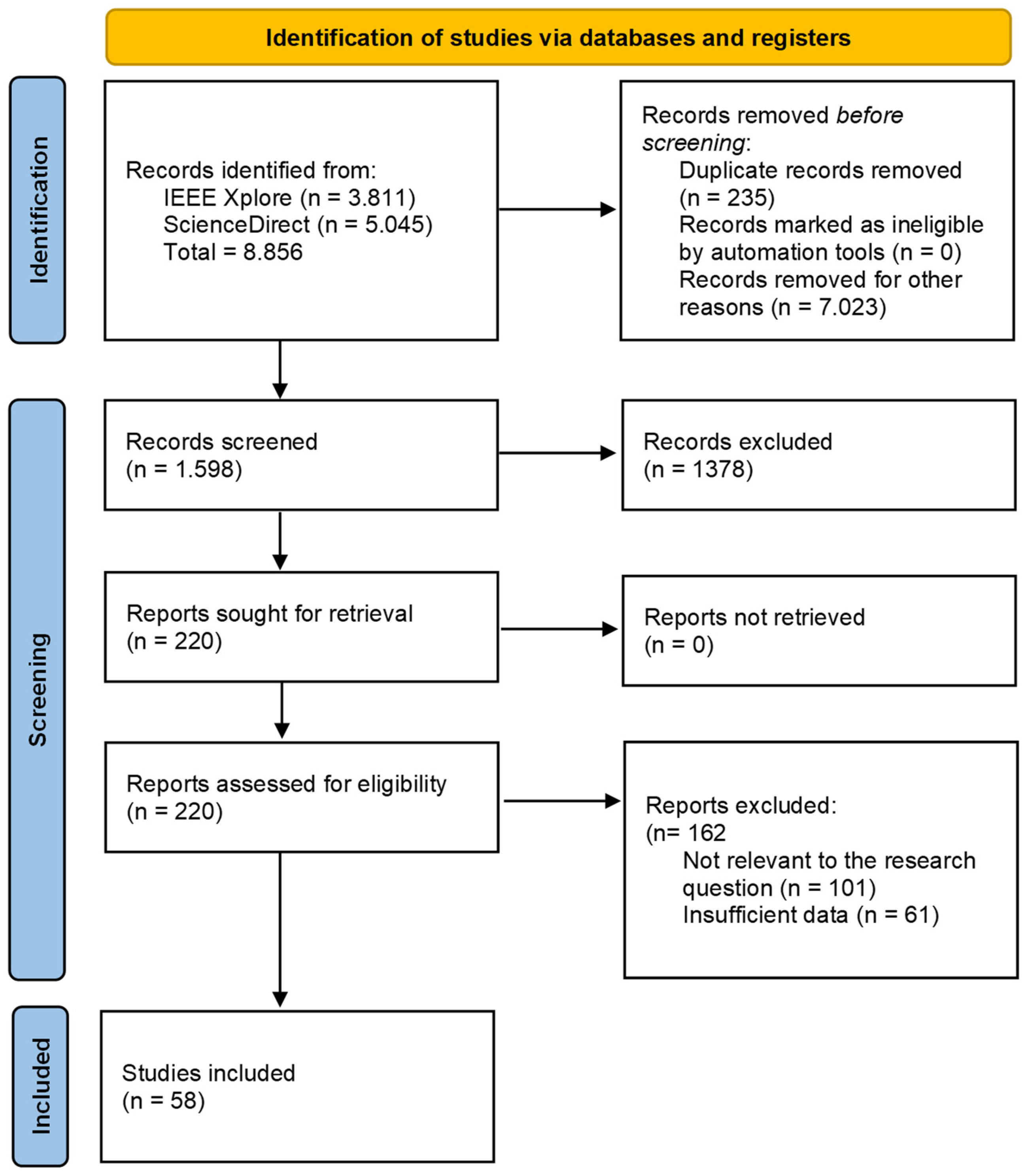
Figure 1. The flow chart of a systematic review according to PRISMA, showing the three steps of identification, screening, and inclusion [15].
Jmse 13 01728 g001
Figure 2. Underwater robotic sensor network architecture.
Jmse 13 01728 g002
Figure 3. Various methods for powering devices in the underwater environment.
Jmse 13 01728 g003
Figure 4. The five ocean layers of depth [30].
Jmse 13 01728 g004
Figure 5. Six types of ship motion.
Jmse 13 01728 g005
Figure 6. Two power harvesting methods from the power of ocean waves: (a) the concept of a wave-activated body and (b) two types of point absorbers: submerged body and floating body.
Jmse 13 01728 g006
Figure 7. An underwater device with a solar panel and a graph showing the energy efficiencies at several depths for different band gaps of the solar cell (affected by wavelengths of the solar spectrum) (Reprinted from Joule, Volume 4, Issue 4, Jason A. Röhr, Jason Lipton, Jaemin Kong, Stephen A. Maclean, André D. Taylor, Efficiency Limits of Underwater Solar Cells, Pages 840–849, Copyright (2020), with permission from Elsevier) [38].
Jmse 13 01728 g007
Figure 8. Working principles of different tidal current technologies: (a) horizontal axis tidal current turbines, (b) vertical axis tidal current turbines, and (c) enclosed turbines [34].
Jmse 13 01728 g008
Figure 9. Conceptual diagram of a closed-cycle Ocean Thermal Energy Conversion (OTEC) system.
Jmse 13 01728 g009
Figure 10. Conceptual diagram of an MFC, where the power source is microbes in the sediments that generate electrons by breaking down organic matter through an oxidation process.
Jmse 13 01728 g010
Figure 11. Schematic representations of various structures designed to harness energy using piezoelectric materials: (a) direct blocking through pressure fluctuations and wave motions utilizing a buoy; (b) vibration induced by cavity flow with rotation; (c) vibration caused by pressure fluctuations; (d) cavity flow-induced vibration using an ‘eel’; and (e) fluid forces resulting from the motion of a bluff body.
Jmse 13 01728 g011
Figure 12. Schematic circuit diagram of contactless power transmission using inductive coupling for a charging system.
Jmse 13 01728 g012
Figure 13. Wireless Power Transmission using inductive coupling in an underwater context, where an AUV is either charging by resting on a station connected to a land-based energy source or floating beneath a station linked to a buoy.
Jmse 13 01728 g013
Figure 14. A schematic circuit diagram that shares similarities with Figure 12 but incorporates “Resonant Circuits”. These circuits enable the transmitting circuit (the primary coil) and the receiving circuit (the secondary coil) to resonate at the same frequency.
Jmse 13 01728 g014
Figure 15. Ultrasonic/Acoustic WPT.
Jmse 13 01728 g015
Figure 16. Optical Wireless Power Transfer.
Jmse 13 01728 g016
Figure 17. Transfer efficiency for WPT techniques [31].
Jmse 13 01728 g017
Table 1. Environmental factors affecting underwater technologies.
Environmental FactorEffects on Technical Devices
SunlightNatural sunlight does not penetrate deep into the ocean. The first 200 m, known as the sunlight zone, provides some opportunities for utilizing solar energy. For instance, plants convert sunlight into food through photosynthesis [32]. Research has explored various solar energy options available beneath the water’s surface.
TemperatureOcean temperatures range from approximately −2 °C to 30 °C. The warmest waters are typically found at the surface in tropical regions, while surface waters near the poles are much colder. Despite the warmth of surface waters, most ocean water is deeper and frigid, resulting in an average temperature of about 4 °C. The temperature remains relatively constant in the upper 100–200 m, called the mixed layer. Below this layer is a sharp temperature drop over a relatively small depth increase known as the thermocline. Beyond the thermocline, the temperature in the deep ocean stabilizes around 2 °C, extending to the ocean floor, making it one of Earth’s most thermally stable regions [30]
PressureThe pressure in the ocean increases by approximately 1 atmosphere for every 10 m of depth. Consequently, the ocean depths are subject to extreme pressures, often ranging from 40 to over 100 times the pressure of Earth’s atmosphere [3,30].
SalinitySalinity remains remarkably constant throughout the deep sea, averaging about 35 parts per thousand. While there are minor variations in salinity, they are generally insignificant, except in large landlocked seas such as the Mediterranean and the Red Sea [33].
Water CurrentWater currents can serve as a potential energy source; however, they also pose challenges as they can affect the usability and performance of technical devices. Ocean currents may displace devices within the sea, leading to destabilization, such as the misalignment of transmitter and receiver coils used for WPT [21].
BiofoulingMicroorganisms thrive in aquatic environments, and their growth on devices can result in misalignment and increased gaps between components. Literature suggests that heating can reduce biofouling, and specialized antifouling coatings may also be effective [31].
Table 2. Various OEH techniques and their advantages and disadvantages.
Ocean Energy Harvesting Techniques
TechniqueProsCons
WavesProvides a continuous and predictable energy source, as wave patterns can be forecasted.
High energy density.
Installation and maintenance can be challenging due to harsh environmental conditions.
Requires extensive knowledge of ocean dynamics.
Solar EnergyHigh availability, particularly in areas with consistent sunlight (e.g., tropics).
Scalable with low environmental impact.
Limited efficiency due to reduced sunlight reaching floating cells.
Deep waters make this option less viable.
Kinetic Energy of WaterOffers a predictable and consistent energy source, especially from tidal flows.
High energy density, as ocean currents and tides carry significant kinetic energy.
Primarily applicable in specific geographic regions with strong currents or tidal flows.
Maintenance can be complex and costly.
Potential disruption to marine life and navigation.
Temperature VariationsA proven and reliable energy source in tropical regions where temperature gradients are consistent.Applicable in regions with significant temperature gradients between the surface and deep waters.
It may pose risks to marine ecosystems due to the disruption of the mixing of water layers.
Fuel CellsLow environmental impact, as they rely on organic materials and microbes.
It can serve as a power source for underwater sensors and autonomous systems with minimal energy needs.
Limited power output; more suitable for small, low-power applications.
Efficiency depends on local sediment composition and microbial activity.
Susceptible to biofouling, which reduces efficiency over time.
Piezoelectric MaterialConverts mechanical stress from waves or currents into electricity.
Minimal environmental impact when placed strategically.
Can autonomously power small, low-energy devices.
Currently, low power output makes it inefficient for large-scale energy needs.
Durability concerns, as piezoelectric materials may degrade in harsh marine conditions.
Costly and limited to specific applications rather than broad-scale energy production.
Table 3. OEH techniques: a summary of the literature.
TechniqueReferenceMain ContributionLimitations
WavesM.Z.A. Khan (2022) [34]Overview of wave energy technologies in the broader ocean energy context.Not only wave energy nor a comparison of the methods. Has limited technical depth in the conclusion.
K. Koca (2013) [35]Focused review of wave energy converters (WECs).Good overview for its time, but it was published more than 10 years ago.
Z. Lu
(2021) [36]
Discusses key technologies possible for UUVs to be powered by environmental energy sources.Lack of specificity on wave energy harvesting and absence of experimental validation.
Solar EnergyLu [36]
(2021)
Environmental energy use in UUVs, including solar.Focused on vehicle systems, not solar tech itself or validation of solar harvesting underwater.
J. Jalbert [37] (2003)An early prototype of a solar-powered AUV was tested in shallow waters.Limited operational depth and published more than 20 years ago make it limited as a state-of-the-art solution.
Fukutani [39] (1998)Tuning the a-Si:H band gap for solar cell optimization.Material-level research; no testing in water/ocean environments or device applications.
Sarswat & Free [42] (2013)Enhanced photoelectrochemical response for solar applications, with potential underwater relevance.No specific underwater validation; tested only in controlled (dry) lab conditions.
Tomasulo [44] (2014)Designed high-bandgap solar cells suitable for shallow water.Device performance not tested in marine or submerged environments.
Kinetic Energy of WaterR. Rosli & E. Dimla [47] (2018)Reviews the methodologies for assessing tidal current energy resourcesConcentrates on resource assessment rather than device technology or efficiency
M. Kadiri [48] (2014)Investigates the environmental impacts of tidal energy schemes.May not generalize to other locations or device types; mainly evaluates environmental impact, not energy extraction performance.
Alvarez [49] (2016)Presents a practical implementation of tidal microturbines for energy harvesting, providing real-world performance data.Small-scale and very localized, it lacks generalizability and upscaling possibilities.
Temperature VariationsY. Chao [51] (2016)Describes the use of ocean thermal energy to power AUVs and sensors.No performance results provided and scalability not fully addressed.
Haldeman [52] (2015)Demonstrates thermal-powered gliders for long-duration missions.Field deployment demonstrated, but optimization for varying ocean conditions is still needed
Domingo [53] (2012)Explores thermal strategies for IoUT.High-level review; no experimental data, and an over 10-year-old publication.
Fuel CellsGuida [21] (2022)Develops an underwater ultrasonic WPT system; briefly mentions MFCs as a complementary technology.The main focus is wireless acoustics; MFCs are discussed only superficially.
Domingo [53] (2012)High-level overview of IoUT, suggesting MFCs as an energy harvesting method.Lacks technical analysis, experimental data, or performance evaluations.
Rabaey and Verstraete [54] (2005)Detailed review of MFCs, including mechanisms, potential, and applications in biotechnology.Focus on terrestrial and wastewater contexts; marine-specific challenges are not addressed.
Dai [55] (2011)Proposed design and modeling of underwater energy systems, including using MFCs for underwater harvesting.No experimental validation or field testing; model-driven study.
Donovan [56] (2011)Designs a PMS for sensors powered by a sediment MFC, for practical small-scale deployment.Limited to low-power (2.5 W) systems; scalability and harsh marine deployment not fully explored.
A. Khan [50] (2022)MFCs as energy solutions for remote underwater networks.Early-stage, low power outputs
Piezoelectric MaterialsM.Z.A. Khan [34] (2022)Discusses piezoelectric energy harvesting as one of the ocean energy technologiesComprehensive overview; no technical depth
A. Dewan [23] (2014)Reviews power sources for remote sensors; includes piezoelectric materials for EH in aquatic environments.General review: limited experimental insights into marine-specific implementations
Z. Li [57] (2024)Focuses on EH from water flow using piezoelectric materials; experimental validation of material performance.Early-stage research; challenges remain regarding scaling to higher power outputs.
Table 4. OEH techniques: a further summary of the literature indicating the expected power levels from the applied techniques.
TechniqueReferencePower LevelComments
WavesM.Z.A. Khan (2022) [34]20–500 kWFixed and floating
M.Z.A. Khan (2022) [34]150 kWFloating Wave-Activated Bodies
Solar EnergyLu (2021) [36]60–170 W (0.5–1 m2)On the ocean surface
Jalbert (2003) [37]85 W
Röhr (2020) [38]5 mW/cm2Under the ocean surface
A. Khan (2022) [50]55–125 W
Kinetic Energy of WaterDewan (2014) [23]1 W (water velocity 1 m/s)Energy Harvesting Eel
R. Rosli (2018) [47]1–2 MWFloating
A. Khan (2022) [50]1–9 kW
Temperature VariationsChao (2016) [51] 200 WIn 30 sec
Haldeman (2015) [52]220 W
Fuel CellsDewan (2014) [23]3.5 mWAverage continuous generation
Rabaey (2005) [54]1 kW/per m3
Donovan (2011) [56]2.5 WIn short power bursts
Piezoelectric MaterialsDewan (2014) [23]0.03–3.5 mW
A. Khan (2022) [50]2–20 W
Li (2024) [57]1 mW
Table 5. Comparison of inductive coupling solutions that have been tested, showing their relatively short ranges and efficiencies.
DescriptionAuthorsPower Level (W)Efficiency (%)Gap Distance (cm)
Electromagnetic couplersLi, Zs. [60]400900.2
Inductive power for AUVMcGinnis [62]250700.2
Electromagnetic coupler
for AUV
Wang [63]500880.6–1
Three-phase WPTKan [67]1000922.1
Inductive coupling power transfer systemShi [68]45840.9
Table 6. A comparison of some Magnetic Resonance solutions is shown below.
DescriptionAuthorsPower Level (W)Efficiency (%)Gap Distance (cm)
Resonant magnetic
WPT coil config
Pessoa [65]-60%5
Resonant magnetic
WPT spiral config
Pessoa [65]-75%5
WPT with dielectric-assist antennaShizuno [69]-60%10
WPT Antenna TechnologyYoshida [70]2565%10
Mid-Range WPTHui [71]0.0140%200
WPT via strongly coupled magnetic resonance Kurs [72]6040%200
Powering a halogen lampTeeneti [11]300080%26
Table 7. A comparison of some ultrasonic/acoustic WPT studies is shown below.
DescriptionAuthorsYearPower Level (W)Efficiency (%)Gap Distance (cm)
Ultrasonic Wireless Power TransferGuida [21]202214100
Battery-free wireless imaging of underwater environmentsAfzal [77]202210−4-100
Ultrasonic Transducer Structure for Underwater WPTZhao [79]2021-7810
Comparisons of inductive coupling and ultrasonic coupling WPT under seawaterChen and Xu [80]201850315
Maximizing DC to load efficiency for inductive power transferM. Pinuela [81]20131057730
Table 8. A comparison of some Optical WPTs is shown below.
DescriptionAuthorsPower Level (W)Efficiency (%)Gap Distance (cm)
Underwater wireless optical communication Lyu [83]0.0005 30700
Underwater Optical WPT for the Wavelength 660 nm (red light)Kim [82]0.51–30–300
Underwater Optical WPT for the Wavelength 405 nm (blue light)Kim [82]11500–1000
Laser charging for Mobile WPT in the airLiu [84]210–301000
Focusing on large arrays for WPTHajimiri [85]263100
Table 9. WPT techniques in water: a summary of the literature.
TechniqueReferenceMain ContributionLimitations
Inductive CouplingZ.-s. Li [60] (2010)Design principles for electromagnetic couplers in deep-sea WPT systems.Lacks empirical validation in marine conditions.
M. D. Feezor [61] (2001)Early development of interface systems for AUVs using inductive coupling.Obsolete by current standards; limited to early-stage prototypes.
T. McGinnis [62] (2007)Describes a practical inductive power system for AUVs.Efficiency and misalignment issues are not comprehensively addressed.
S.-l. Wang [63] (2014)Automatic wireless power system using electromagnetic coupler for AUVs.Simplified test environment; lacks efficiency comparisons and performance benchmarking.
Anyapo and Intani [64] (2020)Exploration of the WPT system for AUVs, tested in lab settings.Early-stage prototype; not validated in real underwater scenarios.
J.-g. Shi [68] (2014)Design and analysis of an underwater inductive system for AUV docking.Effective but limited to docking scenarios.
Magnetic ResonanceYu et al. [74] (2023)Comprehensive review of challenges and proposed solutions for magnetic resonance in underwater environments.Review-based; lacks new experimental validation or full system implementations.
Jadidian and Katabi [75] (2014)Introduced magnetic MIMO to enable spatial freedom in Magnetic Resonance-based charging.Focused on consumer devices, not marine; performance in underwater media not validated.
Yoshida et al. [70] (2016)Demonstrated Magnetic Resonance WPT for mobile UUVs, showing adaptability in marine environments.Challenges remain in maintaining resonance and alignment during mobility and limited distance.
Kurs et al. [72] (2007)Pioneered the concept of strongly coupled Magnetic Resonance for mid-range WPT.Proof-of-concept; not applied to underwater environments; efficiency drop in conductive media like seawater.
Ultrasonic/Acoustic WPTA. Wibisono [76] (2024)A comprehensive survey on underwater WPT and data transfer using various methods, including acoustics Primarily theoretical; lacks detailed performance metrics or experimental validations for acoustic WPT.
Y. Zhao et al. [79] (2021)A new ultrasonic transducer design optimized for underwater WPT, focused on structural configuration.Focused only on transducer design; limited experimental results on long-distance performance.
X. Chen et al. [80] (2018)A comparative study between inductive and ultrasonic WPT in seawater provides insight into efficiency under different conditions.Limited to specific lab conditions; lacks broad applicability across different underwater scenarios.
M. Pinuela [81] (2013)Addresses efficiency in inductive systems, providing useful comparisons for acoustic systems.Not directly focused on ultrasonic transfer, acoustic applications are not the primary concern.
J. Akafua [78] (2021)Designs a system for in-pipe robots that includes both wireless communication and energy transfer via acoustics.Application specific; lacks generalization to broader underwater WPT use cases.
Optical WPTKim [82] (2020)Studied underwater Optical WPT efficiency across different wavelengthsLimited to theoretical and simulation analysis; lacks real-world validation.
W. Lyu [83]. (2022)Demonstrated underwater optical OFDM communication using SPAD receiver.Focuses on data transfer, not power; narrow scope for WPT relevance.
Q. Liu et al. [84] (2016)Introduction of Distributed Laser Charging (DLC), analyzing its feasibility for mobile WPT.Terrestrial and aerial context; limited discussion on underwater propagation or attenuation.
A. Hajimiri [85] (2021)Proposed techniques for beam forming for dynamic optical power deliverySystem complexity is high; underwater adaptation remains untested.
T.-C. Wu [86] (2017)Blue laser communication at high data rates underwater shows potential for high-efficiency transfer.Limited to the communication use case; lacks a power transmission focus.
Table 10. Various methods for underwater WPT.
Wireless Power Transfer (WPT)Power (W)Efficiency %GAP Distance
Inductive coupling200–10,00080–90%0–2 cm
Magnetic Resonance10–100065–80%5–25 cm
Ultrasonic WPT12–5%1 m
Optical WPT0.001–11–3%5–10 m
Disclaimer/Publisher’s Note: The statements, opinions and data contained in all publications are solely those of the individual author(s) and contributor(s) and not of MDPI and/or the editor(s). MDPI and/or the editor(s) disclaim responsibility for any injury to people or property resulting from any ideas, methods, instructions or products referred to in the content.