Article

The Mechanism of the Effect of FCC Slurry Oil Blending Ratio on the Colloidal Stability and Asphaltene Aggregation Behavior of Low-Sulfur Marine Fuel Oil

1
College of Chemical Engineering, Guangdong University of Petrochemical Technology, Maoming 525000, China
2
Guangdong Provincial Engineering & Technology Center for Corrosion an Safety in Petrochemical Industry, Guangdong University of Petrochemical Technology, Maoming 525000, China
3
SINOPEC Zhongke (Guangdong) Refinery & Petrochemial Company Limited, Zhanjiang 524076, China
*
Authors to whom correspondence should be addressed.
These authors contribute equally to this work.
J. Mar. Sci. Eng. 2025, 13(9), 1713; https://doi.org/10.3390/jmse13091713
Submission received: 7 August 2025 / Revised: 30 August 2025 / Accepted: 1 September 2025 / Published: 4 September 2025
(This article belongs to the Section Ocean Engineering)

Abstract

Addressing IMO 2020 compliance, this study investigates marine fuel oil production from hydrotreated residues, focusing on mitigating excessive total sediment potential (TSP) caused by over-hydrotreatment. This study systematically investigates the impact of blending ratios of Fluid Catalytic Cracking (FCC) slurry oil with Residue Desulfurization (RDS) heavy oil on TSP, colloidal stability, and asphaltene structure evolution. Techniques such as XRD, SEM, and XPS were employed to analyze the structural changes in asphaltenes during the TSP exceeding process. The results indicate that as the FCC slurry oil blending ratio increases, TSP in the blended oil initially rises and then decreases. The peak TSP value of 0.41% occurs at a 10% FCC slurry oil blending ratio, primarily due to high-saturation hydrocarbons in RDS heavy oil disrupting the colloidal stability of asphaltenes in FCC slurry oil. When the blending ratio reaches 25%, TSP significantly decreases to 0.09%, attributed to the solubilizing effect of high aromatic compounds in the FCC slurry oil on the asphaltenes. The ω(Asp)/ω(Res) ratio mirrors the TSP trend, and the colloidal solubilizing capacity of asphaltenes increases with the blending ratio. Asphaltenes in RDS heavy oil exhibit a spherical structure, whereas those in FCC slurry oil show a layered structure. The precipitated asphaltenes in the blends primarily result from the aggregation of asphaltenes in FCC slurry oil, with heteroatoms (N, S, O) mainly originating from RDS heavy oil asphaltenes. During the early stage of blending, TSP formation is dominated by FCC slurry oil asphaltenes, but increasing the aromatic content in the system can significantly reduce TSP. This work provides theoretical and technical support for optimizing marine fuel blending processes in petrochemical enterprises.

1. Introduction

Driven by stringent environmental regulations from the International Maritime Organization (IMO) and the need to reduce greenhouse gas emissions, the marine fuel market is undergoing a significant transformation [1]. The implementation of IMO 2020 sulfur cap regulations (limiting sulfur content to 0.5% wt.) has accelerated the shift from high-sulfur fuel oil (HSFO) to low-sulfur alternatives [2,3]. Consequently, HSFO’s market share plummeted from 97% in 2015 to 65% in 2023, while low-sulfur fuel oil (LSFO) surged to 32% [4,5,6]. Marine fuel blending technology, particularly the blending process based on hydrogenated residue oil, has garnered increasing attention. Hydrogenated residue oil boasts advantages such as low sulfur content, high energy density, and good compatibility with existing marine engines. These attributes make it a significant contender in meeting the increasingly stringent emission standards [7,8]. It is estimated that by 2025, the global marine fuel blending market will exceed USD 12 billion, with the hydrogenated residue oil-based blending process taking the dominant position. Therefore, the application of hydrogenated residual oil is of great significance for promoting the sustainable development of the shipping industry.
Marine fuel instability during long storage periods can lead to stratification, sedimentation, and particulate aggregation, causing filter clogging, engine damage, and operational failures [9]. Factors influencing this instability include the fuel’s chemical composition, presence of contaminants, storage conditions, and time [10,11]. The colloidal stability of marine fuels directly governs vessel reliability, economic efficiency, and environmental compliance. Robust stability management reduces operational risks, extends equipment lifespan, and ensures adherence to stringent emission standards [12,13].
Extensive research has explored factors governing marine fuel stability. The type and proportion of chemical functional groups in the fuel significantly affect its stability [11]. The composition of marine residual fuel influences sedimentation due to incompatibility [14]. Ilyin et al. [15] identified correlations between fuel density, viscosity, and resin/asphaltene concentrations, noting asphaltenes’ disproportionate influence on sulfur distribution. Asphaltene molecular architecture dictates colloidal behavior: pyrolysis-derived asphaltenes with short alkyl chains increase sedimentation compared to crude-derived counterparts [16,17]. Kondrasheva et al. [18] demonstrated that ternary blends of vacuum residue, ultra-low sulfur diesel (ULSD), and light-cycle gas oil (LCGO) could balance sulfur reduction (via ULSD) and stability preservation (via LCGO aromatics). Biomass-derived blending components further enhance viscosity reduction and component compatibility [19,20], though scalability challenges persist [21].
Asphaltene aggregation is a critical factor in fuel stability, influenced by the chemical composition and intermolecular interactions of asphaltenes [22]. Asphaltenes are complex, polyaromatic molecules containing heteroatoms (nitrogen, sulfur, oxygen) and metals such as nickel and vanadium [23]. The aromaticity and heteroatom content of asphaltenes play a significant role in governing their aggregation kinetics, with high-aromaticity asphaltenes tending to form larger aggregates [22,24]. Pinheiro et al. [25] established that aromaticity and heteroatom content govern aggregation kinetics, with high-aromaticity asphaltenes forming larger aggregates. The dominant aggregation mechanism involves π–π stacking of polycyclic aromatic cores [26], though hydrogen bonding and acid-base interactions contribute significantly [27]. Wang et al. [28] further revealed that asphaltene nanoaggregate sizes remain concentration-independent, suggesting self-assembly follows critical nanoaggregate concentration (CNAC) principles. Metal porphyrins (Ni/V) exhibit strong coupling with asphaltenes, catalyzing aggregation via coordination bonding [29]. Ding et al. [30] observed that metal porphyrins, particularly nickel and vanadium, exhibit strong interactions with asphaltenes and can catalyze aggregation through coordination bonding. These metal-containing compounds can act as bridging ligands, linking asphaltene molecules together and promoting the formation of larger aggregate [31]. Efimov et al. [32] established a UNIFAC-based model to predict sedimentation stability in VLSFO, integrating NMR and elemental SARA data to prevent asphaltene precipitation from component incompatibility. Kuzmin et al. [33] demonstrated through multidimensional analysis that recycled cooking oil as a bio-additive enhances both performance and stability of residual marine fuels. Zvereva et al. [34] provides theoretical and experimental support for standard-compliant VLSFO production, highlighting the critical role of component selection and stabilizer application. Separately, Frank et al. [35] demonstrated that a resorcinarene-based macrocyclic dispersant effectively suppresses asphaltene deposition, even in highly precipitative environments such as n-heptane.
Residue desulfurization (RDS) is a crucial process in petroleum refining for producing low-sulfur fuel oil (LSFO) [36]. Residue oil, when subjected to deep hydrodesulfurization to meet stringent sulfur regulations, can experience changes in its composition that affect its stability [37]. However, deep hydrodesulfurization can lead to over-hydrotreatment, which may reduce the concentration of natural stabilizers like resins and aromatics, vital for maintaining asphaltene peptization and overall fuel stability [38]. This over-hydrotreatment can cause stability issues when RDS heavy oil is blended with high-conversion FCC slurry oil, mainly due to the high concentrations of unstable asphaltenes [39]. The resulting incompatibility manifests as excessive total sediment potential (TSP), jeopardizing fuel quality and engine safety. Despite its technical urgency, the mechanistic interplay between FCC slurry oil–RDS heavy oil blending ratios, asphaltene colloidal stability, and aggregation evolution remains inadequately understood.
While most studies focus on the compatibility of high-sulfur residues with distillates, the fundamental pairwise interaction between a low-sulfur residue (RDS heavy oil) and a low-sulfur aromatic stabilizer (FCC slurry oil) remains less explored. This study is therefore designed as a systematic investigation into the independent and interactive behaviors of these two key streams. We aim to elucidate the intrinsic mechanisms governing colloidal stability and asphaltene aggregation in this binary system. The insights gained from this fundamental work are expected to provide a critical knowledge base for solving the practical problem of formulating stable, compliant marine fuels from modern refinery streams. This study investigates the effects of different FCC slurry oil blending ratios (5–25% wt.) on the colloidal stability and asphaltene aggregation behavior of RDS-based marine fuels. This study employs advanced characterization techniques such as X-ray diffraction (XRD), scanning electron microscopy (SEM), and X-ray photoelectron spectroscopy (XPS) to analyze the distribution characteristics, structural changes, and evolution behaviors of asphaltenes in blended fuels. These analyses aim to elucidate the colloidal stability and aggregation mechanisms of asphaltenes, providing critical insights into the causes of excessive TSP. By systematically investigating the colloidal stability and structural evolution of asphaltenes, this research offers both theoretical and technical support for optimizing the marine fuel oil blending process. The findings have significant implications for petrochemical enterprises seeking to enhance the stability and quality of marine fuels while complying with stringent sulfur regulations.

2. Materials and Methods

2.1. Materials

The base oils used in this study were RDS heavy oil and FCC slurry oil. Specifically, the feedstock originated from the vacuum residue of a fully hydrogenated refinery in China. This vacuum residue underwent hydrotreating in a residue desulfurization unit, producing RDS heavy oil. The RDS heavy oil was subsequently processed in an FCC unit, yielding FCC slurry oil. The properties of these oils are summarized in Table 1. Whatman glass microfiber filter paper (1.6 µm, UK) was employed for filtration. n-Heptane (purity 99.5%) was purchased from Aladdin as an analytical reagent, and toluene (purity 99.5%) was obtained from Macklin.

2.2. Experimental Procedure

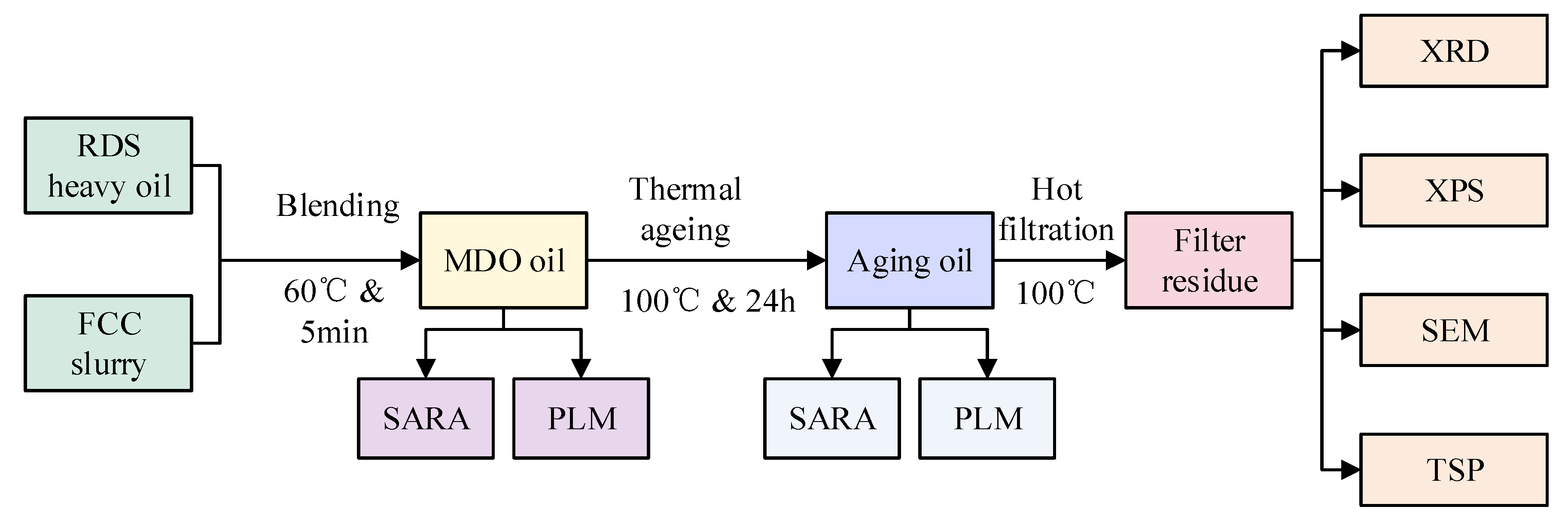
The experimental procedure was illustrated in Figure 1. Mixtures of RDS heavy oil and FCC slurry oil were prepared and thermally aged to assess their total sediment potential (TSP). The properties of these blends were detailed in Table 1. The primary precipitate component, asphaltenes, was characterized using scanning electron microscopy (SEM), X-ray photoelectron spectroscopy (XPS), and X-ray diffraction (XRD), Polarized Light Microscope (PLM).

2.2.1. Marine Fuel Blending and TSP Method

FCC slurry oil was blended with RDS heavy oil at mass fraction gradients of 5%, 10%, 15%, …, 50%, and the resulting blends were labeled as MDO-5, MDO-10, MDO-15, …, MDO-50. Each blend was stirred at 500 rpm for 5 min in a 60 °C constant-temperature oil bath to ensure homogeneity. Subsequently, the blended samples underwent thermal aging in accordance with the ISO 10307-2 standard [40]: samples were statically aged for 24 h at 100 °C under prescribed conditions to simulate long-term storage conditions for marine fuel oil.
After aging, the samples were vacuum filtered using double-layer GMF (Glass Microfiber Filter) paper in a 100 °C drying oven. The filter residue along with the filter paper was then transferred to a 100 °C air-blast drying oven for constant-weight drying for 30 min. Total sediment potential (TSP) for each test specimen was calculated using Equation (1) to obtain the S value:
S = ( m 5 m 4 ) ( m 3 m 2 ) 10 m 1 ,
where
S is the total sediment, expressed as percentage by mass;
m1 is the mass of the test portion, expressed in grams;
m2 is the mass of the lower filter before filtration, expressed in milligrams;
m3 is the mass of the lower filter after filtration, expressed in milligrams;
m4 is the mass of the upper filter before filtration, expressed in milligrams;
m5 is the mass of the upper filter after filtration, expressed in milligrams.

2.2.2. Property Analysis of Marine Fuel Oil

Density was measured according to ASTM D1298 [41] using a bitumen specific gravity bottle under constant temperature conditions (20.0 ± 0.1 °C). Kinematic viscosity was measured following the ASTM D445 standard [42] using a Cannon-Fenske reverse flow capillary viscometer at 50 °C. Four-component analysis was carried out using an IATROSCAN MK-6S (Tokyo, Japan), based on thin-layer chromatography (TLC). Saturates (Sat), aromatics (Aro), resins (Res), and asphaltenes (Asp) were separated on chromarods using different solvents and analyzed via hydrogen flame ionization detection. The area percentages of each component were calculated using the area normalization method.
Asphaltene extraction was conducted based on the ASTM 6560 [43] standard. A precipitation method using n-heptane was employed, where the oil was mixed with n-heptane at a 1:50 (v/v) ratio, stirred at 60 °C for 30 min, and then allowed to stand for 24 h to obtain precipitated asphaltenes. The resulting precipitate was sequentially filtered using 40 µm, 1.6 µm, and 0.22 µm filter membranes.

2.2.3. Characterization of Asphaltenes in Marine Fuel Oil

The macroscopic morphology of asphaltenes was observed using a polarized light microscope (Axiolab 5, Carl Zeiss, Oberkochen, Germany). The surface morphology of the asphaltene particulates was characterized using a scanning electron microscope (SEM, Hitachi High-Tech, Tokyo, Japan) operating at an accelerating voltage of 200 kV. Imaging was performed in secondary electron detection mode with working distances of 8–12 mm under high vacuum (<5 × 10⁻³ Pa). The crystalline structure of asphaltenes was characterized using an X-ray diffractometer (Ultima IV, Rigaku, Tokyo, Japan) with a scanning range of 2θ from 10° to 70°, a scan rate of 8°/min, and a wavelength (λ) of 1.5406 Å. The surface chemical states of asphaltenes were analyzed by X-ray photoelectron spectroscopy (XPS, ESCALAB 250XI, Thermo Fisher Scientific, Waltham, MA, USA) using high-resolution scans calibrated with C1s binding energy at 284.8 eV. Peak fitting for C1s, O1s, S2p, and N1s was performed using Origin 2024b software.

3. Results

3.1. Effect of FCC Slurry Oil on the Properties of Base Oils

3.1.1. Influence on Viscosity, Density, CCAI, and Sulfur Content

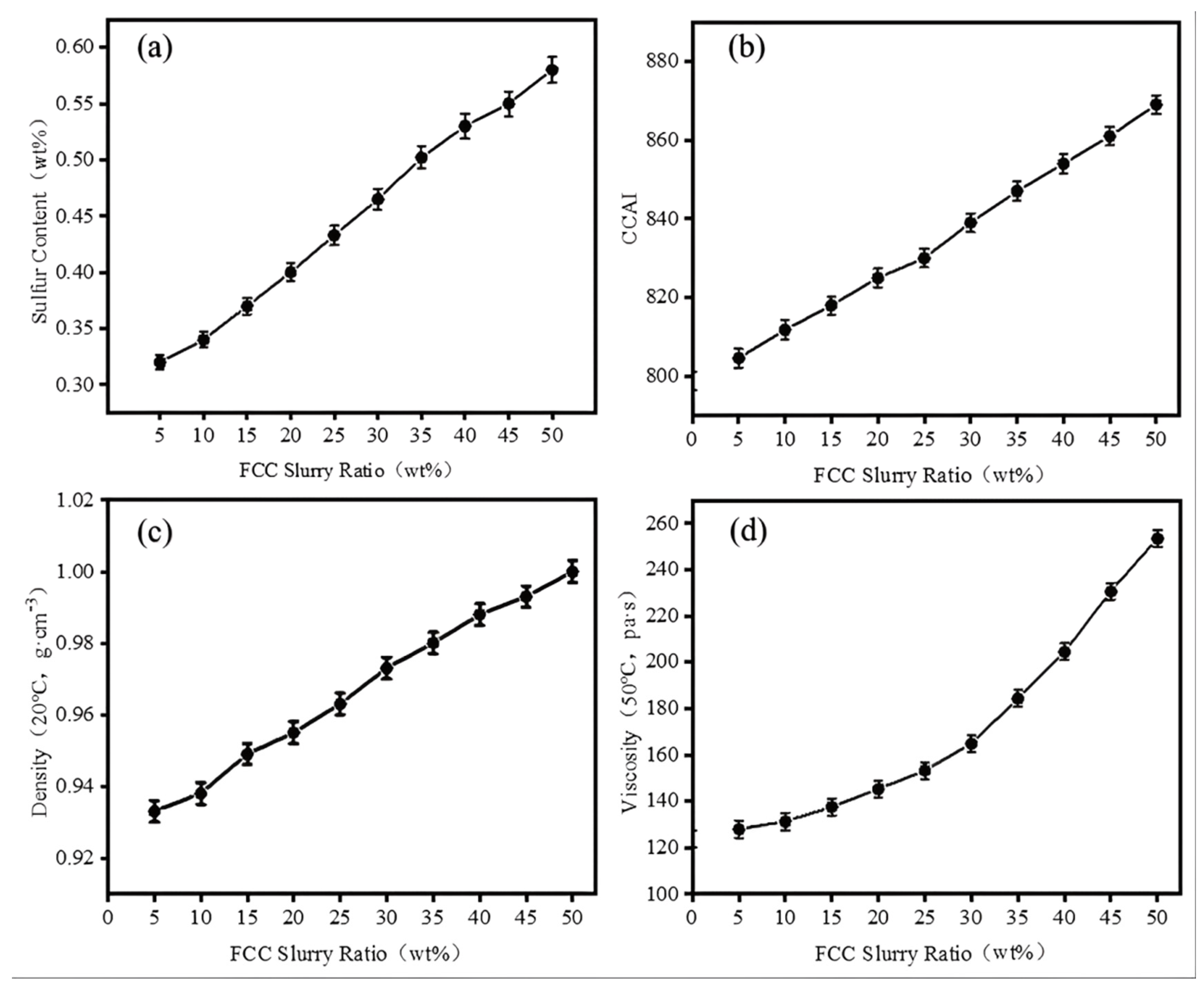
Based on the blended oils of RDS heavy oil and FCC slurry oil, significant changes were observed in the viscosity, density, CCAI (Calculated Carbon Aromaticity Index), and sulfur content of the blended oils as the proportion of FCC slurry oil increased. The results are shown in Figure 2.
As the FCC slurry oil blending ratio increases, the aromaticity, sulfur content, density, and viscosity of marine fuel oil also increase (Figure 2). While the incorporation of FCC slurry oil can reduce the blending cost of the oil, it also raises the risk of combustion carbon buildup, particulate emissions, and sulfur oxides (SOX) pollution due to the high sulfur content and solid particles present in the FCC slurry. According to the International Maritime Organization (IMO) 2020 sulfur cap regulation and ISO-8217-2024 technical specifications [44], the requirements for ISO-F-RMG 180H marine fuel oil are as follows: sulfur content ≤ 0.5% (by mass), CCAI ≤ 870, kinematic viscosity ≤ 180 mm2/s (at 50 °C), and density ≤ 991.0 kg/m3 (at 15 °C). When the FCC slurry oil blending ratio is below 30%, the blended fuel satisfies the ISO-F-RMG 180 [44] with sulfur content (0.46 wt%), CCAI (839), viscosity (164 mm2·s−1), and density (0.9731 g·cm−3).

3.1.2. Influence on TSP and SARA

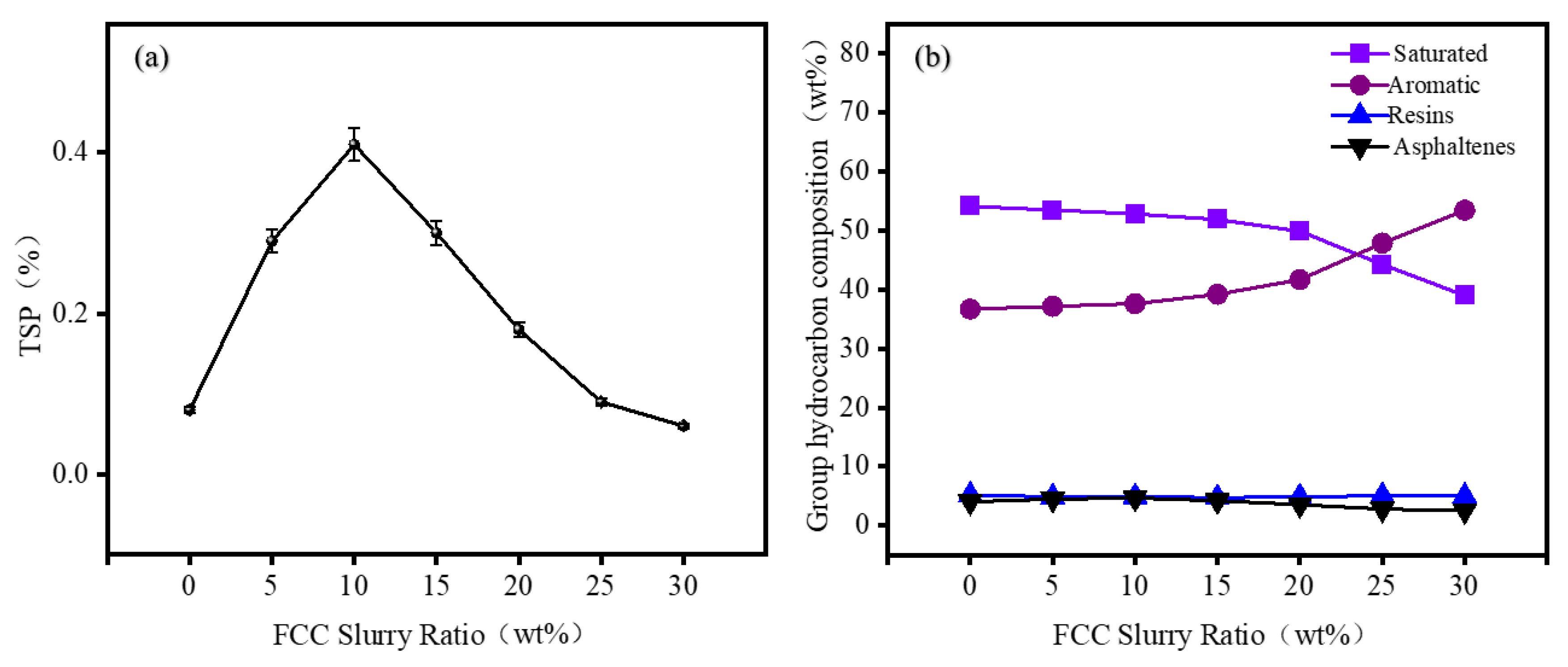
The stability of marine fuel oil was evaluated through standard procedures for aging, and the total sediment in residual fuel at different blending ratios was calculated based on Equation (1). A four-component analyzer was used to determine the variation in components in the blended fuels at different ratios, including saturates (Sat), aromatics (Aro), resins (Res), and asphaltenes (Asp). The results are shown in Figure 3.
The experimental results show that as the proportion of FCC slurry oil increases, the total sediment potential in the blended oils initially increases, reaching a maximum value of 0.41% at an FCC slurry oil of 10%. At this point, the TSP of the blended oil is at its highest, indicating that the inherent stability of the asphaltene system in the blend reaches a critical point. The high saturate content in RDS heavy oil disrupts the stable micellar structure of the asphaltene nuclei in the FCC slurry oil, significantly accelerating the asphaltene precipitation rate and leading to a peak in total precipitates. Further increasing the proportion of FCC slurry oil results in a significant reduction in TSP. When the proportion of FCC slurry oil reaches 25%, the TSP drops to 0.09%, meeting the standard requirement of 0.1%. This indicates that the high aromatic content in FCC slurry oil solubilizes the asphaltenes in the system, reducing the formation of total precipitates [45,46,47,48,49].
The SARA analysis data show that as the proportion of FCC slurry oil increases, the content of saturates gradually decreases, while the content of aromatics gradually increases. The changes in the content of resins and asphaltenes are relatively minor. FCC slurry oil has a high residual carbon and inherent asphaltene content. When FCC slurry oil is blended in small proportions, the total asphaltene content in the system increases. However, in a system dominated by the saturates of RDS heavy oil, asphaltenes tend to precipitate, which leads to an increase in the total precipitates. As the proportion of FCC slurry oil continues to rise, the proportion of aromatics in the system increases, and the asphaltenes are dispersed by the aromatics, thereby reducing the total precipitates.
The content of saturates and asphaltenes reflects the tendency of asphaltene association, while the content of aromatics and resins reflects their ability to disperse asphaltenes. Resins play a key role in preventing asphaltene deposition, and the ratio of resins to asphaltenes indicates the colloidal stability. The colloidal stability of the blended oils at different proportions was evaluated using the C.I.I value from Equation (2), along with the ω (Asp/Res), ω (Sat + Aro), and ω (Res + Asp) parameters. The results are shown in Figure 4.
C . I . I = ω   ( S a t + A s p ) ω   ( A r o + R e s )
The C.I.I value for FCC slurry oil is 0.28, while for RDS heavy oil, it is 1.38. As the proportion of FCC slurry oil increases, the C.I.I value gradually decreases, while the ω (Asp)/ω (Res) value first increases and then decreases, reaching a peak of 1.2 when the FCC slurry oil proportion is about 10%. At this point, the peptizing effect of resins on asphaltenes is at its lowest critical point. As the proportion of FCC slurry oil continues to increase, the ω (Asp)/ω (Res) value decreases (Figure 4a), enhancing the solubilizing ability of resins on asphaltenes. The trend of ω (Asp)/ω (Res) changes is consistent with the changes in total precipitates (Figure 3a). As the proportion of FCC slurry oil increases, the ω (Sat)/ω (Aro) value decreases, and the ω (Res + Asp) value first increases and then decreases, consistent with the changes in total precipitates (Figure 4b). When the FCC slurry oil proportion is 10%, the ω (Res + Asp) content reaches its maximum at 9.5%, and then decreases as the FCC slurry oil proportion increases.
The trend in ω (Asp)/ω (Res) is attributed to the formation of stable micellar structures through the interaction of polar groups in resins with asphaltenes. When the ratio of asphaltenes to resins increases, the system is in a sub-stable state, making asphaltenes more likely to detach from resin adsorption and aggregate. The trend in ω (Res + Asp) is influenced by the content of saturates and aromatics, reflecting the dispersion or precipitation of asphaltenes in the system. RDS heavy oil contains a high proportion of saturates and a lower proportion of aromatics, while FCC slurry oil has a high aromatic content and potential high asphaltene content. As FCC slurry oil is added, total precipitates initially increase because the high saturate content in RDS heavy oil precipitates asphaltenes from FCC slurry oil, increasing total precipitates. As the proportion of FCC slurry oil increases, the high aromatic content in FCC slurry oil solubilizes the asphaltenes, reducing total precipitates. The changes in (Res + Asp) and Asp/Res ratios are also consistent with the formation pattern of total precipitates [50].

3.1.3. Macroscopic Morphology of Asphaltenes in Blended Oils

Experimental data show that when the FCC slurry oil proportion reaches 10%, the TSP reaches its maximum, indicating the worst colloidal stability of the oil at this proportion. Based on this critical ratio, the oil sample with a 10:90 mixture of FCC slurry oil and RDS heavy oil, labeled as MDO-10, was selected for further study. The corresponding total precipitates were labeled as MDO-10-TSP. The morphological changes in the blended oil before and after aging and the infrared morphology of the total precipitates were observed using a polarized light microscope, and the formation mechanism of the precipitates was analyzed in depth, as shown in Figure 5.
The polarized light microscopy images in Figure 5 reveal significant morphological alterations of sediment within the oil phase of MDO-10 blended oils following thermal aging. Prior to thermal treatment (Figure 5a,b), the MDO-10 blended oil exhibited no observable precipitates. In contrast, post-aging analysis at identical magnification (Figure 5c) demonstrates the emergence of a dense, black reticular network structure. Higher magnification imaging (Figure 5d) further reveals that asphaltene micellar aggregates in the blended oil form a loosely organized three-dimensional reticular architecture distributed throughout the oil matrix, with aggregate dimensions spanning from tens to hundreds of micrometers. These structural transformations suggest that thermal aging conditions disrupt the dispersed phase through thermal energy input, consequently weakening interfacial interactions with asphaltenes. This destabilization mechanism promotes asphaltene dissociation from the dispersed phase, ultimately leading to aggregate formation [51,52]. Quantitative analysis of total sediment content following thermal aging revealed that the MDO-10-TSP produced a characteristic black filter cake (Figure 5e), containing 0.41 wt% sediment. Remarkably, asphaltenes constituted 83.49% of the sediment composition in MDO-10-TSP (Figure 5f), indicating that asphaltene aggregation represents the predominant mechanism driving excessive sediment formation in the blended oil system.
Property characterization of the base oil, MDO-10 blended oil, and total sediment (MDO-10-TSP) was performed, with the results summarized in Table 1.
Significant physicochemical and compositional distinctions were observed between RDS heavy oil and FCC slurry oil. The RDS feedstock demonstrates relatively low viscosity (129.31 mm2·s−1), high saturate content (56.28 wt%), low carbon residue (4.23 wt%), and low sulfur concentration (0.29 wt%). In contrast, FCC slurry oil exhibits substantially higher viscosity (525.2 mm2·s−1), predominant aromatic fraction (74.59 wt%), elevated carbon residue (7.12 wt%), and high sulfur content (0.82 wt%). The sediment mainly consists of asphaltenes, accounting for up to 83.49%. SARA analysis reveals RDS heavy oil is enriched in saturated hydrocarbons, while FCC slurry oil contains abundant aromatic hydrocarbons. Upon initial blending of FCC slurry oil, the TSP increased due to phase incompatibility, as the high saturate fraction in RDS heavy oil destabilized the asphaltenes in FCC slurry oil, leading to precipitation. However, as the FCC slurry oil blending ratio increased (>10%), this trend was reversed through a solubilization mechanism. The aromatic components in the FCC slurry oil facilitated the dispersion of asphaltenes, thereby reducing sediment formation. Mechanistic analysis reveals that sediment formation is governed by complex interactions among the four SARA fractions. Specifically, the combined effect of resins and asphaltenes (Res + Asp) and the Asp/Res ratio play a critical role in determining colloidal stability. This suggests that effective sediment control requires a careful balance between resin-mediated peptization and asphaltene self-association tendencies.
However, Table 1 also highlights a significant technical challenge associated with the use of FCC slurry oil: its elevated content of metals such as nickel (Ni), vanadium (V), iron (Fe), silicon (Si), and aluminum (Al). These metallic impurities, which become highly concentrated in the sediment (MDO-10-TSP), originate primarily from catalyst fines and metalloporphyrins present in the FCC feedstock. Although the aromatic components of FCC slurry oil enhance colloidal stability, metallic species can counteract this beneficial effect by promoting asphaltene aggregation [39], ultimately leading to excessive total sediment potential (TSP) in the blended fuel.

3.2. Asphaltene Structure and Morphology

To investigate the impact of asphaltene structural properties on the stability of the blended system, asphaltenes were extracted from RDS heavy oil, FCC slurry oil, and the highest sediment MDO-10 blended oil, named RDS-A, FCC-A, and MDO-10-A respectively. The structural and morphological changes in asphaltenes were studied to explore their influence on system stability.

3.2.1. SEM Analysis of Asphaltenes

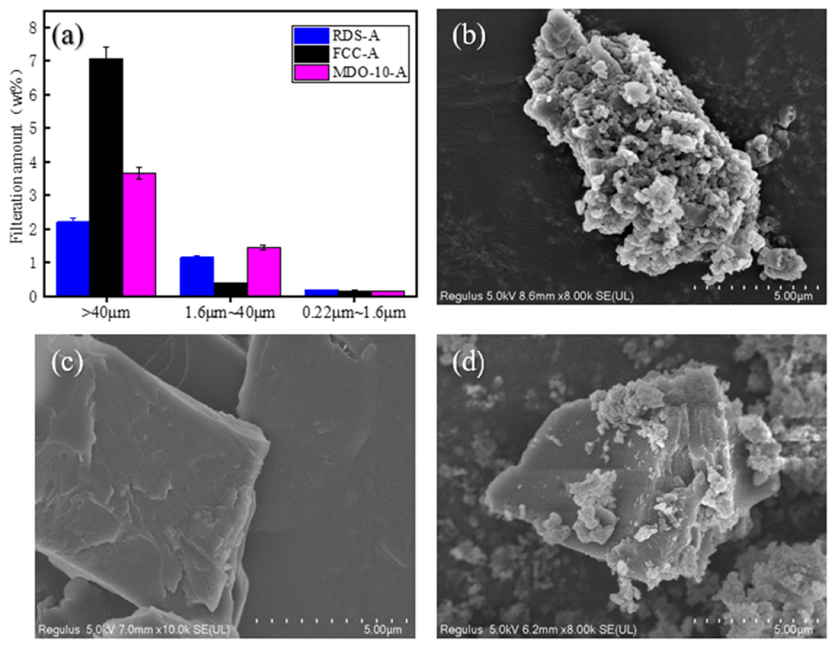
To characterize the particle size distribution and morphological features of asphaltenes from distinct oil sources, a sequential filtration protocol was implemented using graded membranes with pore sizes of 40 μm, 1.6 μm, and 0.22 μm. The fractionated asphaltene particulates were subsequently subjected to scanning electron microscopy (SEM) analysis. The results are shown in Figure 6.
The size distribution analysis (Figure 6a) reveals distinct asphaltene characteristics among different heavy oil samples. RDS-A demonstrates a relatively uniform asphaltene distribution, with only 2.21% of particles exceeding 40 μm, accompanied by 1.16% and 0.18% contents in the 40–1.6 μm and 1.6–0.22 μm ranges, respectively (Figure 6b). In contrast, FCC-A exhibits a significantly higher proportion (7.07%) of larger asphaltene particles (>40 μm) with reduced medium and small size fractions. SEM characterization (Figure 6c) identifies these FCC-A asphaltenes as lamellar-structured block aggregates, indicating strong aggregation tendencies [39]. MDO-10-A presents an intermediate size distribution between RDS-A and FCC-A systems. The composite microstructure, as evidenced by SEM (Figure 6d), features spherical RDS-A-derived asphaltenes embedded within the dominant FCC-A lamellar framework. This structural configuration, comprising 74.3% lamellar components and 25.7% spherical inclusions, strongly suggests FCC slurry oil asphaltenes as the primary source of MDO-10-A. The observed structural hierarchy and interfacial interactions between different asphaltene morphologies provide critical insights into aggregation mechanisms and colloidal stability, establishing a theoretical foundation for predicting sediment formation and optimizing oil product stability [16,53,54].

3.2.2. XRD Analysis of Asphaltenes

X-ray diffraction (XRD) analysis systematically characterizes the crystalline structure evolution of residual oil asphaltenes. The diffraction patterns exhibit four characteristic peaks: γ-crystalline peak, (002), (100), and (110) peaks (the latter typically undetectable due to low crystallinity). Key structural parameters derived from XRD include γ-crystalline layer spacing (dγ), aromatic interlayer spacing (dm), aromatic sheet diameter (La), cluster height (Lc), aromatic ring number per sheet (Ra), stacking layer number (Me), and aromatic carbon units (Cau) [55,56,57]. Analyzing the evolution of these structural parameters can reveal the aggregation behavior of asphaltene molecules during thermal aging and their intrinsic driving mechanisms. Comparative analysis of these parameters reveals fundamental structural differences between asphaltene types (Figure 7, Table 2).
Structural analysis demonstrates distinct characteristics between RDS-A and FCC-A asphaltenes. RDS-A exhibits larger dγ (7.64 Å) compared to FCC-A (5.46 Å), while its dm (3.51 Å) approaches graphite interlayer spacing (3.35 Å). This suggests compact aromatic stacking in RDS-A, potentially influenced by intercalated naphthenic structures restricting aromatic sheet expansion. MDO-10-A shows intermediate dγ (5.79 Å) and dm (3.62 Å) between the two systems.
The aromaticity index (fa) of RDS-A, FCC-A, and MDO-10-A are 0.15, 0.39, and 0.17, respectively. This suggests that MDO-10-A has a lower aromaticity, similar to RDS-A, whereas FCC-A forms dense layered structures through π-π stacking of polycyclic aromatic hydrocarbons (Figure 6c), resulting in high aromaticity [58]. RDS-A demonstrates significantly larger molecular dimensions (La = 240 Å, Lc = 266 Å, Cau = 371) than FCC-A (La = 197 Å, Lc = 102 Å, Cau = 304), indicating more extended aromatic clusters. Notably, MDO-10-A’s structural parameters closely match FCC slurry oil characteristics, while maintaining RDS-A-like aromaticity. This dual characteristic originates from spherical RDS-A asphaltenes (Figure 6d) embedded within FCC-A’s dominant lamellar framework, confirming MDO-10-A’s primary derivation from FCC slurry oil asphaltenes. These findings elucidate molecular-scale interaction mechanisms governing asphaltene aggregation, providing critical insights for predicting sedimentation behavior and optimizing oil stability [56,59].

3.2.3. XPS Analysis of Asphaltenes

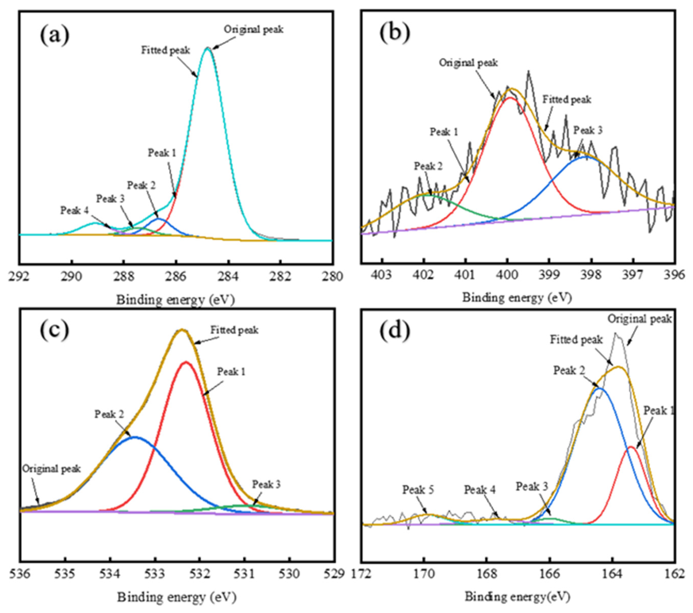
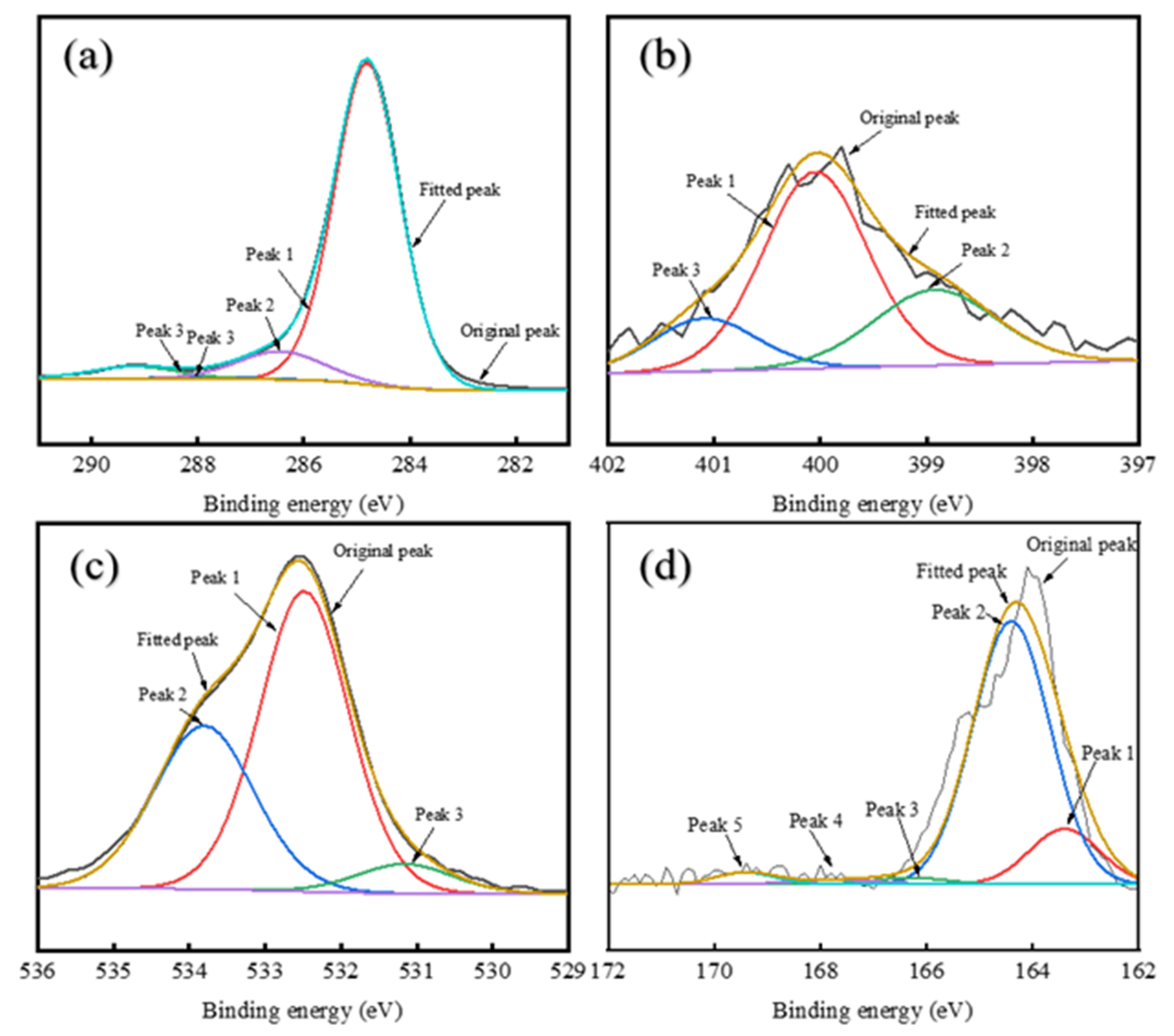
X-ray photoelectron spectroscopy (XPS) was used to analyze the chemical states of elements in the RDS-A, FCC-A, and MDO-10-A asphaltene samples, yielding spectra as shown in Figure 8, Figure 9 and Figure 10.
The XPS C 1s Spectrum of asphaltenes is divided into four components: C–H, C–C, C–O–C, C–OH, C–O, and COO– peaks [60,61]. Deconvolution of XPS C1s spectral analysis (Appendix A Table A1) reveals distinct compositional variations among the asphaltene samples. RDS-A exhibits a lower molar fraction of aliphatic C-H/C-C bonds (87.25%) compared to FCC-A (92.31%), indicating reduced aromaticity (fa) in RDS-A. This structural difference for RDS-A originates from hydrogen saturation during hydrodesulfurization, which diminishes aromatic ring content by converting polyaromatic structures into saturated hydrocarbons. In contrast, MDO-10-A exhibits transitional characteristics in its structural parameters, with aromaticity between those of RDS-A and FCC-A. In contrast, MDO-10-A demonstrates intermediate aromaticity, aligning with its transitional structural characteristics observed in SEM and XRD analyses (Figure 6d and Table 2). The consistent multi-correlation underscores the critical role of asphaltene molecular architecture in governing colloidal stability within blended oil systems.
Based on the XPS N 1s Spectral Analysis (Appendix A Table A2), there is a remarkable nitrogen speciation homology between RDS-A and MDO-10-A systems. RDS-A exhibits predominant pyrrolic nitrogen (58.15%), with secondary pyridinic (26.23%) and quaternary nitrogen (15.62%) contributions, consistent with typical hydrodesulfurized residue characteristics [62]. FCC-A shows undetectable nitrogen content (<0.1 at%), confirming its catalytic cracking origin. Strikingly, MDO-10-A replicates RDS-A’s nitrogen fingerprint with predominant pyrrolic nitrogen (54.89%), establishing RDS-A as the principal nitrogen source.
Deconvolution of the XPS O1s spectra (Appendix A Table A3) resolves three oxygen-containing functional groups: carbonyl (C=O,), C-O single bonds (C-OH), and carboxylates (COO) [16]. RDS-A exhibits balanced oxygen speciation with dominant C-O bonds (54.67%) and substantial carboxylates (40.82%), contrasting sharply with FCC-A’s overwhelming C-O dominance (89.19%), indicative of phenolic-rich structures from catalytic cracking. MDO-10-A replicates RDS-A’s oxygen profile with C-O single bonds (58.35%) and carboxylates (35.57%), confirming that the oxygen in MDO-10-A primarily originates from RDS heavy oil asphaltenes.
The sulfur-containing functional groups in XPS S2p spectral analysis (Appendix A Table A4) can be divided into peaks representing alkyl sulfides, thiophenes, sulfoxides, sulfones, sulfonic acids, and sulfates [62,63]. RDS-A exhibits dominant thiophenic sulfur (68.63%) with minor alkyl sulfides (23.26%), characteristic of hydrodesulfurized residue oils. In FCC-A, the sulfur content is also low, with no significant peak signals detected. Remarkably, MDO-10-A replicates RDS-A’s sulfur fingerprint (thiophenes: 71.66%; alkyl sulfides:23.01%), which are highly matching with RDS-A. This further confirms that the sulfur in MDO-10-A primarily originates from RDS heavy oil asphaltenes.

3.3. Mechanism of Asphaltene Aggregation

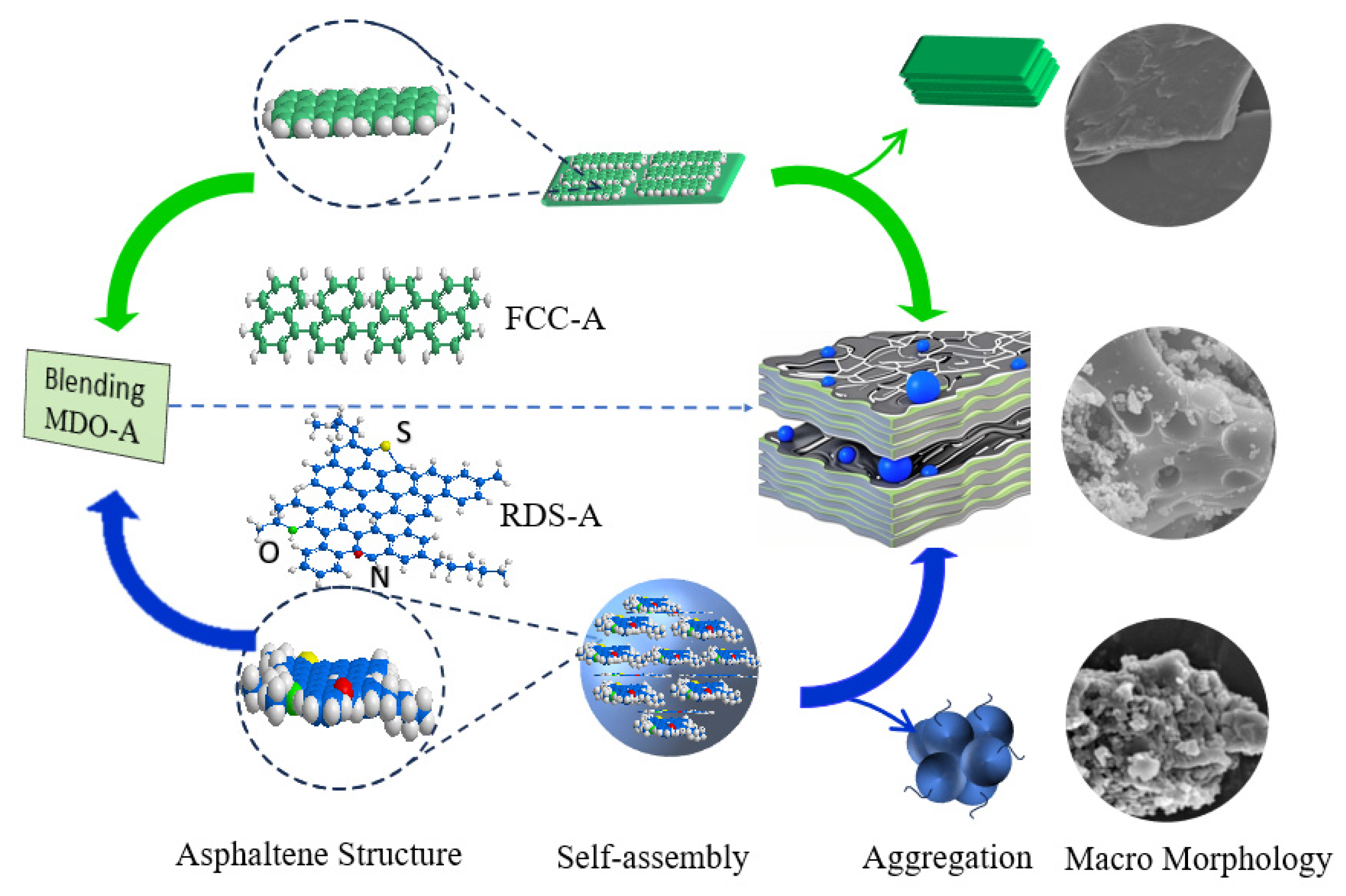
Figure 11 illustrates the structural evolution and aggregation behavior of asphaltenes during the blending process of FCC slurry oil and RDS heavy oil. FCC-A, characterized by smaller molecular dimensions and higher aromaticity, undergoes lamellar stacking via π-π interactions between condensed polyaromatic sheets, resulting in planar aggregates. In contrast, RDS-A, with larger molecular dimensions and heteroatom-rich polar groups, exhibits spherical aggregation driven by synergistic π-π and dipole–dipole interactions.
When a small amount of FCC slurry oil is blended, the high saturate content in RDS heavy oil destabilizes the asphaltenes in the FCC slurry oil, promoting aggregation through π-π interactions. Simultaneously, heteroatoms such as sulfur, nitrogen, and oxygen significantly influence the solubility and aggregation behavior of asphaltenes by enhancing dipole–dipole interactions and hydrogen bonding. The heteroatom content in RDS-A contributes to the formation of a more complex and diverse aggregation structure. The polar interactions introduced by heteroatoms mediate the embedding of spherical RDS-A within the planar FCC-A aggregates, impacting the overall colloidal stability of the blend.
This aggregation mechanism underscores the critical role of balancing aromatic and saturated hydrocarbons, ensuring structural compatibility of asphaltenes, and accounting for the presence of heteroatoms, which is essential for optimizing blending strategies and ensuring the production of stable, compliant marine fuels.

4. Conclusions

This study demonstrates that the blending ratio of FCC slurry oil plays a critical role in the colloidal stability of low-sulfur marine fuels. Specifically, it highlights the instability issues associated with blending excessively hydrotreated RDS heavy oil, which is produced in the residue hydrotreating units of full-conversion refineries. Total Sediment Potential (TSP) shows a non-monotonic response to FCC addition. Initially, TSP increases, peaking at 0.41% when the FCC ratio reaches 10%, due to destabilization of FCC-derived asphaltenes by high-saturation hydrocarbons in RDS heavy oil. Increasing the FCC ratio to 25% reduces TSP to 0.09%, attributed to the solubilizing effect of aromatic fractions on asphaltenes.
SARA analysis demonstrated that the ω (Asp/Res) ratio and ω (Asp + Res) show consistent trends with TSP, reaching a maximum at 10% FCC incorporation, indicating weakened peptization capacity of resins. Beyond this threshold, the enhanced aromatic content of FCC slurry oil improved colloidal stability by suppressing asphaltene aggregation.
XRD and SEM analyses showed distinct structural differences between RDS-derived and FCC-derived asphaltenes. FCC-A had smaller molecular dimensions and higher aromaticity, forming planar aggregates, while RDS-A were larger and heteroatom-rich, leading to spherical aggregation. MDO-A exhibited FCC-dominated sediment architecture, with spherical RDS-A particles embedded in FCC-A matrices, confirming FCC asphaltenes as the primary sediment precursors. XPS confirmed that heteroatoms (N, S, O) in MDO-A asphaltenes were mainly derived from RDS-A.
This study delves into the compatibility between RDS heavy oil and FCC slurry oil—a binary system critical to industrial fuel formulation yet often overlooked. Our results reveal that marine fuel stability depends fundamentally on the balance between saturate and aromatic components. The non-monotonic variation in TSP with FCC slurry oil ratio, correlated with asphaltene structural changes, delivers practical guidance for optimizing blends to minimize sedimentation. This insight facilitates the production of stable low-sulfur marine fuels and improves operational flexibility for refineries employing deeply hydrotreated residues.
Author Contributions

Conceptualization, S.G. and J.D.; methodology, H.C.; software, L.C.; validation, Q.F., and L.Z.; formal analysis, A.L.; investigation, R.J. and J.W.; resources, S.G.; data curation, J.T.; writing—original draft preparation, A.L.; writing—review and editing, Q.F.; visualization, L.Z.; supervision, Q.F.; project administration, L.Z.; funding acquisition, Q.F. All authors have read and agreed to the published version of the manuscript.

Funding

This research was funded by National Natural Science Foundation of China, grant number 22368051 and The work was funded by Projects of Talents Recruitment of GDUPT (2019rc013, 2023rcyj2005). This work was also financially supported by the Science and Technology project of SINOPEC Zhongke (Guangdong) Refinery & Petrochemical Company Limited, (34860000-24-ZC0607-0014).

Data Availability Statement

The original contributions presented in this study are included in the article. Further inquiries can be directed to the corresponding authors.

Acknowledgments

The authors thank SINOPEC Zhongke (Guangdong) Refinery & Petrochemical Company Limited for enabling the laboratory experiments. The investigations were carried out using the equipment of the Oil Quality Testing Center. We are particularly grateful to Jinru Guo from the Center for her invaluable technical assistance and support.

Conflicts of Interest

Two of the authors, Shengjun Guo and Jianwen Deng, were employed by the company SINOPEC Zhongke (Guangdong) Refinery & Petrochemical Company Limited. The remaining authors declare that the research was conducted in the absence of any commercial or financial relationships that could be construed as a potential conflict of interest.

Abbreviations

IMOInternational Maritime Organization
TSPTotal sediment potential
FCCFluid catalytic cracking
RDSResidue desulfurization
CCAICalculated Carbon Aromaticity Index

Appendix A

Table A1. Fitting data of XPS C 1s spectra in the asphaltenes.
ProductPeakBinding Energy/eVCarbon FormAtomic Ratio (%)
RDS-A1284.8C–H, C–C87.25
2286.7C-O-C, C–OH, C–O5.37
3287.5C=O2.69
4289.1COO-4.69
FCC-A1284.8C–H, C–C92.31
2286.5C-O-C, C–OH, C–O4.01
3287.3C=O1.77
4288.4COO-1.91
MDO-A1284.8C–H, C–C89.14
2286.5C-O-C, C–OH, C–O4.84
3287.7C=O2.46
4289.2COO-3.56
Table A2. Fitting data of XPS N 1s spectra in the asphaltenes.
ProductPeakBinding Energy/eVCarbon FormAtomic Ratio (%)
RDS-A1398.7Pyridinic-N30.74
2399.9Pyrrolic-N51.42
3402Quaternary-N17.84
FCC-A1 Pyridinic-N
2 Pyrrolic-N
3 Quaternary-N
MDO-A1398.9Pyridinic-N26.23
2400Pyrrolic-N58.15
3401.1Quaternary-N15.63
Table A3. Fitting data of XPS O 1s spectra in the asphaltenes.
ProductPeakBinding Energy/eVCarbon FormAtomic Ratio (%)
RDS-A1531C=O4.51
2532.3C–O–C, C–OH, C–O54.67
3533.5COO-40.82
FCC-A1531C=O3.27
2532.5C–O–C, C–OH, C–O89.19
3533.8COO-7.53
MDO-A1531.2C=O6.09
2532.5C–O–C, C–OH, C–O58.35
3533.8COO-35.57
Table A4. Fitting data of XPS S 2p spectra in the asphaltenes.
ProductPeakBinding Energy/eVSulphides FormAtomic Ratio (%)
RDS-A1163.4Alkyl sulphides23.26
2164.4Thiophenes68.63
3166.0Sulphoxides1.78
4167.7Sulphones2.76
5169.9Sulphonic acids and sulphates3.57
FCC-A1 Alkyl sulphides
2 Thiophenes
3 Sulphoxides
4 Sulphones
5 Sulphonic acids and sulphates
MDO-A1163.4Alkyl sulphides23
2164.4Thiophenes71.67
3166.3Sulphoxides1.63
4167.7Sulphonic1.27
5169.4Sulphonic acids and sulphates2.43

References

  1. Moreira, C.A.B.; Polezer, G.; Silva, J.C.d.S.; Zorzenão, P.C.d.S.; Godoi, A.F.L.; Huergo, L.F.; Yamamoto, C.I.; Tadano, Y.d.S.; Potgieter-Vermaak, S.; Reis, R.A.; et al. Impact assessment of IMO’s sulfur content limits: A case study at latin America’s largest grain port. Air Qual. Atmos. Health 2024, 17, 2337–2351. [Google Scholar] [CrossRef]
  2. Müller-Casseres, E.; Leblanc, F.; van den Berg, M.; Fragkos, P.; Dessens, O.; Naghash, H.; Draeger, R.; Gallic, T.L.; Tagomori, I.S.; Tsiropoulos, I.; et al. Managing the risks against carbon neutralization for green maritime transport. J. Clean. Prod. 2024, 457, 142478. [Google Scholar] [CrossRef]
  3. Kim, H.; Lee, S.; Lee, J.; Kim, D. A Data-Driven Approach to Analyzing Fuel-Switching Behavior and Predictive Modeling of Liquefied Natural Gas and Low Sulfur Fuel Oil Consumption in Dual-Fuel Vessels. J. Mar. Sci. Eng. 2024, 12, 2235. [Google Scholar] [CrossRef]
  4. Ershov, M.A.; Savelenko, V.D.; Makhmudova, A.E.; Rekhletskaya, E.S.; Makhova, U.A.; Kapustin, V.M.; Mukhina, D.Y.; Abdellatief, T.M.M. Technological Potential Analysis and Vacant Technology Forecasting in Properties and Composition of Low-Sulfur Marine Fuel Oil (VLSFO and ULSFO) Bunkered in Key World Ports. J. Mar. Sci. Eng. 2022, 10, 1828. [Google Scholar] [CrossRef]
  5. Halff, A.; Younes, L.; Boersma, T. The likely implications of the new IMO standards on the shipping industry. Energy Policy 2019, 126, 277–286. [Google Scholar] [CrossRef]
  6. Van, T.C.; Ramirez, J.; Rainey, T.; Ristovski, Z.; Brown, R.J. Global impacts of recent IMO regulations on marine fuel oil refining processes and ship emissions. Transport. Res. D Transp. Environ. 2019, 70, 123–134. [Google Scholar] [CrossRef]
  7. Asghari, M.; Afshari, H.; Jaber, M.Y.; Searcy, C. Strategic analysis of hydrogen market dynamics across collaboration models. Renew. Sust. Energy Rev. 2025, 208, 115001. [Google Scholar] [CrossRef]
  8. Atnoorkar, S.; Zhang, K.; Kraft, K.; Lewis, K.C.; Newes, E.; Camenzind, D.; Peterson, S. Future marine biofuels in the port of Seattle region. Front. Energy Res. 2025, 13, 1550093. [Google Scholar] [CrossRef]
  9. Rastogi, P.; Kaisare, N.S.; Basavaraj, M.G. Emulsions as viable alternative to conventional fuels: Current status and challenges. Langmuir 2024, 40, 2800–2808. [Google Scholar] [CrossRef]
  10. Panoutsou, C.; Germer, S.; Karka, P.; Papadokostantakis, S.; Kroyan, Y.; Wojcieszyk, M.; Maniatis, K.; Marchand, P.; Landalv, I. Advanced biofuels to decarbonise European transport by 2030: Markets, challenges, and policies that impact their successful market uptake. Energy Strategy Rev. 2021, 34, 100633. [Google Scholar] [CrossRef]
  11. Shen, F.; Li, X. Effects of fuel types and fuel sulfur content on the characteristics of particulate emissions in marine low-speed diesel engine. Environ. Sci. Pollut. Res. 2020, 27, 37229–37236. [Google Scholar] [CrossRef]
  12. Aymelek, M.; Boulougouris, E.; Turan, O.; Konovessis, D. Challenges and opportunities for LNG as a ship fuel source and an application to bunkering network optimisation. In Maritime Technology and Engineering; CRC Press: Boca Raton, FL, USA, 2014; pp. 767–776. [Google Scholar]
  13. Bilgili, L. Life cycle comparison of marine fuels for IMO 2020 Sulphur Cap. Sci. Total Environ. 2021, 774, 145719. [Google Scholar] [CrossRef] [PubMed]
  14. Hazrat, M.; Rasul, M.; Khan, M.; Mofijur, M.; Ahmed, S.; Ong, H.C.; Vo, D.-V.N.; Show, P.L. Techniques to improve the stability of biodiesel: A review. Environ. Chem. Lett. 2021, 19, 2209–2236. [Google Scholar] [CrossRef]
  15. Vedachalam, S.; Baquerizo, N.; Dalai, A.K. Review on impacts of low sulfur regulations on marine fuels and compliance options. Fuel 2022, 310, 122243. [Google Scholar] [CrossRef]
  16. Smyshlyaeva, K.I.; Rudko, V.A.; Kuzmin, K.A.; Povarov, V.G. Asphaltene genesis influence on the low-sulfur residual marine fuel sedimentation stability. Fuel 2022, 328, 125291. [Google Scholar] [CrossRef]
  17. Povarov, V.G.; Efimov, I.; Smyshlyaeva, K.I.; Rudko, V.A. Application of the UNIFAC Model for the Low-Sulfur Residue Marine Fuel Asphaltenes Solubility Calculation. J. Mar. Sci. Eng. 2022, 10, 1017. [Google Scholar] [CrossRef]
  18. Kondrasheva, N.K.; Rudko, V.A.; Kondrashev, D.O.; Shakleina, V.S.; Smyshlyaeva, K.I.; Konoplin, R.R.; Shaidulina, A.A.; Ivkin, A.S.; Derkunskii, I.O.; Dubovikov, O.A. Application of a ternary phase diagram to describe the stability of residual marine fuel. Energy Fuels 2019, 33, 4671–4675. [Google Scholar] [CrossRef]
  19. Kass, M.D.; Armstrong, B.L.; Kaul, B.C.; Connatser, R.M.; Lewis, S.; Keiser, J.R.; Jun, J.; Warrington, G.; Sulejmanovic, D. Stability, combustion, and compatibility of high-viscosity heavy fuel oil blends with a fast pyrolysis bio-oil. Energy Fuels 2020, 34, 8403–8413. [Google Scholar] [CrossRef]
  20. Kim, J.-S.; Choi, J.-H. Feasibility study on bio-heavy fuel as an alternative for marine fuel. Renew. Energy 2023, 219, 119543. [Google Scholar] [CrossRef]
  21. Mukherjee, A.; Bruijnincx, P.; Junginger, M. Techno-economic competitiveness of renewable fuel alternatives in the marine sector. Renew. Sustain. Energy Rev. 2023, 174, 113127. [Google Scholar] [CrossRef]
  22. Xu, M.; Zhu, Y.; Du, C.; Liu, J.; Wang, C.; Na, Z.; Shang, J.; Li, D. Multi-scale analysis on the aggregation mechanism of oxygen-rich coal-derived asphaltene molecules. J. Mol. Liq. 2023, 387, 122640. [Google Scholar] [CrossRef]
  23. Rogel, E.; Moir, M.E.; Hurt, M.; Miao, T.; Lee, E. Asphaltene and maltene adsorption into graphene. Energy Fuels 2019, 33, 9538–9545. [Google Scholar] [CrossRef]
  24. Hemmati-Sarapardeh, A.; Ameli, F.; Ahmadi, M.; Dabir, B.; Mohammadi, A.H.; Esfahanizadeh, L. Effect of asphaltene structure on its aggregation behavior in toluene-normal alkane mixtures. J. Mol. Struct. 2020, 1220, 128605. [Google Scholar] [CrossRef]
  25. Pinheiro, I.F.; Bizarre, L.; Perles, C.E.; Feitosa, F.X.; de Sant’Ana, H.B.; Rosa, P.d.T.V.; van der Geest, C.; Guersoni, V.C. Exploring asphaltene aggregation: Model systems based on toluene-heptane mixtures. Fuel 2020, 372, 132152. [Google Scholar] [CrossRef]
  26. Huang, Y.; Wu, Z.; Liang, L.; Ying, J.; Gui, L.; Shen, P.K.; Tian, Z.Q. Revealing the dependance of mechanical properties of asphalt binder on graphene size via multi-scale methods. Mater. Des. 2023, 236, 112478. [Google Scholar] [CrossRef]
  27. Murgich, J.; Merino-Garcia, D.; Andersen, S.I.; del Río, J.M.; Galeana, C.L. Molecular mechanics and microcalorimetric investigations of the effects of molecular water on the aggregation of asphaltenes in solutions. Langmuir 2002, 18, 9080–9086. [Google Scholar] [CrossRef]
  28. Wang, Z.; Hu, J.; Shui, H.; Ren, S.; Wei, C.; Pan, C.; Lei, Z.; Cui, X. Study on the structure and association of asphaltene derived from liquefaction of lignite by fluorescence spectroscopy. Fuel 2013, 109, 94–100. [Google Scholar] [CrossRef]
  29. Wang, L.; Hu, Y.; Wang, L.; Zhu, Y.; Zhang, H.; Huang, Z.; Yuan, P. Visbreaking of heavy oil with high metal and asphaltene content. J. Anal. Appl. Pyrolysis 2021, 159, 105336. [Google Scholar] [CrossRef]
  30. Ding, Y.; Deng, M.; Cao, X.; Yu, M.; Tang, B. Investigation of mixing effect and molecular aggregation between virgin and aged asphalt. Constr. Build. Mater. 2019, 221, 301–307. [Google Scholar] [CrossRef]
  31. Dechaine, G.P.; Gray, M.R. Chemistry and association of vanadium compounds in heavy oil and bitumen, and implications for their selective removal. Energy Fuels 2010, 24, 2795–2808. [Google Scholar] [CrossRef]
  32. Efimov, I.; Smyshlyaeva, K.I.; Povarov, V.G.; Buzyreva, E.D.; Zhitkov, N.V.; Vovk, M.A.; Rudko, V.A. UNIFAC residual marine fuels stability prediction from NMR and elemental analysis of SARA components. Fuel 2023, 352, 129014. [Google Scholar] [CrossRef]
  33. Kuzmin, K.A.; Sultanbekov, R.R.; Khromova, S.M.; Vovk, M.A.; Rudko, V.A. Establishing the influence of recycled used oil on the sedimentation stability of residual marine fuel. Fuel 2025, 389, 134625. [Google Scholar] [CrossRef]
  34. Zvereva, A.E.; Ershov, M.A.; Savelenko, V.D.; Lobashova, M.M.; Rogova, M.Y.; Makhova, U.A.; Tikhomirova, E.O.; Burov, N.O.; Aleksanyan, D.R.; Kapustin, V.M.; et al. Use of asphaltene stabilizers for the production of very low sulphur fuel oil. Energies 2023, 16, 7649. [Google Scholar] [CrossRef]
  35. Osei, F.B.; Twum, K.; Surapaneni, S.; Surur, A.; Fatohi, M.; Beyeh, N.K. A resorcinarene-based crude oil asphaltene dispersant. Fuel 2024, 375, 132428. [Google Scholar] [CrossRef]
  36. Marafi, A.; Hauser, A.; Stanislaus, A. Atmospheric residue desulfurization process for residual oil upgrading: An investigation of the effect of catalyst type and operating severity on product oil quality. Energy Fuels 2006, 20, 1145–1149. [Google Scholar] [CrossRef]
  37. Pham, D.D.; Nguyen, T.M.; Ho, T.H.; Le, Q.V.; Nguyen, D.L. Advancing hydrodesulfurization in heavy Oil: Recent developments, challenges, and future prospects. Fuel 2024, 372, 132082. [Google Scholar] [CrossRef]
  38. Jarullah, A.T.; Mujtaba, I.M.; Wood, A.S. Improving fuel quality by whole crude oil hydrotreating: A kinetic model for hy-drodeasphaltenization in a trickle bed reactor. Appl. Energy 2012, 94, 182–191. [Google Scholar] [CrossRef]
  39. Ma, Y.; Deng, W.; Li, G.; Ullah, S.; Zhang, Z.; Chen, L.; Zhou, X. Structural and Electrochemical Enhancement of FCC Slurry Oil-Derived Pitch via Asphaltene-Driven Graphitic Ordering. ACS Omega 2025, 10, 21823–21834. [Google Scholar] [CrossRef] [PubMed]
  40. ISO 10307-2; Petroleum Products—Total Sediment in Residual Fuel Oils—Part 2: Determination Using Standard Procedures for Ageing. International Organization for Standardization: Geneva, Switzerland, 2009.
  41. ASTM D1298; Standard Test Method for Density, Relative Density, or API Gravity of Crude Petroleum and Liquid Petroleum Products by Hydrometer Method. ASTM International: West Conshohocken, PA, USA, 2024.
  42. ASTM D445; Standard Test Method for Kinematic Viscosity of Transparent and Opaque Liquids (and Calculation of Dynamic Viscosity). ASTM International: West Conshohocken, PA, USA, 2024.
  43. ASTM D6560; Standard Test Method for Determination of Bromine Number of Petroleum Distillates and Commercial Aliphatic Olefins by Electrometric Titration. ASTM International: West Conshohocken, PA, USA, 2024.
  44. ISO 8217; Petroleum Products—Fuels (Class F)—Specifications of Marine Fuels. International Organization for Standardization: Geneva, Switzerland, 2024.
  45. Santos, D.; Amaral, M.; Elvio Filho, B.; Dourado, R.S.; Coutinho, J.A.; Borges, G.R.; Franceschi, E.; Dariva, C. Revisiting the methodology for asphaltenes precipitation. J. Pet. Sci. Eng. 2019, 178, 778–786. [Google Scholar] [CrossRef]
  46. Lu, X.; Soenen, H.; Sjövall, P.; Pipintakos, G. Analysis of asphaltenes and maltenes before and after long-term aging of bitumen. Fuel 2021, 304, 121426. [Google Scholar] [CrossRef]
  47. Li, J.; Wang, X.; Tang, X.; Wang, F.; Qing, D. Effect of Transition Metal Polymers with Varying Side Alkyl Chain on Viscosity Reduction of Crude Oil and Aggregation Behavior of Asphaltene. Energy Fuels 2015, 29, 7771–7780. [Google Scholar] [CrossRef]
  48. Xu, H.; Zou, Y.; Airey, G.; Wang, H.; Zhang, H.; Wu, S. Wetting of bio-rejuvenator nanodroplets on bitumen: A molecular dy-namics investigation. J. Clean. Prod. 2024, 444, 141140. [Google Scholar] [CrossRef]
  49. Mullins, O.C.; Sabbah, H.; Eyssautier, J.; Pomerantz, A.E.; Barré, L. Advances in asphaltene science and the Yen–Mullins model. Energy Fuels 2012, 26, 3986–4003. [Google Scholar] [CrossRef]
  50. Liu, Y.; Zou, Y. Effects of aromatic cycle oils on performance of residue hydrotreating. Korean J. Chem. Eng. 2013, 30, 1985–1989. [Google Scholar] [CrossRef]
  51. Zaluzec, N.J.; Janssen, A.; Kulzick, M.A.; Burke, M. In situ Analytical Microscopy of Asphaltene Aggregation and Growth. Microsc. Microanal. 2017, 23, 932–933. [Google Scholar] [CrossRef]
  52. Balestrin, L.B.d.S.; Cardoso, M.B.; Loh, W. Using atomic force microscopy to detect asphaltene colloidal particles in crude oils. Energy Fuels 2017, 31, 3738–3746. [Google Scholar] [CrossRef]
  53. Gesho, M.; Chaisoontornyotin, W.; Elkhatib, O.; Goual, L. Auto-segmentation technique for SEM images using machine learning: Asphaltene deposition case study. Ultramicroscopy 2020, 217, 113074. [Google Scholar] [CrossRef] [PubMed]
  54. AlHumaidan, F.S.; Rana, M.S.; Tanoli, N.J.; Lababidi, H.M.; Al-Najdi, N.A. Changes in asphaltene surface topography with thermal treatment. Arab. J. Chem. 2020, 13, 5377–5389. [Google Scholar] [CrossRef]
  55. Nguyen, N.T.; Kang, K.H.; Lee, C.W.; Kim, G.T.; Park, S.; Park, Y.-K. Structure comparison of asphaltene aggregates from hy-drothermal and catalytic hydrothermal cracking of C5-isolated asphaltene. Fuel 2019, 235, 677–686. [Google Scholar] [CrossRef]
  56. AlHumaidan, F.S.; Hauser, A.; Rana, M.S.; Lababidi, H.M.; Behbehani, M. Changes in asphaltene structure during thermal cracking of residual oils: XRD study. Fuel 2015, 150, 558–564. [Google Scholar] [CrossRef]
  57. Gebresellasie, K.; Lewis, J.; Shirokoff, J. X-ray spectral line shape analysis of asphalt binders. Energy Fuels 2013, 27, 2018–2024. [Google Scholar] [CrossRef]
  58. Sadeghtabaghi, Z.; Rabbani, A.R.; Hemmati-Sarapardeh, A. A review on asphaltenes characterization by X-ray diffraction: Fundamentals, challenges, and tips. J. Mol. Struct. 2021, 1238, 130425. [Google Scholar] [CrossRef]
  59. Bansal, V.; Patel, M.; Sarpal, A. Structural aspects of crude oil derived asphaltenes by NMR and XRD and spectroscopic tech-niques. Pet. Sci. Technol. 2004, 22, 1401–1426. [Google Scholar] [CrossRef]
  60. Larachi, F.; Dehkissia, S.; Adnot, A.; Chornet, E. X-ray Photoelectron Spectroscopy, Photoelectron Energy Loss Spectroscopy, X-ray Excited Auger Electron Spectroscopy, and Time-of-Flight− Secondary Ion Mass Spectroscopy Studies of Asphaltenes from Doba− Chad Heavy Crude Hydrovisbreaking. Energy Fuels 2004, 18, 1744–1756. [Google Scholar] [CrossRef]
  61. Geng, W.; Kumabe, Y.; Nakajima, T.; Takanashi, H.; Ohki, A. Analysis of hydrothermally-treated and weathered coals by X-ray photoelectron spectroscopy (XPS). Fuel 2009, 88, 644–649. [Google Scholar] [CrossRef]
  62. Sun, Z.; Li, D.; Ma, H.; Tian, P. Characterization of asphaltene isolated from low-temperature coal tar. Fuel Process. Technol. 2015, 138, 413–418. [Google Scholar] [CrossRef]
  63. Kozłowski, M. XPS study of reductively and non-reductively modified coals. Fuel 2024, 83, 259–265. [Google Scholar] [CrossRef]
Figure 1. Schematic diagram of the experimental procedure.
Jmse 13 01713 g001
Figure 2. The effect of FCC slurry oil blending ratio on marine fuel oil properties: (a) sulfur content; (b) CCAI; (c) density; and (d) viscosity.
Jmse 13 01713 g002
Figure 3. The effect of FCC slurry oil on the TSP and SARA of the blended fuel: (a) TSP; (b) SARA.
Jmse 13 01713 g003
Figure 4. Correlation diagrams of four-component compositions: (a) Sat/Aro value vs. Asp/Res; (b) C.I.I vs. ω (Res + Aro).
Jmse 13 01713 g004
Figure 5. Polarized Light Microscopy Analysis of MDO-10 Blended Oils and MDO-10-TSP: (a) MDO-10 before thermal aging observed with a 5× objective lens; (b) MDO-10 before thermal aging observed with a 50× objective lens; (c) MDO-10 after thermal aging observed with a 5× objective lens; (d) MDO-10 after thermal aging observed with a 50× objective lens; (e) Macroscopic morphology of MDO-10-TSP; (f) SARA of MDO-10-TSP.
Jmse 13 01713 g005
Figure 6. Asphaltene Fractionation and SEM Analysis: (a) Size-segregated asphaltene distribution; (b) SEM analysis of RDS-A; (c) SEM analysis of FCC-A; (d) SEM analysis of MDO-10-A.
Jmse 13 01713 g006
Figure 7. Peak fitting calculations of XRD for asphaltenes: (a) RDS-A; (b) FCC-A; (c) MDO-A; (d) Structural model of asphaltenes.
Jmse 13 01713 g007
Figure 8. XPS peak fitting for elements in RDS-A: (a) C1s spectrum; (b) N1s spectrum; (c) O1s spectrum; (d) S2p spectrum.
Jmse 13 01713 g008
Figure 9. XPS peak fitting for elements in FCC-A: (a) C1s spectrum; (b) N1s spectrum; (c) O1s spectrum; (d) S2p spectrum.
Jmse 13 01713 g009
Figure 10. XPS peak fitting for elements in MDO-10-A: (a) C1s spectrum; (b) N1s spectrum; (c) O1s spectrum; (d) S2p spectrum.
Jmse 13 01713 g010
Figure 11. Aggregation behavior of different asphaltenes during FCC slurry oil blending.
Jmse 13 01713 g011
Table 1. Properties of feedstock and blended oil.
RDS Heavy OilFCC Slurry OilMDO-10 OilMDO-10-TSP
Viscosity (50 °C) mm2/s129.31525.2142/
Density (20 °C) g/cm30.92151.0920.938/
Carbon Residue wt%4.237.124.85/
Saturates %56.2819.1952.810.26
Aromatics %34.5174.5937.611.56
Resins %5.193.134.9114.69
Asphaltenes %4.032.104.6783.49
S wt%0.290.820.344.41
Cu μg/g515682
Fe μg/g6116401
Ni μg/g4217239
V μg/g3165342
Si/28/445
Al/212325
Ca13251
Table 2. Peak fitting calculations of XRD.
Sampledr (Å)dm (Å)La (Å)Lc (Å)CauRaMefa
RDS-A7.643.51240.19266.02371.4190.0676.720.15
FCC-A5.463.73196.91102.36304.8473.8328.440.39
MDO-10-A5.793.62198.51185.73307.374.4352.60.17
Disclaimer/Publisher’s Note: The statements, opinions and data contained in all publications are solely those of the individual author(s) and contributor(s) and not of MDPI and/or the editor(s). MDPI and/or the editor(s) disclaim responsibility for any injury to people or property resulting from any ideas, methods, instructions or products referred to in the content.