Abstract
Vibration-based structural health monitoring methods have been widely applied in the field of damage identification. This paper proposes an intelligent diagnostic approach that integrates a multi-scale convolutional neural network with a multi-head attention mechanism (MSCNN-MHA) for the structural health monitoring of jacket-type offshore platforms. Through numerical simulations, acceleration response signals of three-pile and four-pile jacket platforms under random wave excitation are analyzed. Damage localization studies are conducted under simulated crack and pitting corrosion cases. Unlike previous studies that often idealize damage by weakening structural parameters or removing components, this study focuses on small-scale damage forms to better reflect real engineering conditions. To verify the noise resistance of the proposed method, noise is added to the original signals for further testing. Finally, experiments are conducted on the basic structure of the jacket-type offshore platform, simulating small-scale crack and pitting damage under sinusoidal and pulse excitation, to further evaluate the applicability of the method. Compared to previous CNN and MSCNN-based approaches, the results of this study demonstrate that the MSCNN-MHA method achieves higher accuracy in identifying and locating minor damage in jacket-type offshore platforms.
1. Introduction
With the increasing development and utilization of marine resources, jacket-type offshore platforms, as crucial marine engineering structures, have gradually become a key focus of structural safety research. The extension of service life and the frequent occurrence of extreme marine environmental conditions pose significant risks of fatigue cracks and corrosion damage to these platforms. Due to the complex structure of jacket platforms and their prolonged exposure to harsh environmental loads, stress concentration tends to occur during actual operation. The areas experiencing the highest stress often become hotspots for fatigue crack initiation and corrosion damage, severely threatening the platform’s service life [1,2]. Therefore, the timely and effective detection of the locations of small-scale damage in jacket-type offshore platforms under marine environments is of great practical significance for ensuring the safe operation of the platforms.
Vibration-based damage detection techniques have emerged as a research hotspot in the field of structural health monitoring due to their critical role in ensuring the structural integrity and operational safety of offshore platforms [3,4]. Among various detection methods, damage localization algorithms based on acceleration response signals have gained widespread application, demonstrating superior performance in monitoring both intact and damaged structures. To address the challenges of damage detection in complex structures, Blachowski et al. [5] proposed a direct measurement approach based on the variance of axial strain acceleration under stochastic excitation conditions, successfully achieving damage localization in truss structures. Similarly, Kouchaki et al. [6] employed a support vector machine algorithm to analyze acceleration response signals in transmission tower structures, effectively identifying structural damage. Aghaeidoost et al. [7] introduced a vibration-based method for detecting damage locations and severity in scaled models of jacket-type offshore platforms. To enhance the accuracy of damage detection, Leng et al. [8] integrated automated frequency domain decomposition with an optimized fast Bayesian fast Fourier transform-based modal parameter identification method to analyze acceleration signals in jacket platform structures, successfully pinpointing damage locations. Mojtahedi et al. [9] applied both conventional and improved cross-mode iterative algorithms for damage identification in the SPD8 jacket platform. Mousavi et al. [10] developed a novel structural damage identification approach based on dictionary learning. This method utilizes both finite element models and real intact-state data of jacket-type offshore platforms to identify damage under various uncertainties, such as operational load variations. These studies collectively demonstrate that vibration-based damage detection techniques effectively meet the demands of structural health monitoring for complex systems, providing a reliable technical foundation for enhancing the structural safety of offshore platforms. However, noise interference during sensor data acquisition often reduces the accuracy of damage localization.
With the development of deep learning networks, it has been found that they exhibit strong noise resistance. Studies have shown that convolutional neural networks (CNN) can effectively identify the location of structural damage. Puruncajas et al. [11] proposed a vibration-response-based method using accelerometer data and deep CNN for health monitoring of offshore wind turbine jacket foundations. Bao et al. [3] employed a one-dimensional CNN to automatically identify damage in jacket-type offshore platforms by collecting raw strain response data under specific excitations. They also introduced a noise data preprocessing method based on convolution and deconvolution. Seventekidis & Giagopoulos [12] combined a hierarchical multi-damage identification and localization scheme with a deep learning CNN classifier trained on finite element-generated vibration data, validating the accuracy of deep learning networks. Ghiasi et al. [13] proposed a novel vibration-based CNN for damage classification in in-service railway steel bridges. Wang et al. [14] utilized CNN to extract spatiotemporal features of structural vibration signals and incorporated the SENet attention mechanism to study the vibration response of jacket structures under different damage cases. The results indicate that convolutional neural networks can identify damage by assessing its location and severity.
Compared to conventional CNN, multi-scale convolutional neural networks (MSCNN) have emerged as an indispensable method for damage identification due to their superior feature extraction capabilities, robustness, and flexibility. By integrating features across different scales and receptive fields, MSCNN effectively capture both local and global information, significantly enhancing recognition and classification performance through fusion operations such as concatenation, weighting, or attention mechanisms. Ye et al. [15] proposed a parallel convolutional neural network that, with the aid of computer vision techniques, improves the accuracy of damage localization and severity estimation. Similarly, Jin et al. [16] introduced a noise-resistant MSCNN designed for diagnosing compound bearing faults under varying noise intensities. Zhao and Zhang [17] developed a residual shrinkage layer based on multi-scale learning, achieving remarkable results in bearing fault diagnosis and rolling bearing condition monitoring. To address noise interference and information loss in gearbox health monitoring, Li et al. [18] proposed a hybrid approach combining improved multi-scale decomposition with CNN for extracting fault features from multi-scale infrared images. For small-sample rotary machinery fault diagnosis, Liang et al. [19] designed a multi-branch multi-scale dynamic convolutional neural network. Zhang et al. [20] developed a MSCNN to extract fine details from raw images, generating final feature maps through multi-layer fusion, which were subsequently classified using an extreme learning machine. Wu et al. [21] introduced a composite neural network model integrating SMOTETomek, a multi-scale one dimensional CNN, and a support vector machine to diagnose HVAC system faults from limited failure data with high accuracy. The findings from these studies indicate that multi-scale fusion enhances model recognition and classification performance, making MSCNN widely applicable in structural damage identification. In recent years, the application of self-attention mechanisms in the field of structural health monitoring has gained significant traction. Shao and Kim [22] proposed a novel cross-domain bearing fault detection method based on an adaptive multi-scale attention CNN. Xu et al. [23] further improved an MSCNN by incorporating a feature attention mechanism for intelligent rolling bearing fault diagnosis. Wang et al. [24] proposed an anomaly detection and cause identification method that integrates multivariate query patterns with a self-attention mechanism. By leveraging multi-head self-attention to extract cross-correlations and employing a relative anomaly index to quantify feature contributions, the method enables early fault detection in wind turbines. Li et al. [25] introduced a Parallel Multi-Head Self-Attention Mechanism and Bidirectional Long Short-Term Memory Network (PMABL) model, integrating variational mode decomposition and wavelet threshold denoising for feature fusion. The approach achieved superior recognition accuracy and pattern discrimination compared to existing methods on both steel truss and IASC-ASCE datasets. In summary, MSCNN have become an essential tool in damage identification due to their powerful feature extraction capabilities, robustness, and flexibility. The combination of an MSCNN and an attention mechanism effectively extracts diverse features from various damaged structures, offering significant advantages in localization accuracy, feature sensitivity, and noise resistance. However, current research on damage identification of jacket-type offshore platforms based on the integration of multi-scale convolutional neural networks (MSCNN) and multi-head attention mechanisms (MHA) remains relatively limited. More importantly, existing studies often simulate damage in such structures using simplified approaches, such as reducing the Young’s modulus, weakening the stiffness, decreasing the cross-sectional area or diameter, or even directly removing or cutting off structural components [3,4,7,9]. These simplifications can introduce significant simulation errors. Therefore, this study focuses on identifying small-scale damage, simulating cracks and pitting as subtle forms of damage, in order to enhance the engineering applicability and practical significance of damage identification methods.
This study first constructs a deep learning algorithm model that integrates a multi-scale convolutional neural network and a multi-head attention mechanism (MSCNN-MHA) to identify damage locations in three-pile and four-pile jacket-type offshore platforms. Under the excitation of random wave forces with different directions and wave heights, the effectiveness and noise resistance of the deep learning algorithm model in identifying small-scale crack and pitting damage cases are validated. Considering that the basic structure of jacket-type offshore platforms is composed of steel pipes, this study uses No. 20 seamless steel pipes specifically designed for marine engineering to conduct experiments simulating crack and corrosion damage. Based on the MSCNN-MHA algorithm model, the steel pipes under different working conditions are classified and identified. To better validate the effectiveness of the proposed algorithm in damage identification, the MSCNN-MHA model is compared with the CNN and MSCNN models.
2. Brief Introduction of MSCNN-MHA
This section provides a brief introduction to the structure of the MSCNN-MHA deep learning algorithm model. As shown in Figure 1, acceleration response signals collected from three-pile and four-pile jacket-type offshore platforms under various damage cases are organized into datasets and input into the deep learning model developed in this study for training and validation. In addition, acceleration signals collected during experimental studies are also used as datasets to train the model and identify damage locations, in order to verify the applicability and effectiveness of the proposed method under real-world conditions.
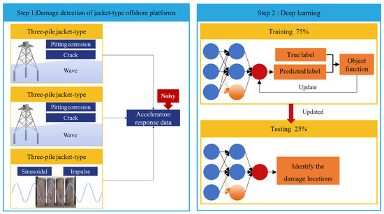
Figure 1.
The framework of proposed damage identification.
2.1. Construction of MSCNN
As shown in Figure 2, the MSCNN is designed to extract features from time series data using convolutional kernels of different scales, enhancing the model’s ability to perceive multi-scale features. The model consists of three parallel 1D convolutional branches, each employing convolutional kernels of sizes 1, 2, and 4, respectively. These branches share the same stride (stride = 1) and padding strategy to ensure consistent output dimensions, facilitating feature fusion. Each branch includes three Conv1D layers, each followed by a LeakyReLU activation function (α = 0.01), MaxPooling (with kernel size equal to the corresponding convolutional kernel size), and a BatchNormalization layer to accelerate training and improve stability. The number of channels increases progressively from 32 in the first layer to 64 and then 128. Afterward, each branch output is flattened into a 1D vector using the Flatten() operation and then concatenated along the feature dimension using a concatenate layer, resulting in a unified high-dimensional feature representation tensor. This representation is further passed into a multi-head attention module with a class token, which introduces global dependencies to strengthen feature representations. Only the output corresponding to the class token is retained as a global semantic representation, which is then fed into a fully connected layer followed by a Softmax layer for multi-class classification. This architecture effectively combines local multi-scale feature extraction and global attention mechanisms, significantly improving the model’s capability in representing and discriminating complex time series data.
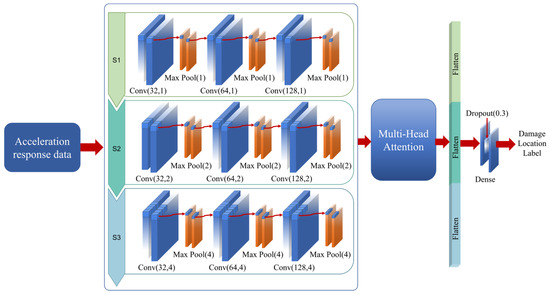
Figure 2.
The structure diagram of MSCNN-MHA.
To evaluate the model’s sensitivity to key hyperparameters, this study conducted comparative experiments on parameters such as convolution kernel size, dropout rate, and learning rate. First, in the multi-scale convolution module, kernel sizes of 1, 2, and 4 were used in combination. Compared with single-scale convolution, the multi-scale structure significantly enhanced the model’s feature extraction capability under complex vibration patterns. Second, for the dropout parameter, values of 0.1, 0.3, and 0.5 were tested. The results showed that a dropout rate of 0.3 effectively suppressed overfitting while maintaining a high model accuracy. Finally, for learning rate sensitivity testing, initial learning rates of 0.01, 0.001, and 0.0001 were examined. Experimental results indicated that the model was most stable when the learning rate was set to 0.0001, with a smoother decline in validation loss and higher accuracy. Therefore, this study ultimately adopted the combination of convolution kernel sizes of 1, 2, and 4, a dropout rate of 0.3, and an initial learning rate of 0.0001 as the optimal hyperparameter configuration.
In MSCNN, a simplified example of the convolution operation is illustrated in Figure 3. The convolution kernel starts from the top-left corner of the input data and slides across the data according to the specified stride. At each sliding window position, every element of the kernel (i, j, k) performs an element-wise multiplication with the corresponding input region (a, b, c), and the results are summed to produce a feature response value (ai + bj + ck). The kernel continues sliding, producing successive outputs such as (bi + cj + dk) and (ci + dj + ek).
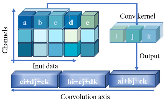
Figure 3.
Example of convolutional operations.
2.2. Construction of MHA
To enhance the model’s ability to understand overall data patterns, this study introduces a multi-head attention mechanism module incorporating a class token. The goal is to embed a global representation on top of the original multi-scale features, enabling better capture of the comprehensive characteristics of time-series data. Compared with the standard MSCNN, the deep learning model enhanced with multi-head attention demonstrates improved sensitivity and discriminative power in identifying complex damage features.
At the beginning of the module, a new vector is initialized for each input sample, serving as the class token. This token has the same dimensionality as the input feature channels and is defined as a trainable parameter. The class token is then duplicated according to the batch size so that each sample receives its own independent token. Subsequently, the class token is concatenated with the multi-scale features extracted by the convolutional neural network. The resulting sequence, organized per sample, consists of one class token followed by multiple feature vectors. This concatenated sequence is then fed into a multi-head attention mechanism. In this study, the attention mechanism uses four heads, with each head having a key dimension of 64, and a dropout rate of 0.1 is applied to mitigate overfitting. This configuration sets the total attention dimension to 256, ensuring structural consistency with the convolutional features from the preceding layer while balancing modeling capacity and computational efficiency. Compared to a single-head attention module, the multi-head mechanism enables the model to capture potential relationships within sequences and among measurement points from multiple perspectives, thereby enhancing the expressiveness of feature representations.
The attention output is added to the original sequence through a residual connection, followed by a layer normalization operation to stabilize the training process and enhance the representational capacity of the network. After normalization, the features are further passed through a feedforward sub-network consisting of two fully connected layers. The first dense layer outputs a 256-dimensional vector with a ReLU activation function, followed by a dropout layer with a rate of 0.3 to improve generalization. The second dense layer then projects the feature vector back to its original dimensionality. This output is again added to the previous residual path and undergoes another layer normalization. Finally, the class token representation vector produced by the multi-head attention module is passed through a fully connected layer with 256 units, followed by a dropout layer and a LeakyReLU activation function (α = 0.01), before being fed into the final Softmax layer for multi-class classification.
Through this mechanism, the model not only retains local convolutional features but also learns global distribution characteristics of the samples, thereby improving classification performance. In summary, the introduction of a multi-head self-attention module before the fully connected layers of the multi-scale convolutional neural network enables the model to effectively integrate local feature extraction with global relationship modeling, thereby improving the accuracy of crack and pitting corrosion damage identification in jacket-type offshore platforms.
Compared with traditional structural health monitoring methods (e.g., modal parameter variation analysis, wavelet analysis), the proposed approach offers significant advantages in feature extraction and adaptability. Traditional methods rely on predefined feature extraction procedures, are more susceptible to noise, and face certain limitations when dealing with complex conditions such as multiple damages, multiple measurement points, and nonlinear responses. In contrast, the MSCNN-MHA model developed in this study, based on deep learning, enables automatic feature extraction and modeling, effectively processes multi-source complex data, and demonstrates superior performance in both identification accuracy and scalability.
3. Numerical Simulation
3.1. Description of the Jacket-Type Offshore Platform
In this study, finite element models were developed for both three-pile and four-pile jacket-type offshore platforms, as illustrated in Figure 4A and Figure 4B, respectively. To accurately reflect the structural characteristics of offshore platforms, the model incorporates essential material parameters such as mass density, Poisson’s ratio, and Young’s modulus. Specifically, the mass density was set to 7850 kg/m3, the Poisson’s ratio was assigned a value of 0.3, and the Young’s modulus was set at 210 GPa. In simulating the effects of pile–soil interaction, due to the lack of detailed sediment layer data, this study adopts an equivalent pile–soil fixation approach. Specifically, a fixed boundary is set at a depth six times the pile leg diameter below the mudline to simulate the interaction between the pile and the soil. This approach effectively characterizes the axial stiffness properties of the piles while simplifying the analytical process and enhancing the model’s applicability in the absence of comprehensive sediment data. To simulate the stochastic wave loads in the marine environment, the JONSWAP spectrum was adopted, providing an accurate representation of wave generation, propagation, and dissipation. In the numerical analysis, incident wave directions were set along the orthogonal X and Z axes. For the X direction, the random wave height was set to 8 m, with a characteristic period of 7.4 s. For the Z direction, the wave height was set to 12.8 m, with a characteristic period of 13 s. To enhance the nonlinearity of the waveforms, a peak enhancement factor of 3.3 was used.
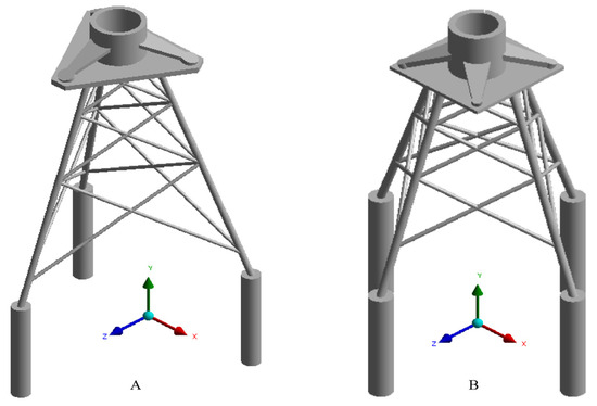
Figure 4.
Finite element model of three-pile jacket-type offshore platform (A) and four-pile jacket-type offshore platform (B).
The dynamic analysis method based on acceleration response signals offers significant advantages, as it can effectively reflect the dynamic characteristics of the platform and serve as a critical feature for damage identification. Therefore, in the model analysis process, this study collects Y-axis acceleration response signals from fixed points of three-pile and four-pile jacket-type offshore platforms. By systematically collecting acceleration response signals under various damage cases, the MSCNN-MHA algorithm model is applied for classification, thereby validating the scientific reliability and effectiveness of this algorithm in the structural health monitoring of jacket-type offshore platforms.
3.2. Setup of Crack Damage Cases
Offshore platforms are subjected to complex environmental loads such as waves, wind, and currents over long periods, making their structures prone to stress concentration under cyclic fatigue loading, which significantly reduces material fatigue life. The regions with maximum stress are susceptible to crack initiation and corrosion damage due to continuous tensile and compressive cycles, with such damage progressively propagating under accumulated cyclic loads, potentially leading to structural failure of jacket-type offshore platforms. Therefore, this study, based on numerical simulation analysis, identifies significant differences in stress distribution between three-pile and four-pile jacket-type offshore platforms, with their maximum stress regions located in different structural areas. Consequently, cracks were inserted into the respective maximum stress regions to more accurately assess the damage cases of different platform structures under complex loading scenarios.
Specifically, in the three-pile jacket-type offshore platform, the maximum stress is located in the C6 region, as shown in Figure 5. The three-pile jacket-type offshore platform designed in this study has a three-layer structure, resulting in a total of six critical regions (C1, C2, C3, C4, C5, and C6) that are prone to damage. The crack damage settings in this study are located within these critical regions. Each region contains only one crack, positioned at the point of maximum stress concentration within the respective area. Studies have shown that semi-elliptical cracks are likely to form on the surfaces of marine structures in real engineering environments [26]. Therefore, in this study, semi-elliptical cracks with a major axis radius of 0.005 m and a minor axis radius of 0.005 m are introduced to simulate small-scale damage. As shown in Figure 6, a schematic diagram of the crack enlarged 200 times is presented.
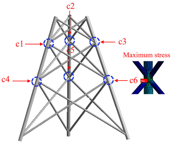
Figure 5.
The region of maximum stress in the three-pile jacket-type offshore platform.
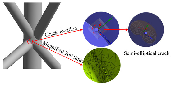
Figure 6.
Schematic diagram of the crack magnified 200 times.
As shown in Table 1, the single-damage cases of the three-pile jacket-type offshore platform are defined as c1 to c6, corresponding to labels 1, 2, 3, 4, 5, and 6, respectively. To further simulate potential damage scenarios, this study also introduces multi-damage cases, including double-damage and triple-damage cases. These multi-damage cases are formed by combining different single-damage cases, with the specific combinations shown in Table 2. This condition design is intended to simulate structural responses under complex damage scenarios and provides a reliable basis for subsequent damage identification and assessment.

Table 1.
Label for single-damage situation in a three-pile jacket offshore platform.
Table 2.
Label for multi-damage situation in a three-pile jacket offshore platform.
For the four-pile jacket-type offshore platform, this study establishes four single-damage cases, as shown in the Figure 7. The crack insertion points are located at C1, C2, C3, and C4 (with one crack inserted in each region), and each crack is positioned at the point of maximum stress within each region. The shape of the inserted cracks is identical to those used for the three-pile jacket-type offshore platform.
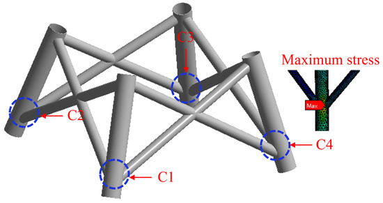
Figure 7.
The region of maximum stress in the four-pile jacket-type offshore platform.
As shown in Table 3, the single-damage cases for the four-pile jacket-type platform are labeled 1 to 4, corresponding to C1 through C4, respectively. Additionally, multi-damage cases, including double-damage and triple-damage scenarios, are also established. In a similar manner, the multi-damage cases are formed by combining various single-damage cases, with the detailed combinations presented in Table 4. This damage case design allows for a more comprehensive simulation of damage scenarios for jacket-type offshore platforms in real engineering environments, providing essential references for damage detection and structural safety assessment.
Table 3.
Label for single-damage case in a four-pile jacket offshore platform.
Table 4.
Label for multi-damage case in a four-pile jacket offshore platform.
Results of the Damage Localization
During the numerical simulation process, transient analysis was used to collect the acceleration response signals of the model. The sampling duration was set to 4500 s, with a sampling period of 1 s, resulting in each acceleration sensor channel collecting data for 4500 points.
As shown in Figure 1, the collected acceleration response signals were input into the Step2 deep learning model, and the dataset was divided, with 75% of the data used for training and the remaining 25% for testing. Table 5 lists the detailed information of the MSCNN-MHA architecture applied in this study, including the learning rate, number of training epochs, optimizer, and loss function. The batch size during training was set to 16. Additionally, to prevent overfitting, we incorporated an early stopping strategy (patience = 100) and a learning rate decay mechanism, where the learning rate is progressively reduced by a factor of 0.5 when the validation loss shows no improvement.
Table 5.
Parameter settings.
In this study, the input data fed into the convolutional neural network is derived from the fused results of vibration signals collected under various working conditions and from multiple measurement points. In this study, to adapt to the MSCNN-MHA model architecture, the collected raw vibration data underwent normalization and dimensional transformation. First, the Min-Max normalization method was applied to scale all input features to the [0, 1] range, eliminating the influence of different units and improving model convergence efficiency. As illustrated in Figure 8, a total of 18 measurement points were deployed on a three-pile jacket-type offshore platform structure to capture acceleration response signals in the axial direction (Y-axis of the global coordinate system). The data length collected at each measurement point is 4500. Therefore, the data dimension corresponding to each working condition is 18 × 4500. To provide a more intuitive illustration of the signal characteristics, Figure 9 presents the waveforms of 1000 acceleration response values extracted from each of four selected measurement points under the first single-damage condition. For the six single-damage conditions and one undamaged condition, the overall dataset has a dimension of 7 × 18 × 4500. To adapt the data to the algorithm model, the raw data is standardized, resulting in 1260 datasets, each with a dimension of (18, 25). During the model training phase, the datasets are randomly divided into a training set and a testing set, with the training set accounting for 75% (945 datasets) and the testing set 25% (315 datasets).
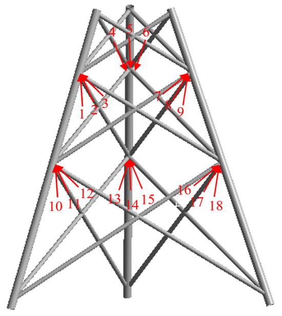
Figure 8.
The 18 locations of axial acceleration response data acquisition.
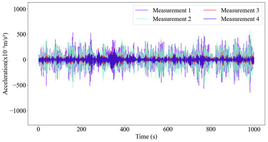
Figure 9.
Acceleration response waveforms of four points (1000-sample excerpt) under the first single-damage condition.
As shown in Table 6, the experimental results indicate that after 500 iterations, the MSCNN-MHA model achieves an identification accuracy of 92.4% for single-damage conditions of the three-pile jacket offshore platform. The corresponding confusion matrix is shown in Figure 10A. As also presented in Table 7, for the four multi-damage conditions, the MSCNN-MHA model achieves an identification accuracy of 96.1%, with the confusion matrix illustrated in Figure 10B.
Table 6.
Prediction of single-damage locations in the three-pile jacket-type offshore platform.
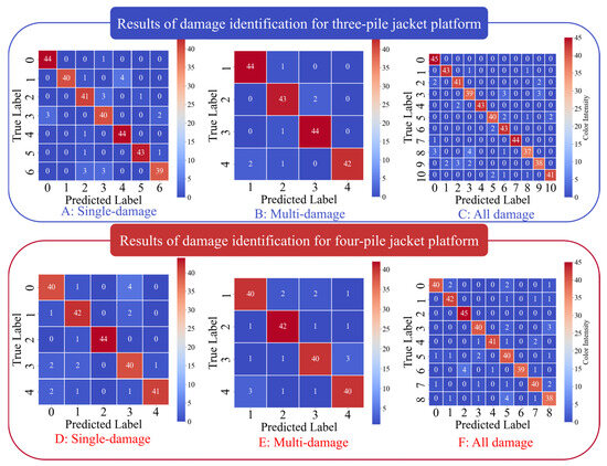
Figure 10.
Confusion matrix diagram obtained from the working conditions of three-pile and four-pile jacket offshore platforms.
Table 7.
Prediction of multi-damage locations in the three-pile jacket-type offshore platform.
To better simulate real-world damage cases, this study further combines single-damage and multi-damage cases, assigning the labels 7, 8, 9, and 10 to the multi-damage scenarios. After training the deep learning model, the overall recognition accuracy for these combined cases reached 91.7%, with a 100% recognition rate for the component corresponding to label 0. The confusion matrix is shown in Figure 10C. The research results validate the effectiveness of the model in complex damage identification cases.
For the four-pile jacket-type offshore platform, a total of 12 measurement points were arranged to collect axial acceleration response signals, as shown in Figure 11. Therefore, for each damage condition, the dataset input into the MSCNN-MHA model has a dimension of 12 × 4500. Although a total of 4500 acceleration response data points were collected for each measurement point in this experiment, only 1000 data points from each of four measurement points are shown in Figure 12 to improve readability. The complete dataset, which includes four single-damage conditions and one undamaged condition, initially has a dimension of 5 × 12 × 4500. After standardization to match the input format of the algorithm model, it is transformed into 900 samples, each with a dimension of (12, 25). In the model training process, the data are randomly partitioned into training and testing subsets, with 75% allocated for training and the remaining 25% reserved for testing. According to the experimental results presented in Table 8 and Table 9, the MSCNN-MHA model achieves identification accuracies of 92% for single-damage conditions and 90% for multi-damage conditions of the four-jacket offshore platform after 500 iterations. The corresponding confusion matrices are displayed in Figure 10D,E.
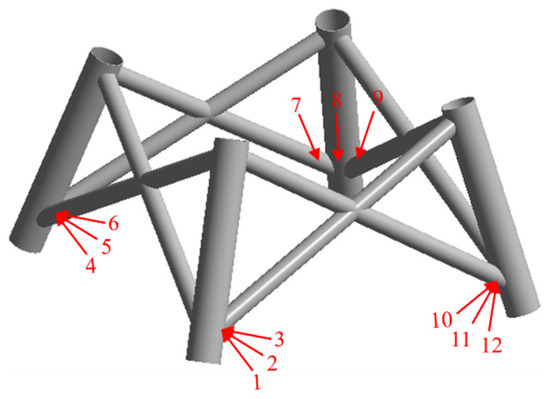
Figure 11.
The 12 locations of axial acceleration response data acquisition.
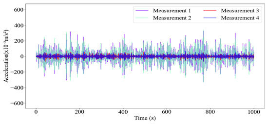
Figure 12.
Acceleration response waveforms of four points under the first single-damage condition (1000 of 4500 samples shown).
Table 8.
Prediction of single-damage locations in the four-pile jacket-type offshore platform.
Table 9.
Prediction of multi-damage locations in the four-pile jacket-type offshore platform.
To better reflect real-world engineering conditions, single-damage and multi-damage cases were combined, and the labels for multi-damage cases were sequentially adjusted to 5, 6, 7, and 8 in the table. After training the deep learning model, the accuracy reached 90.1%, with recognition rates of 100% for cases labeled 2. The confusion matrix is shown in Figure 10F. Therefore, the MSCNN-MHA model proposed in this study is also effective in identifying damage locations for the four-pile jacket-type offshore platform.
3.3. Pitting Corrosion Damage Cases
Jacket-type offshore platforms are primarily constructed from large steel pipes welded together, with the welded intersections referred to as nodes. These nodes typically bear the greatest stress and are challenging to protect, making them prone to damage such as corrosion and cracks. Pitting corrosion is a common type of localized damage in these platforms, often caused by seawater corrosion, temperature fluctuations, and other environmental factors. This damage can gradually accumulate and intensify over time. Both pitting and crack damage not only shorten the service life of offshore platforms but also compromise structural integrity, potentially leading to severe safety incidents. Therefore, accurately identifying and assessing pitting and crack damage is of great importance in practical engineering applications.
Pitting corrosion is a localized form of corrosion. Based on the statistical analysis of pitting corrosion data from actual marine structures, it has been found that the maximum diameter of pits is typically less than 0.08 m. Research indicates that when the shape of the pit is hemispherical, the diameter-to-depth ratio ranges between 6:1 and 4:1 [27,28]. The formula for calculating the diameter-to-depth ratio is as follows:
where λ represents the diameter-to-depth ratio, d is the diameter of the pitting pit, and h is its depth. In this study, small-scale pitting corrosion that does not fully penetrate the jacket structure is simulated by introducing hemispherical pits with a diameter of 0.065 m and a depth of 0.015 m.
λ = d/h
As illustrated in Figure 13, to simplify the experiment, this study simulates pitting and crack damage at the locations of maximum stress in a three-pile jacket-type offshore platform. A total of six damage cases (P1, P2, P3, P4, P5, and P6) and one intact case (denoted as P0) were established, as summarized in Table 10. The intact case is labeled as 0, while pitting damage cases are assigned labels 1, 2, and 3. To better reflect real-world engineering conditions, additional damage scenarios involving both pitting and cracks were introduced, corresponding to labels 4, 5, and 6. At the points of maximum stress on the offshore platform, the locations indicated by arrows 1, 2, 3, and 4 in the P1 case of Figure 13 were selected as measurement points for collecting acceleration response signals. Therefore, for each damage condition, the dataset input into the MSCNN-MHA model has a dimension of 4 × 4500. As shown in Table 10, there are a total of seven conditions, including both undamaged and damaged scenarios, resulting in an overall data dimension of 7 × 4 × 4500. A total of 1260 datasets are generated, each with a dimension of 4 × 25. From the overall dataset, 75% (945 datasets) are randomly selected for training, while the remaining 25% (315 datasets) are used as the testing set. As shown in Table 11 and Figure 14, the overall recognition accuracy reached 92.1%. Therefore, the proposed MSCNN-MHA algorithm model is also effective in identifying the locations of pitting and crack damage in jacket-type offshore platforms.
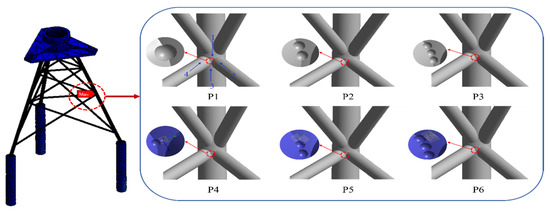
Figure 13.
Simulation of pitting and crack damage at the maximum stress location.
Table 10.
Pitting and crack damage cases.
Table 11.
Prediction of all damage locations under pitting corrosion damage cases.
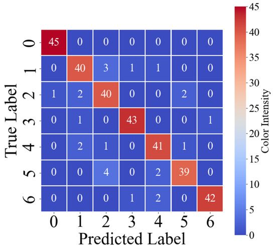
Figure 14.
Confusion matrix obtained from pitting damage cases.
3.4. Comparison of CNN, MSCNN, and MSCNN-MHA for Damage Localization
To verify the effectiveness of the MSCNN-MHA model in identifying complex damage cases, this study compares it with the CNN and MSCNN models. The parameter settings for the CNN and MSCNN models are shown in Table 5. The Adam optimizer and cross-entropy loss function are also used during the training process. The CNN model adopts a three-layer one-dimensional convolutional architecture for feature extraction, using 32, 64, and 128 convolutional filters, respectively. The Leaky ReLU activation function is applied for nonlinear transformation. After feature extraction, the output is flattened and passed through a fully connected layer with 128 nodes, followed by a Softmax layer for classification. For the MSCNN model, all parameter settings are kept consistent with the MSCNN component in the MSCNN-MHA model, except that the MHA module is removed.
The damage localization results for all crack and pitting damage cases in both three-pile and four-pile jacket-type offshore platforms are presented in Table 12. Among the three algorithm models, the MSCNN-MHA model achieves the highest prediction accuracy across various damage scenarios, all exceeding 90%. However, its computation time is higher compared to the other two models. The table also shows that the MSCNN model outperforms the CNN model in terms of recognition accuracy. This strongly validates the effectiveness of incorporating the MHA module into the MSCNN model. The training in this study was conducted on a computer equipped with an Intel(R) Core(TM) i7-14700HX 2.10 GHz processor, 16 GB of RAM, running Windows 11, using Python 3.8 and TensorFlow 2.6.0.
Table 12.
Comparison of accuracy and computation time of the three methods under all damage cases.
3.5. Damage Localization Under Noise Condition
Studies have indicated that the environmental noise affecting offshore structures can often be reasonably modeled as Gaussian white noise excitation [29,30]. In order to more faithfully replicate the actual acquisition conditions of acceleration response signals, Gaussian white noise with intensities of 10%, 20%, and 30% was superimposed onto the collected signals [3]. This noise was independently applied to each sensor channel to realistically represent the localized disturbances commonly present in multi-source data acquisition systems. The noisy signal is modeled as follows:
where the Noisy signal represents the output after adding noise, the Raw signal is the original acceleration response signal, ε denotes the noise intensity, and R is Gaussian white noise with a mean of 0 and a variance of 1. As shown in Figure 15, it represents the original signal collected from the first measurement point of the first crack damage case of the three-pile jacket-type offshore platform, with 10% Gaussian white noise added to the signal. Figure 16 shows the acceleration response signal collected from the first measurement point under the first pitting damage case, after adding 20% Gaussian white noise.
Noisy signal = Raw signal × (1 + εR)
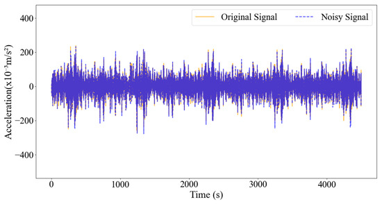
Figure 15.
Add 10% Gaussian white noise to the first measuring point of the first crack damage case.
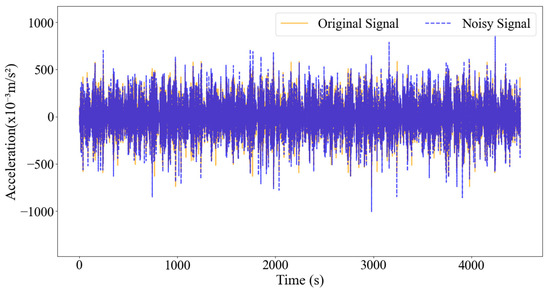
Figure 16.
Add 20% Gaussian white noise to the first measuring point of the first pitting damage case.
For crack damage scenarios (including single-damage and multi-damage cases, as well as intact conditions for comparison), the average recognition accuracy for damage identification was 90.7% and 89.6% for three-pile and four-pile jacket platforms, respectively, under a low noise level of 10%. At a moderate noise level of 20%, the damage identification accuracy was 88.9% and 88.4% for the three-pile and four-pile platforms, respectively. Even at a high noise level of 30%, the damage identification accuracy remained relatively stable at 85.9% and 87.7% for the three-pile and four-pile jacket platforms, respectively.
Under the overall working condition of pitting damage, the damage identification accuracy reaches 90.5% at a low noise level of 10%, 88.6% at a moderate noise level of 20%, and remains as high as 87.3% at a high noise level of 30%. The results demonstrate that the identification accuracy consistently exceeds 85.9% regardless of the noise level. The experimental results clearly demonstrate that the MSCNN-MHA algorithm exhibits excellent noise resistance, maintaining reliable damage identification performance even in the presence of complex noise interference.
4. Experimental Study
To verify the effectiveness of the MSCNN-MHA algorithm model in practical engineering applications, this paper conducts an experimental study on the fundamental structural steel pipes of the jacket-type offshore platform. A total of four steel tubes were custom-fabricated for this study, each with a length of 0.3 m, an outer diameter of 0.102 m, and a wall thickness of 0.005 m. During the experiment, the bottom end of each steel tube was securely fixed to the test platform. Four acceleration sensors were installed at 0.06 m intervals along the tube to monitor its dynamic response, as illustrated in Figure 17.
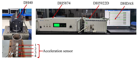
Figure 17.
Experimental setup for steel pipe testing.
In this study, as illustrated in Figure 18, four cases were established, including one intact case (E0) and three damaged cases (E1, E2, and E3). All pitting and crack damage features were set to the same size. The first damage case involves designing a hemispherical pit with a diameter of 0.005 m and a depth of 0.003 m at a position 0.15 m from the bottom end of the circular tube to simulate pitting corrosion. Additionally, a crack with a length of 0.01 m and a depth of 0.003 m is placed 0.01 m to the right of the pit. The second damage case builds upon the first steel tube by adding another pitting corrosion pit and crack at a position 0.014 m below the first pit. The third damage case adds a group of pitting corrosion and cracks of the same size on the basis of the second damage case. The spacing between the damages corresponds to regions with significant stress gradient variations, thereby effectively covering damage scenarios under different stress levels and facilitating the evaluation of the model’s identification performance. The configuration of these cases is summarized in Table 13, where E1, E2, and E3 represent the three damaged cases with corresponding labels of 1, 2, and 3, respectively, while E0 denotes the intact cylindrical tube with a label of 0.
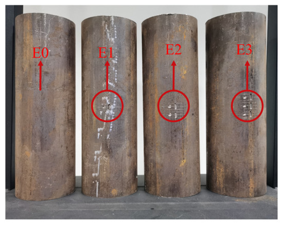
Figure 18.
Four distinct damage scenarios.
Table 13.
All damage cases in the experiment.
The DH5922D dynamic signal testing and analysis system was employed to monitor the structural vibration signals in real time. Additionally, the DH5874 power amplifier was used to ensure the stability and repeatability of the experimental signals. To simulate various working conditions, a DH40 series exciter was utilized to adjust the vibration amplitude and frequency, primarily generating sinusoidal and impulse excitation signals. All excitation points were positioned 0.23 m from the bottom of the cylindrical tube. The experimental setup is shown in Figure 17. The experimental part of this study selected sinusoidal and impulse excitations as input excitations [3], aiming to validate the model’s performance under typical frequency-domain and transient loading in a controlled environment.
4.1. All Damage Cases Under a Sinusoidal Excitation
Under sinusoidal excitation, four damage cases were simulated: (1) one pitting and one crack, (2) two pitting and two cracks, (3) three pitting and three cracks, and (4) an intact case. The steel tube was excited using a vibration exciter, with excitation parameters configured in the DHDAS (6.22) software. The excitation type was set to fixed-frequency sinusoidal, with an amplitude of 1000 mV and a frequency of 1 Hz. A four-channel acceleration sensor acquisition system was used to collect acceleration response signals, with a sampling frequency of 1000 Hz and a sampling duration of 30 s. Each damage case dataset has a dimension of 4 × 30 × 1000. As shown in Figure 19, the acceleration response signals collected from four measurement points under the first damage case are presented. Due to the large data length, only 1000 data points are displayed in the figure. For the three damage conditions and one undamaged condition, the dataset has a dimension of 4 × 4 × 30 × 1000. A total of 800 datasets are generated, each with a dimension of 4 × 150. In the MSCNN-MHA model, 80% of the total dataset is used as the training set, while the remaining 20% is used as the testing set. After training and testing with the MSCNN-MHA model, the classification accuracy reached 93.1%. Table 14 presents a comparison between the actual and predicted labels for each damage case.
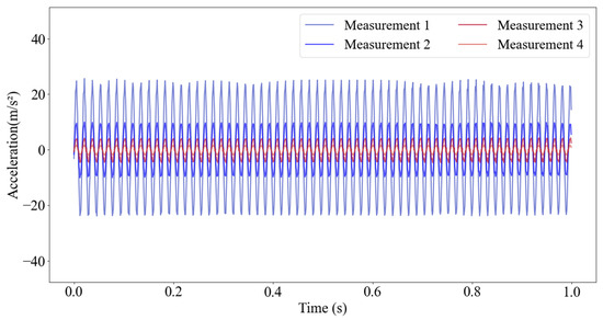
Figure 19.
Acceleration signals at four points were collected under sinusoidal excitation in the first damage case.
Table 14.
Prediction results of all damage cases under sinusoidal excitation.
4.2. All Damage Cases Under an Impulse Excitation
Under impulse excitation, the same four damage cases were simulated. The exciter was used to vibrate the steel tube, and the DHDAS software was configured with impulse-type excitation, an amplitude of 1000 mV, and a period of 1 s. A 4-channel acceleration sensor system was used to collect acceleration response signals, operating at a sampling frequency of 1000 Hz over a 30 s duration. As shown in Figure 20, a partial view of the first damage case is presented, where 1000 acceleration response signals are collected from four measurement points under impulse excitation. Before inputting the data into the algorithm model, the dataset is constructed in the same way as for the sinusoidal excitation condition. The experimental results show that the model achieved a damage case recognition accuracy of 93.8%. The comparison of the true and predicted labels for each case is provided in Table 15.
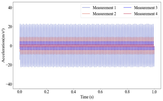
Figure 20.
Acceleration signals at four points were collected under impulse excitation in the first damage condition.
Table 15.
Prediction results of all damage cases under impulse excitation.
The experimental results indicate that the damage identification accuracy exceeds 93.1% under both sinusoidal and impulse excitations. Since environmental noise was inherently present during the experiments, no additional noise interference was introduced.
4.3. Comparison of CNN, MSCNN, and MSCNN-MHA for Damage Localization
To verify the effectiveness of the MSCNN-MHA model under actual experimental conditions, it is also compared with the CNN and MSCNN models. As shown in Table 16, the MSCNN-MHA model achieves the highest accuracy in identifying damage cases under both sinusoidal and impulse excitations, although its computation time is higher than that of CNN and MSCNN. The study found that, under both sinusoidal and pulse excitations, MSCNN achieved higher identification accuracy for damage conditions than CNN, although its computation time was longer than that of CNN. These experimental results confirm the effectiveness of the MSCNN-MHA model in damage identification, demonstrating that it can accurately locate damage even under small-scale damage cases.
Table 16.
Comparison of accuracy and computation time of the three methods under all damage cases.
5. Conclusions
This paper proposes a structural health monitoring method based on the MSCNN-MHA algorithm model, which enhances the accuracy of detecting small-scale damage in jacket-type offshore platforms. Through numerical simulation analysis of the jacket platform and experimental verification of its basic structure, the effectiveness and applicability of this method in structural damage detection are demonstrated. The main conclusions of this paper are as follows.
- Under stochastic wave force excitation with varying wave directions and heights, the MSCNN-MHA model demonstrates high accuracy in identifying both small-scale crack and pitting damage in jacket-type offshore platforms. Experimental results indicate that the recognition accuracy of the proposed method exceeds 90% across different damage cases, confirming its effectiveness and reliability in the structural health monitoring of offshore platforms.
- To simulate the complexities of real-world data acquisition, this study introduces Gaussian white noise interference under crack and pitting damage cases and evaluates the model’s robustness against noise. By adding Gaussian white noise at levels of 10%, 20%, and 30% to the original signals, the experimental results reveal that the MSCNN-MHA model maintains a damage recognition accuracy of over 85.9%. This finding verifies the noise resistance and stability of the proposed MSCNN-MHA algorithm in complex environments.
- To ensure the engineering applicability of the experimental results, this study employs fundamental structural steel tubes of jacket-type offshore platforms for testing. Acceleration response signals are collected under both sinusoidal and impulse excitation conditions, and the data is used to train and test the model. The experimental results show that the MSCNN-MHA model achieves classification accuracies of 93.1% and 93.8% under sinusoidal and impulse excitation, respectively.
The MSCNN-MHA algorithm proposed in this study can effectively identify small-scale cracks and pitting corrosion damage on jacket-type offshore platforms, with its performance validated through experiments. In real offshore environments, deploying the model requires careful consideration of sensor reliability, the feasibility of long-term monitoring, and limitations in data transmission bandwidth. Furthermore, variations in sensor placement and time resolution during data collection may affect model performance; this study applies data normalization and conducts multiple experiments to verify the model’s robustness against minor variations in data acquisition. Given the limited number of steel pipes used in the current experiments, future work will include (1) constructing an experimental platform based on real sea-state loading to better simulate structural responses; (2) incorporating specimens with different topologies and material parameters to assess model transferability; and (3) collecting field-measured data to verify engineering applicability. Additionally, the experimental scale will be expanded to cover more damage types and severity levels, improving the model’s robustness and accuracy under complex conditions. Although differences in structural form, dynamic characteristics, and environmental loading patterns among offshore structures may affect direct transferability, the proposed method is theoretically generalizable. Before applying it to other structures, adaptation and retraining tailored to their specific characteristics are necessary to ensure identification accuracy and reliability.
Author Contributions
Conceptualization, S.F. and L.S.; methodology, S.F. and Z.Y.; software, J.Z.; validation, Y.S.C., T.S. and S.W.; formal analysis, S.F. and J.Z.; resources, L.S.; data curation, T.S. and S.W.; writing—original draft preparation, S.F.; writing—review and editing, Z.Y. and Y.S.C.; funding acquisition, L.S. All authors have read and agreed to the published version of the manuscript.
Funding
This research was funded by Shandong Province Youth Entrepreneurship Technology Support Program for Higher Education Institutions, grant number No. 2022KJ211.
Data Availability Statement
The data presented in this study are available on request from the corresponding author.
Conflicts of Interest
Author Shoujun Wang was employed by the company CIMC Offshore Engineering Institute Co., Ltd. The remaining authors declare that the research was conducted in the absence of any commercial or financial relationships that could be construed as a potential conflict of interest.
References
- Yan, M.; Peng, Q.; Yin, Q. Study on stress corrosion crack of austenitic stainless steel in simulated ocean environment. Procedia Eng. 2012, 27, 1538–1543. [Google Scholar] [CrossRef]
- Yin, Z.; Li, Z.; Longchi, Z.; Wang, Y.; Huang, X. A Frequency-dependent High-cycle Fatigue Damage Model and Its Application in Crack Nucleation of Marine Riser from Corrosion Pits. Fatigue Fract. Eng. Mater. Struct. 2023, 46, 1488–1499. [Google Scholar] [CrossRef]
- Bao, X.; Fan, T.; Shi, C.; Yang, G. One-Dimensional Convolutional Neural Network for Damage Detection of Jacket-Type Offshore Platforms. Ocean Eng. 2021, 219, 108293. [Google Scholar] [CrossRef]
- Leng, J.; Incecik, A.; Wang, M.; Feng, S.; Li, Y.; Yang, C.; Li, Z. Damage Detection of Offshore Jacket Structures Using Structural Vibration Measurements: Application of a New Hybrid Machine Learning Method. Ocean Eng. 2023, 288, 116078. [Google Scholar] [CrossRef]
- Blachowski, B.; An, Y.; Spencer, B.F.; Ou, J. Axial Strain Accelerations Approach for Damage Localization in Statically Determinate Truss Structures. Comput. Aided Civ. Infrastruct. Eng. 2017, 32, 304–318. [Google Scholar] [CrossRef]
- Kouchaki, M.; Salkhordeh, M.; Mashayekhi, M.; Mirtaheri, M.; Amanollah, H. Damage Detection in Power Transmission Towers Using Machine Learning Algorithms. Structures 2023, 56, 104980. [Google Scholar] [CrossRef]
- Aghaeidoost, V.; Afshar, S.; Ziaie Tajaddod, N.; Asgarian, B.; Rahman Shokrgozar, H. Damage Detection in Jacket-Type Offshore Platforms via Generalized Flexibility Matrix and Optimal Genetic Algorithm (GFM-OGA). Ocean Eng. 2023, 281, 114841. [Google Scholar] [CrossRef]
- Leng, J.; Ma, J.; Fan, Z.; Qian, W.; Feng, H. Modal Parameter Identification Method of Jacket Platform Structure Based on AFDD and Optimized FBFFT. China Ocean Eng. 2023, 37, 393–407. [Google Scholar] [CrossRef]
- Mojtahedi, A.; Hokmabady, H.; Yaghubzadeh, A.; Mohammadyzadeh, S. An Improved Model Reduction-Modal Based Method for Model Updating and Health Monitoring of an Offshore Jacket-Type Platform. Ocean Eng. 2020, 209, 107495. [Google Scholar] [CrossRef]
- Mousavi, Z.; Varahram, S.; Mohammad Ettefagh, M.; Sadeghi, M.H. Dictionary Learning-Based Damage Detection under Varying Environmental Conditions Using Only Vibration Responses of Numerical Model and Real Intact State: Verification on an Experimental Offshore Jacket Model. Mech. Syst. Signal Process. 2023, 182, 109567. [Google Scholar] [CrossRef]
- Puruncajas, B.; Vidal, Y.; Tutivén, C. Vibration-Response-Only Structural Health Monitoring for Offshore Wind Turbine Jacket Foundations via Convolutional Neural Networks. Sensors 2020, 20, 3429. [Google Scholar] [CrossRef]
- Seventekidis, P.; Giagopoulos, D. A Combined Finite Element and Hierarchical Deep Learning Approach for Structural Health Monitoring: Test on a Pin-Joint Composite Truss Structure. Mech. Syst. Signal Process. 2021, 157, 107735. [Google Scholar] [CrossRef]
- Ghiasi, A.; Moghaddam, M.K.; Ng, C.-T.; Sheikh, A.H.; Shi, J.Q. Damage Classification of In-Service Steel Railway Bridges Using a Novel Vibration-Based Convolutional Neural Network. Eng. Struct. 2022, 264, 114474. [Google Scholar] [CrossRef]
- Wang, M.; Incecik, A.; Tian, Z.; Zhang, M.; Kujala, P.; Gupta, M.; Krolczyk, G.; Li, Z. Structural Health Monitoring on Offshore Jacket Platforms Using a Novel Ensemble Deep Learning Model. Ocean Eng. 2024, 301, 117510. [Google Scholar] [CrossRef]
- Ye, X.; Cao, Y.; Liu, A.; Wang, X.; Zhao, Y.; Hu, N. Parallel Convolutional Neural Network Toward High Efficiency and Robust Structural Damage Identification. Struct. Health Monit. 2023, 22, 3805–3826. [Google Scholar] [CrossRef]
- Jin, Y.; Qin, C.; Zhang, Z.; Tao, J.; Liu, C. A Multi-Scale Convolutional Neural Network for Bearing Compound Fault Diagnosis Under Various Noise Conditions. Sci. China Technol. Sci. 2022, 65, 2551–2563. [Google Scholar] [CrossRef]
- Zhang, W.; Li, J.; Huang, S.; Wu, Q.; Liu, S.; Li, B. Application of Multi-Scale Convolutional Neural Networks and Extreme Learning Machines in Mechanical Fault Diagnosis. Machines 2023, 11, 515. [Google Scholar] [CrossRef]
- Li, Y.; Du, X.; Wang, X.; Si, S. Industrial Gearbox Fault Diagnosis Based on Multi-Scale Convolutional Neural Networks and Thermal Imaging. ISA Trans. 2022, 129, 309–320. [Google Scholar] [CrossRef] [PubMed]
- Liang, H.; Cao, J.; Zhao, X. Multibranch and Multiscale Dynamic Convolutional Network for Small Sample Fault Diagnosis of Rotating Machinery. IEEE Sens. J. 2023, 23, 8973–8988. [Google Scholar] [CrossRef]
- Zhang, J.; Yu, D.; Li, G.; Dong, Z. Multi-Hazard Performance Assessment of Monopile Offshore Wind Turbine Considering Coupled Corrosion and Fatigue Damage. Ocean Eng. 2025, 316, 119985. [Google Scholar] [CrossRef]
- Wu, R.; Ren, Y.; Tan, M.; Nie, L. Fault Diagnosis of HVAC System with Imbalanced Data Using Multi-Scale Convolution Composite Neural Network. Build. Simul. 2024, 17, 371–386. [Google Scholar] [CrossRef]
- Shao, X.; Kim, C.-S. Adaptive Multi-Scale Attention Convolution Neural Network for Cross-Domain Fault Diagnosis. Expert Syst. Appl. 2024, 236, 121216. [Google Scholar] [CrossRef]
- Xu, Z.; Li, C.; Yang, Y. Fault Diagnosis of Rolling Bearings Using an Improved Multi-Scale Convolutional Neural Network with Feature Attention Mechanism. ISA Trans. 2021, 110, 379–393. [Google Scholar] [CrossRef]
- Wang, A.; Pei, Y.; Zhu, Y.; Qian, Z. Wind Turbine Fault Detection and Identification through Self-Attention-Based Mechanism Embedded with a Multivariable Query Pattern. Renew. Energy 2023, 211, 918–937. [Google Scholar] [CrossRef]
- Liu, Q.; Wang, J.; Dai, H.; Ning, L.; Nie, P. Bridge Structural Damage Identification Based on Parallel Multi-Head Self-Attention Mechanism and Bidirectional Long and Short-Term Memory Network. Arab. J. Sci. Eng. 2024, 50, 1803–1815. [Google Scholar] [CrossRef]
- Zou, X. Study on the Residual Strength of Jacket Platforms Under Crack Damage. Master’s Thesis, Jiangsu University of Science and Technology, Zhenjiang, China, 2014. [Google Scholar]
- Paik, J.K.; Thayamballi, A.K. Ultimate Strength of Ageing Ships. Proc. Inst. Mech. Eng. Part M J. Eng. Marit. Environ. 2002, 216, 57–77. [Google Scholar] [CrossRef]
- Paik, J.K.; Lee, J.M.; Ko, M.J. Ultimate Shear Strength of Plate Elements with Pit Corrosion Wastage. Thin-Walled Struct. 2004, 42, 1161–1176. [Google Scholar] [CrossRef]
- Tarpø, M.; Nabuco, B.; Georgakis, C.; Brincker, R. Expansion of Experimental Mode Shape from Operational Modal Analysis and Virtual Sensing for Fatigue Analysis Using the Modal Expansion Method. Int. J. Fatigue 2020, 130, 105280. [Google Scholar] [CrossRef]
- Brincker, R.; Ventura, C. Introduction to Operational Modal Analysis; John Wiley & Sons Inc.: Chichester, UK, 2015. [Google Scholar]


Disclaimer/Publisher’s Note: The statements, opinions and data contained in all publications are solely those of the individual author(s) and contributor(s) and not of MDPI and/or the editor(s). MDPI and/or the editor(s) disclaim responsibility for any injury to people or property resulting from any ideas, methods, instructions or products referred to in the content. |
© 2025 by the authors. Licensee MDPI, Basel, Switzerland. This article is an open access article distributed under the terms and conditions of the Creative Commons Attribution (CC BY) license (https://creativecommons.org/licenses/by/4.0/).