Article

HAUV-USV Collaborative Operation System for Hydrological Monitoring

1
MNR Key Laboratory for Geo-Environmental Monitoring of Great Bay Area, Shenzhen University, Shenzhen 518060, China
2
Shenzhen Institute for Advanced Study, University of Electronic Science and Technology of China, Shenzhen 518110, China
*
Author to whom correspondence should be addressed.
J. Mar. Sci. Eng. 2025, 13(8), 1540; https://doi.org/10.3390/jmse13081540
Submission received: 13 July 2025 / Revised: 4 August 2025 / Accepted: 8 August 2025 / Published: 11 August 2025
(This article belongs to the Section Ocean Engineering)

Abstract

Research in marine hydrographic environmental monitoring continues to deepen, necessitating a hardware platform capable of traversing air–water interfaces to collect vertical gradient parameters across oceanographic profiles. This paper proposes a deeply integrated heterogeneous monitoring platform for marine hydrological vertical profiling, addressing the functional limitations of conventional unmanned surface vehicles (USVs) and unmanned aerial vehicles (UAVs) in subsurface monitoring. By co-designing a hybrid aerial underwater vehicle (HAUV) with cross-domain capabilities and a USV, the system leverages USVs for long-endurance surface operations and HAUVs for high-speed vertical column monitoring. Key innovations include (1) a distributed collaborative architecture enabling “Air–Sea–Air” cyclic operations; (2) dynamic modeling of HAUV-USV interactions incorporating aerodynamic and hydrodynamic coupling; (3) an MPC-based collaborative tracking algorithm for real-time USV pursuit under marine disturbances; and (4) a vision-guided synchronous landing strategy achieving decimeter-level docking accuracy in bad conditions. Simulation experiments validate the system’s efficacy in trajectory tracking and precision landing. This work bridges the critical gap in marine vertical profile monitoring while demonstrating robust cross-domain coordination.

1. Introduction

Unmanned surface vehicles (USVs) and unmanned aerial vehicles (UAVs), using advantages such as intelligence, automation, and strong environmental adaptability, are widely utilized in the monitoring and development of the marine hydrological environment. Conventional USVs are capable of carrying out long-duration autonomous navigation missions. However, limitations in vessel speed hinder their ability to perform highly maneuverable fixed-point monitoring. Furthermore, USVs possess limited perception capabilities for dynamic marine environments and exhibit weaker obstacle avoidance and path-planning capabilities. These limitations pose navigational safety risks when USVs operate independently. UAVs, benefiting from high speed and excellent maneuverability, can rapidly conduct wide-area observations of the water surface, capturing high-definition images and video [1]. Although the autonomy and intelligence levels of UAVs continue to improve, their operational effectiveness in hydrological monitoring is significantly constrained by inherent limitations in endurance (flight time) and payload capacity [2]. Coupling these two heterogeneous systems: using the USV as a docking platform for the UAV and the UAV as an observation platform for the USV can effectively overcome the functional deficiencies of each individual system and significantly enhance overall functionality.
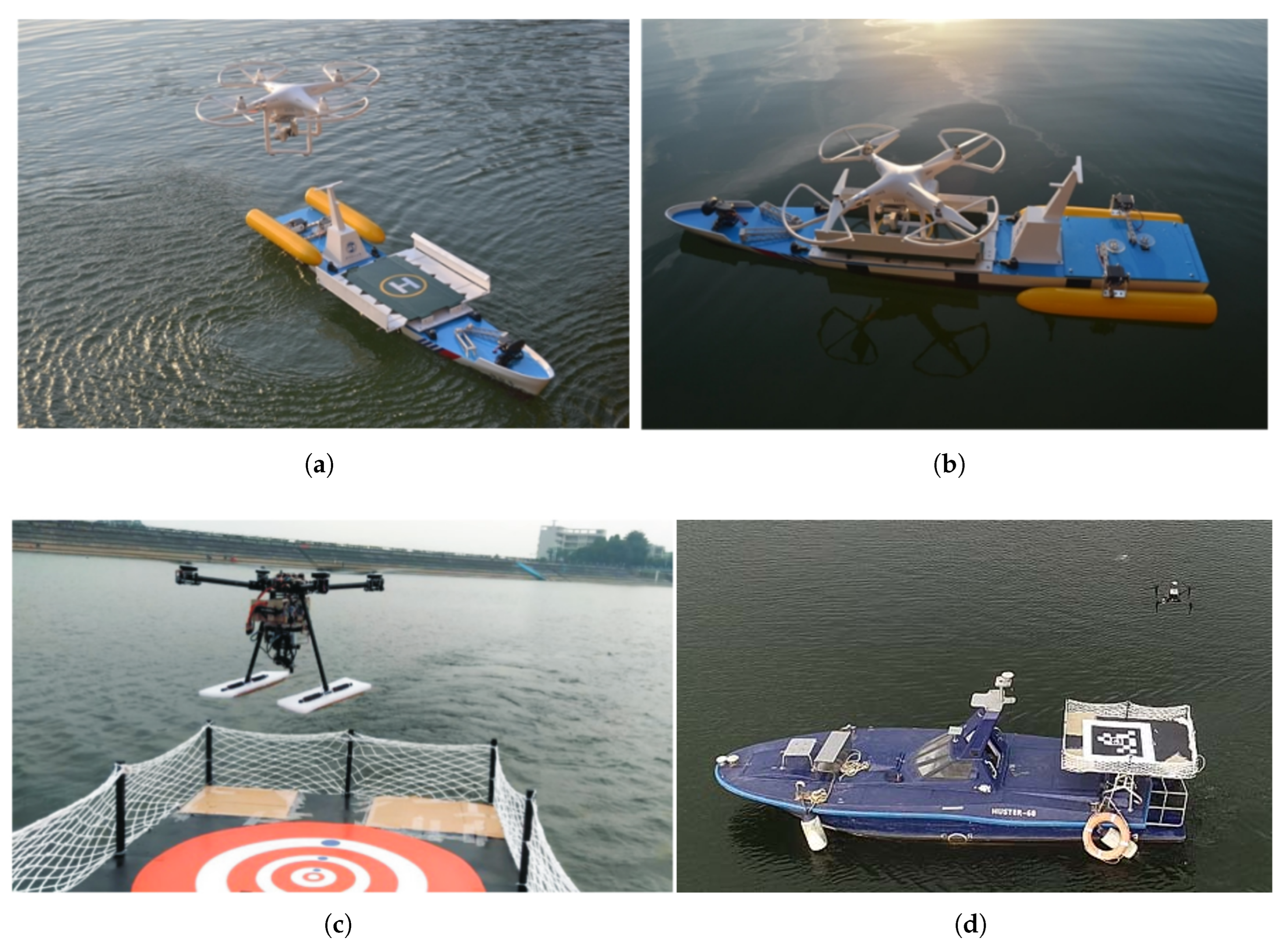
Research has been conducted on the collaboration between unmanned aerial vehicles (UAVs) and unmanned surface vehicles (USVs). Shao designed a novel collaborative platform for a UAV-USV coupled system [3]. This platform employs a multi-ultrasonic joint dynamic positioning algorithm to resolve localization challenges inherent in coupled unmanned reconnaissance systems. In addition, it uses a hierarchical waypoint-generation algorithm to achieve effective guidance for UAV landings on the USV (shown in Figure 1a,b). Young proposed a measurement method assisted by UAV-USV [4] (as shown in Figure 1c). This method integrates visual sensors mounted on the UAV to capture high-resolution images with sonar sensors deployed on the USV to acquire bathymetric readings, enabling effective UAV-USV coordination. Sanchez Lopez ensured robust UAV (as shown in Figure 1d) state estimation through a Kalman filter [5], thereby enabling vision-based autonomous landing. Xu developed a third-order visual detection method to estimate the relative pose between the UAV and the USV [6]. This estimation was subsequently used to control the UAV’s landing onto the USV, with the approach ultimately validated through lake-based experiments.
Current research on collaborative applications of UAV and USV remains primarily focused on surface and aerial observations. However, the complexity of the marine hydrological environment manifests not only at the surface but also significantly within the water column, which exhibits pronounced vertical gradients [7,8]. For instance, the vertical distribution structures of key oceanographic parameters—such as temperature, salinity, dissolved oxygen, and chlorophyll—are crucial for marine pollution monitoring, early warning systems, and climate change research. Consequently, existing UAV-USV collaborative paradigms exhibit a distinct functional gap concerning the monitoring of subsurface hydrological environments [9]. The emergence of hybrid aerial underwater vehicles (HAUVs), however, demonstrates their potential for enabling cross-domain monitoring capabilities.
A hybrid aerial underwater vehicle is an unmanned vehicle capable of operating both underwater and in the air. It possesses the ability to repeatedly cross the air–water interface using its own power and can perform aquatic and aerial tasks when equipped with appropriate sensors [10,11]. This vehicle combines the maneuverability typical of underwater robots with the high-speed advantage inherent in aerial vehicles. Multirotor amphibious UAVs achieve locomotion control through the operation of multiple rotors. They feature vertical take-off and landing as well as hovering capabilities, offering high flexibility and controllability. When optimized for oceanographic profile observation applications, they present an ideal platform for subsurface vertical column monitoring.
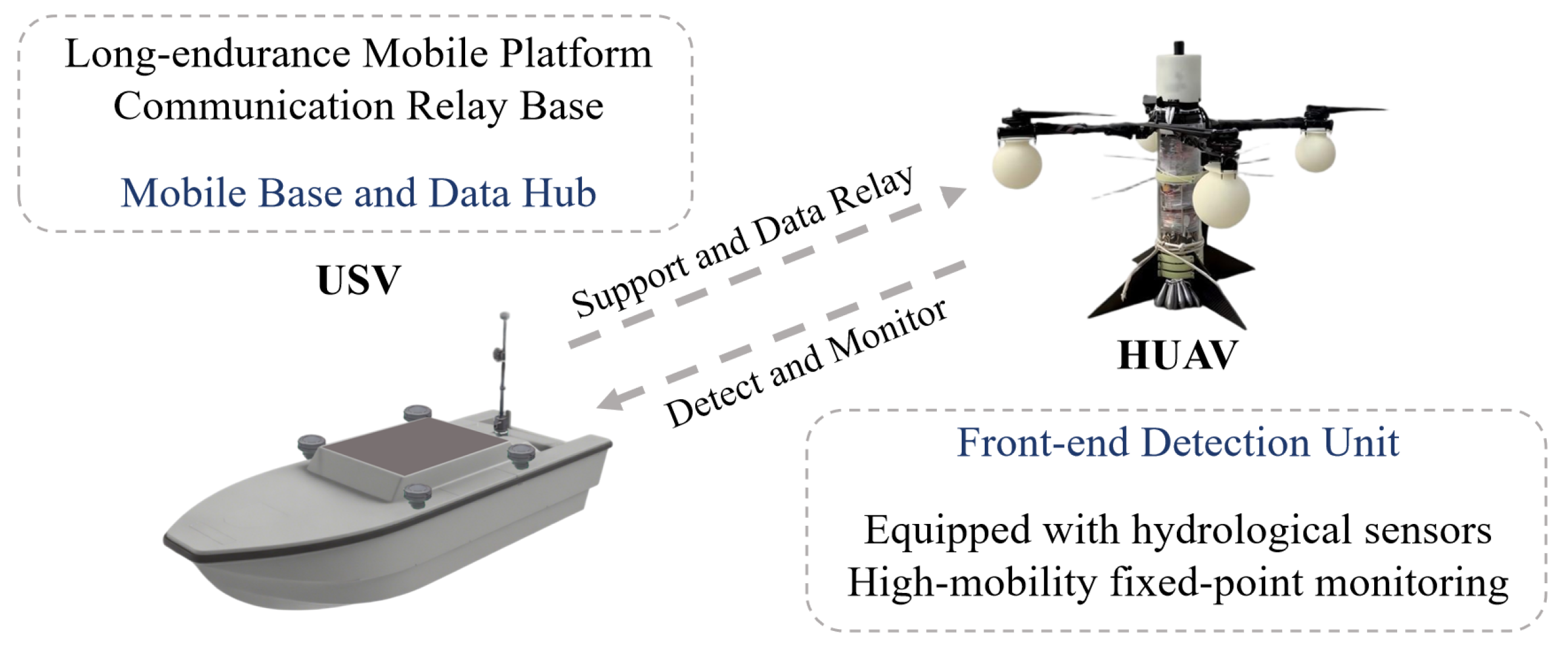
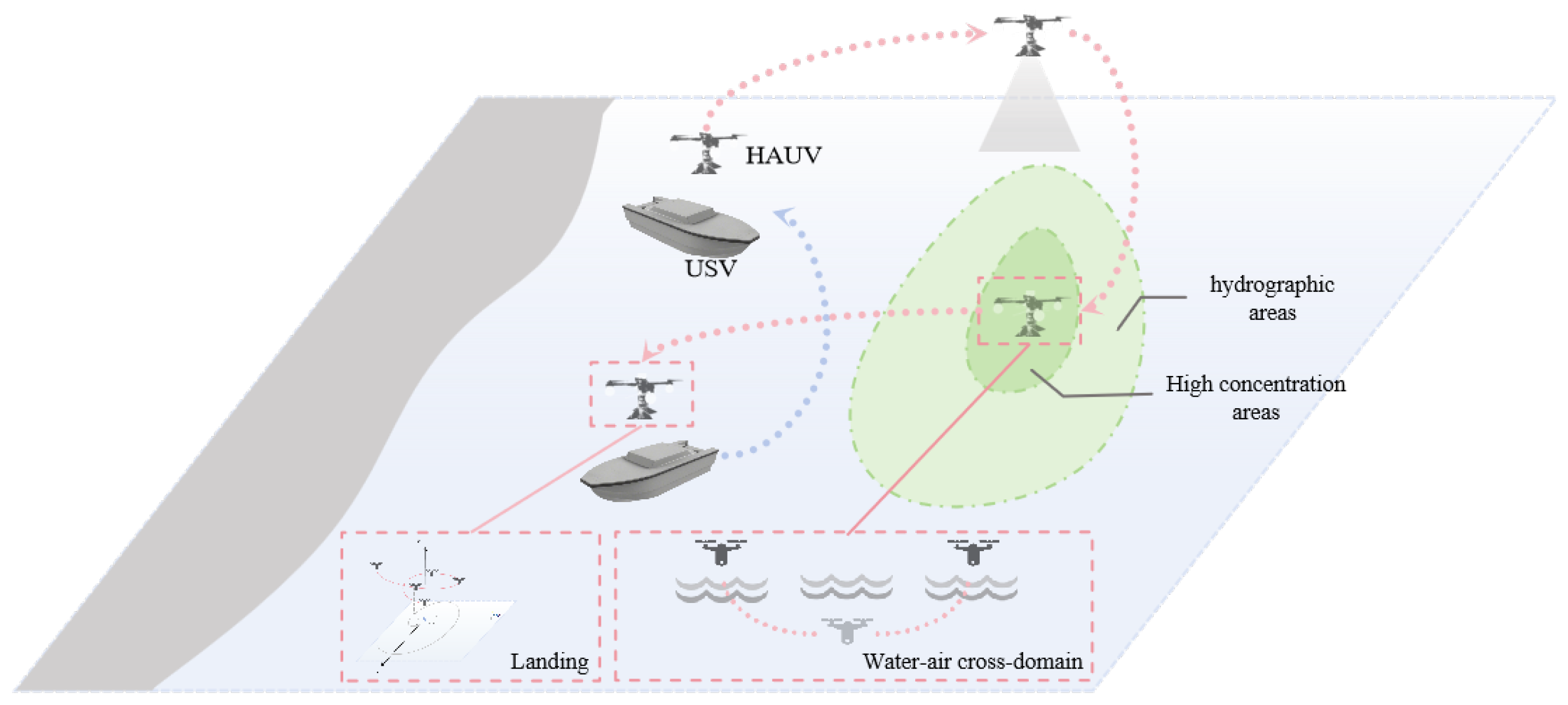
To achieve precise monitoring of marine hydrological parameters, this paper proposes a deeply integrated co-design of a multirotor hybrid aerial underwater vehicle with cross-domain capabilities and an unmanned surface vehicle [12,13]. This approach constructs an air–sea heterogeneous monitoring platform that leverages the complementary advantages of both systems (shown in Figure 2).
Within areas of expansive marine monitoring tasks, USVs provide basic platform support for HAUVs with their characteristics of long endurance and stable water platform. It assumes a core role in large-area cruising and the final integration and transmission of data. Sensors deployed on the USV primarily collect fundamental surface environmental parameters, such as sea surface temperature and salinity, and perform preliminary large-scale environmental scans.
When the task demands shift to monitoring the oceanographic vertical profile—such as detecting vertical temperature gradients, haloclines, or chlorophyll concentration profiles within the target sea area—the advantages of the collaborative system become evident [14]. Under commands from either the USV or a remote control center, the multirotor HAUV carried by the USV, equipped with sensors tailored to the requirements, autonomously takes off and proceeds to the designated task area or coordinates [15]. Leveraging its high-speed aerial maneuverability, it rapidly reaches the airspace above the predetermined monitoring point. It then executes the entire cross-domain hydrological profile monitoring mission, encompassing targeted submergence, underwater observation, surfacing, data transmission, and docking back onto the USV.
When continuous monitoring of underwater profiles at multiple distinct locations is required, the USV acts as a mobile base, transporting the HAUV to the vicinity of the next target area, where the aforementioned monitoring process is repeated cyclically [16]. This “Air–Sea–Air” cyclic operation mode is expected to address the current gap in existing HAUV-USV systems regarding the monitoring of marine hydrological vertical profiles, enabling comprehensive environmental perception from the water surface down into the water column.
It is crucial to emphasize that the system’s unique advantage over traditional monitoring methods lies in its capability for dynamic, large-scale, and multiparameter vertical profile monitoring, such as studying ocean stratification phenomena or pollutant dispersion. In such scenarios, conventional approaches prove inefficient. Therefore, the proposed HAUV-USV system does not aim to replace traditional methods but serves as a complementary solution, working alongside them to establish a “fixed-mobile” collaborative monitoring network. This integration combines the high temporal resolution of fixed buoys with the superior spatial and vertical resolution of mobile HAUV-USV systems, thereby achieving comprehensive and precise marine hydrological monitoring.
The HAUV-USV collaborative system faces new challenges, primarily in collaborative visual tracking and landing control. Addressing the complexities inherent in cross-domain collaboration, such as high-speed relative motion, strong surface reflection interference, and wave disturbances, is crucial. This paper presents a series of innovative contributions.
The remainder of this paper is structured as follows. Section 2 introduces the system architecture and cooperative control methods of the HAUV-USV heterogeneous platform. Section 3 details the dynamic modeling of the HAUV-USV heterogeneous platform, the relative motion model of the cooperative system, and key technologies such as collaborative tracking and cooperative landing. The experimental system, key experimental techniques, and validation procedures are presented in Section 4. Results and analyses are provided in Section 5, followed by conclusions and further discussions in Section 6.

2. HAUV-USV Collaborative System

The HAUV-USV platform constitutes a highly coupled heterogeneous autonomous system. As the unmanned surface vehicle and the hybrid aerial underwater vehicle represent distinct types of platforms, significant differences exist in their respective structural compositions, kinematic and dynamic models, and control methodologies [17,18]. Consequently, research into the structural configuration of both the USV and the HAUV, along with the system architecture and collaborative control technologies of this heterogeneous platform, is essential.
This section first introduces the collaborative system architecture of the HAUV-USV platform. The subsequent subsections elaborate on the structural composition of the amphibious UAV and the unmanned surface vessel individually. Finally, it provides a detailed description of the collaborative control methodology employed by the heterogeneous system.

2.1. Architecture of the HAUV-USV Collaborative System

The HAUV-USV collaborative system adopts a distributed architecture to achieve a full-process coordination of sea–air cross-domain monitoring missions. The system employs the unmanned surface vehicle as a mobile base and data hub, and the hybrid aerial underwater vehicle as a front-end detection unit. By establishing heterogeneous interconnection, it forms a dynamic platform–mobile sensor cooperative framework [19]. As illustrated in the accompanying figure, the overall architecture adheres to core principles of modularity and scalability, supporting adaptive reconfiguration for different mission scenarios.
To address the computational demands of the Model Predictive Control algorithm, particularly the intensive optimization processes such as receding horizon optimization and constraint solving, a distributed computing architecture is adopted in the collaborative control system. The USV, as a mobile base with sufficient payload capacity and stable power supply, is equipped with a high-performance embedded processor NVIDIA Jetson to handle these computationally heavy tasks. This processor, integrated within the USV’s central control compartment, executes the MPC optimization in real time, generating optimal control increments that account for marine disturbances.
This protocol supports bidirectional data exchange, allowing the NVIDIA Jetson to send optimized control instructions to the Pixhawk, while the Pixhawk feeds back real-time state data of the HAUV to the high-level planner, forming a closed-loop control chain (shown in Figure 3).

2.2. Structural Composition of the HAUV Platform

2.2.1. Primary Structural Framework

The multirotor hybrid aerial underwater vehicle employs a modular composite structure. Its primary frame predominantly utilizes carbon fiber-reinforced resin matrix composites and an acrylic-sealed main compartment, balancing lightweight properties with corrosion resistance. The upper section houses the flight control compartment, integrating the flight control system and power module. The lower section constitutes the underwater operational compartment, featuring a pressure-resistant spherical enclosure with a streamlined aerodynamic profile to minimize flight drag. This compartment withstands hydrostatic pressure equivalent to a depth of 100 m and is coated with a hydrophobic surface material to reduce hydrodynamic resistance during water entry. Detachable buoyancy modules, fabricated from closed-cell foam, are mounted at the rotor arm termini to provide ascent buoyancy post-submersion operations. A servo-actuated release mechanism installed beneath the main frame jettisons ballast weights upon reaching the predetermined operating depth, enabling controlled resurfacing.
To further validate the structural design and cross-domain mobility, we conducted field tests in a coastal shallow water area. During the tests, the HAUV successfully completed a full cycle of operations: taking off from the shore, flying to the designated offshore area, submerging into the water (reaching a maximum depth of 5 m), hovering underwater for 3 min, surfacing, and returning to the starting point. These tests directly demonstrated the reliability of the hardware integration—including the pressure-resistant compartment, buoyancy adjustment system, and cross-domain propulsion unit—and verified the basic feasibility of its air–water–air motion transitions in a near-shore marine environment.
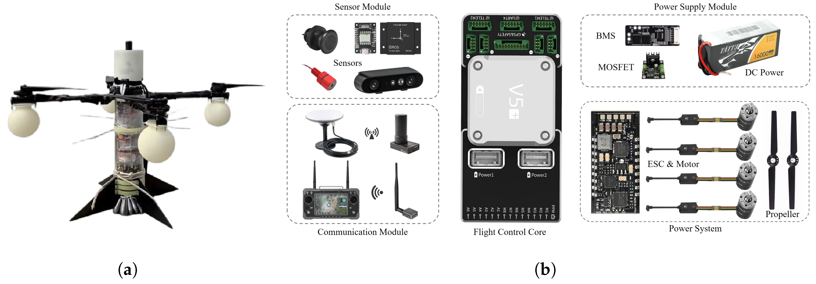
The HAUV control system primarily adopts a distributed architecture, comprising the following components: a central control unit, data acquisition devices, communication modules, power management systems, and propulsion subsystems (shown in Figure 4). The ground station utilizes a remote controller to transmit real-time commands to the HAUV’s central unit via wireless radio transmission protocols. Prior to take-off, the amphibious HAUV’s operational depth profile is preconfigured; alternatively, it autonomously ascends upon detecting a predefined clearance from the seabed during missions [20]. The master control computer executes overall mobility control and manages measurement/storage of marine sensor data. By processing real-time navigation aid metrics (position, attitude), it dynamically identifies the current media environment (air/water) and operational phase of the mobility profile. This enables autonomous transitions between surface/submerged locomotion modes, as well as water–air/air–water media-crossing sequences.
This study employs the Pixhawk open-source control board—noted for its operational stability and ease of secondary development—as the core of the surface mobility control module for the amphibious vehicle. The board exhibits robust data processing capabilities, integrates multiple essential motion sensor modules, and provides extensive peripheral interfaces for expandability. It further enables bidirectional communication with ground stations via the MAVLink protocol. The ground segment centers on a computer running QGroundControl (QGC), an open-source ground station software. This platform facilitates mission trajectory planning, real-time monitoring, and—during indoor testing—direct real-time motion command input through connected joysticks. For field operations, multiple communication modalities exist between the onboard Pixhawk and ground station, including WiFi modules and telemetry radios. The system prioritizes telemetry radios for their greater range, enhanced stability, and superior field adaptability in amphibious vehicle deployments.

2.2.2. Cross-Domain Propulsion System

To achieve stable cross-domain transitions (air–water–air) for the HAUV, this study employs an advanced transition methodology. During water entry, the vehicle’s attitude and velocity are precisely controlled to ensure optimal angle of attack and contact speed with the water surface, thereby preventing air–propeller–water impact. Concurrently, externally mounted buoyancy modules stabilize surface flotation, followed by rapid submersion via ballast weight deployment. For water-to-air transitions, the buoyancy control system enables finely tuned adjustments, allowing the vehicle to exit the water at a stabilized velocity and attitude before switching seamlessly to flight mode. To guarantee transition continuity and stability, the propulsion and control systems incorporate failover mechanisms that maintain consistent power output and control authority during media shifts. Detailed designs of the cross-domain control system are presented in Section 3.1.2.

2.2.3. Sensing Mechanism

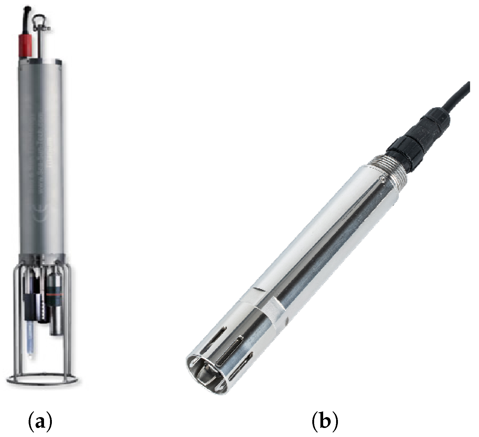
The HAUV incorporates a modular payload bay at its base, enabling flexible deployment of diverse marine monitoring sensors (shown in Figure 5). This sensor compartment utilizes an acrylic spherical pressure-resistant housing rated for pressures up to 1.5 MPa (equivalent to 100 m depth), supporting simultaneous operation of optical and acoustic sensors. The payload bay features an RS-485 standard communication interface at its apex, integrating a 24 V power bus and USB 3.0 data port to ensure real-time data exchange between sensors and the vehicle’s central control system.
Sensors implement an adaptive sampling strategy that dynamically adjusts acquisition frequency based on marine environmental gradients. When the vehicle submerges to predetermined depth intervals, the sampling rate escalates to achieve high-density vertical gradient data collection. The HAUV’s embedded high-precision inertial measurement unit (IMU) employs control algorithms to compensate for positional deviations in sampling locations induced by vertical motion dynamics.

2.3. Structural Composition of the USV Platform

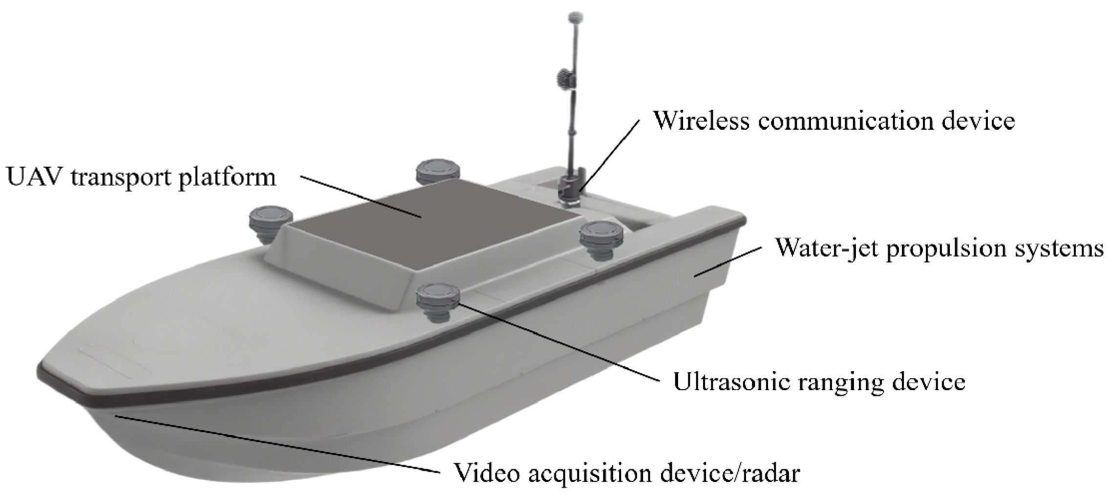
The unmanned surface vehicle platform serves as the foundational infrastructure for the heterogeneous collaborative monitoring system. Its structural composition is meticulously engineered to fulfill requirements for extended endurance, stable operations, and cross-domain coordination (shown in Figure 6).
The primary structure employs a monolithic pressure-resistant hull integrated with an electric propulsion system to sustain prolonged surface cruising capabilities [21]. Within the hull, a central control compartment houses a data processing server and satellite communication module, enabling real-time environmental data integration and remote transmission. The sub-hull section accommodates a configurable standardized sensor array, including instruments such as sea surface temperature/salinity detectors and multiparameter water quality probes for acquiring fundamental surface environmental parameters [22]. Concurrently, a sonar system facilitates shallow subsurface environmental scanning. The modular architecture of the USV is illustrated in the accompanying figure.
The overall design prioritizes a low-center-of-gravity configuration and optimized weight distribution, conferring multiple operational advantages [23]. On one hand, the low-center-of-gravity structure significantly enhances hull stability in complex sea states. Even when subjected to wave impacts or strong wind disturbances, it effectively mitigates roll and pitch amplitudes, ensuring stable operation of both the deck-mounted sensor array and the HAUV docking platform. On the other hand, this design reduces acoustic interference caused by hull heave motion on sonar systems, thereby improving the accuracy of acoustic data acquisition during shallow subsurface environmental scans. Simultaneously, it provides a more stable reference plane for HAUV take-off and landing operations, enhancing the reliability of cross-domain collaborative missions.
The pivotal innovation resides in the HAUV docking platform at the vessel’s deck center. This platform incorporates a landing pad imprinted with fiducial markers for visual guidance. Leveraging a landing guidance algorithm, it enables HAUV trajectory pre-planning through visual recognition, providing multirotor amphibious drones with a cross-domain docking surface that ensures both stabilized positioning and decimeter accuracy.
Furthermore, the design allocates space for an integrated charging dock and modular payload bay. This facilitates rapid post-recovery energy replenishment and sensor reconfiguration—for example, swapping dissolved oxygen probes for underwater cameras—establishing the foundation for a unified monitoring framework where USV and HAUV systems operate synergistically, complementing each other’s capabilities.

2.4. HAUV-USV Collaborative Control System

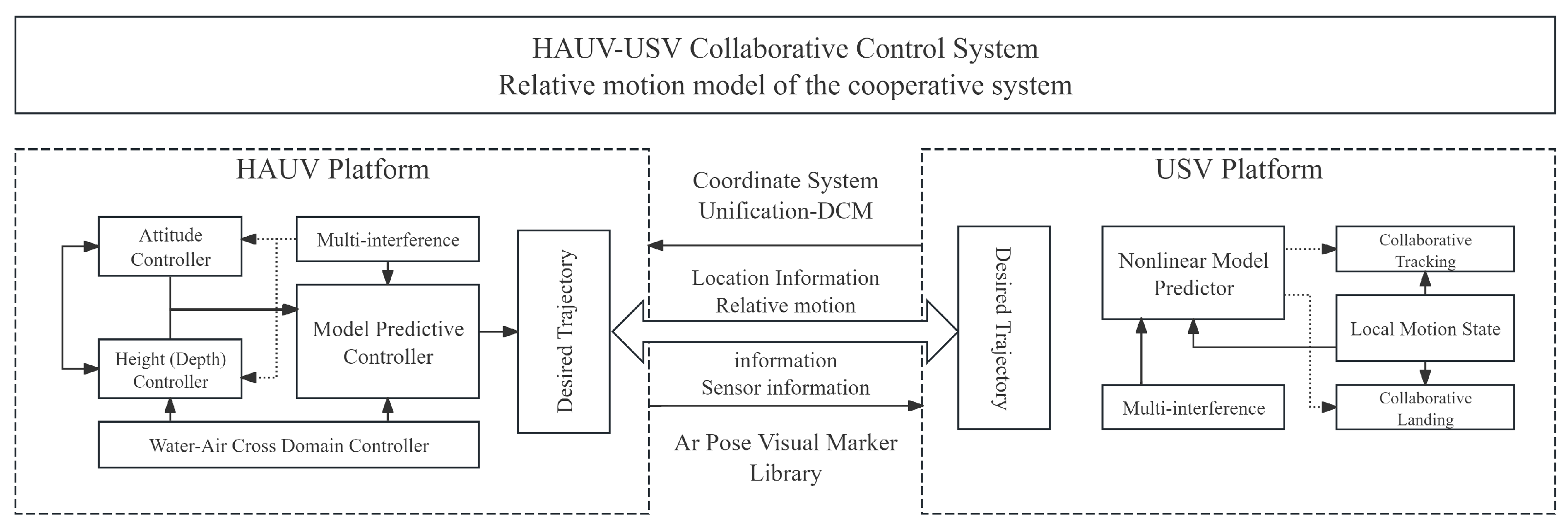
To achieve collaborative integration of the HAUV and USV systems while ensuring proximity tracking accuracy and landing recognition precision, a relative motion model of the cooperative system must be established [24]. The architecture of the collaborative control system is illustrated in the block diagram below (shown in Figure 7).
The underwater operation mode of the Autonomous Submersible Vehicle operates through a “predefined task + autonomous execution” mechanism, eliminating the need for real-time communication with the surface unmanned underwater vehicle. During surface operations, the USV sends predefined task instructions to HAUV, specifying target monitoring points, depth ranges, and sampling parameters. After deployment, HAUV autonomously completes vertical profile monitoring (including temperature and salinity gradient data collection) according to pre-programmed procedures, with all data temporarily stored in onboard storage modules. Upon completing underwater tasks and surfacing, HAUV wirelessly transmits data back to the USV while updating its operational commands.
First, coordinate system unification is accomplished through transformations: Position data from the USV’s local coordinate system is converted into the HAUV’s navigation frame via a Direction Cosine Matrix (DCM) using Euler angle rotation matrices. Leveraging the Ar Pose visual marker library within the Robot Operating System (ROS) framework, camera and body-fixed coordinate systems are aligned to achieve position offset compensation across heterogeneous platforms.
Subsequently, for collaborative tracking control, a Model Predictive Control (MPC) algorithm addresses multi-constrained challenges under marine wind–wave–current disturbances [25,26]. This approach formulates the linearized HAUV mathematical model into a discrete state-space representation, solving for optimal control increments through receding horizon optimization to enable real-time HAUV trajectory tracking relative to the USV’s reference path.
Finally, during collaborative landing control, computer vision positioning ensures continuous alignment above the landing marker’s centroid. This integrates with onboard attitude predictors estimating the USV’s orientation angles [27]. A phase-split control strategy dynamically adjusts landing maneuvers to counteract wave-induced vessel motions, achieving pinpoint autonomous docking despite hydrodynamic perturbations. Detailed system control methodologies are presented in Section 3.

3. Main Method

3.1. Dynamic Modeling of the Heterogeneous HAUV-USV Platform

3.1.1. Dynamic Modeling of the HAUV

A hybrid aerial underwater vehicle is a composite unmanned system integrating aerial flight and aquatic locomotion capabilities [28]. Its kinematic model must simultaneously account for aerodynamic dynamics during flight, hydrodynamic behaviors during underwater operations, and kinetic characteristics during mode transitions.
In aerial flight mode, the HAUV adheres to conventional multirotor aerodynamics, enabling six-degree-of-freedom (6-DOF) motion. Within the body-fixed coordinate system, the relationship between angular acceleration and torque is governed by
J ω ˙ = ω × ( J ω ) + τ total
where J denotes the inertia tensor matrix, the angular velocity ω = [ p , q , r ] T R 3 with p, q, and r representing the roll rate, pitch rate, and yaw rate, respectively. The resultant torque vector τ total is generated by differential rotor speeds.
Taking this HAUV’s quadrotor configuration as an example, the relationship between torques and rotor thrusts is expressed as
τ ϕ = l · ( T 2 T 4 ) τ θ = l · ( T 3 T 1 ) τ ψ = k · ( T 1 + T 3 T 2 T 4 )
where l denotes the distance from rotor axis to center of mass, k represents the yaw torque coefficient, and T 1 , T 2 , T 3 , T 4 correspond to the thrust outputs of individual rotors.
Furthermore, given that the HAUV’s center of gravity lies beneath the rotor plane in this configuration, attitude variations generate additional torque due to the offset between the gravity vector and the rotor plane center [29]. In dynamic control design, this torque must be incorporated as a feedforward compensation term to enhance system stability. When the acceleration vector a = a x , a y , a z acts on the system, the compensation torque is given by
M i = r C G × F i = i b j b k b 0 0 h m a x m a y m a z = m · h · a y i b a x j b
where r C G = ( 0 , 0 , h ) denotes the position vector of the center of gravity relative to the origin O b of the body-fixed frame.
The HAUV operates in littoral zones, allowing the hydrodynamic modeling to disregard seawater density variations and depth-induced pressure hull deformation effects. The underwater dynamics model is expressed as follows:
m z ¨ = m g ρ water V g 1 2 C d z ρ water A z ˙ | z ˙ |
where C d z denotes the vertical drag coefficient of the unmanned vehicle in water, and A represents the projected area along the z-axis.
The current underwater hydrodynamic model primarily focuses on vertical dynamics, considering gravity, buoyancy, and drag forces in the z-axis. However, it simplifies several complex hydrodynamic factors: horizontal forces such as added mass forces and vortex-induced forces are not explicitly modeled, and dynamic effects of salinity and temperature on seawater density are omitted.
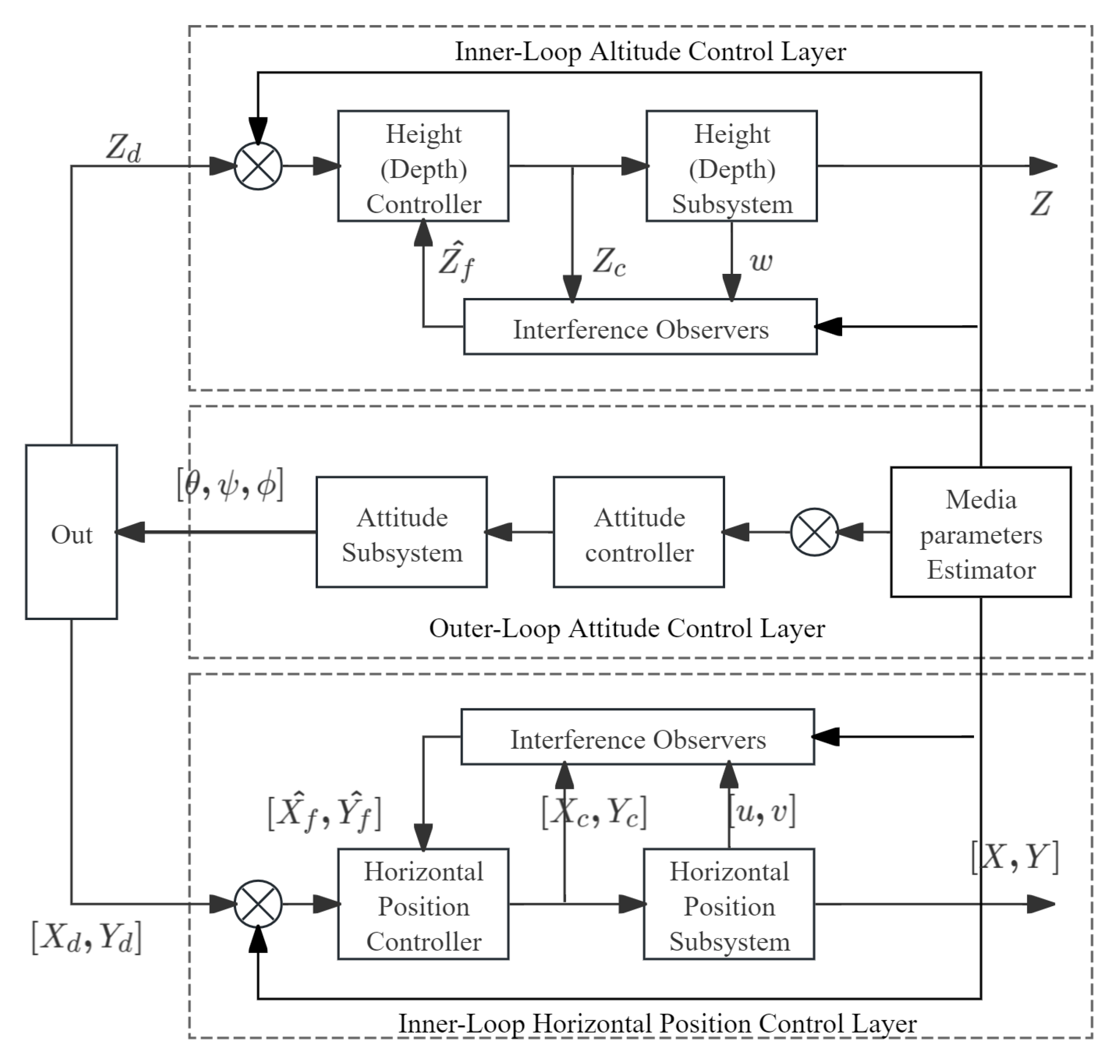
During HAUV’s cross-domain vertical transitions, its dynamic model exhibits significant complexity. To address this, a stepwise low-velocity water–air transition is achieved by constraining the inner-loop horizontal/altitude trajectory controllers and outer-loop attitude controllers within defined temporal windows.
As illustrated in Figure 8, the outer-loop trajectory control layer synthesizes attitude data to generate commands for inner-loop controllers. The inner-loop altitude control layer employs an altitude subsystem and altitude controller, augmented by a nonlinear altitude disturbance observer, to regulate vertical position and ensure precise altitude tracking. Concurrently, the horizontal position control layer executes planar trajectory tracking.
The HAUV’s autonomous decision-making and execution capabilities throughout the air–water transition mission cycle are enabled by its integrated sensing and control system. The central control unit, as part of the distributed architecture, continuously fuses data from the high-precision inertial measurement unit, pressure sensors, and a media recognition algorithm to determine in real time the current operating environment and motion phase.
A medium parameter estimator bridges outer and inner control loops, estimating underwater medium parameters to compensate for hydrodynamic disturbances and enhance control robustness. This hierarchical architecture “outer-loop planning, inner-loop execution, disturbance compensation” enables decoupled control layers that accurately track desired trajectories while counteracting complex hydrodynamic disturbances during media transitions.

3.1.2. Dynamic Modeling of the USV

A complete six-degree-of-freedom (6-DOF) kinematic model can describe the motion states of an unmanned surface vehicle across all six degrees of freedom. However, given that the USV exhibits minimal motion amplitudes in heave, pitch, and roll during practical operations, these three degrees of freedom are typically neglected. This simplification yields a reduced three-degree-of-freedom (3-DOF) kinematic model, focusing exclusively on surge, sway, and yaw motions. Such simplification enhances practicality for motion analysis and controller design in real-world applications. The resulting simplified USV dynamic model is expressed as
X ˙ S Y ˙ S ψ ˙ S = cos ψ S sin ψ S 0 sin ψ S cos ψ S 0 0 0 1 u S v S r S
where ψ S denotes the heading angle of the USV.

3.2. Relative Motion Model of the Collaborative System

To achieve collaborative integration between the USV and HAUV systems while ensuring precise relative tracking motion and landing recognition accuracy, the real-time acquisition of the HAUV’s relative kinematic states—including position, attitude, velocity, and other motion parameters—is critical. Through transformations of the coordinate system on these heterogeneous platforms, collaborative motion state information is acquired. Leveraging these motion data, this study implements collaborative tracking and autonomous landing control relative to the USV platform.

3.2.1. Coordinate System Transformation and Vision-Based Spatial Data Acquisition

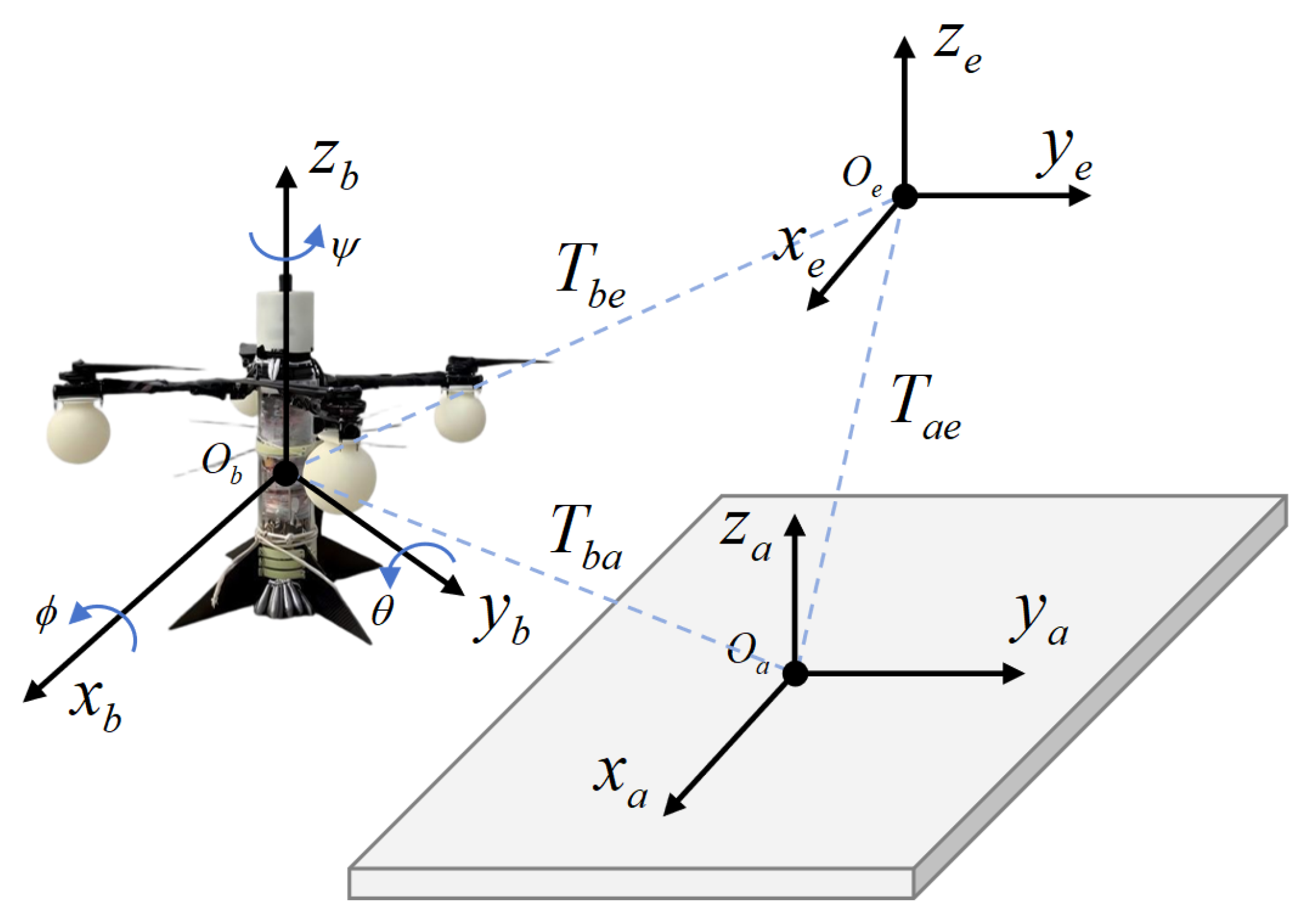
Utilizing the spatial relative distance and positioning principles between the unmanned surface vehicle and the unmanned aerial vehicle, mobile guidance is implemented to achieve precise positioning and control of the HAUV. Specifically, to obtain accurate relative positions of the HAUV, coordinate transformations from disparate systems must be unified to the body-fixed frame, with real-time compensation applied for position offsets induced by USV motion [30]. The corresponding coordinate transformations and position offset compensation between the USV and HAUV are illustrated as Figure 9.
Using positional data provided by the unmanned surface vehicle guidance system, the hybrid aerial underwater vehicle initiates trajectory tracking from its initial position O b , ultimately landing at the centroid of the USV’s deck O a . To facilitate subsequent kinematic modeling, the USV’s local coordinate position vector R b is transformed into the HAUV’s navigation coordinate frame R e through a Direction Cosine Matrix (DCM) operation.
R e = R s · R b
where R s denotes the Euler angle rotation matrix, also referred to as the attitude matrix or roll matrix.
R s ( ϕ , θ , ψ ) = R z ( ψ ) · R y ( θ ) · R x ( ϕ )
R s = c ψ c θ s ψ c ϕ + c ψ s θ s ϕ s ψ s ϕ + c ψ s θ c ϕ s ψ c θ c ψ c ϕ + s ψ s θ s ϕ c ψ s ϕ + s ψ s θ c ϕ s θ c θ s ϕ c θ c ϕ
The Ar Pose pose estimation library is a vision library within the Robot Operating System (ROS) framework for target recognition and pose estimation. By employing the Ar Pose package, communication between the onboard camera and Ar Pose nodes is established to determine the spatial information of detected fiducial markers, thereby enabling calculation of the HAUV’s coordinates. In this study, fiducial markers are utilized as identification targets, with the camera coordinate system O v configured to align with the body-fixed frame O b .

3.2.2. HAUV-USV Collaborative Tracking Control

During collaborative missions between the hybrid amphibious unmanned vehicle and unmanned surface vehicle, real-time tracking of the USV by the amphibious UAV must be achieved. Given that both systems are subject to wind–wave–current disturbances in marine environments, HAUV tracking of the USV requires significantly more constrained conditions compared to land-based UAV tracking scenarios [31]. For such multi-constrained tracking control problems, Model Predictive Control (MPC) demonstrates superior performance. This paper designs an MPC-based collaborative HAUV-USV tracking control architecture, as illustrated in the block diagram below (shown in Figure 10).
When the HAUV’s tracking of the USV, the USV continuously transmits its motion trajectory Y r e f = X S , Y S , Z S T . The HAUV adjusts its spatial position in real time based on the received trajectory data to accomplish tracking tasks. The linearized mathematical model of the unmanned aerial vehicle is expressed in discrete state-space form as follows:
x a ( k + 1 ) = A a x a ( k ) + B a u a ( k ) y a ( k + 1 ) = C a x a ( k + 1 )
where A a , B a , and C a represent the state matrix, input matrix, and output matrix of the HAUV system, respectively. To integrate state deviations with output trajectories, an augmented state vector is constructed as x ^ a ( k ) = Δ x a ( k ) T , y a ( k ) T T . This model enables the prediction of future state and output variables at time step k.
The Model Predictive Control algorithm achieves real-time tracking through receding horizon optimization. At each time step k, the control input for the HAUV is computed to minimize deviations between the predicted outputs and the USV’s reference trajectory. The cost function J governing the entire HAUV tracking process is defined as
J = Y Y r e f T Q Y Y r e f + Δ U a T R Δ U a
where Q denotes the weighting matrix for tracking errors, while R represents the weighting matrix for control effort penalties.
To achieve precise HAUV tracking of the USV, a high Q-value and low R-value must be selected. The tracking error weight matrix Q is a diagonal matrix that sets weights for the position tracking errors in the ( x , y , z ) directions of the HAUV. Q = d i a g ( 100 , 100 , 200 ) , where the z-direction (height/depth) weight is higher, prioritizing vertical tracking accuracy, which is crucial for stability during subsequent landing phases. The control input weight matrix R is also a diagonal matrix that sets weights for the control inputs of the HAUV. Specifically, R = d i a g ( 0.1 , 0.1 , 0.1 , 0.1 ) .
The simplified hydrodynamic model may reduce the prediction accuracy of the MPC algorithm, particularly in strong currents or complex flow fields. Unmodeled horizontal hydrodynamic disturbances, such as lateral vortices, can introduce additional tracking errors. However, the current framework mitigates this limitation through dynamic adjustments of the error weighting matrix Q by increasing the weights on horizontal position errors in the cost function. The MPC algorithm prioritizes compensation for unmodeled disturbances, maintaining acceptable tracking accuracy in low-to-moderate disturbance scenarios. This balance between model complexity and control performance ensures the algorithm remains practical for the initial validation of the collaborative system.
To determine the optimal value of the cost function, the partial derivative of J is taken, and the optimal control sequence Δ U a is substituted back into J. Thus, minimizing the cost function transforms into solving for the optimal Δ U a . To resolve this convex optimization problem, a Lagrange multiplier λ is introduced, yielding the following Lagrange expression:
L = 1 2 Δ U a T E Δ U a + Δ U a T F + λ T M a U a γ
Solving the equation yields Δ U a = E 1 M a T λ + F . The optimal control input increment for the system can then be obtained by solving for the value that optimizes this expression.

3.2.3. HAUV-USV Collaborative Landing Control

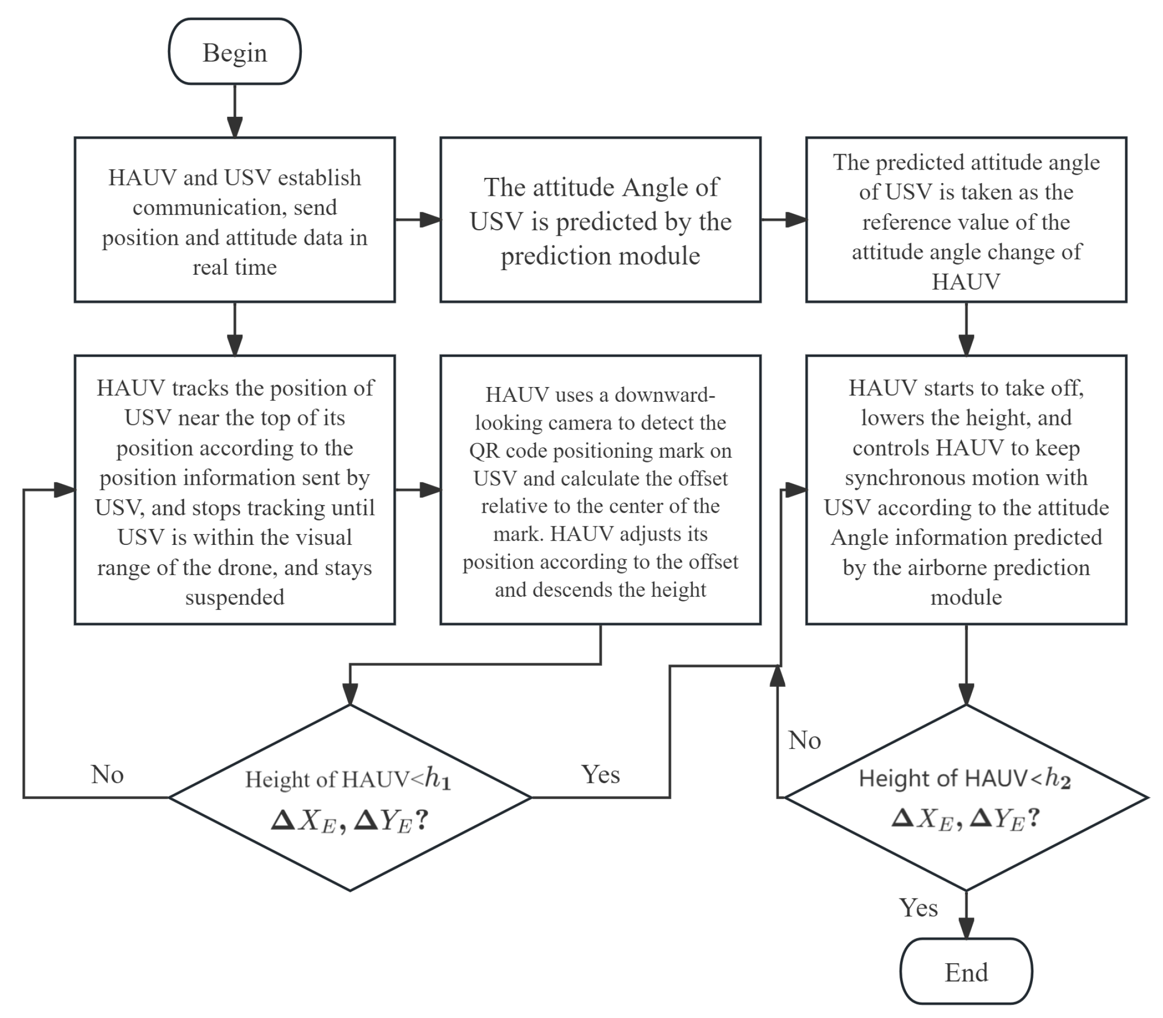
The framework for the precision landing method based on synchronous motion is illustrated in the Figure 11 below. This method employs computer vision-based positioning to ensure the HAUV remains proximate to the centroid of the landing marker throughout the docking process [32,33]. Concurrently, an onboard attitude predictor forecasts the USV’s orientation angles, enabling real-time compensation for vessel attitude variations. Ultimately, this achieves decimeter-level landing accuracy under dynamic marine conditions.
Effective collaborative control between HAUV and USV requires the landing marker to remain within the field of view of the HAUV’s downward-facing camera throughout the landing process. When the HAUV altitude descends below threshold h 1 , the drone utilizes predicted USV attitude angles as reference signals to dynamically synchronize with the vessel’s motion. Simultaneously, the HAUV actively minimizes its directional deviation from the center of the marker to ensure landing alignment. Upon meeting dual conditions—directional deviation falling below a preset threshold and altitude reducing below threshold h 1 —the vertical descent velocity v z is instantaneously ramped up to v m . This acceleration phase continues until landing on the USV deck is achieved.

4. Experiments

4.1. HAUV-USV Collaborative Tracking Simulation Experiment

The simulation analysis is based on Matlab. The specific simulation environment is as follows: 64-bit Windows 10 system, Matlab 2019b, Intel (R) Core (TM) i5-13400 processor, NVIDIA RTX 4060 Ti graphics card, and 16 GB of RAM. The UAV model parameters in the simulation system are provided by the RflySim software, developed by the Reliable Flight Control Research Group at Beihang University.
The model-based predictive control strategy designed in this chapter is used to simulate and analyze the trajectory tracking of unmanned boats and drones. In the simulation experiment, the unmanned boat starts from the origin and sequentially reaches four designated task points. During its journey, the unmanned boat sends its position updates to the drone, which then performs real-time predictive tracking of its trajectory.

4.2. HAUV-USV Collaborative Landing Simulation Experiment

The simulation platform was constructed on an Ubuntu 20.04 operating system, utilizing the ROS framework and Gazebo physics engine. The UAV simulation environment integrated an AR Drone quadrotor model controlled via the tum-simulator package, while the USV platform employed the Kingfisher-USV model from ROS as the landing vessel [34,35].
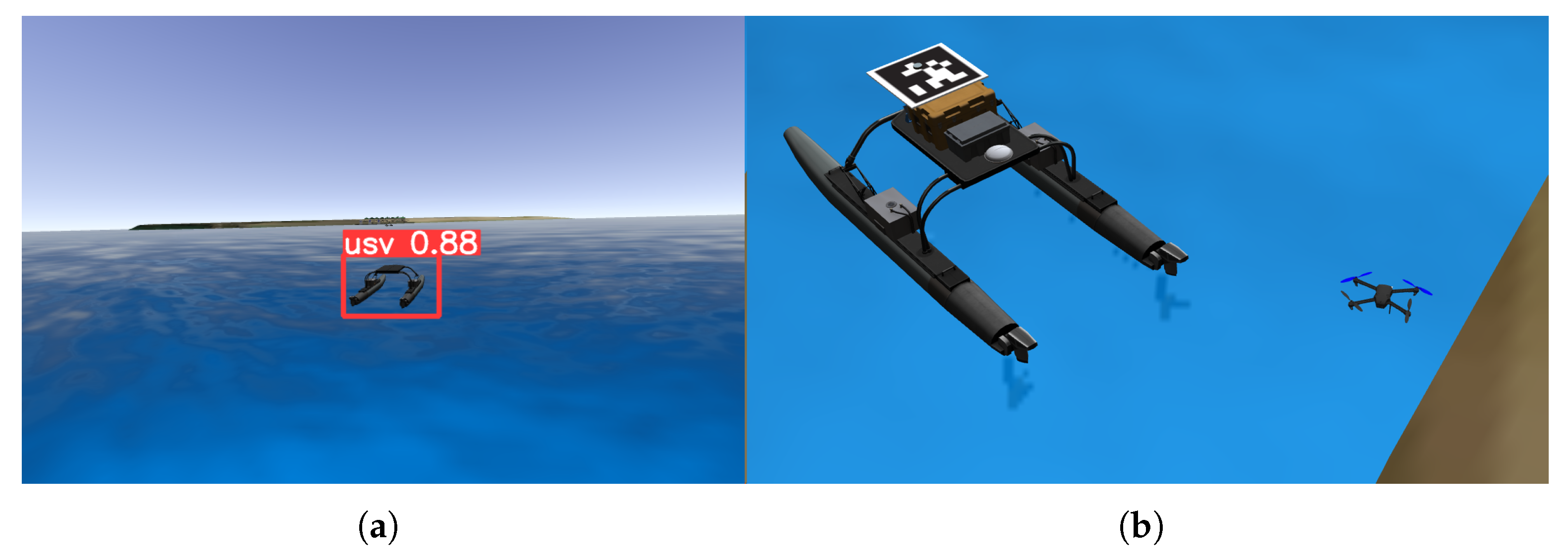
This chapter employs the Ar Pose estimation library for precise recognition and localization of landing markers, with a specifically designed Ar Pose fiducial marker serving as the visual target as illustrated in the accompanying figure (Figure 12).
This experiment primarily investigates the landing of drones on unmanned ships under conditions of interference. In this scenario, the yaw movement of the unmanned ship is greater than its pitch movement, and the ship mainly moves along the Y A direction. The number of experiments conducted for the unmanned ship’s pitch movement is the same as for the yaw movement, with 10 synchronized landing experiments and 10 conventional landing experiments performed, and a comparative analysis of the landing accuracy is conducted.

5. Results and Analysis

5.1. Result of HAUV-USV Collaborative Tracking Simulation Experiment

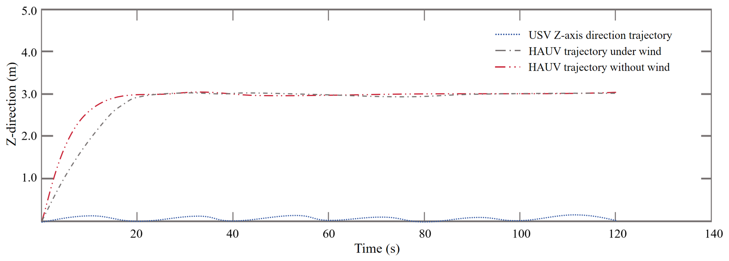
After determining the optimal control horizon and prediction horizon, environmental disturbances were introduced into the simulation system with a crosswind speed of 5 m/s.
Wind speed is a critical environmental factor affecting the attitude stability and landing accuracy of cross-domain aircraft. The simulation data provide quantitative references for wind-resistant system design, indirectly reflecting the system’s initial adaptability to ocean surface dynamic disturbances. The verification of key environmental parameters in wind speed simulations offers essential feasibility evidence for transitioning from digital models to physical prototypes. Under these conditions, simulation experiments analyzed the HAUV’s altitude tracking performance at 3 m and its tracking of the USV trajectory. As illustrated in the Figure 13 below, the HAUV maintains stable positioning at the commanded altitude of 3 m despite wind disturbances. While exhibiting confined fluctuations, it consistently satisfies all constraints while tracking the USV. These results demonstrate that the proposed MPC-based cooperative tracking control algorithm effectively enables real-time HAUV pursuit of the USV under dynamic environmental conditions.
By implementing output constraints, this study prevents the HAUV from tracking the heave motion components of the USV trajectory, enabling stable trajectory pursuit under environmental disturbances. The simulation results demonstrate that the receding horizon optimization characteristic of the MPC algorithm effectively handles uncertainties induced by wind, waves, and currents. Through a cost function that incorporates tracking error weighting and control effort weighting, the algorithm achieves a superior balance between tracking precision and control stability. Its exceptional performance in vertical motion control particularly validates the ability of the strategy to suppress disturbances in the altitude dimension.
To further validate the system’s robustness in more complex marine environments, future research will expand the simulation scenarios by introducing three additional types of disturbance-specific verification: (1) Current interference simulation: This involves modeling both steady and pulsating ocean currents to evaluate trajectory deviation of HAUVs during underwater vertical profile monitoring and the trajectory stabilization capability of USVs. (2) Pitch motion testing: The system sets pitch angle ranges for USVs under wave action to verify the attitude prediction module’s adaptability to severe pitching motions. (3) Wind disturbance simulation: the wind speed in simulations is increased from 5 m/s to near-shore strong wind levels, assessing the MPC algorithm’s effectiveness in suppressing intense wind disturbances.

5.2. Result of HAUV-USV Collaborative Landing Simulation Experiment

Validation experiments confirm that the proposed synchronous landing methodology outperforms conventional approaches in landing accuracy, indicating its suitability for precise autonomous docking in complex marine environments.
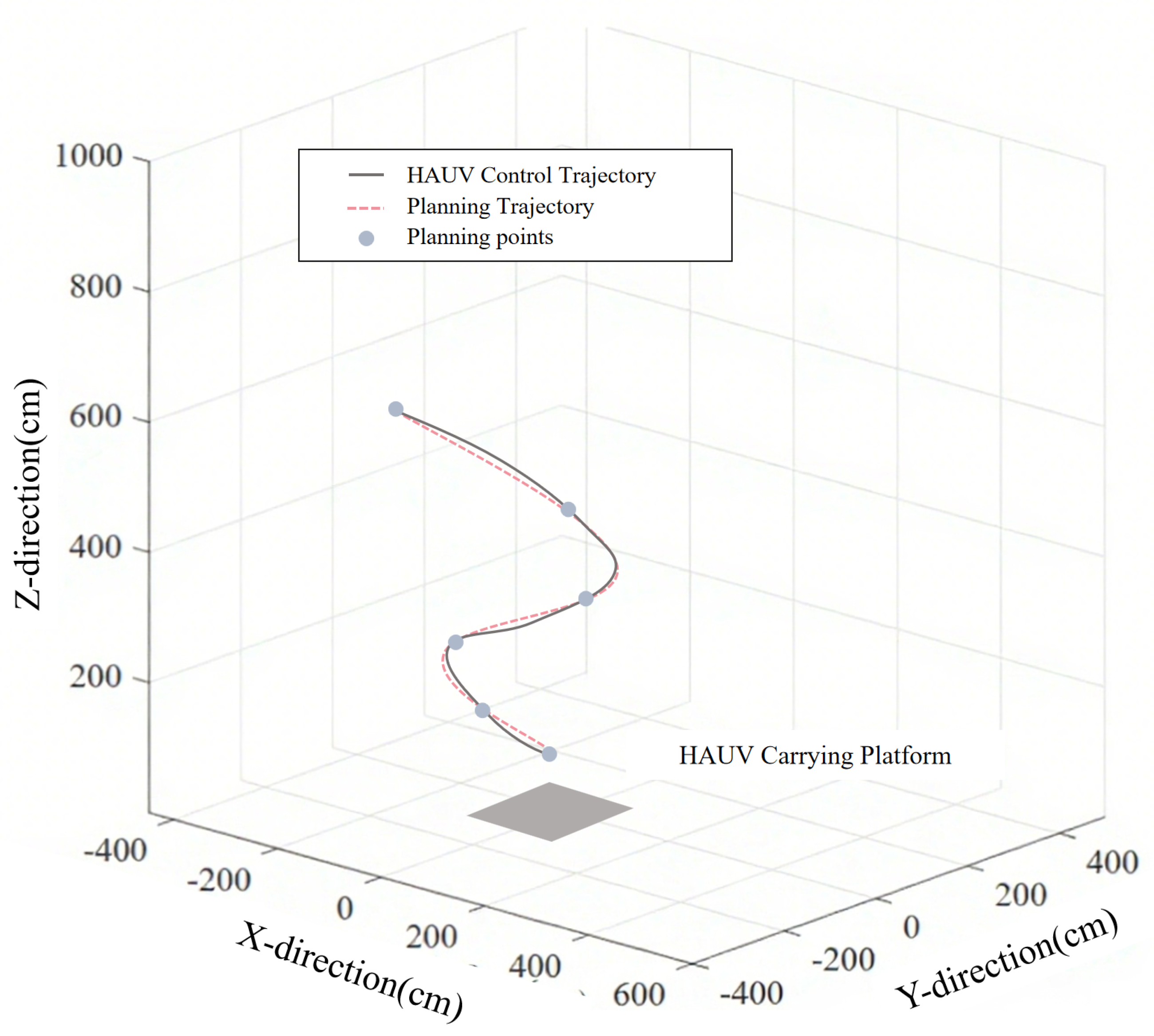
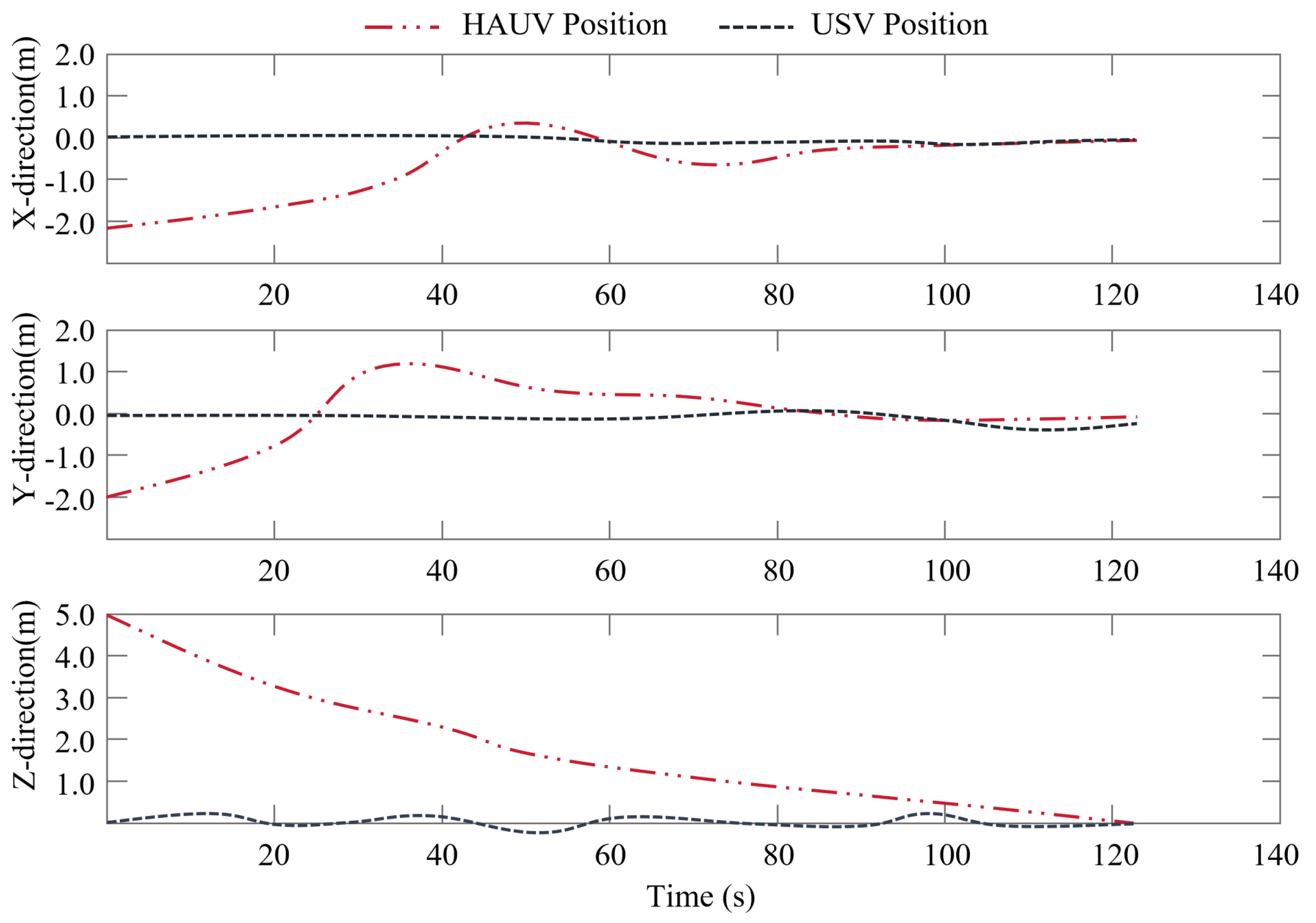
Within the ROS-Gazebo simulation platform, the comparative analysis reveals that when the USV experiences roll-dominant disturbances, the synchronous control strategy reduces landing position error across 10 trials (shown in Figure 14). Additionally, the HAUV maintains alignment above the centroid marker, indicating the efficacy of the vision-based positioning and attitude prediction synchronization framework (as shown in Figure 15).
The MPC-based cooperative tracking algorithm and the phased landing control strategy demonstrate robust feasibility in challenging ocean conditions through simulations. This system provides theoretical foundations for real-world HAUV-USV operations, ensuring tracking accuracy and landing safety even under wave disturbances. Future work will optimize control parameters with field test data to improve extreme environment robustness.

6. Conclusions

This study establishes a deeply integrated heterogeneous monitoring platform through the co-design of a hybrid aerial underwater vehicle and an unmanned surface vehicle, effectively bridging the functional gap in marine hydrological vertical profile monitoring. The proposed system leverages the complementary capabilities of both platforms: the USV serves as a long-endurance mobile base for surface operations and data integration, while the HAUV executes rapid cross-domain transitions for high-resolution vertical gradient sensing across air–water interfaces. A distributed “Air–Sea–Air” cyclic operational architecture enables comprehensive environmental perception from surface to subsurface layers, supporting repeated missions such as temperature/salinity profiling and chlorophyll concentration mapping.
Key innovations include the development of a coupled HAUV-USV dynamic model that incorporates aerodynamic/hydrodynamic interactions during media transitions, alongside an MPC-based collaborative tracking algorithm that maintains real-time trajectory pursuit under marine disturbances. Experimental validation confirmed that the receding horizon optimization strategy effectively constrained tracking errors while balancing control stability and precision. Furthermore, a vision-guided synchronous landing methodology integrating Ar Pose marker localization and USV attitude prediction achieved decimeter-level docking accuracy under dynamic sea conditions.
While simulation results verify the system’s robustness in trajectory tracking and wave-rejection capabilities, future work will address system reliability in corrosive marine environments, increase lightweight acoustic modules to demonstrate the potential advantages of underwater communication for system synergy, and extend the framework to multi-HAUV coordination scenarios. Field validation in open-ocean environments remains essential to evaluate performance under extreme hydrodynamic conditions. This work ultimately provides a foundational paradigm for autonomous, scalable oceanographic observation systems capable of capturing critical vertical gradient parameters previously inaccessible to conventional monitoring platforms.
Author Contributions

Conceptualization, Q.W. and Z.Y.; methodology, Q.W. and S.H.; software, Q.W.; validation, Q.W., Z.Y. and G.W.; formal analysis, Q.W.; investigation, Z.Y.; resources, S.H.; data curation, Z.Y.; writing—original draft preparation, Q.W.; writing—review and editing, Q.W. and Z.Y.; visualization, Q.W. and Z.Y.; supervision, S.H.; project administration, S.H.; funding acquisition, S.H. All authors have read and agreed to the published version of the manuscript.

Funding

This research was funded by Shenzhen Science and Technology Program (Grant No. JCYJ20210324120207020).

Data Availability Statement

The original contributions presented in this study are included in the article. Further inquiries can be directed to the corresponding author.

Conflicts of Interest

The authors declare no conflicts of interest.

References

  1. Murphy, R.R.; Steimle, E.; Griffin, C.; Cullins, C.; Hall, M.; Pratt, K. Cooperative use of unmanned sea surface and micro aerial vehicles at Hurricane Wilma. J. Field Robot. 2008, 25, 164–180. [Google Scholar] [CrossRef]
  2. Setiawan, F.; Kadir, R.; Gamayanti, N.; Santoso, A.; Bilfaqih, Y.; Hidayat, Z. Dynamic modelling and controlling unmanned surface vehicle. IOP Conf. Ser. Earth Environ. Sci. 2021, 649, 012056. [Google Scholar] [CrossRef]
  3. Shao, G.; Ma, Y.; Malekian, R.; Yan, X.; Li, Z. A novel cooperative platform design for coupled USV–UAV systems. IEEE Trans. Ind. Inform. 2019, 15, 4913–4922. [Google Scholar] [CrossRef]
  4. Liu, Z.; Zhang, Y.; Yu, X.; Yuan, C. Unmanned surface vehicles: An overview of developments and challenges. Annu. Rev. Control 2016, 41, 71–93. [Google Scholar] [CrossRef]
  5. Vasilijevic, A.; Calado, P.; Lopez-Castejon, F.; Hayes, D.; Stilinovic, N.; Nad, D.; Mandic, F.; Dias, P.; Gomes, J.; Molina, J.; et al. Heterogeneous robotic system for underwater oil spill survey. In Proceedings of the OCEANS 2015-Genova, Genova, Italy, 18–21 May 2015; pp. 1–7. [Google Scholar]
  6. Yuan, S.; Li, Y.; Bao, F.; Xu, H.; Yang, Y.; Yan, Q.; Zhong, S.; Yin, H.; Xu, J.; Huang, Z.; et al. Marine environmental monitoring with unmanned vehicle platforms: Present applications and future prospects. Sci. Total Environ. 2023, 858, 159741. [Google Scholar] [CrossRef] [PubMed]
  7. Zhen, Z. Research development in autonomous carrier-landing/ship-recovery guidance and control of unmanned aerial vehicles. Acta Autom. Sin. 2019, 45, 669–681. [Google Scholar]
  8. Zhang, D.; Wang, X. Autonomous landing control of fixed-wing uavs: From theory to field experiment. J. Intell. Robot. Syst. 2017, 88, 619–634. [Google Scholar] [CrossRef]
  9. Herissé, B.; Hamel, T.; Mahony, R.; Russotto, F.X. Landing a VTOL unmanned aerial vehicle on a moving platform using optical flow. IEEE Trans. Robot. 2011, 28, 77–89. [Google Scholar] [CrossRef]
  10. Zeng, Z.; Lyu, C.; Bi, Y.; Jin, Y.; Lu, D.; Lian, L. Review of hybrid aerial underwater vehicle: Cross-domain mobility and transitions control. Ocean Eng. 2022, 248, 110840. [Google Scholar] [CrossRef]
  11. Hadi, B.; Khosravi, A.; Sarhadi, P. A review of the path planning and formation control for multiple autonomous underwater vehicles. J. Intell. Robot. Syst. 2021, 101, 67. [Google Scholar] [CrossRef]
  12. Zhang, H.; He, Y.; Li, D.; Gu, F.; Li, Q.; Zhang, M.; Di, C.; Chu, L.; Chen, B.; Hu, Y. Marine UAV–USV marsupial platform: System and recovery technic verification. Appl. Sci. 2020, 10, 1583. [Google Scholar] [CrossRef]
  13. Kim, J.; Jung, Y.; Lee, D.; Shim, D.H. Outdoor autonomous landing on a moving platform for quadrotors using an omnidirectional camera. In Proceedings of the 2014 International Conference on Unmanned Aircraft Systems (ICUAS), Orlando, FL, USA, 23–30 May 2014; pp. 1243–1252. [Google Scholar]
  14. Olivares-Mendez, M.A.; Kannan, S.; Voos, H. Vision based fuzzy control autonomous landing with UAVs: From V-REP to real experiments. In Proceedings of the 2015 23rd Mediterranean Conference on Control and Automation (MED), Torremolinos, Spain, 16–19 June 2015; pp. 14–21. [Google Scholar]
  15. Chen, Y.; Liu, H.L. Overview of landmarks for autonomous, vision-based landing of unmanned helicopters. IEEE Aerosp. Electron. Syst. Mag. 2016, 31, 14–27. [Google Scholar] [CrossRef]
  16. Duan, H.; Yang, Q.; Deng, Y.; Li, P.; Qiu, H.; Zhang, T.; Zhang, D.; Huo, M.; Shen, Y. Unmanned aerial systems coordinate target allocation based on wolf behaviors. Sci. China. Inf. Sci. 2019, 62, 14201. [Google Scholar] [CrossRef]
  17. Lacroix, S.; Le Besnerais, G. Issues in cooperative air/ground robotic systems. In Robotics Research: The 13th International Symposium ISRR; Springer: Berlin/Heidelberg, Germany, 2010; pp. 421–432. [Google Scholar]
  18. Wu, Z.; Han, P.; Yao, R.; Qiao, L.; Zhang, W.; Shen, T.; Sun, M.; Zhu, Y.; Lin, M.; Fan, R. Autonomous UAV landing system based on visual navigation. In Proceedings of the 2019 IEEE International Conference on Imaging Systems and Techniques (IST), Abu Dhabi, United Arab Emirates, 9–10 December 2019; pp. 1–6. [Google Scholar]
  19. Incze, M.L.; Sideleau, S.R.; Gagner, C.; Pippin, C.A. Communication and collaboration among heterogeneous unmanned systems using SAE JAUS standard formats and protocols. IFAC-PapersOnLine 2015, 48, 7–10. [Google Scholar] [CrossRef]
  20. Tan, Y.H.; Chen, B.M. Survey on the development of aerial–aquatic hybrid vehicles. Unmanned Syst. 2021, 9, 263–282. [Google Scholar] [CrossRef]
  21. Li, L.; Wang, S.; Zhang, Y.; Song, S.; Wang, C.; Tan, S.; Zhao, W.; Wang, G.; Sun, W.; Yang, F.; et al. Aerial-aquatic robots capable of crossing the air-water boundary and hitchhiking on surfaces. Sci. Robot. 2022, 7, eabm6695. [Google Scholar] [CrossRef]
  22. Deng, Y.; Duan, H. Biological eagle-eye-based visual platform for target detection. IEEE Trans. Aerosp. Electron. Syst. 2018, 54, 3125–3136. [Google Scholar] [CrossRef]
  23. Kouriampalis, N.; Pawling, R.; Andrews, D. Modelling the operational effects of deploying and retrieving a fleet of uninhabited vehicles on the design of dedicated naval surface ships. Ocean Eng. 2021, 219, 108274. [Google Scholar] [CrossRef]
  24. Babić, A.; Vasiljević, G.; Mišković, N. Vehicle-in-the-loop framework for testing long-term autonomy in a heterogeneous marine robot swarm. IEEE Robot. Autom. Lett. 2020, 5, 4439–4446. [Google Scholar] [CrossRef]
  25. Helgesen, H.H.; Leira, F.S.; Fossen, T.I.; Johansen, T.A. Tracking of ocean surface objects from unmanned aerial vehicles with a pan/tilt unit using a thermal camera. J. Intell. Robot. Syst. 2018, 91, 775–793. [Google Scholar] [CrossRef]
  26. Amaral, G.; Silva, H.; Lopes, F.; Ribeiro, J.P.; Freitas, S.; Almeida, C.; Martins, A.; Almeida, J.; Silva, E. UAV cooperative perception for target detection and tracking in maritime environment. In Proceedings of the OCEANS 2017-Aberdeen, Aberdeen, UK, 19–22 June 2017; pp. 1–6. [Google Scholar]
  27. Garcia-Pulido, J.A.; Pajares, G.; Dormido, S.; de la Cruz, J.M. Recognition of a landing platform for unmanned aerial vehicles by using computer vision-based techniques. Expert Syst. Appl. 2017, 76, 152–165. [Google Scholar] [CrossRef]
  28. Labbadi, M.; Boudaraia, K.; Elakkary, A.; Djemai, M.; Cherkaoui, M. A continuous nonlinear sliding mode control with fractional operators for quadrotor UAV systems in the presence of disturbances. J. Aerosp. Eng. 2022, 35, 04021122. [Google Scholar] [CrossRef]
  29. Joo, S.; Ippolito, C.; Al-Ali, K.; Yeh, Y.H. Vision aided inertial navigation with measurement delay for fixed-wing unmanned aerial vehicle landing. In Proceedings of the 2008 IEEE Aerospace Conference, Big Sky, MT, USA, 1–8 March 2008; pp. 1–9. [Google Scholar]
  30. Van Haute, T.; Verbeke, B.; De Poorter, E.; Moerman, I. Optimizing time-of-arrival localization solutions for challenging industrial environments. IEEE Trans. Ind. Inform. 2016, 13, 1430–1439. [Google Scholar] [CrossRef]
  31. Pappas, I.; Diangelakis, N.A.; Pistikopoulos, E.N. The exact solution of multiparametric quadratically constrained quadratic programming problems. J. Glob. Optim. 2021, 79, 59–85. [Google Scholar] [CrossRef]
  32. Baca, T.; Stepan, P.; Spurny, V.; Hert, D.; Penicka, R.; Saska, M.; Thomas, J.; Loianno, G.; Kumar, V. Autonomous landing on a moving vehicle with an unmanned aerial vehicle. J. Field Robot. 2019, 36, 874–891. [Google Scholar] [CrossRef]
  33. Hu, B.; Lu, L.; Mishra, S. Fast, safe and precise landing of a quadrotor on an oscillating platform. In Proceedings of the 2015 American Control Conference (ACC), Chicago, IL, USA, 1–3 July 2015; pp. 3836–3841. [Google Scholar]
  34. Kim, H.J.; Kim, M.; Lim, H.; Park, C.; Yoon, S.; Lee, D.; Choi, H.; Oh, G.; Park, J.; Kim, Y. Fully autonomous vision-based net-recovery landing system for a fixed-wing UAV. IEEE/ASME Trans. Mechatron. 2013, 18, 1320–1333. [Google Scholar] [CrossRef]
  35. Polvara, R.; Sharma, S.; Wan, J.; Manning, A.; Sutton, R. Vision-based autonomous landing of a quadrotor on the perturbed deck of an unmanned surface vehicle. Drones 2018, 2, 15. [Google Scholar] [CrossRef]
Figure 1. Several UAV-USV collaborative system methods: (a,b) Coupled USV-UAV system. (c) Cooperative take-off and landing of UAV-USV tested by Huazhong University of Science and Technology. (d) UAV-USV experiment at the lake.
Jmse 13 01540 g001
Figure 2. Operational scenarios of the HAUV-USV collaborative system.
Jmse 13 01540 g002
Figure 3. HAUV-USV collaborative distributed architecture.
Jmse 13 01540 g003
Figure 4. Physical prototype and hardware framework of the HAUV: (a) Physical prototype of the HAUV. (b) Hardware framework of the HAUV.
Jmse 13 01540 g004
Figure 5. Several compatible marine hydrographic sensors: (a) Ocean CTD sensor. (b) Hydrological ammonia nitrogen sensor.
Jmse 13 01540 g005
Figure 6. HAUV-USV collaborative distributed architecture.
Jmse 13 01540 g006
Figure 7. Architecture of the collaborative control system.
Jmse 13 01540 g007
Figure 8. Cross-domain dual-loop control architecture.
Jmse 13 01540 g008
Figure 9. Coordinate transformation between HAUV and USV.
Jmse 13 01540 g009
Figure 10. Block diagram of MPC-based collaborative HAUV-USV tracking control.
Jmse 13 01540 g010
Figure 11. Vision-guided synchronous motion control for landing.
Jmse 13 01540 g011
Figure 12. ROS-Gazebo simulation platform for collaborative HAUV-USV system: (a) Visual recognition. (b) Drone land on USV deck.
Jmse 13 01540 g012
Figure 13. Schematic of real-time HAUV tracking USV under environmental disturbance.
Jmse 13 01540 g013
Figure 14. Position evolution during HAUV landing sequence.
Jmse 13 01540 g014
Figure 15. The position of the HAUV changes in all directions during the landing process.
Jmse 13 01540 g015
Disclaimer/Publisher’s Note: The statements, opinions and data contained in all publications are solely those of the individual author(s) and contributor(s) and not of MDPI and/or the editor(s). MDPI and/or the editor(s) disclaim responsibility for any injury to people or property resulting from any ideas, methods, instructions or products referred to in the content.