Review

Development and Core Technologies of Long-Range Underwater Gliders: A Review

1
School of Mechanical Engineering, Shenyang University of Technology, Shenyang 110870, China
2
State Key Laboratory of Robotics and Intelligent Systems, Shenyang 110169, China
*
Author to whom correspondence should be addressed.
J. Mar. Sci. Eng. 2025, 13(8), 1509; https://doi.org/10.3390/jmse13081509
Submission received: 7 July 2025 / Revised: 1 August 2025 / Accepted: 3 August 2025 / Published: 5 August 2025
(This article belongs to the Section Ocean Engineering)

Abstract

Long-range underwater gliders (LRUGs) have emerged as essential platforms for sustained and autonomous observation in deep and remote marine environments. This paper provides a comprehensive review of their developmental status, performance characteristics, and application progress. Emphasis is placed on two critical enabling technologies that fundamentally determine endurance: lightweight, pressure-resistant hull structures and high-efficiency buoyancy-driven propulsion systems. First, the role of carbon fiber composite pressure hulls in enhancing energy capacity and structural integrity is examined, with attention to material selection, fabrication methods, compressibility compatibility, and antifouling resistance. Second, the evolution of buoyancy control systems is analyzed, covering the transition to hybrid active–passive architectures, rapid-response actuators based on smart materials, thermohaline energy harvesting, and energy recovery mechanisms. Based on this analysis, the paper identifies four key technical challenges and proposes strategic research directions, including the development of ultralight, high-strength structural materials; integrated multi-mechanism antifouling technologies; energy-optimized coordinated buoyancy systems; and thermally adaptive glider platforms. Achieving a system architecture with ultra-long endurance, enhanced energy efficiency, and robust environmental adaptability is anticipated to be a foundational enabler for future long-duration missions and globally distributed underwater glider networks.

1. Introduction

Covering approximately 71% of the Earth’s surface, the ocean encompasses highly complex ecosystems and climate regulation mechanisms, the scientific investigation of which holds profound strategic importance for the sustainable development of human society. Modern oceanographic observation has established a four-tier spatiotemporal framework, encompassing small-scale, submesoscale, mesoscale, and large-scale oceanic processes [1,2,3,4]. Small- and submesoscale studies primarily target regional ocean dynamics and the decoupling of microscale physical–biogeochemical mechanisms [5], whereas large-scale investigations aim to elucidate the ocean’s regulatory role in the Earth’s climate system [6,7,8]. A notable example is the Atlantic Meridional Overturning Circulation (AMOC), which serves as a key conduit for global thermohaline transport and is a vital component of large-scale ocean–climate interactions. A potential collapse of the AMOC could precipitate severe climate impacts, such as an 8 °C decline in European winter temperatures and substantial shifts in the Intertropical Convergence Zone [9,10]. These abrupt, large-scale processes transcend the explanatory capacity of small- and mesoscale frameworks yet exert a decisive influence on the accuracy of global climate models and the development of climate governance strategies [11]. Accordingly, understanding the mechanisms that govern large-scale oceanic phenomena and their coupling with submesoscale variability has emerged as a grand scientific challenge in contemporary oceanography [12,13].
Current large-scale ocean observations primarily rely on the Argo global array [14], consisting of more than 4000 autonomous profiling floats that collect core hydrographic parameters—mainly temperature and salinity—within the upper 2000 m of the water column [15]. This network provides a foundational dataset for validating climate models and analyzing long-term oceanic trends. However, the Argo array faces several inherent limitations. Due to its passive drifting mechanism, it lacks the capability to actively monitor rapid variations in the ocean’s mixed layer, particularly beneath extreme weather events such as typhoons [16]. Moreover, its typical horizontal resolution of approximately 300 km is insufficient to resolve mesoscale eddies and their impact on AMOC-related heat transport processes [17]. More broadly, the array’s overall spatiotemporal resolution remains inadequate for investigating the intricacies of large-scale, multiscale-coupled oceanic phenomena [18]. These constraints highlight the fundamental limitations of the Argo system in supporting cross-scale oceanographic research.
The advent of underwater glider technology [19,20] represents a significant advancement in addressing the inherent limitations of traditional ocean observation platforms. By combining long-duration endurance with high-resolution sampling capabilities [21], gliders can autonomously plan and adapt their trajectories to conduct targeted, fine-scale measurements in specific regions or under dynamic oceanographic conditions. For example, in a Gulf Stream transect study, Ren et al. [22] utilized eight years of glider-derived data to reveal that 72% of springtime mixed-layer warming was attributable to oceanic advection rather than atmospheric heat flux, fundamentally challenging the conventional understanding that air–sea heat exchange is the dominant driver. Underwater gliders not only enable the delineation of structural patterns and temporal evolution of large-scale circulation systems [23,24] but also resolve mesoscale to submesoscale eddy–front interactions and turbulent energy cascade processes with high spatial and temporal fidelity [25,26]. These capabilities signify a paradigm shift in oceanographic observation, facilitating a more integrated and multi-scale understanding of ocean dynamics.
Following over three decades of continuous technological evolution, underwater gliders have developed into a mature and diverse class of platforms engineered to fulfill a broad spectrum of oceanographic and operational requirements [27]. This study specifically concentrates on LRUGs—an essential subclass of autonomous systems capable of traversing thousands of kilometers and sustaining missions over several months [28]. The strategic significance of these platforms is manifested in three core dimensions. From a technological standpoint, enhancements in endurance performance have spurred a cascade of innovations across multiple domains, including advanced composite materials and ultra-low-power consumption technologies. From a scientific perspective, LRUGs can be equipped with a variety of sensor payloads, enabling sustained observation of large-scale oceanic processes while also capturing transient events driven by extreme weather conditions such as typhoons and marine heatwaves [29,30]. From an operational perspective, the large-scale deployment of gliders offers substantial economic benefits [31], particularly through reduced operational and maintenance costs and enhanced observational efficiency. Collectively, these advantages position underwater gliders as a practical, scalable, and cost-effective solution for establishing global, high-resolution ocean observation networks.
This paper provides a comprehensive review of the current state and emerging trends in the development of LRUGs, with a particular focus on their core technologies and application prospects. The structure of the paper is as follows: Section 2 summarizes the endurance performance and application of representative LRUGs. Section 3 reviews recent technological advancements, with emphasis on lightweight, pressure-resistant hull structures and high-efficiency buoyancy-driven propulsion systems. Section 4 identifies key technical challenges and explores potential pathways for future research and development. Finally, Section 5 presents the main conclusions.

2. The Current Development Status of LRUGs

2.1. Advances in Long-Range Capabilities

The conceptual origins of underwater gliders can be traced back to the 1960s, when Gongwer [32] proposed a submergence mechanism based on the alternating interplay between buoyant and gravitational forces. In 1974, Baz et al. [33] formally introduced the term “underwater glider” and initiated foundational research into structural configurations and control methodologies. A significant conceptual leap occurred in 1989, when Stommel [34] envisioned the use of underwater gliders for long-term oceanographic observation, laying the theoretical groundwork for their modern practical development.
With continued advancements in materials science, control systems, and energy technologies, underwater glider technology has achieved significant milestones. In 2001, three representative models—Slocum (Wyandotte, MI, USA) [35], Seaglider (Lynnwood, WA, USA) [28], and Spray (Quincy, MA, USA) [36]—were developed in the United States by Teledyne Webb Research, the University of Washington, and the Scripps Institution of Oceanography, respectively. All three platforms adopted buoyancy-driven propulsion systems and were equipped with multi-parameter environmental sensors, enabling vertical profiling of key oceanographic variables such as temperature–salinity structure and chlorophyll concentration. These developments marked the technological maturation and initial operational deployment of single-platform underwater gliders. Subsequently, research institutions, including IFREMER in France, collaboratively developed the SeaExplorer (Marseille, France) underwater glider [37,38], which introduced an innovative compact design free of fixed wings to enhance environmental adaptability. The SeaExplorer has successfully completed multiple high-precision profiling missions in the northwestern Mediterranean Sea, demonstrating outstanding attitude control and reliable, stable data acquisition capabilities [39].
Since the early 21st century, the Shenyang Institute of Automation, Chinese Academy of Sciences, has conducted systematic research and development on underwater gliders, achieving continuous breakthroughs in key performance parameters such as diving depth, endurance, energy efficiency, and sensor integration. In 2020, the “SeaWing G2” long-endurance underwater glider demonstrated an operational range of 5525 km over 302 days at sea, collecting 1581 profiling datasets, thereby validating its capability for interannual autonomous observations. Furthermore, countries including Japan, South Korea, and Italy have made successive advances in underwater glider technology development and applications [40,41,42], collectively advancing global ocean observation technologies. Table 1 summarizes the main technical specifications and performance metrics of representative LRUGs worldwide. Among these, the Slocum Sentinel Glider exhibits the most outstanding endurance, with a nominal mission duration of up to two years, fully reflecting the advanced state of energy system optimization and platform integration and providing robust support for long-term, continuous oceanographic observation missions.

2.2. Advances in Long-Range Applications

LRUGs have become indispensable platforms for capturing long-term ocean variability and low-frequency dynamic signals. They offer distinct advantages in regions traditionally inaccessible to conventional observational methods, such as areas beneath polar ice sheets and zones prone to tropical cyclones [43,44]. By effectively bridging observational gaps in polar and high-risk marine environments, these gliders provide high-quality, spatiotemporally continuous datasets that are essential for advancing the understanding of polar ocean heat fluxes, ice–ocean interactions, and the underlying mechanisms of marine hazard events.
Table 1. Technical Parameters and Endurance Performance of Typical LRUGs.
GliderMechanical CharacteristicsMotion PerformanceEndurance
Slocum Sentinel [45]
(USA)
size: ϕ0.33 × 2.57 m
mass: 171 kg
shell: Carbon fiber composite material
Max depth: 1000 m
Average speed: 1 knots
Max speed: 3.5 knots (thrusters)
Max Endurance: over 2 YearsJmse 13 01509 i001
Slocum G3 [46]
(USA)
size: ϕ0.22 × 1.8 m
mass: 70 kg
shell: Carbon fiber composite material
Max depth: 1000 m
Average speed: 0.5 knots
Max speed: 2 knots (thruster)
Max Range: 13,000 km
Max Endurance: 18 Months
Jmse 13 01509 i002
Seaglider [47]
(USA)
size: ϕ0.3 (max) × 2 m
mass: 52 kg
Max depth: 1000 m
Average speed: 0.5 knots
Max Range: 4600 km
Max Endurance: 10 Months
Jmse 13 01509 i003
Spray [48]
(USA)
size: ϕ0.2 × 2.13 m
mass: 52 kg
Max depth: 1500 m
Average speed: 0.5 knots
Max Range: 4800 km
Max Endurance: 6 Months
Jmse 13 01509 i004
SeaExplorer X2 [49]
(France)
size: ϕ0.25 × 2 m
mass: 59 kg
Max depth: 1000 m
Average speed: 0.5 knots
Max speed: 1 knots
Max Range: 3200 km
Max Endurance: 160 Days
Jmse 13 01509 i005
SeaWing G2
(China)
size: ϕ0.22 × 2.25 m
mass: 85 kg
shell: T6061 Aluminum alloy
Max depth: 1000 m
Average speed: 0.5 knots
Max speed: 1 knots
Max Range: 6500 km
Max Endurance: 12 Months
Jmse 13 01509 i006
From January 2018 to January 2019, the Applied Physics Laboratory at the University of Washington, in collaboration with the Lamont-Doherty Earth Observatory of Columbia University, conducted an oceanographic observation campaign beneath the Dotson Ice Shelf in Antarctica. During this mission, three Seaglider units and four autonomous floats were successfully deployed, establishing a multi-platform observational network to monitor the sub-ice shelf environment. The gliders completed 18 under-ice missions, with the longest single glide covering 140 km [50]. Remarkably, two gliders operated continuously for over one year, collecting critical data on the sub-ice temperature-salinity structure and seawater transport pathways. These observations provide vital empirical evidence for understanding warm water intrusion mechanisms and their impacts on basal melting of the ice shelf. The resulting dataset is invaluable for refining numerical models of the Antarctic and Greenland ice sheets and for evaluating global sea level rise trends.
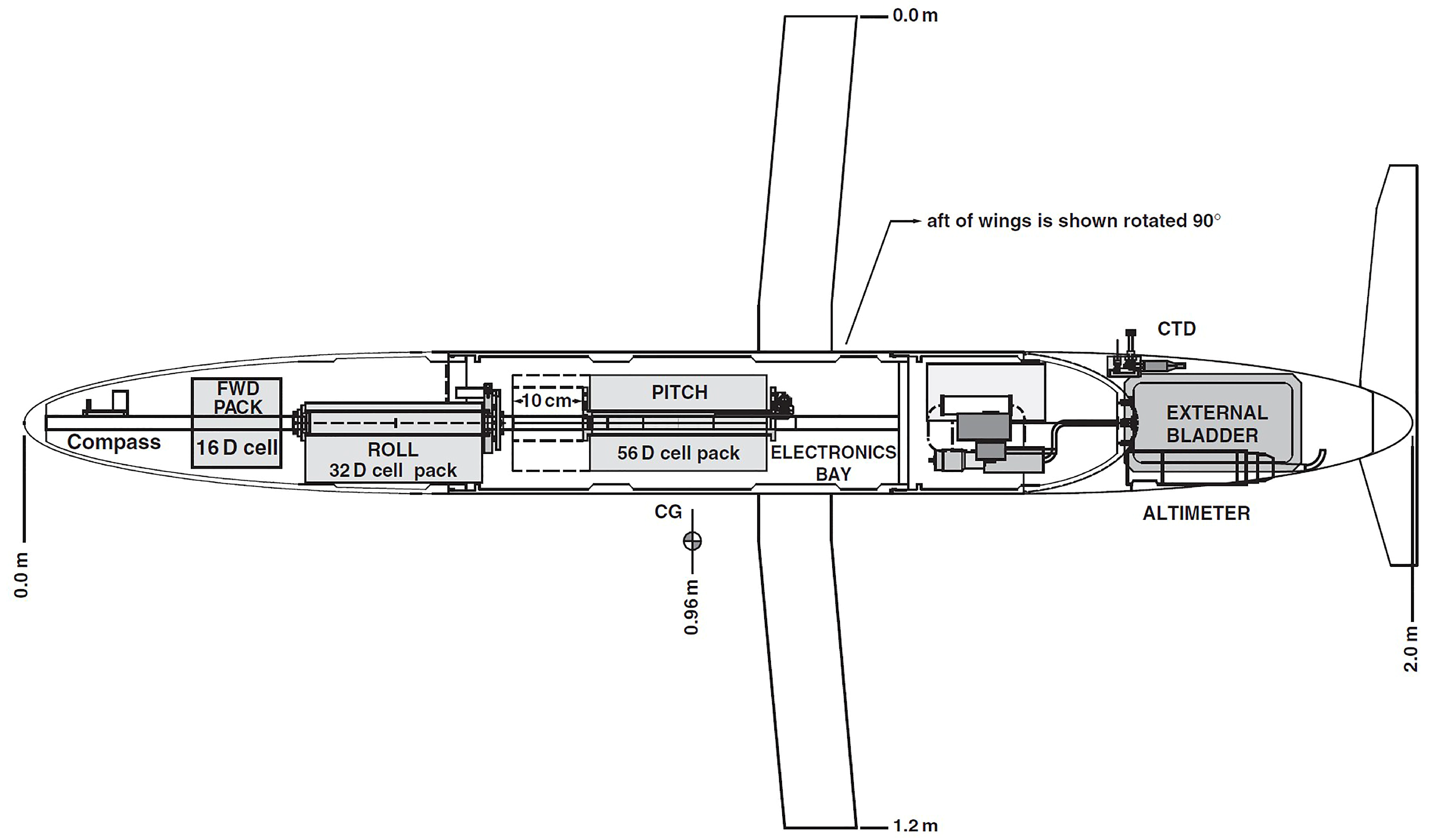
In 2016, the Slocum glider achieved a groundbreaking transoceanic mission, successfully crossing the North Atlantic Ocean in 330 days and covering a total distance of 6506.8 km [51], as illustrated in Figure 1. This mission marked the first application of Lagrangian Coherent Structures (LCS) theory for optimized path planning, significantly enhancing navigation accuracy and mission robustness under the constraints of low-resolution global ocean models. During the mission, the glider achieved a maximum cruising speed of 1.04 m/s and demonstrated substantial improvements in energy efficiency and system reliability. These results validated the practical utility of LCS-based path planning for long-range oceanographic missions, paving the way for advancements in long-endurance underwater glider operations.

3. Core Technologies of LRUGs

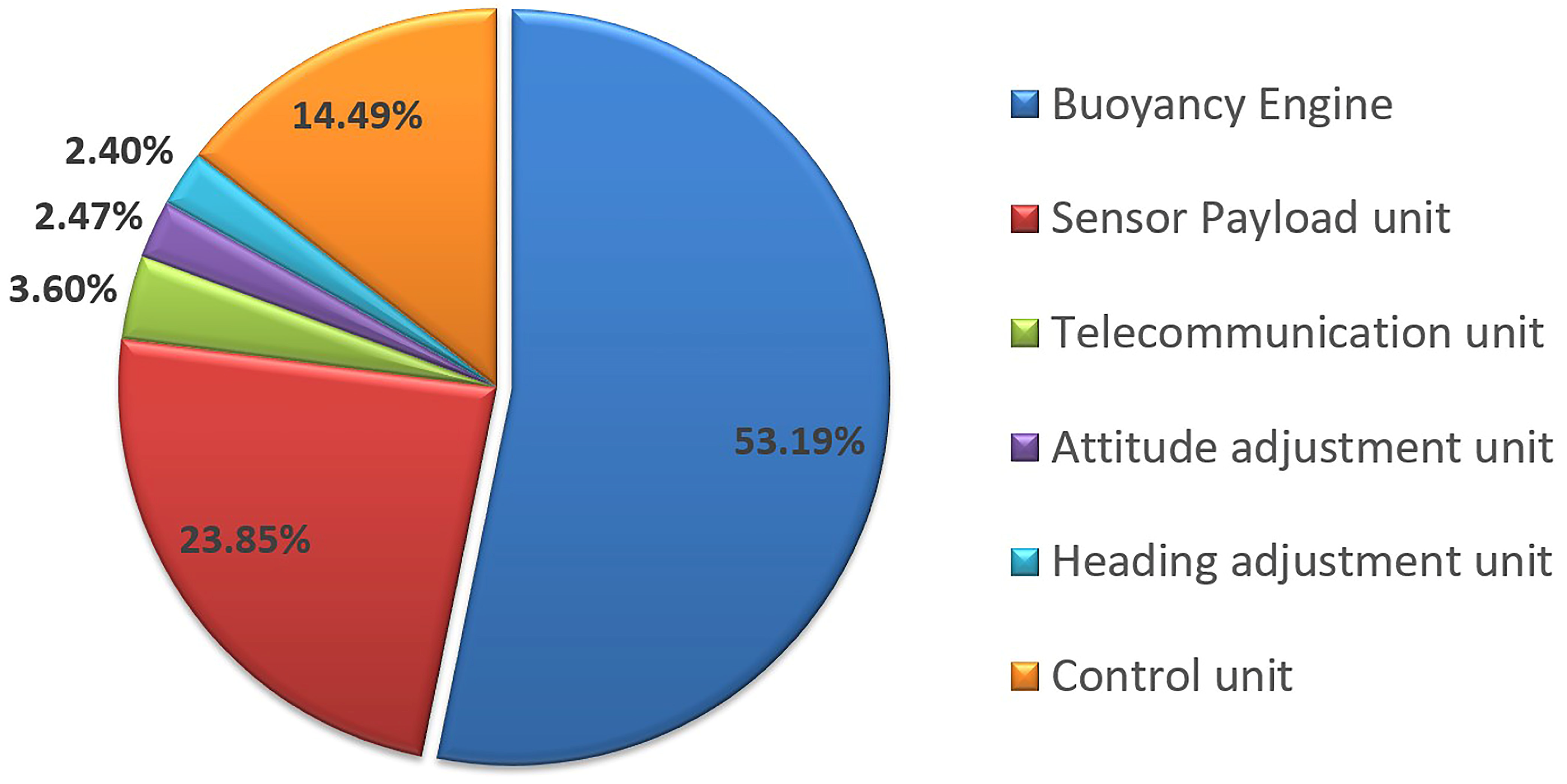
As a representative energy-constrained platform, the endurance performance of LRUGs is fundamentally governed by their onboard energy storage capacity and the overall system’s power efficiency. From a system architecture standpoint, multiple subsystems contribute to glider performance, including navigation technologies [52], path planning algorithms [53], control strategies [54], sensing technologies [55], communication systems [56], and hydrodynamic optimization [57]. Among these, two technologies stand out as the most critical: lightweight pressure-resistant hull structures and buoyancy-driven propulsion systems. The lightweight pressure-resistant hull reduces the structural mass through advanced material selection and optimized structural design, thereby increasing the energy capacity per unit mass [58]. This represents the most effective strategy for enhancing overall energy efficiency. Meanwhile, buoyancy-driven propulsion accounts for more than 50% of the system’s total energy consumption [59], underscoring the importance of improving its energy efficiency (Figure 2). Thus, substantial advancements in the glider’s range and operational endurance hinge upon breakthroughs in these two core technologies.

3.1. Lightweight and Pressure-Resistant Cabin Shell Technology

The pressure-resistant hull, as a critical load-bearing structure of underwater gliders, serves not only to maintain a stable operational environment for onboard power systems and electronic components under complex and dynamic oceanic pressures but also significantly influences the platform’s buoyancy control and payload efficiency through its structural mass and internal volume. As such, it plays a pivotal role in determining the glider’s endurance performance [60,61]. The design of the pressure hull thus necessitates a holistic approach that accounts for structural integrity, displacement-to-weight ratio, and manufacturability [62], with material selection constituting a central focus in the optimization process.

3.1.1. Material Lightweighting

Pressure-resistant hull materials for underwater gliders primarily consist of metals and non-metallic composites. Table 2 [63] compares the key performance parameters of 6061-T6 aluminum alloy, TC4 titanium alloy, and composite materials, including elastic modulus (E), shear modulus (G), Poisson’s ratio (ν), density (ρ), yield strength (σs), and axial compressive strength (Xc) for composites. The results demonstrate that composite materials possess significantly higher specific strength relative to conventional metals. Among composites, carbon fiber exhibits approximately 10% lower density and about 45% greater axial compressive strength compared to glass fiber.
Early underwater gliders primarily utilized aluminum alloys due to their well-established fabrication techniques, ease of machining, and relatively low production costs [64]. However, with the rapid development of high-performance composite manufacturing technologies derived from the aerospace industry [65,66], carbon fiber-reinforced composites—characterized by high specific strength, low density, and excellent corrosion resistance [67]—have gradually replaced metallic materials, becoming the predominant choice for pressure-resistant structures in underwater robotic systems [68].
In 2002, the University of Washington pioneered the application of IM7/8552 carbon fiber reinforced polymer (CFRP) composites in the fabrication of Deepglider pressure-resistant hulls. By utilizing aerospace-grade manufacturing techniques, the weight-to-displacement ratio was reduced to below 0.47 [58], significantly enhancing onboard energy capacity and sensor integration. Following the adoption of CFRP pressure housings, the Slocum glider achieved an approximate 15% increase in battery capacity, resulting in a marked improvement in endurance performance [69]. The “SeaWing-7000” underwater glider employed a T700 carbon fiber/epoxy resin system [70], and through structural topology optimization combined with multi-process weight reduction strategies, it attained a 40% reduction in structural mass while maintaining the required pressure resistance. This substantial weight reduction facilitated a significant increase in energy payload capacity.

3.1.2. Optimization of the Molding Process

The primary advantage of employing CFRP in pressure hull fabrication lies in the ability to tailor the manufacturing process to the hull’s geometric configuration and pressure-bearing requirements [71]. The ultimate performance of the pressure hull is not solely governed by the intrinsic mechanical properties of the carbon fiber material but also critically depends on the rationality of the fabrication process and the optimization of processing parameters [72]. At present, the main forming techniques utilized for CFRP pressure hulls in underwater gliders are filament winding (Figure 3) [73,74] and Automated Fiber Placement (AFP) [58].
Filament winding technology is widely employed in the fabrication of axisymmetric shells, offering superior control over fiber orientation and high laminate compaction quality. The process maintains consistent fiber tension via a tension control system and uniformly deposits carbon fibers onto a rotating mandrel following predefined guide paths. This method enables customized layup patterns and localized reinforcement, thereby effectively enhancing the overall mechanical performance of the structure [75,76]. This technique has been successfully applied in the fabrication of pressure-resistant housings for the “SeaWing” series underwater gliders.
AFP is particularly well-suited for fabricating deep-sea pressure hulls with complex geometric features. This technique utilizes multi-axis robotic arms to precisely steer pre-impregnated fiber tows, while compaction rollers apply consistent pressure, enabling high-precision, wrinkle-free layup even in regions of high curvature [77]. The incorporation of topology-optimized variable-angle layup paths and adaptive meshing strategies further enhances the laminate quality and mechanical performance [78,79]. Boeing has successfully employed AFP technology to manufacture the pressure hull of the Deepglider, achieving significant improvements in manufacturing consistency and structural reliability [58].
Overall, filament winding proves to be a highly efficient technique for manufacturing conventional axisymmetric pressure housings, whereas automated fiber placement (AFP) offers greater flexibility and precision for fabricating non-axisymmetric or geometrically complex structures. Nonetheless, several technical challenges—such as non-uniform curing, porosity control, and residual stress accumulation [80]—must be effectively addressed to further improve the structural performance and reliability of composite components.

3.1.3. Optimization of Compressibility and Seawater Density Matching

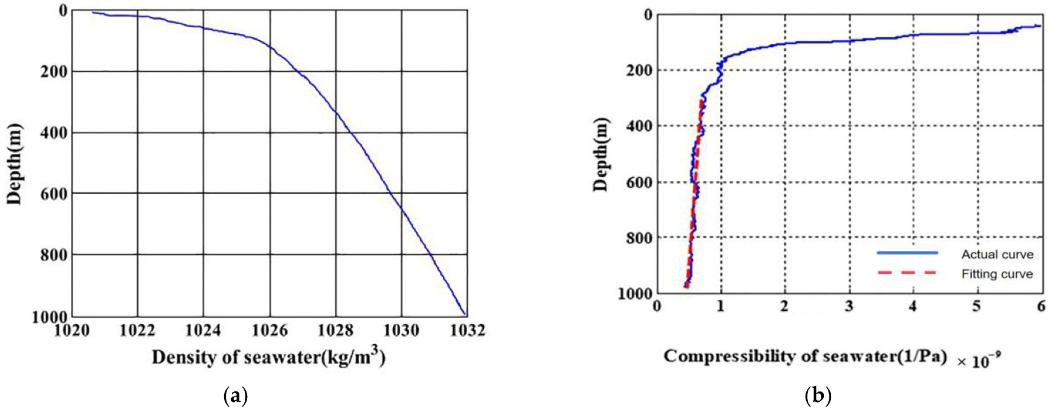
During deep-sea operations, the hydrodynamic efficiency of underwater gliders is significantly influenced by the coupled variations in hull compressibility and seawater density [81]. As depicted in Figure 4, seawater density exhibits a nonlinear dependence on temperature, salinity, and depth. Compressibility shows the most pronounced variation within the 0–300 m depth range, whereas from 300 m to 1000 m, it approaches a linear trend with an average value of approximately 0.59 × 10 9 Pa−1.
Aluminum alloy pressure housings exhibit significantly lower compressibility compared to seawater, necessitating frequent buoyancy adjustments to accommodate depth variations, which in turn increases energy consumption [82]. In contrast, carbon fiber-reinforced composites offer superior compressibility-matching characteristics [83]. For example, Merckelbach et al. [69] experimentally determined the compressibility of approximately 6.4 × 10⁻¹⁰ Pa−1 for the Slocum glider pressure hull by optimizing fiber orientation and resin matrix, a value closely aligned with that of seawater (Figure 5). Similarly, Osseet et al. [58] reduced strain gradients and residual stresses through ply sequence optimization and the implementation of shear control strategies. Laboratory tests demonstrated that pressure housings fabricated from the thermoplastic composite AS4/PEEK exhibited compressibility comparable to seawater under 60 MPa pressure [84], thereby ensuring structural stability in deep-sea high-pressure environments while minimizing the extent of buoyancy adjustments required.
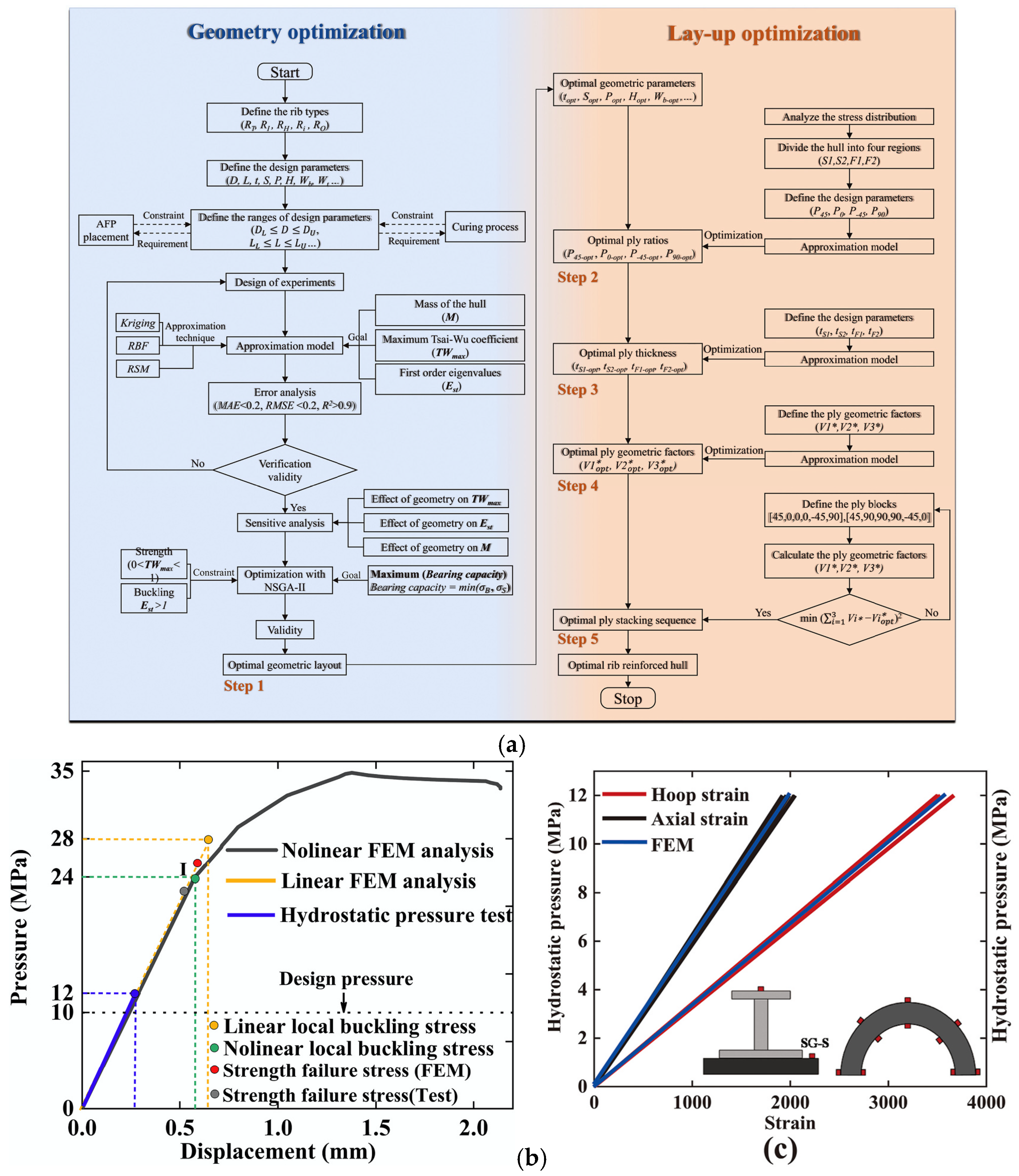
Gao et al. [85] proposed a collaborative hierarchical optimization design methodology tailored for composite pressure hulls, which integrates the systematic optimization of both geometric configuration and laminate architecture (Figure 6a). In the geometric optimization phase, surrogate modeling techniques are applied to conduct parametric sensitivity analyses across various representative stiffening configurations, enabling a comprehensive evaluation of their impacts on hull weight, structural stability, and strength under different length-to-diameter ratios. This facilitates a comparative assessment of reinforcement efficiency among different designs. Subsequently, the complex laminate optimization task is decomposed into several submodules, including load-bearing capacity analysis, ply proportion optimization, thickness optimization, and ply sequence optimization. This hierarchical strategy significantly improves structural performance and achieves a buoyancy factor reduction of up to 33%. The final optimized design is validated through finite element simulations and hydrostatic pressure tests, which show strong agreement (Figure 6b,c), thereby confirming the effectiveness and feasibility of the proposed methodology for deep-sea composite pressure hull design. Furthermore, this methodology exhibits strong scalability. By integrating seawater density models and relevant parameters, it can be extended to support the joint optimization of hull compressibility and seawater density matching, offering a promising technical pathway for the development of deep-sea platforms with enhanced environmental adaptability.

3.1.4. Anti-Biological Attachment of the Pressure-Resistant Cabin Shell

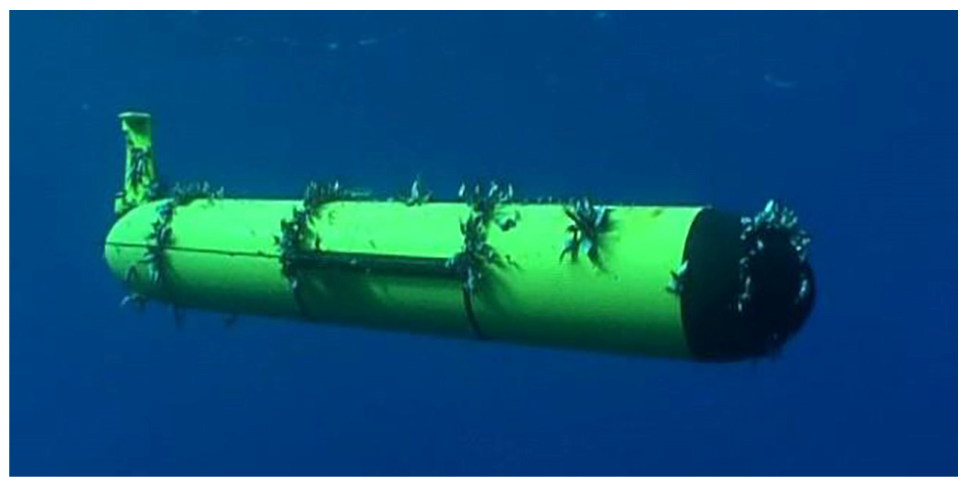
Due to their low-speed, long-duration operation in complex marine environments, underwater gliders are particularly prone to biofouling on the surfaces of their pressure-resistant hulls. This biofouling can significantly impair platform performance and compromise the accuracy of scientific observations. For example, during a trans-Atlantic deployment, the Slocum glider experienced severe biofouling by marine organisms such as barnacles after four months of continuous operation, which significantly disrupted its trajectory control. As a result, the vertical gliding speed decreased to just 10% of its original value, ultimately leading to mission failure [86] (Figure 7). Similarly, during operations near the Galápagos Islands, the Spray glider suffered substantial biofouling on its bow section, which not only increased hydrodynamic drag but also adversely affected the accuracy of vertical velocity measurements [87].
Biofouling exerts a broad spectrum of adverse effects on the operational performance of underwater gliders, primarily affecting material integrity, hydrodynamic efficiency, and sensor functionality. First, the colonization of marine organisms can degrade the protective anti-corrosion coatings on the glider’s exterior, initiating localized pitting and electrochemical corrosion of metallic components. This substantially increases the risk of material failure, thereby reducing fatigue life and shortening the overall service lifespan of the vehicle [88]. Second, biofouling elevates surface roughness and frictional drag, leading to deteriorated hydrodynamic performance. Consequently, gliding efficiency decreases while energy consumption per unit distance rises, severely constraining the glider’s operational range and endurance [89]. Moreover, biofouling accumulation on critical sensor interfaces, such as temperature-salinity probes or dissolved oxygen membrane heads, can introduce measurement noise, increase response latency, or cause sensor malfunction. These impairments may activate onboard protection protocols that prematurely terminate missions, thus compromising the integrity and continuity of oceanographic data collection [90].
To mitigate the risk of biofouling, recent years have seen significant progress in antifouling material systems, marked by a transition from traditional toxic coatings to environmentally friendly and intelligent antifouling strategies. Currently, the predominant approach involves the use of non-toxic, polymer-based antifouling coatings that exploit low surface energy and low elastic modulus to weaken the adhesion strength of marine organisms, thereby promoting their removal under hydrodynamic shear forces [91]. In addition, biomimetic superhydrophobic coatings have garnered increasing attention due to their “lotus effect.” These coatings combine micro- and nano-scale surface textures with low-surface-energy chemical compositions to form stable air cushion barriers, effectively preventing the initial adhesion of fouling organisms. For instance, Xie et al. [92] developed a ZnO/polyurethane acrylate composite coating, which significantly inhibited diatom attachment during a 150-day seawater immersion test, demonstrating strong potential for long-term marine applications.
In summary, carbon fiber-reinforced composite pressure hull technology, distinguished by its outstanding specific strength and favorable compressibility-matching characteristics, offers significant technical advantages in enhancing energy capacity and reducing power consumption. These features provide essential structural support and ensure the operational reliability of LRUGs. The evolution from rigid structural platforms to environmentally adaptive systems has become a key paradigm shift in the design of autonomous, long-duration deep-sea observation platforms.

3.2. High-Efficiency Buoyancy Drive Technology

To fulfill the demands of long-range, low-power ocean observation missions, underwater gliders typically utilize buoyancy-driven propulsion systems as energy-efficient alternatives to conventional thrusters [21]. Since its inception in the 1980s, buoyancy control technology has undergone significant advancements, evolving from basic hydraulic actuation mechanisms to intelligent, multi-modal integrated systems. These technological developments have led to a variety of implementation strategies and have firmly established buoyancy regulation as a key enabling technology for achieving extended-endurance glider operations.

3.2.1. Active–Passive Coupled Buoyancy Adjustment Mechanism
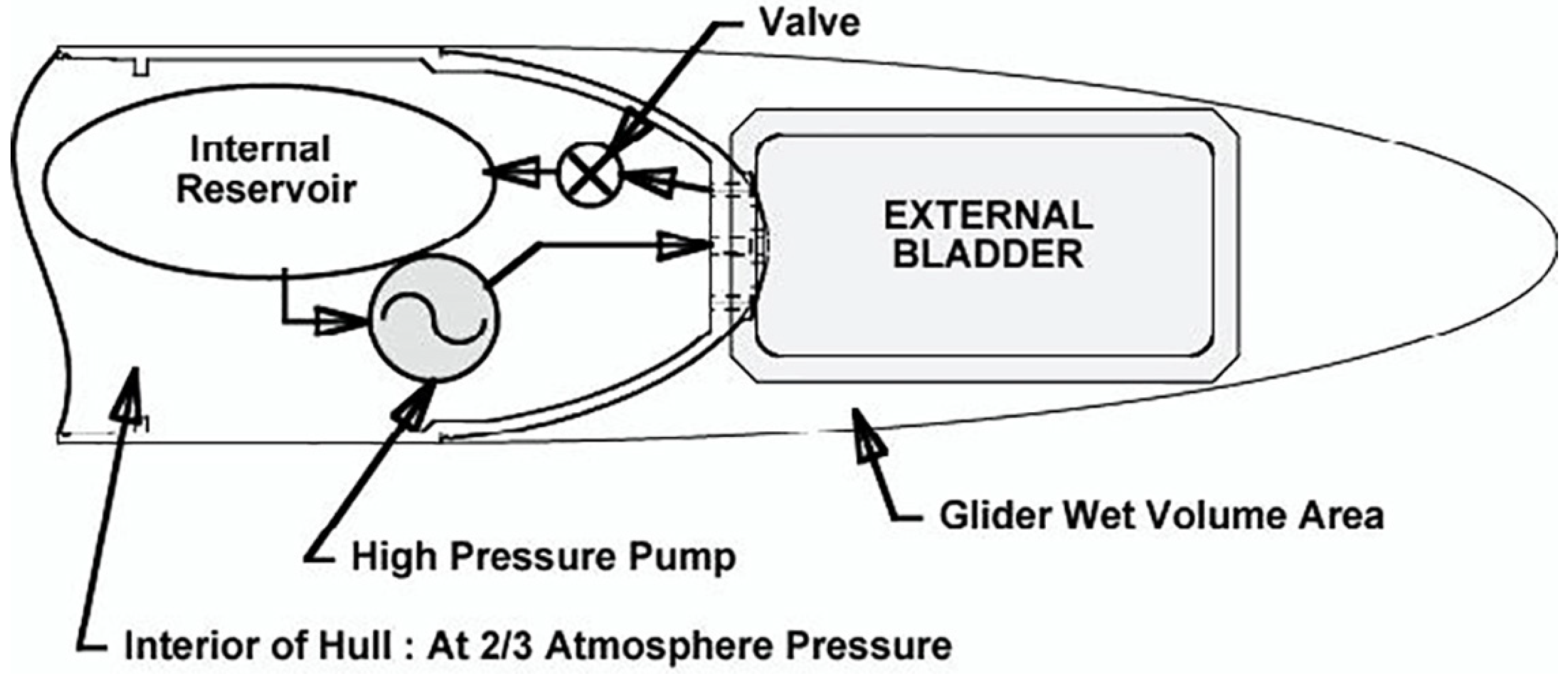
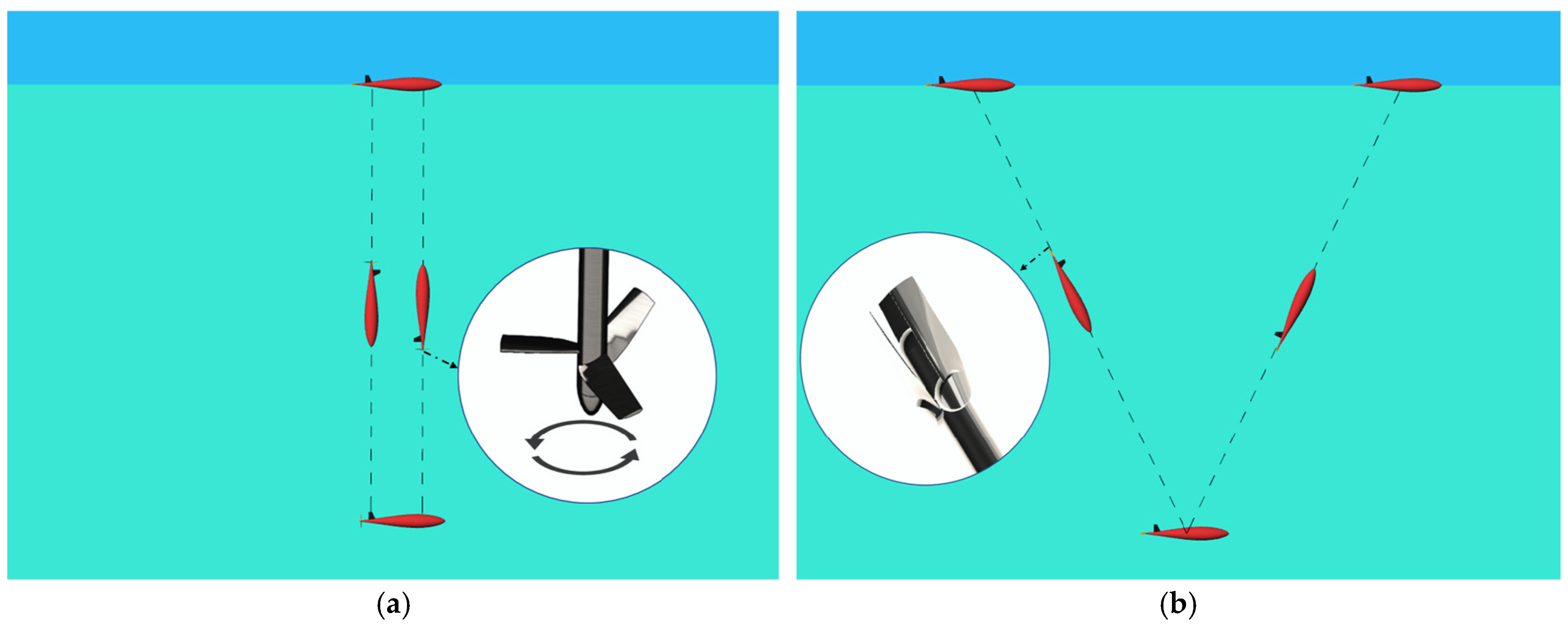
At present, active buoyancy control in underwater robotic systems primarily relies on two approaches: variable ballast systems and variable volume mechanisms [93]. Among these, hydraulic variable volume systems based on oil bags represent the most mature and widely adopted solution (Figure 8) and have become the mainstream configuration for LRUGs [21].
The early application of buoyancy control systems can be traced back to the development of the ALACE float by Davis et al. [94], which utilized a combined configuration of an axial piston pump and a vacuum oil reservoir. While this design enabled basic buoyancy regulation, it was prone to cavitation under deep-sea conditions due to microbubble formation at the oil intake, resulting in reduced hydraulic efficiency. To enhance system performance, the buoyancy control system of the Spray glider (Figure 9) integrates a high-compression-ratio axial piston pump, achieving a 900 cc buoyancy adjustment capacity with 50% energy conversion efficiency at 1000-m depths [95]. To address early system failures and ensure adequate supply pressure for the high-pressure pump, Seaglider (Figure 10) incorporated a separate boost pump, thereby enhancing overall reliability and operational stability. The system’s efficiency was further improved through the integration of balanced check valves, which increased the pumping rate by approximately 50% under near-atmospheric pressure without additional power consumption [28].
Figure 8. Buoyancy control mechanism on a glider. Reproduced with permission from [96].
Jmse 13 01509 g008
Figure 9. Schematic diagram of Spray and buoyancy adjustment system. Reproduced with permission from [97].
Jmse 13 01509 g009
Figure 10. Schematic diagram of Seaglider and buoyancy adjustment system. Reproduced with permission from [28].
Jmse 13 01509 g010
Although active hydraulic systems offer robust buoyancy control capabilities, their continuous operation requires frequent activation of high-power pumps, resulting in substantial energy consumption—an unfavorable characteristic for ultra-long-endurance missions. As a result, passive buoyancy regulation mechanisms have attracted growing interest due to their inherently low energy requirements. In addition to neutral buoyancy pressure hull technologies (see Section 3.1.3), current passive compensation strategies primarily include the following three types of devices:
(1)
Spring-supported piston–cylinder structures: Rossby et al. [98] developed a device of this type to enable adaptive density regulation, which closely aligns with the compressibility characteristics of seawater, thereby enhancing vertical profile control accuracy;
(2)
Gas-charged accumulator-type compensators: Chen et al. [99] utilized an accumulator-based design to mitigate buoyancy fluctuations in underwater gliders. Simulation results indicate strong potential for addressing buoyancy instability in such systems;
(3)
Compressible fluid compensators: Wang et al. [100] proposed a compensator employing low-viscosity silicone oil as the working fluid, achieving a measured 70.8% reduction in net buoyancy variation.
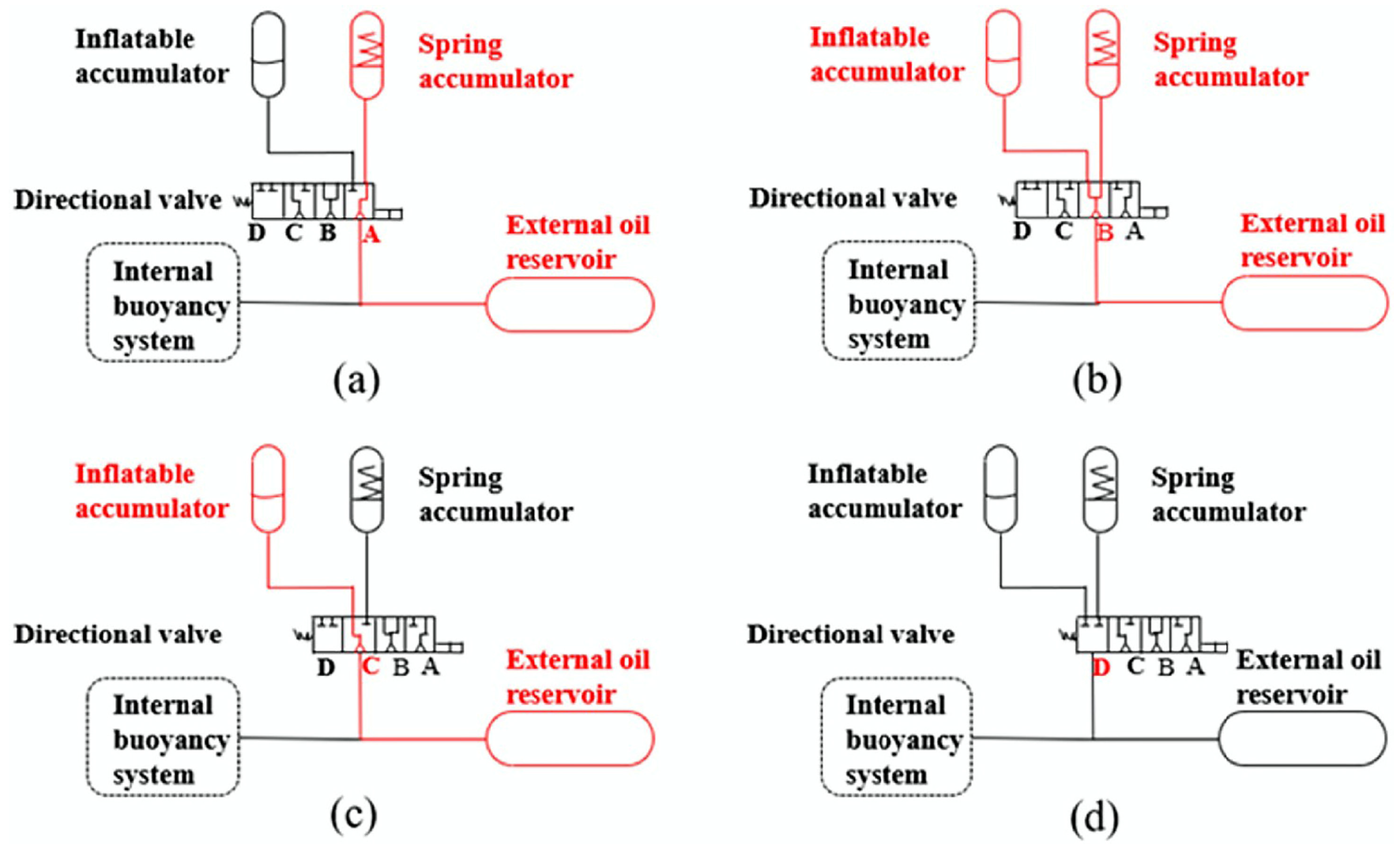
Building upon these developments, Xie et al. [101] proposed a hybrid passive buoyancy compensation system integrating a spring accumulator, a gas-charged accumulator, and a silicone oil bladder. Utilizing a directional valve, the system enables dynamic switching among multiple mechanisms (Figure 11), allowing adaptive selection of the optimal compensation strategy according to varying depths. This innovation offers critical technical support for “full ocean depth” glider missions. Looking ahead, composite regulation mechanisms that combine active fine-tuning with passive dominant control are anticipated to significantly improve system energy efficiency while maintaining control precision and responsiveness.

3.2.2. High-Response Execution Mechanism Based on Smart Materials

Smart materials, which respond mechanically to solid-state phase transformations, offer innovative and efficient solutions for buoyancy regulation in underwater gliders. Among them, shape memory alloys (SMAs) stand out as promising candidates for solid-state actuators due to their superior superelasticity and high recoverable strain—up to 8% in practice. These characteristics enable compact, silent, and repeatable actuation with minimal mechanical complexity. In buoyancy control systems, SMA actuators can deform internal structures or displace working fluids, effectively replacing conventional miniature pumps or motor-driven pistons in specific configurations. This substitution not only reduces mechanical complexity but also improves system reliability and compactness, making SMA-based actuators particularly well-suited for long-duration, low-maintenance underwater missions [102,103].
(1)
Environmentally Driven Temperature-Differential Passive System
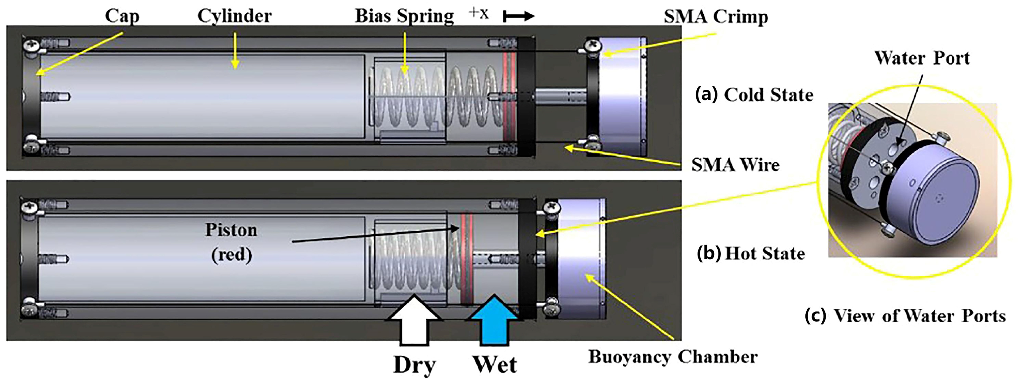
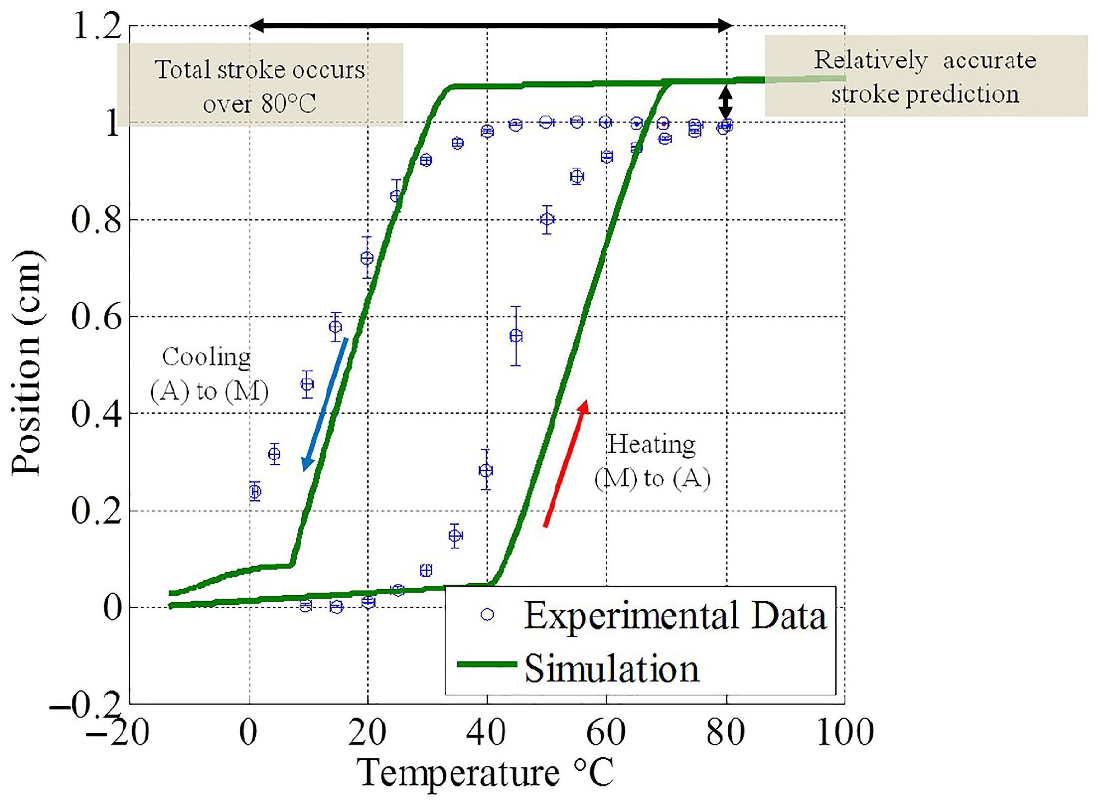
Angilella et al. [95] proposed a shape memory alloy buoyancy heat engine (SMA-BHE; Figure 12), which utilizes thermocline-induced temperature differentials (ΔT ≥ 15 °C) to trigger austenite–martensite phase transformations, thereby modulating displacement volume through axial strain. Experimental results demonstrated a total stroke of 1.0 cm, with a relative error of only 7.4% compared to the 1.08 cm predicted by Brinson’s constitutive model, thereby validating the feasibility and stability of passive temperature-differential actuation in marine environments (Figure 13).
(2)
An Active Actuation Mechanism Based on Electrothermal Excitation
To overcome the limitations imposed by oceanic thermal gradients, Yang et al. [104] developed an active SMAs buoyancy actuator that utilizes electrical current to induce phase transformations, thereby enabling precise volumetric modulation across a wide range of environmental conditions. The experimental results demonstrated a minimum adjustable volume of 1.5 mL and approximately a 40% improvement in control accuracy. However, the system’s high current demand—up to 8.4 A at 1 MPa—presents challenges for long-duration deep-sea missions. Compared to micro-pumps (1 A), active SMA actuators consume significantly more power. Their current requirement also increases rapidly with pressure and may exceed onboard power limits in ultra-deep environments (10 MPa), leading to thermal and energy constraints that affect system reliability and endurance. These challenges underscore the need for energy-efficient designs and careful assessment of active SMA actuator suitability for high-pressure underwater applications (Table 3).

3.2.3. Ocean Thermal Gradient Energy Drive and Energy Recovery Mechanism

Ocean thermal gradient energy harvesting enables buoyancy modulation via the solid–liquid phase transitions of phase change material (PCM), offering significantly higher energy density and enhanced environmental adaptability compared to the solid-state phase transformation mechanisms utilized in shape memory alloys (SMAs). The technological development in this field can be broadly categorized into three evolutionary stages, as follows:
(1)
Proof-of-concept stage (2001–2010)
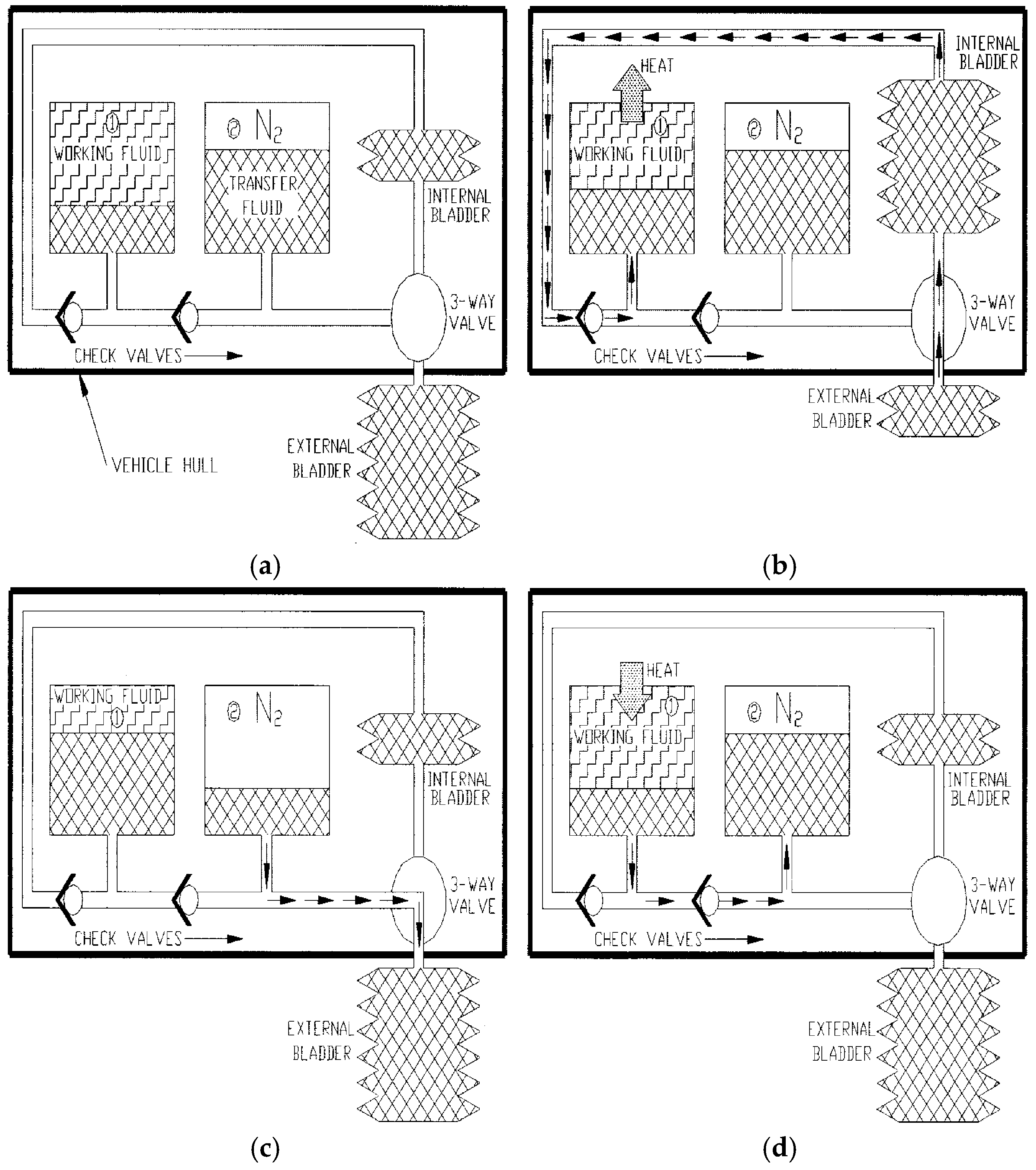
Webb et al. [105] pioneered the implementation of a temperature-differential-driven thermal engine in the “Slocum Thermal” glider. As shown in Figure 14, the system harnesses the temperature gradient between warm surface waters and cold deep-sea layers to drive a hydraulic actuation mechanism. This mechanism converts the volumetric expansion of a PCM, triggered by its phase transition, into controllable buoyancy changes. Although the thermal efficiency was relatively low—approximately 3%—this effort successfully demonstrated the feasibility of converting ocean thermal gradients into usable mechanical energy for underwater gliders, thus completing foundational at-sea trials.
(2)
Thermal Cycle Optimization Stage (2010–2020)
Teledyne Webb Research developed the “Slocum Thermal E-Twin” system [106], which incorporates a dual heat exchanger configuration that significantly enhances the system’s buoyancy modulation capability, achieving volume changes exceeding 1000 mL. The design integrates rechargeable secondary batteries, enabling bidirectional energy conversion between hydraulic and electrical systems, as depicted in Figure 15. This platform successfully completed a 45-day sea trial, performing 72 thermally driven profiling cycles at depths reaching 1150 m. These results demonstrated the system’s high engineering reliability and strong applicability for long-duration operations in real-world oceanic environments.
(3)
Energy Recovery Integration Phase (2020–Present)
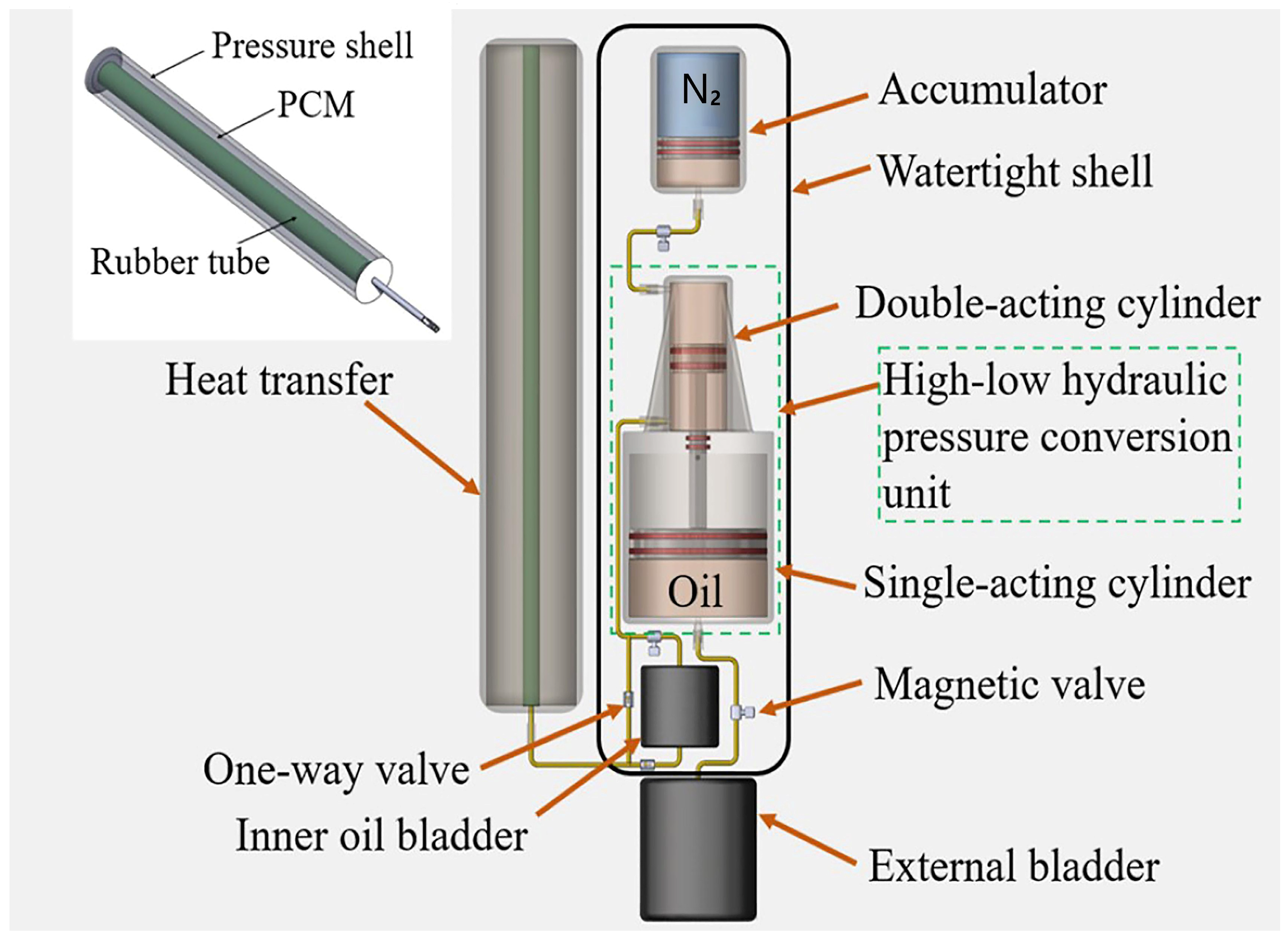
Hou et al. [107] proposed an advanced temperature-differential-driven system that integrates several critical innovations—including high-pressure amplified phase change, mechanical gain amplification, and turbine-based energy recovery—to significantly enhance energy conversion efficiency and actuation performance. First, during the phase change actuation process, the nitrogen precharge pressure was elevated to 85 MPa, enabling high-pressure amplified phase transformation by substantially increasing the expansion ratio of the PCM. Second, a piston-lever mechanism was implemented to achieve mechanical gain amplification, magnifying the PCM’s intrinsic volume change by a factor of 2.5, thereby enhancing overall volumetric displacement (Figure 16). Finally, for energy recovery, a micro-turbine structure was designed to operate in energy harvesting mode (Figure 17a), recovering up to 24.2 kJ of electrical energy per cycle—sufficient to power approximately four subsequent gliding propulsion events (Figure 17b). These technological advancements significantly improve both the energy efficiency and engineering viability of temperature-gradient-driven buoyancy actuation systems [108].
Buoyancy-driven systems in underwater gliders can be categorized based on their reliance on environmental conditions and the controllability of buoyancy adjustment. Specifically, active hydraulic drives operate independently of environmental changes and enable precise, real-time control of buoyancy through continuous energy input. In contrast, passive compensation mechanisms rely entirely on environmental pressure changes and provide non-controllable, delayed responses without real-time actuation. Between these two extremes lie the SMA drive and thermal energy drive, which also depend on environmental stimuli (such as pressure or temperature gradients) but allow programmed or controllable buoyancy modulation through material design or external activation. These mechanisms offer a compromise between energy efficiency and controllability. A detailed comparison of these buoyancy-driven regulation technologies is presented in Table 4.

4. Discussion and Future Development

4.1. Challenges

Although LRUGs have achieved operational ranges approaching 10,000 km and demonstrated outstanding capabilities in transoceanic basin profiling and polar under-ice monitoring missions, their single-mission duration remains significantly shorter than that of Argo floats, which can operate continuously for up to five years [109]. This disparity results in substantially higher operational and maintenance costs, thereby constraining the feasibility of large-scale, substitute deployments. In addition, accurate georeferencing of data acquisition points is essential to ensure the spatial validity of observations in global-scale monitoring networks [110]. The key challenges in achieving extended endurance can be broadly classified into four categories: structural lightweighting, surface antifouling, buoyancy system energy efficiency, and thermal energy harvesting.
(1)
Trade-off Between Lightweighting and Reliability of Pressure-Resistant Housings
Carbon fiber-reinforced composites have been widely adopted for glider pressure housings due to their excellent specific strength. However, further improvements in energy payload capacity and reductions in overall system mass require either increasing the fiber volume fraction or employing thin-walled filament-wound structures—approaches that may compromise structural reliability under high-pressure operational conditions. In real-world applications, critical defects such as local buckling, interlaminar delamination, and resin voids—often induced during the filament winding process—pose significant constraints on long-term operation in deep-sea environments. Therefore, it is imperative to optimize the coupled design of density, mechanical strength, and reliability while maintaining sufficient structural safety margins.
(2)
Biofouling Risks to Pressure-Resistant Structures During Long-Term Deployment
During prolonged ocean deployments, the external surfaces of underwater gliders are highly susceptible to biofouling by marine organisms such as algae and shellfish. This biological accumulation leads to a substantial increase in hydrodynamic drag, degrades attitude control accuracy, and compromises the performance of onboard sensors. Although the current Slocum glider employs transparent antifouling coatings, such as ClearSignal™, which offer partial resistance to biological adhesion, their long-term effectiveness is limited—particularly under complex and fluctuating temperature–salinity conditions [111]. Furthermore, antifouling strategies based on a single mechanism have proven inadequate in addressing the diverse and dynamic nature of biofouling across varying spatial and temporal scales, thus falling short of meeting the glider’s requirements for extended, cross-latitudinal, and multi-seasonal operations.
(3)
Energy Efficiency Bottlenecks in Buoyancy Regulation Systems
Modern underwater gliders predominantly utilize oil bladder–based hydraulic actuators for buoyancy regulation. While these systems offer high controllability and fast response times, they are associated with considerable energy consumption—particularly during deep-sea operations involving high-frequency, rapid profiling maneuvers. This imposes a significant power burden on active buoyancy control systems. In contrast, passive buoyancy regulation approaches demonstrate promising potential for energy savings. However, they remain limited by low control accuracy and insufficient dynamic responsiveness, with most designs still confined to the proof-of-concept stage. Achieving an optimal trade-off between precise control and energy efficiency, along with the development of engineering-ready hybrid active–passive buoyancy systems, remains a critical challenge in the design and deployment of next-generation underwater gliders.
(4)
Limitations in Efficiency and System Integration of Thermal Gradient–Driven Buoyancy Regulation
Ocean thermal energy offers compelling advantages due to its broad spatial availability and long-term sustainability, presenting a theoretical pathway toward “unlimited endurance” for underwater glider operations. However, current thermally driven buoyancy systems suffer from low energy conversion efficiency, intricate mechanical configurations, and slow actuation responses, which limit their applicability in missions requiring rapid vertical profiling. Although recent innovations such as turbine-based energy recovery and high-pressure phase transition enhancements have improved performance metrics, several core challenges persist. Among these are the intrinsically low thermal conductivity of phase change materials and inadequate system-level mechanical integration. These limitations continue to hinder the transition from controlled laboratory experiments to robust, field-operational engineering solutions capable of long-term deployment in complex ocean environments.

4.2. Future Development

To address the demands of extended-duration missions and global-scale deployment of underwater glider networks, the next generation of long-range underwater gliders (LRUGs) should be built upon a fully integrated system architecture that ensures prolonged operational endurance, enhanced adaptability to dynamic oceanic environments, and long-term energy self-sufficiency. In response to the aforementioned challenges, future research and development should focus on achieving breakthroughs in the following four fundamental areas.
(1)
Material Innovations for Ultralight, High-Strength Pressure-Resistant Structures
To transcend the performance constraints of traditional carbon fiber composites, the development of next-generation pressure hulls for underwater gliders necessitates the adoption of advanced structural material systems that combine low density, high mechanical strength, and exceptional fatigue resistance. Ultra-high molecular weight polyethylene (UHMWPE), characterized by its low density (0.97 g/cm3), compressive strength exceeding 800 MPa, superior corrosion resistance, electromagnetic transparency, and excellent fatigue performance, has already shown considerable promise in aerospace, defense, and marine applications [112]. If current manufacturing limitations, such as challenges in thermoplastic processing and dimensional instability [113], can be effectively resolved, UHMWPE-based composites could emerge as a compelling candidate for constructing pressure hulls with high specific energy, enhanced structural integrity, and extended operational longevity.
(2)
Multi-Mechanism Coupled Antifouling Technology System
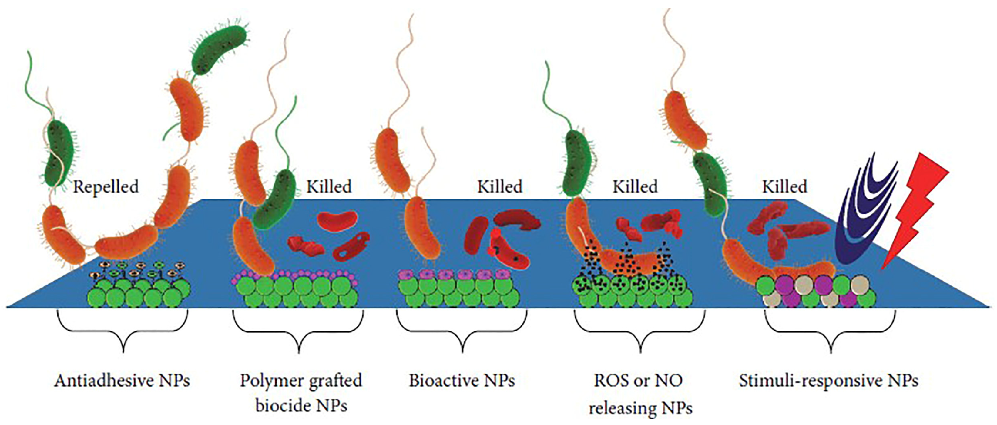
For underwater gliders operating in long-term marine environments, an effective antifouling system must integrate multiple mechanisms, including physical barriers, chemical inhibition, and biological regulation. Superhydrophobic surfaces can significantly lower surface energy, sustain stable air layers, and inhibit the initial stages of biofouling. Nanoparticle-based controlled-release systems offer prolonged antifouling performance by establishing localized chemical gradients in the surrounding microenvironment [114] (Figure 18). Moreover, enzyme-mediated regulatory approaches can interfere with microbial metabolic processes at the molecular level, thereby impeding the formation of early-stage fouling communities [115]. These combined antifouling strategies exhibit high adaptability across spatial and temporal scales, effectively reducing maintenance frequency and improving the environmental resilience of underwater gliders in cross-seasonal and multi-latitude operational scenarios.
(3)
Efficient Hybrid Active–Passive Buoyancy Regulation Systems
To reduce energy consumption while ensuring reliable performance, the design of hybrid active–passive buoyancy regulation systems has become a central research direction in underwater glider development. Passive regulation strategies typically exploit the compressibility of pressure-resistant hulls and fluid/gas compensation structures, offering advantages such as mechanical simplicity, stable operational response, and negligible power usage, making them particularly suitable for baseline buoyancy control under fluctuating hydrostatic pressures. In contrast, active systems incorporating compact hydraulic actuators or smart materials allow for high-precision, real-time buoyancy adjustment. Future innovation should emphasize the integration of environmental perception capabilities with adaptive control algorithms, enabling intelligent hybrid architectures that dynamically switch between regulation modes according to mission demands and surrounding conditions. Such advancements promise to significantly lower energy consumption, enhance endurance, and improve attitude control accuracy while maintaining robust performance across complex marine environments.
(4)
High-Efficiency, Self-Sustaining Gliding Platform Powered by Environmental Thermal Energy
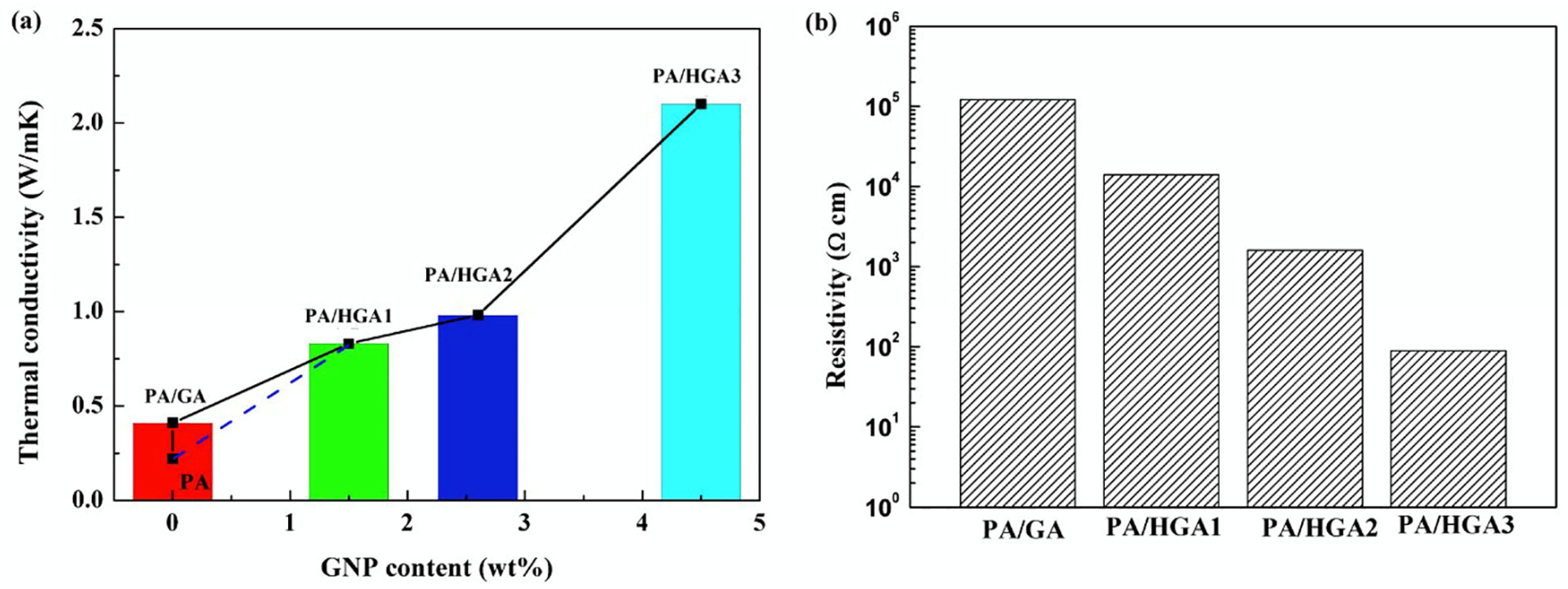
The next generation of thermally driven underwater gliders should be designed around a closed-loop energy architecture that integrates the high-pressure phase transition, thermal energy harvesting, and intelligent control. In this framework, graphene aerogels, with their highly interconnected three-dimensional thermal conduction networks and porous structures, can enhance radial thermal conductivity by up to 379% [116], significantly improving heat transfer efficiency under naturally occurring thermal gradients. Additionally, hybrid graphene aerogels maintain latent heat capacities as high as 206 J/g, while their nanoscale confinement effects optimize crystal phase migration, enabling simultaneous improvements in both thermal conductivity and latent heat utilization efficiency [117] (Figure 19). When coupled with high-efficiency microturbine-based energy recovery units capable of converting mechanical energy into electrical power, the platform can continuously support low-power operations such as attitude adjustment and communication. This system architecture holds strong potential to enable multi-year autonomous glider missions without external recharging, thereby laying the foundation for low-maintenance, globally distributed ocean observation networks.

5. Conclusions

Amid growing global demands for sustained deep and ultra-deep ocean observations, LRUGs have emerged as strategic platforms for advancing ocean science toward a multi-scale, integrated understanding of marine processes. Their strengths in high-resolution sensing, expansive spatial coverage, and low energy consumption render them highly suitable for long-duration, networked deployments. This paper provides a comprehensive review of recent advances in research and engineering, with a particular focus on two core technological areas: lightweight pressure-resistant structures and high-efficiency buoyancy regulation systems. Carbon fiber composites offer clear advantages in specific strength, compressibility compatibility, and mass reduction through process optimization; however, improvements in long-term reliability and environmental resilience remain necessary. Buoyancy regulation is transitioning from purely active systems to hybrid active–passive architectures, where smart material actuators and thermally driven energy harvesting strategies have shown considerable promise. Despite ongoing challenges related to structural weight reduction, antifouling robustness, and autonomous energy management, future innovations in advanced materials, adaptive control schemes, and the efficient harnessing of environmental energy are expected to accelerate the development of next-generation gliders. These platforms will feature ultra-long endurance, enhanced adaptability to complex ocean environments, and intelligent self-sustaining capabilities, forming essential infrastructure for global ocean observation networks and multiscale coupled oceanographic research.

Author Contributions

X.W.: Conceptualization, Validation, Writing—original draft. C.W.: Investigation, Writing—review and editing. K.Z.: Methodology, Supervision, Conceptualization. K.R.: Validation, Formal analysis, Investigation. J.Y.: Funding acquisition, Project administration, Supervision. All authors have read and agreed to the published version of the manuscript.

Funding

This work was supported by the National Key R&D Program of China (Grant No. 2021YFC2803101).

Institutional Review Board Statement

Not applicable.

Informed Consent Statement

Not applicable.

Data Availability Statement

No data were used for the research described in the article.

Conflicts of Interest

The authors declare no conflicts of interest.

References

  1. Wunsch, C. Vertical Mixing, Energy, and the General Circulation of the Oceans. Annu. Rev. Fluid Mech. 2004, 36, 281–314. [Google Scholar] [CrossRef]
  2. Chelton, D.B.; Gaube, P.; Schlax, M.G.; Early, J.J.; Samelson, R.M. The Influence of Nonlinear Mesoscale Eddies on Near-Surface Oceanic Chlorophyll. Science 2011, 334, 328–332. [Google Scholar] [CrossRef] [PubMed]
  3. Mahadevan, A. The Impact of Submesoscale Physics on Primary Productivity of Plankton. Ann. Rev. Mar. Sci. 2016, 8, 161–184. [Google Scholar] [CrossRef]
  4. Moum, J.N.; Klymak, J.M.; Nash, J.D.; Perlin, A.; Smyth, W.D. Energy Transport by Nonlinear Internal Waves. J. Phys. Oceanogr. 2007, 37, 1968–1988. [Google Scholar] [CrossRef]
  5. Xuan, J.; Ding, R.; Ni, X.; Huang, D.; Chen, J.; Zhou, F. Wintertime Submesoscale Offshore Events Overcoming Wind-Driven Onshore Currents in the East China Sea. Geophys. Res. Lett. 2021, 48, e2021GL095139. [Google Scholar] [CrossRef]
  6. Le Quere, C.; Rodenbeck, C.; Buitenhuis, E.T.; Conway, T.J.; Langenfelds, R.; Gomez, A.; Labuschagne, C.; Ramonet, M.; Nakazawa, T.; Metzl, N.; et al. Saturation of the southern ocean CO2 sink due to recent climate change. Science 2007, 316, 1735–1738. [Google Scholar] [CrossRef]
  7. Rahmstorf, S. Ocean circulation and climate during the past 120,000 years. Nature 2002, 419, 207–214. [Google Scholar] [CrossRef]
  8. Cheng, L.; Trenberth, K.E.; Fasullo, J.; Boyer, T.; Abraham, J.; Zhu, J. Improved estimates of ocean heat content from 1960 to 2015. Sci. Adv. 2017, 3, e1601545. [Google Scholar] [CrossRef]
  9. Bryden, H.L.; Longworth, H.R.; Cunningham, S.A. Slowing of the Atlantic meridional overturning circulation at 25 degrees N. Nature 2005, 438, 655–657. [Google Scholar] [CrossRef]
  10. Vellinga, M.; Wood, R.A. Global Climatic Impacts of a Collapse of the Atlantic Thermohaline Circulation. Clim. Change 2002, 54, 251–267. [Google Scholar] [CrossRef]
  11. Trenberth, K.E.; Fasullo, J.T. Atlantic meridional heat transports computed from balancing Earth’s energy locally. Geophys. Res. Lett. 2017, 44, 1919–1927. [Google Scholar] [CrossRef]
  12. McWilliams, J.C. Submesoscale currents in the ocean. Proc. Math. Phys. Eng. Sci. 2016, 472, 20160117. [Google Scholar] [CrossRef] [PubMed]
  13. Momeni, K.; Ma, Y.; Peltier, W.R.; Menemenlis, D.; Thakur, R.; Pan, Y.; Arbic, B.K.; Skitka, J.; Alford, M.H. Breaking Internal Waves and Ocean Diapycnal Diffusivity in a High-Resolution Regional Ocean Model: Evidence of a Wave-Turbulence Cascade. J. Geophys. Res. Ocean 2024, 129, e2023JC020509. [Google Scholar] [CrossRef]
  14. Roemmich, D.; Johnson, G.; Riser, S.; Davis, R.; Gilson, J.; Owens, W.B.; Garzoli, S.; Schmid, C.; Ignaszewski, M. The Argo Program: Observing the Global Oceans with Profiling Floats. Oceanography 2009, 22, 34–43. [Google Scholar] [CrossRef]
  15. Riser, S.C.; Freeland, H.J.; Roemmich, D.; Wijffels, S.; Troisi, A.; Belbéoch, M.; Gilbert, D.; Xu, J.; Pouliquen, S.; Thresher, A.; et al. Fifteen years of ocean observations with the global Argo array. Nat. Clim. Change 2016, 6, 145–153. [Google Scholar] [CrossRef]
  16. D’Asaro, E.A.; Shcherbina, A.Y.; Klymak, J.M.; Molemaker, J.; Novelli, G.; Guigand, C.M.; Haza, A.C.; Haus, B.K.; Ryan, E.H.; Jacobs, G.A.; et al. Ocean convergence and the dispersion of flotsam. Proc. Natl. Acad. Sci. USA 2018, 115, 1162–1167. [Google Scholar] [CrossRef] [PubMed]
  17. Roemmich, D.; Alford, M.H.; Claustre, H.; Johnson, K.; King, B.; Moum, J.; Oke, P.; Owens, W.B.; Pouliquen, S.; Purkey, S.; et al. On the Future of Argo: A Global, Full-Depth, Multi-Disciplinary Array. Front. Mar. Sci. 2019, 6, 439. [Google Scholar] [CrossRef]
  18. Smeed, D.A.; Josey, S.A.; Beaulieu, C.; Johns, W.E.; Moat, B.I.; Frajka-Williams, E.; Rayner, D.; Meinen, C.S.; Baringer, M.O.; Bryden, H.L.; et al. The North Atlantic Ocean Is in a State of Reduced Overturning. Geophys. Res. Lett. 2018, 45, 1527–1533. [Google Scholar] [CrossRef]
  19. Karuppanan, S.; Javaid, M.Y.; Ovinis, M.; Nagarajan, T.; Hashim, F.B.M.; Abdul Karim, Z.A.; Ovinis, M.; Tesfamichael Baheta, A. Underwater Gliders: A Review. MATEC Web Conf. 2014, 13, 02020. [Google Scholar] [CrossRef]
  20. Petritoli, E.; Leccese, F. Autonomous Underwater Glider: A Comprehensive Review. Drones 2024, 9, 21. [Google Scholar] [CrossRef]
  21. Rudnick, D.L.; Davis, R.E.; Eriksen, C.C.; Fratantoni, D.M.; Perry, M.J. Underwater Gliders for Ocean Research. Mar. Technol. Soc. J. 2004, 38, 73–84. [Google Scholar] [CrossRef]
  22. Ren, A.S.; Todd, R.E. Springtime Warming by Ocean Advection in the Gulf Stream. Geophys. Res. Lett. 2025, 52, e2024GL111000. [Google Scholar] [CrossRef]
  23. Rudnick, D.L. Ocean Research Enabled by Underwater Gliders. Annu. Rev. Mar. Sci. 2016, 8, 519–541. [Google Scholar] [CrossRef]
  24. Davis, R.E.; Ohman, M.D.; Rudnick, D.L.; Sherman, J.T. Glider surveillance of physics and biology in the southern California Current System. Limnol. Oceanogr. 2008, 53, 2151–2168. [Google Scholar] [CrossRef]
  25. Molemaker, M.J.; McWilliams, J.C.; Dewar, W.K. Submesoscale Instability and Generation of Mesoscale Anticyclones near a Separation of the California Undercurrent. J. Phys. Oceanogr. 2015, 45, 613–629. [Google Scholar] [CrossRef]
  26. Consortium, S.-C.; Sallee, J.B.; Abrahamsen, E.P.; Allaigre, C.; Auger, M.; Ayres, H.; Badhe, R.; Boutin, J.; Brearley, J.A.; de Lavergne, C.; et al. Southern ocean carbon and heat impact on climate. Philos. Trans. A Math. Phys. Eng. Sci. 2023, 381, 20220056. [Google Scholar] [CrossRef]
  27. Wang, J.; Wu, Z.; Dong, H.; Tan, M.; Yu, J. Development and Control of Underwater Gliding Robots: A Review. IEEE/CAA J. Autom. Sin. 2022, 9, 1543–1560. [Google Scholar] [CrossRef]
  28. Eriksen, C.C.; Osse, T.J.; Light, R.D.; Wen, T.; Lehman, T.W.; Sabin, P.L.; Ballard, J.W.; Chiodi, A.M. Seaglider: A long-range autonomous underwater vehicle for oceanographic research. IEEE J. Ocean Eng. 2001, 26, 424–436. [Google Scholar] [CrossRef]
  29. Miles, T.; Seroka, G.; Kohut, J.; Schofield, O.; Glenn, S. Glider observations and modeling of sediment transport in Hurricane Sandy. J. Geophys. Res. Ocean 2015, 120, 1771–1791. [Google Scholar] [CrossRef]
  30. Schaeffer, A.; Roughan, M. Subsurface intensification of marine heatwaves off southeastern Australia: The role of stratification and local winds. Geophys. Res. Lett. 2017, 44, 5025–5033. [Google Scholar] [CrossRef]
  31. Testor, P.; de Young, B.; Rudnick, D.L.; Glenn, S.; Hayes, D.; Lee, C.M.; Pattiaratchi, C.; Hill, K.; Heslop, E.; Turpin, V.; et al. OceanGliders: A Component of the Integrated GOOS. Front. Mar. Sci. 2019, 6, 422. [Google Scholar] [CrossRef]
  32. Gongwer, C.A. Some Aspects of Underwater Jet Propulsion Systems. ARS J. 1960, 30, 1148–1151. [Google Scholar] [CrossRef]
  33. Seireg, A.; Baz, A. Optimum Design and Control of Underwater Gliders. J. Eng. Ind. 1974, 96, 304–310. [Google Scholar] [CrossRef]
  34. Stommel, H.M. The slocum mission. Oceanography 1989, 32, 93–96. [Google Scholar] [CrossRef]
  35. Schofield, O.; Kohut, J.; Aragon, D.; Creed, L.; Graver, J.; Haldeman, C.; Kerfoot, J.; Roarty, H.; Jones, C.; Webb, D.; et al. Slocum Gliders: Robust and ready. J. Field Robot. 2007, 24, 473–485. [Google Scholar] [CrossRef]
  36. Sherman, J.; Davis, R.E.; Owens, W.B.; Valdes, J. The autonomous underwater glider “Spray”. IEEE J. Ocean Eng. 2001, 26, 437–446. [Google Scholar] [CrossRef]
  37. Pla, P.; Tricarico, R. Towards a low cost observing system based on low logistic SeaExplorer glider. In Proceedings of the 2015 IEEE Underwater Technology (Ut), Chennai, India, 23–25 February 2015; pp. 1–3. [Google Scholar] [CrossRef]
  38. Claustre, H.; Beguery, L.; Patrice, P. SeaExplorer glider breaks two world records multisensor UUV achieves global milestones for endurance, distance. Sea Technol. 2014, 55, 19–22. [Google Scholar]
  39. de Fommervault, O.; Besson, F.; Beguery, L.; Le Page, Y.; Lattes, P. SeaExplorer Underwater Glider: A New Tool to Measure depth-resolved water currents profiles. In Proceedings of the OCEANS 2019—Marseille, Marseille, France, 17–20 June 2019; pp. 1–6. [Google Scholar] [CrossRef]
  40. Arima, M.; Tonai, H.; Kosuga, Y. Underwater glider ‘SOARER’ for ocean environmental monitoring. In Proceedings of the 2013 IEEE International Underwater Technology Symposium (UT), Tokyo, Japan, 5–8 March 2013; pp. 1–5. [Google Scholar] [CrossRef]
  41. Caffaz, A.; Caiti, A.; Casalino, G.; Turetta, A. The Hybrid Glider/AUV Folaga. IEEE Robot. Autom. Mag. 2010, 17, 31–44. [Google Scholar] [CrossRef]
  42. Ji, D.-H.; Lee, J.-H.; Ko, S.-H.; Hyeon, J.-W.; Lee, J.-H.; Choi, H.-S.; Jeong, S.-K. Design and Analysis of the High-Speed Underwater Glider with a Bladder-Type Buoyancy Engine. Appl. Sci. 2023, 13, 11367. [Google Scholar] [CrossRef]
  43. Miles, T.; Lee, S.H.; Wåhlin, A.; Ha, H.K.; Kim, T.W.; Assmann, K.M.; Schofield, O. Glider observations of the Dotson Ice Shelf outflow. Deep Sea Res. Part II Top. Stud. Oceanogr. 2016, 123, 16–29. [Google Scholar] [CrossRef]
  44. Miles, T.; Glenn, S.; Kohut, J.; Seroka, G.; Xu, Y. Observations of Hurricane Sandy from a glider mounted aquadopp profiler. In Proceedings of the 2013 OCEANS—San Diego, San Diego, CA, USA, 23–27 September 2013; pp. 1–8. [Google Scholar]
  45. Marine, T. Slocum Sentinel Glider. Available online: https://www.teledynemarine.com/slocum-sentinel-glider (accessed on 1 July 2025).
  46. Marine, T. Slocum Glider. Available online: https://www.teledynemarine.com/brands/webb-research/slocum-glider (accessed on 1 July 2025).
  47. KONGSBERG. SEAGLIDER. Available online: https://www.kongsberg.com/globalassets/kongsberg-maritime/km-products/documents/seaglider_product_specification.pdf (accessed on 1 July 2025).
  48. BLUEFIN. Spray Glider. Available online: https://pdf.nauticexpo.com/pdf/bluefin-robotics-corporation/spray-glider/25481-31520.html (accessed on 2 July 2025).
  49. RSAQUA. Alseamar SEAEXPLORER X2 Glider. Available online: https://rsaqua.co.uk/product/seaexplorer-x2/ (accessed on 2 July 2025).
  50. Barker, L.D.L.; Jakuba, M.V.; Bowen, A.D.; German, C.R.; Maksym, T.; Mayer, L.; Boetius, A.; Dutrieux, P.; Whitcomb, L.L. Scientific Challenges and Present Capabilities in Underwater Robotic Vehicle Design and Navigation for Oceanographic Exploration Under-Ice. Remote Sens. 2020, 12, 2588. [Google Scholar] [CrossRef]
  51. Ramos, A.G.; Garcia-Garrido, V.J.; Mancho, A.M.; Wiggins, S.; Coca, J.; Glenn, S.; Schofield, O.; Kohut, J.; Aragon, D.; Kerfoot, J.; et al. Lagrangian coherent structure assisted path planning for transoceanic autonomous underwater vehicle missions. Sci. Rep. 2018, 8, 4575. [Google Scholar] [CrossRef]
  52. Zhang, B.; Ji, D.; Liu, S.; Zhu, X.; Xu, W. Autonomous Underwater Vehicle navigation: A review. Ocean Eng. 2023, 273, 113861. [Google Scholar] [CrossRef]
  53. Zhang, R.; He, B.; Wang, Y.; Ma, W.; Yang, S. Recent advances in path planning for underwater gliders: A comprehensive review. Ocean Eng. 2024, 299, 117166. [Google Scholar] [CrossRef]
  54. Ullah, B.; Ovinis, M.; Baharom, M.B.; Javaid, M.Y.; Izhar, S.S. Underwater gliders control strategies: A review. In Proceedings of the 2015 10th Asian Control Conference (ASCC), Kota Kinabalu, Malaysia, 31 May–3 June 2015; pp. 1–6. [Google Scholar] [CrossRef]
  55. Sun, K.; Cui, W.; Chen, C. Review of Underwater Sensing Technologies and Applications. Sensors 2021, 21, 7849. [Google Scholar] [CrossRef]
  56. Zou, S.; Sun, Q. An Acoustic Underwater Glider for the Real-Time Transmission of Observation Data via an Underwater Acoustic Communication Modem. Sensors 2025, 25, 849. [Google Scholar] [CrossRef]
  57. Jing, G.; Lei, L.; Gang, Y. Dynamic modeling and experimental analysis of an underwater glider in the ocean. Appl. Math. Model. 2022, 108, 392–407. [Google Scholar] [CrossRef]
  58. Osse, T.J.; Lee, T.J. Composite Pressure Hulls for Autonomous Underwater Vehicles. In Proceedings of the OCEANS 2007, Vancouver, BC, Canada, 29 September–4 October 2007; pp. 1–14. [Google Scholar] [CrossRef]
  59. Falcão Carneiro, J.; Gomes de Almeida, F. Model of a thermal driven volumetric pump for energy harvesting in an underwater glider. Energy 2016, 112, 28–42. [Google Scholar] [CrossRef]
  60. Siqueira Nóbrega de Freitas, A.; Alfonso Alvarez, A.; Ramos, R.; de Barros, E.A. Buckling Analysis of an AUV Pressure Vessel with Sliding Stiffeners. J. Mar. Sci. Eng. 2020, 8, 515. [Google Scholar] [CrossRef]
  61. Vardhan, H.; Sztipanovits, J. Deep Learning based FEA Surrogate for Sub-Sea Pressure Vessel. In Proceedings of the 2022 6th International Conference on Computer, Software and Modeling (ICCSM), Rome, Italy, 21–23 July 2022; pp. 36–39. [Google Scholar]
  62. Wu, Y.; Luo, R.; Wang, F.; Zhao, M.; Xia, J. Effect of the implosion of a deep-sea pressure hull on surrounding structures. Appl. Ocean Res. 2023, 132, 103477. [Google Scholar] [CrossRef]
  63. Wang, S.; Mei, Z.; Fu, X.; Zhong, Y. Pressure hull material selection and load law of unmanned underwater vehicle. Chin. J. Ship Res. 2024, 19, 247–253. [Google Scholar] [CrossRef]
  64. Kang, J.I.; Jeoung, S.K.; Oh, J.Y.; Choi, H.S.; Kim, Y.H.; Kim, J.Y.; Yu, S.H.; Cho, H.K. An analysis of carbon fiber hull structure of a new underwater glider. Int. J. Mod. Phys. B 2018, 32, 1840065. [Google Scholar] [CrossRef]
  65. Yigezu, B.; Jha, P.; Mahapatra, M. The Key Attributes of Synthesizing Ceramic Particulate Reinforced Al-Based Matrix Composites through Stir Casting Process: A Review. Mater. Manuf. Process. 2013, 28, 969–979. [Google Scholar]
  66. Singh, H.; Singh, K.; Vardhan, S.; Mohan, S. A comprehensive review on the new developments consideration in a stir casting processing of aluminum matrix composites. Mater. Today Proc. 2022, 60, 974–981. [Google Scholar] [CrossRef]
  67. Mouritz, A.P.; Gellert, E.; Burchill, P.; Challis, K. Review of advanced composite structures for naval ships and submarines. Compos. Struct. 2001, 53, 21–42. [Google Scholar] [CrossRef]
  68. Song, B.; Pan, G.; Zhang, L.; Li, B. Development trend and key technologies of autonomous underwater vehicles. Chin. J. Ship Res. 2022, 17, 27–44. (In Chinese) [Google Scholar]
  69. Griffiths, G.; Smeed, D.; Merckelbach, L. Vertical Water Velocities from Underwater Gliders. J. Atmos. Ocean Technol. 2010, 27, 547–563. [Google Scholar] [CrossRef]
  70. Yu, J.; Jin, W.; Tan, Z.; Huang, Y.; Luo, Y.; Wang, X. Development and experiments of the Sea-Wing7000 underwater glider. In Proceedings of the OCEANS 2017—Anchorage, Anchorage, AK, USA, 18–21 September 2017; pp. 1–7. [Google Scholar]
  71. alcocer, a.; Elkolali, M. Design and testing of a composite pressure hull for deep autonomous underwater vehicles. IEEE Access 2022, 10, 85831–85842. [Google Scholar] [CrossRef]
  72. Imran, M.; Shi, D.; Tong, L.; Waqas, H.M. Design optimization of composite submerged cylindrical pressure hull using genetic algorithm and finite element analysis. Ocean Eng. 2019, 190, 106443. [Google Scholar] [CrossRef]
  73. Boon, Y.D.; Joshi, S.C.; Bhudolia, S.K. Review: Filament Winding and Automated Fiber Placement with In Situ Consolidation for Fiber Reinforced Thermoplastic Polymer Composites. Polymers 2021, 13, 1951. [Google Scholar] [CrossRef]
  74. System, I.M.O. Ocean Gliders. Available online: https://imos.org.au/facility/ocean-gliders (accessed on 3 July 2025).
  75. Liang, J.; Liu, L.; Qin, Z.; Zhao, X.; Li, Z.; Emmanuel, U.; Feng, J. Experimental Study of Curing Temperature Effect on Mechanical Performance of Carbon Fiber Composites with Application to Filament Winding Pressure Vessel Design. Polymers 2023, 15, 982. [Google Scholar] [CrossRef]
  76. Iacopo, B.; Chiara, M.; Michela, S.; Tommaso, V. Life cycle analyses of a composite towbar realized via filament winding and comparison with traditional metallic alternatives. Sustain. Mater. Technol. 2024, 40, e00980. [Google Scholar] [CrossRef]
  77. Lukaszewicz, D.H.J.A.; Potter, K. Through-thickness compression response of uncured prepreg during manufacture by automated layup. Proc. Inst. Mech. Eng. Part B J. Eng. Manuf. 2011, 226, 193–202. [Google Scholar] [CrossRef]
  78. Eckrich, M.; Arrabiyeh, P.A.; Dlugaj, A.M.; May, D. Structural topology optimization and path planning for composites manufactured by fiber placement technologies. Compos. Struct. 2022, 289, 115488. [Google Scholar] [CrossRef]
  79. Blom, A.W.; Abdalla, M.M.; Gürdal, Z. Optimization of course locations in fiber-placed panels for general fiber angle distributions. Compos. Sci. Technol. 2010, 70, 564–570. [Google Scholar] [CrossRef]
  80. Baran, I.; Cinar, K.; Ersoy, N.; Akkerman, R.; Hattel, J.H. A Review on the Mechanical Modeling of Composite Manufacturing Processes. Arch. Comput. Methods Eng. 2017, 24, 365–395. [Google Scholar] [CrossRef] [PubMed]
  81. Yang, M.; Yang, S.; Wang, Y.; Liang, Y.; Wang, S.; Zhang, L. Optimization design of neutrally buoyant hull for underwater gliders. Ocean Eng. 2020, 209, 107512. [Google Scholar] [CrossRef]
  82. Yang, M.; Wang, Y.; Wang, S.; Yang, S.; Song, Y.; Zhang, L. Motion parameter optimization for gliding strategy analysis of underwater gliders. Ocean Eng. 2019, 191, 106502. [Google Scholar] [CrossRef]
  83. Liu, Y.; Bai, H.; Deng, S.; Liu, S.; Wang, S.; Lan, S.; Li, X.; Li, H.; Wang, Z. Seal-Inspired Underwater Glider With a Rigid-Flexible Composite Hull. IEEE J. Ocean Eng. 2024, 49, 92–104. [Google Scholar] [CrossRef]
  84. Osse, T.J.; Eriksen, C.C. The Deepglider: A Full Ocean Depth Glider for Oceanographic Research. In Proceedings of the OCEANS 2007, Vancouver, BC, Canada, 29 September–4 October 2007; pp. 1–12. [Google Scholar]
  85. Gao, Y.; Gao, J.; Song, X.; Ding, H.; Wang, H. A collaborative grading optimization method of rib-reinforced ultra-thick composite pressure hull. Ocean Eng. 2023, 274, 114038. [Google Scholar] [CrossRef]
  86. Haldeman, C.D.; Aragon, D.K.; Miles, T.; Glenn, S.M.; Ramos, A.G. Lessening biofouling on long-duration AUV flights: Behavior modifications and lessons learned. In Proceedings of the OCEANS 2016 MTS/IEEE Monterey, Monterey, CA, USA, 19–23 September 2016; pp. 1–8. [Google Scholar]
  87. Davis, R.E.; Kessler, W.S.; Sherman, J.T. Gliders Measure Western Boundary Current Transport from the South Pacific to the Equator*. J. Phys. Oceanogr. 2012, 42, 2001–2013. [Google Scholar] [CrossRef]
  88. Bixler, G.D.; Bhushan, B. Biofouling: Lessons from nature. Philos. Trans. A Math. Phys. Eng. Sci. 2012, 370, 2381–2417. [Google Scholar] [CrossRef]
  89. Yang, S.; Wang, X.; Miao, Z.; Chen, Y.; Sun, T.; Wang, P.; Wang, C. Drag reduction mechanism of the biomimetic superhydrophobic surface on the boundary layer of underwater gliders. Phys. Fluids 2025, 37, 025154. [Google Scholar] [CrossRef]
  90. Li, S.; Feng, K.; Li, J.; Li, Y.; Li, Z.; Yu, L.; Xu, X. Marine antifouling strategies: Emerging opportunities for seawater resource utilization. Chem. Eng. J. 2024, 486, 149859. [Google Scholar] [CrossRef]
  91. Callow, J.A.; Callow, M.E. Trends in the development of environmentally friendly fouling-resistant marine coatings. Nat. Commun. 2011, 2, 244. [Google Scholar] [CrossRef] [PubMed]
  92. Xie, C.; Li, C.; Xie, Y.; Cao, Z.; Li, S.; Zhao, J.; Wang, M. ZnO/Acrylic Polyurethane Nanocomposite Superhydrophobic Coating on Aluminum Substrate Obtained via Spraying and Co-Curing for the Control of Marine Biofouling. Surf. Interfaces 2021, 22, 100833. [Google Scholar] [CrossRef]
  93. Chen, Z.; Jiao, W.; Ren, K.; Yu, J.; Tian, Y.; Chen, K.; Zhang, X. A survey of research status on the environmental adaptation technologies for marine robots. Ocean Eng. 2023, 286, 115650. [Google Scholar] [CrossRef]
  94. Davis, R.E.; Sherman, J.T.; Dufour, J. Profiling ALACEs and Other Advances in Autonomous Subsurface Floats. J. Atmos. Ocean Technol. 2001, 18, 982–993. [Google Scholar] [CrossRef]
  95. Elkolali, M.; Al-Tawil, A.; Alcocer, A. Design and Testing of a Miniature Variable Buoyancy System for Underwater Vehicles. IEEE Access 2022, 10, 42297–42308. [Google Scholar] [CrossRef]
  96. Angilella, A.J.; Gandhi, F.S.; Miller, T.F. Design and testing of a shape memory alloy buoyancy engine for unmanned underwater vehicles. Smart Mater. Struct. 2015, 24, 115018. [Google Scholar] [CrossRef]
  97. Wood, S. Autonomous Underwater Gliders. Underw. Veh. 2009, 26, 499–524. [Google Scholar]
  98. Rossby, H.T.; Levine, E.R.; Connors, D.N. The isopycnal swallow float—A simple device for tracking water parcels in the ocean. Prog. Oceanogr. 1985, 14, 511–525. [Google Scholar] [CrossRef]
  99. Chen, D.; Li, D.; Cao, J.; Zeng, Z. Dynamic Modeling and Motion Analysis of Deep-Sea Gliders with Energy Accumulator. In Proceedings of the 2018 OCEANS—MTS/IEEE Kobe Techno-Oceans (OTO), Kobe, Japan, 28–31 May 2018; pp. 1–7. [Google Scholar] [CrossRef]
  100. Wang, S.; Li, H.; Wang, Y.; Liu, Y.; Zhang, H.; Yang, S. Dynamic modeling and motion analysis for a dual-buoyancy-driven full ocean depth glider. Ocean Eng. 2019, 187, 106163. [Google Scholar] [CrossRef]
  101. Xie, X.; Wang, Y.; Song, Y.; Yang, S.; Luo, C.; Ma, W.; Lian, Y. Development, optimization, and evaluation of a hybrid passive buoyancy compensation system for underwater gliders. Ocean Eng. 2021, 242, 110115. [Google Scholar] [CrossRef]
  102. Guo, J.; Pan, B.; Cui, W.; Xiang, H. Modeling and Analysis of Resistance-Sensing Characteristics for Two-Way Shape Memory Alloy-Based Deep-Sea Actuators. J. Mar. Sci. Eng. 2024, 12, 1703. [Google Scholar] [CrossRef]
  103. Singh Rajput, G.; Vora, J.; Prajapati, P.; Chaudhari, R. Areas of recent developments for shape memory alloy: A review. Mater. Today Proc. 2022, 62, 7194–7198. [Google Scholar] [CrossRef]
  104. Yang, S.; Jia, L.; Sun, A.; Wan, X.; Ma, W.; Niu, W.; Yang, M.; Sun, T. Design and analysis of a shape memory alloy buoyancy actuator. Ocean Eng. 2024, 296, 117005. [Google Scholar] [CrossRef]
  105. Webb, D.C.; Simonetti, P.J.; Jones, C.P. SLOCUM: An underwater glider propelled by environmental energy. IEEE J. Ocean Eng. 2001, 26, 447–452. [Google Scholar] [CrossRef]
  106. Jones, C.; Allsup, B.; DeCollibus, C. Slocum glider: Expanding our understanding of the oceans. In Proceedings of the 2014 Oceans—St. John’s, St. John’s, NL, Canada, 14–19 September 2014; pp. 1–10. [Google Scholar] [CrossRef]
  107. Hou, H.; Arredondo Galeana, A.; Song, Y.; Xu, G.; Xu, Y.; Shi, W. Design of a novel energy harvesting mechanism for underwater gliders using thermal buoyancy engines. Ocean Eng. 2023, 278, 114310. [Google Scholar] [CrossRef]
  108. Falcão Carneiro, J.; Gomes de Almeida, F. Model and simulation of the energy retrieved by thermoelectric generators in an underwater glider. Energy Convers. Manag. 2018, 163, 38–49. [Google Scholar] [CrossRef]
  109. Yu, Y.; Yang, Q.; Ji, F.; Zhou, W. Research advances in energy management and harvesting technologies for autonomous profiling floats. Front. Mar. Sci. 2025, 12, 1598701. [Google Scholar] [CrossRef]
  110. Nittel, S. A Survey of Geosensor Networks: Advances in Dynamic Environmental Monitoring. Sensors 2009, 9, 5664–5678. [Google Scholar] [CrossRef] [PubMed]
  111. Lobe, H.; Haldeman, C.; Glenn, S. ClearSignal Coating Controls Biofouling On the Rutgers Glider Crossing. Sea Technol. 2010, 51, 31–34. [Google Scholar]
  112. Shelly, D.; Lee, S.-Y.; Park, S.-J. Compatibilization of ultra-high molecular weight polyethylene (UHMWPE) fibers and their composites for superior mechanical performance: A concise review. Compos. Part B Eng. 2024, 275, 111294. [Google Scholar] [CrossRef]
  113. Wang, Y.; Jia, D.; Zhan, S.; Tu, J.; Yang, T.; Li, J.; Duan, H. Properties of compression molded ultra-high molecular weight polyethylene: Effects of varying process conditions. J. Polym. Eng. 2023, 43, 66–79. [Google Scholar] [CrossRef]
  114. Ramasamy, M.; Lee, J. Recent Nanotechnology Approaches for Prevention and Treatment of Biofilm-Associated Infections on Medical Devices. Biomed. Res. Int. 2016, 2016, 1851242. [Google Scholar] [CrossRef]
  115. Asma, S.T.; Imre, K.; Morar, A.; Herman, V.; Acaroz, U.; Mukhtar, H.; Arslan-Acaroz, D.; Shah, S.R.A.; Gerlach, R. An Overview of Biofilm Formation-Combating Strategies and Mechanisms of Action of Antibiofilm Agents. Life 2022, 12, 1110. [Google Scholar] [CrossRef]
  116. Huang, J.; Sun, X.; Liang, B.; Li, Z.; Zheng, D.; Yang, B.; Xu, J.; Zhu, Y. Preparation and properties of phase-change materials with enhanced radial thermal conductivities based on anisotropic graphene aerogels. RSC Adv. 2024, 14, 2763–2769. [Google Scholar] [CrossRef]
  117. Shang, Y.; Zhang, D.; An, M.; Li, Z. Enhanced Thermal Performance of Composite Phase Change Materials Based on Hybrid Graphene Aerogels for Thermal Energy Storage. Materials 2022, 15, 5380. [Google Scholar] [CrossRef]
Figure 1. Route Map of Slocum glider crossing the North Atlantic Ocean. Reproduced with permission from [51].
Jmse 13 01509 g001
Figure 2. Proportion of power consumption of each component of SeaWing G2.
Jmse 13 01509 g002
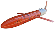
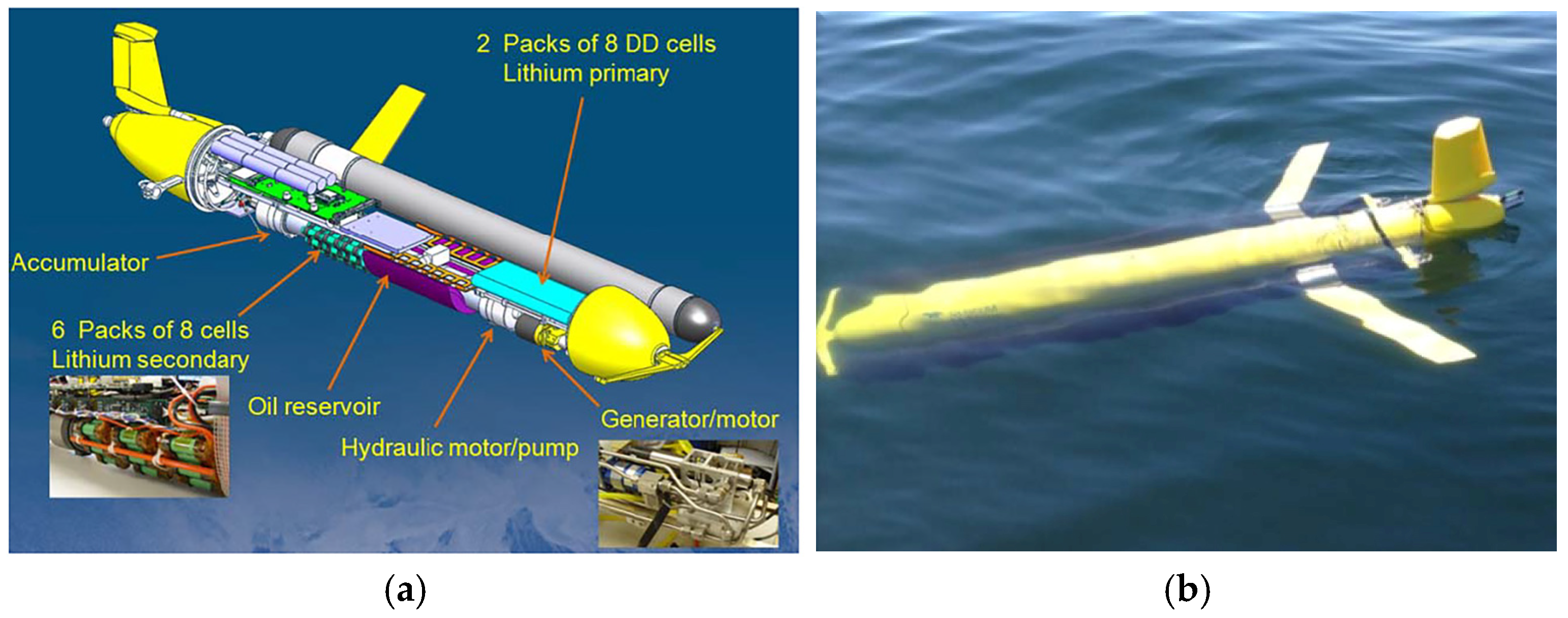
Figure 3. Underwater glider with a pressure-resistant cabin shell made of composite materials. (a) Slocum glider. Reproduced with permission from [74]. (b) SeaWing-7000.
Jmse 13 01509 g003
Figure 4. Density and compressibility of seawater with the depth. Reproduced with permission from [81]. (a) Seawater density. (b) Compressibility of seawater.
Jmse 13 01509 g004
Figure 5. Slocum glider compressibility. Reproduced with permission from [69].
Jmse 13 01509 g005
Figure 6. Collaborative Hierarchical Optimization Design Method. Reproduced with permission from [85]. (a) The flow chart of the overall design of optimization. (b) Comparison of hoop and axial stress-strain results of the shell obtained by a test. (c) Comparison of results obtained by FEM analysis and test.
Jmse 13 01509 g006
Figure 7. Slocum “RU27”. Reproduced with permission from [86].
Jmse 13 01509 g007
Figure 11. Principle of the hydraulic compensation system. (a) The LRUGs dives from the surface and the condition. (b) When the pressure is higher than precharge pressure. (c) When the pressure is higher than the maximum working pressure of the spring accumulator. (d) When the pressure is higher than the maximum working pressure. Reproduced with permission from [101].
Jmse 13 01509 g011
Figure 12. SMA-BHE in its (a) cold and (b) hot configurations with (c) water ports. Reproduced with permission from [95].
Jmse 13 01509 g012
Figure 13. SMA-BHE position vs. temperature results comparison with simulation. Reproduced with permission from [95].
Jmse 13 01509 g013
Figure 14. Schematic diagram of the Slocum Thermal buoyancy Engine. (a) Equilibrium conditions at surface before descent. (b) Descent with heat flow to water. (c) Beginning of ascent. (d) Ascent, heat flowing from water, returned to equilibrium as in (a). Reproduced with permission from [105].
Jmse 13 01509 g014
Figure 15. Slocum Thermal E-Twin glider. Reproduced with permission from [106]. (a) Internal structure layout diagram. (b) Physical diagram of the entire machine.
Jmse 13 01509 g015
Figure 16. The schematic of the new-type thermal buoyancy engine. Reproduced with permission from [107].
Jmse 13 01509 g016
Figure 17. Dual-mode operation diagram. Reproduced with permission from [107]. (a) Energy harvesting mode. (b) The gliding mode.
Jmse 13 01509 g017
Figure 18. Schematic of biofilm inhibition showing the effects of surface-engineered nanomaterials with diverse antimicrobial properties. Reproduced with permission from [114].
Jmse 13 01509 g018
Figure 19. Thermal conductivity (a) and electrical resistivity. (b) of PA and PA/HGA. Reproduced with permission from [117].
Jmse 13 01509 g019
Table 2. Material performance parameters. Reproduced with permission from [63].
ParametersAluminum
Alloy
Titanium
Alloy
Carbon
Fiber
Glass
Fiber
E1 (E)/GPa7111012038.6
E2/GPa 7.38.3
G12 (G)/GPa27.641.95.94.4
G13/GPa 5.94.4
G23/GPa 3.02.1
ν12 (ν)0.330.330.320.14
ρ/(g·cm−3)2.704.511.651.85
σs/MPa290890
Xc/MPa 1010700
Table 3. Parameter comparison between the buoyancy adjustment methods of the SMA actuator and pump. Reproduced with permission from [104].
ParameterSMA ActuatorPump
Driving voltage (V)524
Driving current (A)8.41.0
Input power (w)4224
Maximum adjustment rate (mL/s)12.5
Minimum adjustment volume (mL)12.5
Table 4. Summary of the characteristics of typical buoyancy-driven propulsion technologies for underwater gliders.
TypeEnvironmental Dependence and ControllabilityEnergy DemandAdvantagesDisadvantagesTypical Applications
Active hydraulic drive [28,96]Independent of environment; fully controllableHigh (Dependent on battery for continuous function)Response speed is fast (in milliseconds)High energy consumptionSlocum, Spray, Seaglider
Passive compensation mechanism [100]Driven by environmental pressure; non-controllableExtremely low (no external energy input required)reduces system energy consumption.Slow response Deepglider
SMAs drive [95,104]Triggered by environmental conditions, controllableLow (temperature difference in the ocean)
High (electrical energy for heating)
High response speed
(second-level)
Limited fatigue lifeLaboratory prototype (SMA-BHE)
Thermal energy drive [106,107]Triggered by environmental conditions, controllableLow (temperature difference in the ocean)energy-autonomous missionsEnergy conversion efficiency is relatively lowSlocum Thermal E-Twin
Disclaimer/Publisher’s Note: The statements, opinions and data contained in all publications are solely those of the individual author(s) and contributor(s) and not of MDPI and/or the editor(s). MDPI and/or the editor(s) disclaim responsibility for any injury to people or property resulting from any ideas, methods, instructions or products referred to in the content.