1. Introduction
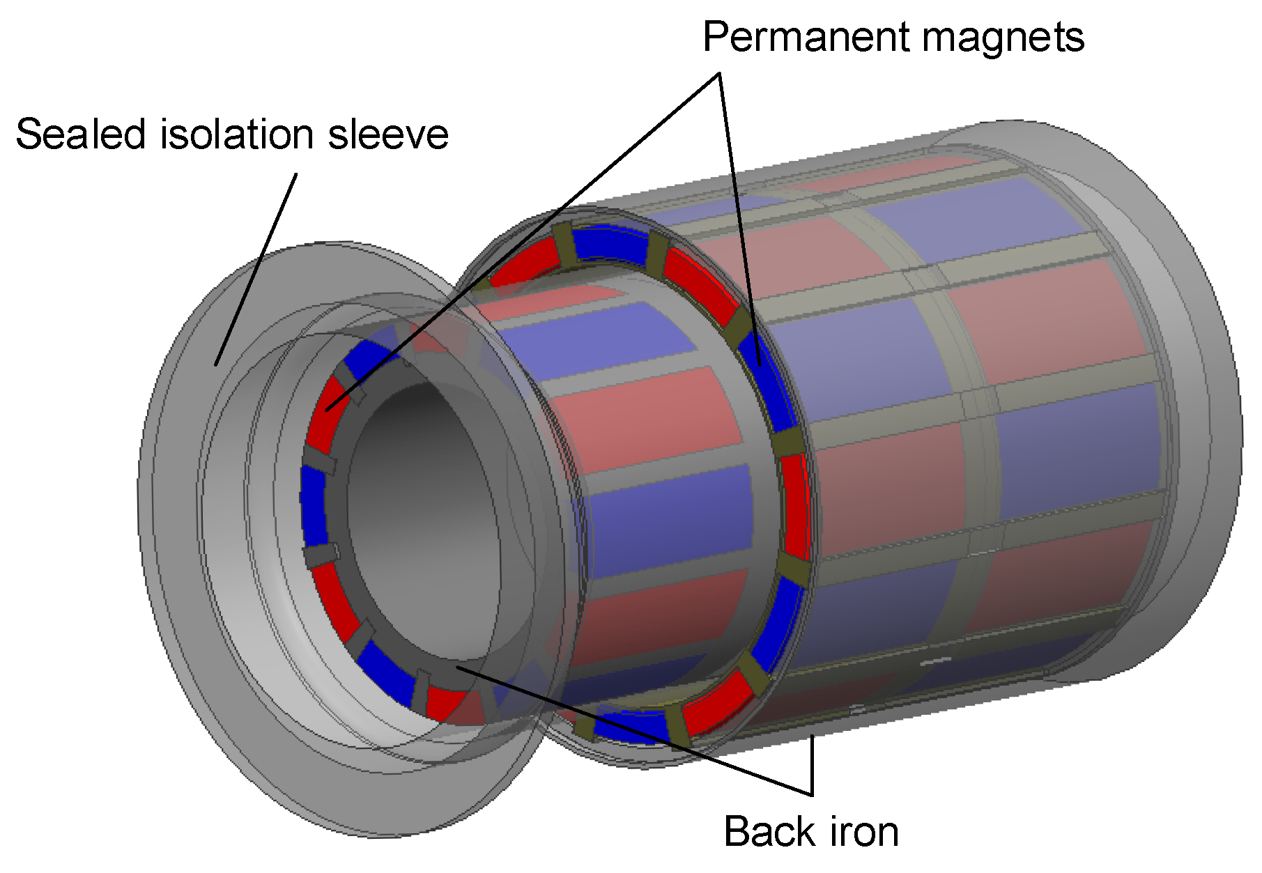
Permanent magnetic couplings (PMCs), as illustrated in
Figure 1, enable contactless torque transmission through radially polarized alternating magnets mounted on concentric inner (input) and outer (output) rotors. A sealed isolation sleeve fully decouples both rotors, achieving zero leakage and strict static sealing—a critical advantage for marine energy systems operating in corrosive, high-pressure environments.
Owing to their hermetic transmission capabilities, PMCs are indispensable in offshore applications, including ocean energy harvesting, deep-sea propulsion, and subsea processing. For instance, compact PMCs have resolved sealing challenges and improved the energy transfer efficiency in low-velocity ocean current energy harvesters [
1], while thruster designs incorporating magnetic isolation sleeves have enhanced deep-sea propulsion reliability [
2]. Permanent magnet couplings applied in underwater propulsion achieve 40 Nm torque transmission [
3]. Since the maximum transferable torque determines the power capacity of marine current generators, the optimization of permanent magnet charging methods has been pursued [
4,
5]. Despite these advances, conventional PMCs face critical limitations: the torque capacity is typically constrained below 100 Nm [
6], restricting high-power deployments; resilience to extreme pressure, corrosion, and sustained operation remains inadequate; and significant eddy current losses during continuous operation reduce the transmission efficiency.
While analytical PMC models (e.g., Maxwell equation-based approaches [
7,
8,
9]) provide physical insights, their computational complexity escalates rapidly with harmonic considerations. Although 3D finite element analysis (FEA) provides accuracy [
10], its resource intensity hinders iterative optimization. Magnetic equivalent circuit (MEC) models present a practical alternative but suffer from accuracy degradation in large-air-gap scenarios, which are common in pressure-resistant designs [
11]. Recent MEC refinements address 2D flux distortion [
12] or employ 3D flux tube segmentation [
13]; however, 3D leakage flux and axial end-effects in large-air-gap configurations remain inadequately resolved.
To address these limitations, a ceramic isolated PMC is proposed for deep-sea cryogenic ammonia submersible pumps. This innovation delivers three key advances: environmental robustness—ceramic sleeves enable static sealing under combined low-temperature, high-pressure, and acid/alkali corrosion conditions; enhanced torque transport ability—they target torque transmission of 900 Nm; and computationally efficient optimization. The Taguchi method is adopted as the optimization framework due to its demonstrated efficacy in electromagnetic device design. Taguchi orthogonal arrays substantially reduce experimental costs—as demonstrated in [
14], which reported an 80% reduction in trials for five-level three-factor optimizations of a magnet motor. This efficiency is critical for multi-parameter PMC systems. The method systematically resolves parameter interactions [
15] and quantifies influence priorities via signal-to-noise ratios and variance analysis [
16], thereby clarifying the optimization focus. Furthermore, its compatibility with analytical models accelerates multi-objective convergence [
17], enabling efficient integration with our 3D MEC approach.
In this work, an equivalent magnetic circuit model was established, taking into account three-dimensional magnetic leakage and axial end-effects. Compared with previous models, it can more accurately describe the magnetic field distribution under large air gaps. Through the developed MEC–Taguchi optimization strategy, key design parameters were optimized to maximize torque transmission, achieving a 21% torque density gain. Experimental validation confirmed the superior performance of the optimized coupler, achieving torque transmission of 920 Nm. The whole-machine test verified the stability of the PMC’s torque transfer capabilities. These contributions establish a new design paradigm for high-power, leakage-free drivetrains in corrosive deep-sea applications.
2. Ceramic Isolation
Conventional PMC isolation sleeves, typically fabricated from conductive metals such as austenitic stainless steel or titanium alloys, incur significant eddy current losses—a critical limitation for high-speed or high-power applications. While hybrid designs (e.g., titanium inner sleeves with carbon fiber composites [
18]) or neural network-based parameter optimization [
19] can reduce these losses (by 66.4% and 3.71%, respectively), substantial energy dissipation persists. For instance, eddy current losses in stainless steel sleeves reach 71 W, while lower-conductivity alternatives like titanium or aluminum alloys still exhibit losses exceeding 30 W [
20]. These losses not only reduce the efficiency but also generate detrimental heat during prolonged operation, compromising reliability in demanding environments such as deep-sea pumps or thrusters.
To fundamentally resolve this issue, a ceramic isolation sleeve is proposed. Ceramics exhibit near-zero electrical conductivity, effectively eliminating eddy current losses—a prerequisite for high-speed PMC operation. Furthermore, ceramics provide exceptional corrosion resistance in acidic/alkaline marine environments, surpassing the capabilities of polymeric alternatives. However, the inherent ceramic brittleness necessitates structural thickening to withstand deep-sea pressures. Through rigorous ANSYS 2025 R2 mechanical analysis, a 6 mm sleeve thickness was determined to ensure structural integrity under 3.5 MPa hydrostatic pressure (simulating deep-sea conditions), with the maximum stress limited to 100 MPa—well below the fracture strength of the selected high-performance ceramic. Additionally, a 10 mm operational air gap was implemented to accommodate rotational misalignment, prevent friction, and facilitate permanent magnet installation.
3. Equivalent Magnetic Circuit Considering Magnetic Leakage
3.1. Assumptions and Definitions
Figure 2a illustrates a radial view of one pole pair of the PMC expanded along the mean radius. To optimize torque generation, the magnetic circuit is conceptualized with a permanent magnet angle difference of 1/2 pole pair between the inner and outer axes.
Due to structural constraints, the outermost ring radius (
) is fixed at 137 mm, and
is set to 110 mm. To prevent back iron saturation, the back iron thickness is assumed equal to the magnet thickness. The isolation sleeve thickness limitation restricts the operational air gap to
mm. Initial parameters including the duty cycle (
, ratio of magnet arc length
to intermagnet space
), pole pairs (
p), and magnet thickness (
) are specified in
Table 1, with other parameters derived accordingly.
3.2. Equivalent Magnetic Circuit Analysis
As depicted in
Figure 2, the outermost magnetic circuit constitutes the primary flux path. Leakage flux comprises two components: edge leakage extending from one pole to the back iron (terminating at the opposite pole) and pole-to-pole leakage between adjacent permanent magnet surfaces. The magnetic path in
Figure 2a is represented by the equivalent electromagnetic circuit in
Figure 2b, with each component analyzed below.
3.2.1. Leakage Flux
Edge leakage permeances, as shown in
Figure 3b, are computed using boundaries defined by parallel tube and semicircular cylinder configurations to minimize the flux paths [
21]. The magnet-to-iron leakage permeance is calculated as
where
= min
. Infinite back iron permeability is assumed, neglecting magnetic resistance in the flux path.
The radial envelope of the pole-to-pole leakage flux (
Figure 3a) is approximated with leakage length
min
. The adjacent PM permeance is given by
3.2.2. Leakage at End of PM
Significant flux leakage occurs at the permanent magnet ends [
22], as shown in
Figure 4. Compared to circumferential sections, substantial Z-direction components are observed at the axial ends. The end-leakage reluctance, expressed as
,
, can be approximately calculated as
Axial end-leakage flux exists at both PM ends (
Figure 5a), contributing to pole-to-pole leakage resistance. The flux path can be deduced from two components [
13]:
Another part, distributed longitudinally, contributes to the main flux, as shown in
Figure 5b. Instead of being distributed in the
plane, this magnetic flux is distributed in the axial plane. Although magnetic flux does not only exist in these two planes, analysis in two vertical planes can take full account of the magnetic flux path. The axial flux path reluctance can be calculated by the formula
3.2.3. Magnetic Circuit Model Analysis
According to the principle of the magnetic equivalent circuit, the air gap reluctance
, the self-reluctance of the magnet
, and the magnetomotive force
F are calculated as follows:
Considering the symmetry in the construction, we can obtain the entire equivalent magnetic circuit by connecting the calculated magnetoresistance in series. However, the circuit shown in
Figure 2b is too complex for analysis. Therefore, it is simplified by combining analogous magnetic circuits. The flux path analysis of the equivalent magnetic circuit, originating from the N pole of the magnet and traversing three types of magnetoresistance toward its own, neighboring, and opposite S poles, allows for the simplification of the reluctances between the flux paths as
,
,
, respectively. The circuit is then further simplified by combining these three types of resistance, as shown in
Figure 6a. The resulting simplified magnetic circuit is illustrated in
Figure 6b and will be used for the analysis of the magnetic flux and torque transmission.
3.3. Formulation of Developed Torque
By analyzing the simplified equivalent magnetic loop in
Figure 6b, we can determine the average edge flux leakage
, pole-to-pole leakage
, and effective flux
contributing to torque transmission in the magnetic coupling. The air gap magnetic flux density
B is calculated from the ratio of the effective magnetic flux
to the area of the permanent magnets opposite to each other. Here, the main flux path is obtained as follows:
By solving the above equivalent magnetic circuit equation, the average magnetic flux density of a single magnetic block can be expressed as
The magnetic field energy of the permanent magnet coupling is mainly concentrated in the air gap region, and the air gap volume
V integration of the energy density yields energy. Through the virtual displacement principle, the torque generated by the magnetic field induces a virtual displacement
. The work done by this torque corresponds to the tangential magnetic field energy
. According to the principle of energy conservation, the following expressions can be obtained:
Finally, a multi-parameter analytical expression for the transmitted torque is derived by substituting the expression provided above:
4. Optimization of PMCs
4.1. Verification of Accuracy of Proposed Model
A three-dimensional model was constructed using the initial parameters in
Table 1. Torque values obtained through finite element analysis (FEA) were simulated using the Maxwell software. As depicted in
Figure 7, the torque
T from the proposed leakage-inclusive MEC model was compared against the torque
derived from a simplified circuit considering only
and
and the FEA results
. Increasing the axial length exacerbates torque calculation deviations in leakage-excluded models due to amplified end-leakage effects. Conversely, the leakage-inclusive MEC model demonstrates excellent agreement with FEA simulations.
4.2. Parameter Sensitivity Analysis
Figure 8a presents the variation in the transmitted torque with the duty cycle under different numbers of pole pairs. Under fixed outer diameter and air gap constraints, the study identified the optimal pole pair range for the Taguchi experimental parameter P as 12, 14, or 16, which yield significantly higher torque than when using lower pole counts. As the duty cycle continues to increase, the spaces between permanent magnets
decrease, resulting in more magnetic flux leakage. Thus, the experimental parameter A, which represents the duty cycle, is chosen to be around 0.8 to achieve the maximum torque with different numbers of pole pairs.
The magnet thickness (parameter L) critically influences the magnetic force and leakage flux magnitude.
Figure 8b shows that the torque increases with thicknesses below 14 mm but declines beyond this point, as the magnetic circuit becomes saturated as the magnet thickness increases. Moreover, increased shape errors in cuboid magnets reduce the effective volume and increase leakage. Thus, the magnet thickness should not exceed 16 mm.
4.3. Optimization of Torque Characteristics Based on MEC–Taguchi Method
Torque variations with respect to sensitive parameters were analyzed using the equivalent magnetic circuit model. Based on this analysis, the ranges of parameters A, P, and L were determined. The corresponding experimental data are presented in
Table 2. We choose the torque and torque density (TRV) as the optimization objectives for the coupling. TRV is an important measure of performance; it refers to the torque that can be output per unit volume
, allowing the device to have a higher output capacity under limited space constraints.
After preparing the initial parameters, a Taguchi orthogonal experimental table was generated, as shown in
Table 3, to ensure that the number of columns in the array covered all variables. In this table, the rows represent the number of experiments, and the columns represent the factor levels employed in the experiments. The optimization objective is to select the optimal parameter combination to achieve a larger transmission torque and higher torque density (TRV). The last two columns show the coupling performance parameters obtained for each experimental group.
In order to investigate the magnitude of the effects of each factor on the performance of the coupling, the sum of squares (SS) is calculated; the larger it is, the greater the effect of the factor on the performance.
represents the performance value at the
j-th level of the
p-th factor, and
is the mean value of the experimental results across all levels [
23].
Table 4 shows that factor P has the largest effect on the transmission torque and factor L has the largest effect on the torque density.
Figure 9 presents the output graphs for different levels of each factor. From these graphs, the variations in the responses of the torque and torque density to each factor can be obtained, and the optimal factor levels can be intuitively observed.
An interactive influence effect of the number of pole pairs and the duty cycle exists on the transmission torque and torque density. We calculate the average torque values
and
at each level, as well as the average torque value
for each combination of levels. The interactive influence effects
for all combinations are calculated and presented in
Table 5,
The maximum and positive value of
implies a synergistic effect of this combination in terms of increasing the transport torque. Similarly, the interactive impacts of factors A and B on the torque density, presented in
Table 6, also result in the largest
, indicating that this combination has a positive impact in improving the torque density.
4.4. Discussion
The MEC–Taguchi optimization method provides a systematic way to optimize multiple parameters, enabling one to balance different performance requirements.
Table 7 compares the parameters and performance before and after optimization. The torque density experiences a
enhancement after optimization. Less permanent magnet materials for torque transmission lead to an improvement in economic efficiency.
A functional prototype was manufactured based on the parameters derived from the MEC–Taguchi optimization (
Figure 10). Rigorous torque testing was conducted using a dedicated dynamometer under an isolated PMC; the prototype achieved a maximum torque of 920 Nm before active–passive rotor slippage occurred. The maximum torque was lower than the calculated result, with the deviation mainly stemming from two aspects. Firstly, there are inherent inaccuracies in the geometric shape of the permanent magnet and its magnetization characteristics. Secondly, mechanical losses inevitably occur during the practical measurement process, both of which contributed to the observed reduction in the torque test outcome.
After confirming the deep-sea sealing reliability through 3.5 MPa hydrostatic pressure and 7 bar helium leak tests (<1.0 × 10
−6 scc/sec), the PMC was coupled to a 250 kW electric motor and a submerged pump (
Figure 11). It sustained full-load operation for 3 h in cryogenic ammonia at −33 °C, with torque fluctuations remaining within ±2%, demonstrating robustness under simulated deep-sea conditions. The developed magnetic coupling successfully attains stable transmission performance; characterized by a large air gap and high torque capacity, this represents a significant advancement in the realms of static seal transmission and torque-limiting functionalities.
5. Conclusions
This paper focuses on the analysis of a PMC with a ceramic isolation sleeve featuring strong environmental adaptability, addressing the problem whereby traditional isolation sleeve materials have large eddy current losses and cannot meet the transmission requirements of high-power equipment.
Traditional isolation sleeve materials suffer from significant eddy current losses. In contrast, the ceramic isolation sleeve, due to its extremely low electrical conductivity, effectively overcomes this issue. It is particularly suitable for high-speed rotating magnetic coupling devices. Moreover, ceramic materials have high strength, corrosion resistance, and strong environmental adaptability, enabling the equipment to be applied in fields such as deep-sea exploration and the petroleum industry.
A 3D magnetic equivalent circuit (MEC) model explicitly accounting for leakage flux and axial end-effects was developed, enabling accurate large-air-gap field characterization. Validation confirmed that there was a less than 5% deviation from the FEA results. An expression for the multi-parameter transmission torque was derived, providing a theoretical basis for subsequent optimization.
By comparing the model considering magnetic flux leakage with the finite element results and the model without such considerations, the accuracy of the proposed equivalent magnetic circuit model was verified. Based on the analysis of the MEC model, the value ranges of the duty cycle, the number of pole pairs, and the thickness of the permanent magnet were determined. The Taguchi method was employed for combined parameter optimization, resulting in a 21% increase in torque density. The optimized coupling demonstrated excellent performance in experiments. Although the measured torque was lower than the calculated value, it still achieved stable transmission with a large air gap and high torque.
This study provides an effective method for the optimization of PMCs with a large air gap, makes significant progress in static seal transmission and torque limitation, and promotes applications in complex environments such as deep-sea and deep-well pumps. Future research can consider more complex actual working conditions and refine the structure to further improve the performance and adaptability of PMCs.
Author Contributions
L.S., X.G. and Y.L. conceived the study and established the analytical method; L.S. and X.G. analyzed the analytical results; L.S. wrote the manuscript; X.G. and Y.L. reviewed and edited the manuscript. All authors have read and agreed to the published version of the manuscript.
Funding
This research was funded by the National Science Foundation of China, grant number 12472050.
Data Availability Statement
The processed data required to reproduce these findings is part of my ongoing study. For verification of the accuracy of the data included in this study, please contact the corresponding author to obtain it.
Conflicts of Interest
The authors declare no conflicts of interest.
References
- Huang, L.; Lyu, F. Compact low-velocity ocean current energy harvester using magnetic couplings for long-term scientific seafloor observation. J. Mar. Sci. Eng. 2020, 8, 410. [Google Scholar] [CrossRef]
- Li, Y.; Hu, Y.; Song, B.; Mao, Z. Study on static characteristics of a novel deep-sea motor thruster. In Proceedings of the 2018 21st International Conference on Electrical Machines and Systems (ICEMS), Jeju, Republic of Korea, 7–10 October 2018; pp. 126–131. [Google Scholar]
- Li, Y.; Hu, Y.; Guo, Y.; Song, B.; Mao, Z. Analytical modeling and design of novel conical halbach permanent magnet couplings for underwater propulsion. J. Mar. Sci. Eng. 2021, 9, 290. [Google Scholar] [CrossRef]
- Li, Y.; Hu, Y.; Song, B.; Mao, Z.; Tian, W. Performance analysis of conical permanent magnet couplings for underwater propulsion. J. Mar. Sci. Eng. 2019, 7, 187. [Google Scholar] [CrossRef]
- Zhong, W.; Mao, Z.; Tian, W.; Li, Y. Design and performance analysis of trapezoid halbach array magnetic couplings for ocean current turbine generator. In Global Oceans 2020: Singapore—U.S. Gulf Coast; IEEE: Piscataway, NJ, USA, 2020; pp. 1–5. [Google Scholar]
- Park, J.; Paul, S.; Chang, J.; Hwang, T.; Yoon, J. Design and comparative survey of high torque coaxial permanent magnet coupling for tidal current generator. Int. J. Electr. Power Energy Syst. 2020, 120, 105966. [Google Scholar] [CrossRef]
- Dolisy, B.; Mezani, S.; Lubin, T.; Lévêque, J. A new analytical torque formula for axial field permanent magnets coupling. IEEE Trans. Energy Convers. 2015, 30, 892–899. [Google Scholar] [CrossRef]
- Lubin, T.; Mezani, S.; Rezzoug, A. Analytical computation of the magnetic field distribution in a magnetic gear. IEEE Trans. Magn. 2010, 46, 2611–2621. [Google Scholar] [CrossRef]
- Fontchastagner, J.; Lefevre, Y.; Messine, F. Some co-axial magnetic couplings designed using an analytical model and an exact global optimization code. IEEE Trans. Magn. 2009, 45, 1458–1461. [Google Scholar] [CrossRef]
- Arslan, S.; Iskender, I.; Navruz, T.S. Fem-based optimal design and testing of synchronous magnetic coupling for aerospace starter/generator applications. Eng. Sci. Technol. Int. J. 2023, 41, 101403. [Google Scholar] [CrossRef]
- Xikang, C.; Wei, L.; Yang, Z.; Sitong, L.; Weiqi, L. A concise transmitted torque calculation method for pre-design of axial permanent magnetic coupler. IEEE Trans. Energy Convers. 2020, 35, 938–947. [Google Scholar] [CrossRef]
- Wang, J.; Zhu, J. A simple method for performance prediction of permanent magnet eddy current couplings using a new magnetic equivalent circuit model. IEEE Trans. Ind. Electron. 2018, 65, 2487–2495. [Google Scholar] [CrossRef]
- Sun, K.; Shi, J.; Cui, W.; Meng, G. Theoretical computational model for cylindrical permanent magnet coupling. Electronics 2021, 10, 2026. [Google Scholar] [CrossRef]
- Wang, S.; Wang, Y.; Liu, C.; Lei, G.; Zhu, J.; Guo, Y. Detent force minimization of a tubular flux-switching permanent magnet motor using un-equal width stator slots based on taguchi method. IEEE Trans. Appl. Supercond. 2020, 30, 5202505. [Google Scholar] [CrossRef]
- Sharma, U.; Singh, B. Design and development of energy efficient single phase induction motor for ceiling fan using taguchi’s orthogonal arrays. IEEE Trans. Ind. Appl. 2021, 57, 3562–3572. [Google Scholar] [CrossRef]
- He, J.; Li, G.; Zhou, R.; Wang, Q. Optimization of permanent-magnet spherical motor based on taguchi method. IEEE Trans. Magn. 2020, 56, 8200107. [Google Scholar] [CrossRef]
- Sun, X.; Shi, Z.; Zhu, J. Multiobjective design optimization of an ipmsm for evs based on fuzzy method and sequential taguchi method. IEEE Trans. Ind. Electron. 2021, 68, 10592–10600. [Google Scholar] [CrossRef]
- Fang, H.; Li, D.; Qu, R.; Li, J.; Wang, C.; Song, B. Rotor design and eddy-current loss suppression for high-speed machines with a solid-pm rotor. IEEE Trans. Ind. Appl. 2019, 55, 448–457. [Google Scholar] [CrossRef]
- Wang, D.; Niu, B.; Pan, P.; Sun, G. Multi-objective optimization design of permanent magnet eddy current coupler based on scg-bp neural network modeling and the ondx-nsga-ii algorithm. Actuators 2023, 12, 367. [Google Scholar] [CrossRef]
- Mao, Y.; Cai, L.; Chertovskih, R.; Guo, W.; Wang, X. One-way thermomagnetic simulation of magnetic coupling in natural gas pressure energy utilization. Eng. Appl. Comput. Fluid Mech. 2024, 18, 269207150. [Google Scholar] [CrossRef]
- Hanselman, D. Brushless Permanent Magnet Motor Design; The Writers’ Collective: Amsterdam, The Netherlands, 2003. [Google Scholar]
- Zhu, L.-L.; Xu, D.; Li, Q.; Sun, W.; Hu, Y.-Q. Analysis and optimization of equivalent magnetic circuit model for a hybrid axial field flux-switching permanent magnet machine. In Proceedings of the 2018 21st International Conference on Electrical Machines and Systems (ICEMS), Jeju, Republic of Korea, 7–10 October 2018; pp. 407–412. [Google Scholar]
- Zhang, G.; Tao, J.; Li, Y.; Hua, W.; Xu, X.; Chen, Z. Magnetic equivalent circuit and optimization method of a synchronous reluctance motor with concentrated windings. Energies 2022, 15, 1735. [Google Scholar] [CrossRef]
| Disclaimer/Publisher’s Note: The statements, opinions and data contained in all publications are solely those of the individual author(s) and contributor(s) and not of MDPI and/or the editor(s). MDPI and/or the editor(s) disclaim responsibility for any injury to people or property resulting from any ideas, methods, instructions or products referred to in the content. |
© 2025 by the authors. Licensee MDPI, Basel, Switzerland. This article is an open access article distributed under the terms and conditions of the Creative Commons Attribution (CC BY) license (https://creativecommons.org/licenses/by/4.0/).


