Abstract
This paper presents a behavior tree-based control architecture for end-to-end mission planning of an autonomous underwater vehicle (AUV) collaborating with a moving mothership in dynamic marine environments. The framework is organized into three phases—prepare and launch, execute the mission, and retrieval and docking—each encapsulated in an independent sub-tree to enable modular error handling and seamless phase transitions. The AUV and mothership operate entirely underwater, with real-time docking to a moving platform. An extended Kalman filter (EKF) fuses data from inertial, pressure, and acoustic sensors for accurate navigation and state estimation. At the same time, obstacle avoidance leverages forward-looking sonar (FLS)-based potential field methods to react to unpredictable underwater hazards. The system is implemented on the robot operating system (ROS) and validated in the Stonefish physics engine simulator. Simulation results demonstrate reliable mission execution, successful dynamic docking under communication delays and sensor noise, and robust retrieval from injected faults, confirming the validity and stability of the proposed architecture.
1. Introduction
In recent years, autonomous underwater vehicles (AUVs) have played an important role in marine robotics for various missions, including seafloor topographic surveys, resource exploration, and environmental monitoring [1,2,3]. However, AUVs have limited underwater communication bandwidth and range in real-world marine environments and are frequently exposed to environmental uncertainties [4] such as rapidly changing currents and unpredictable obstacles [5]. As a result, AUVs cannot rely solely on teleoperation and require a high degree of autonomy to resolve unexpected situations independently. System robustness and versatility are essential, especially for AUVs operating in remote waters. A focus has been operationalizing the pre-mission cycle, including AUV launch and retrieval, through collaboration with the mothership [6]. Launching an AUV from a mothership and recovering it after the mission offers significant benefits in terms of increased operational radius, remote support, and refueling [7]. However, docking an AUV to a moving mothership presents complex challenges [8], including difficulties in relative position estimation, collision risk due to simultaneous movement, communication delays, and sensor noise [9,10,11].
Behavior trees (BTs) are emerging as an effective control technique for these complex mission environments [12]. BTs have the advantage of being highly modular and scalable and can easily express complex decisions in a clear hierarchical structure [13]. In particular, fallback, sequence, and condition nodes can be utilized to handle exceptions on the fly and support flexible path re-planning in highly uncertain maritime environments [14]. However, existing studies mainly focus on static situations such as solo mission execution or collaboration with a stationary mothership, and there is a lack of research considering cooperative operation with a moving mothership. Therefore, this research proposes implementing a behavior tree-based architecture for cooperative missions between a moving mothership and an AUV, enabling consistent and integral responses to various exceptional situations.
In this paper, we leverage the advantages of modularity and scalability of behavioral trees to address a mothership–AUV collaboration scenario in a marine environment, proposing a modularized control structure that clearly distinguishes three phases: launch, mission, and retrieval, including situations where an AUV docks with a moving ship. Each phase comprises independent sub-trees, which allows us to design the error handling of sudden situations and the transition process between phases. Additionally, an extended Kalman filter (EKF) is employed for precise navigation and position estimation of the AUV. At the same time, a potential field technique based on forward-looking sonar (FLS) is employed for obstacle avoidance, enabling more efficient and safe path planning. The proposed architecture was experimentally validated through simulations using the robot operating system (ROS) and Stonefish, a physics engine-based simulator, to verify its validity and stability. The highlights of this paper are as follows.
- We propose a modular behavior tree-based framework that enables seamless end-to-end mission planning (launch, execution, retrieval, and dynamic docking) for cooperative operations between a moving mothership and an AUV in dynamic marine environments.
- Each mission phase is implemented as an independent sub-tree, allowing for robust error handling and smooth phase transitions.
- Standard localization and obstacle avoidance methods (EKF and FLS-PF) are integrated as modular components, ensuring future extensibility with minimal redesign.
- The proposed system is validated in realistic simulation scenarios (ROS, Stonefish), demonstrating reliable performance and resilience in the presence of communication delays, sensor noise, and injected faults.
2. Overview of Behavior Trees and Application
2.1. Concept of Behavior Trees
A behavior tree is a hierarchical decision-making framework widely used in robotics and autonomous systems. Structured as a directed acyclic graph, a BT decomposes complex logic into modular nodes, each returning a status of Success, Failure, or Running. Parent nodes aggregate their children’s results to determine the overall behavior, enabling flexible handling of exceptions and dynamic mission requirements thanks to the tree’s inherent modularity and extensibility.
2.2. Basic Node Types
The fundamental node types are sequence, fallback (selector), parallel, action, condition, and decorator. Action and condition nodes directly interact with the robot (issuing actuator commands or checking sensors). Sequence, fallback, parallel, and decorator nodes are parents that propagate a periodic tick from the top child downward, deciding their status by combining the children’s results according to the rules summarized in Table 1. Tick frequency can be tuned to meet responsiveness and computational constraints.

Table 1.
Behavior tree node characteristics.
A BT tick starts at the root, flows downward through these node types, and returns upward once all necessary children have been evaluated. The following paragraphs and figures explain each node in turn.
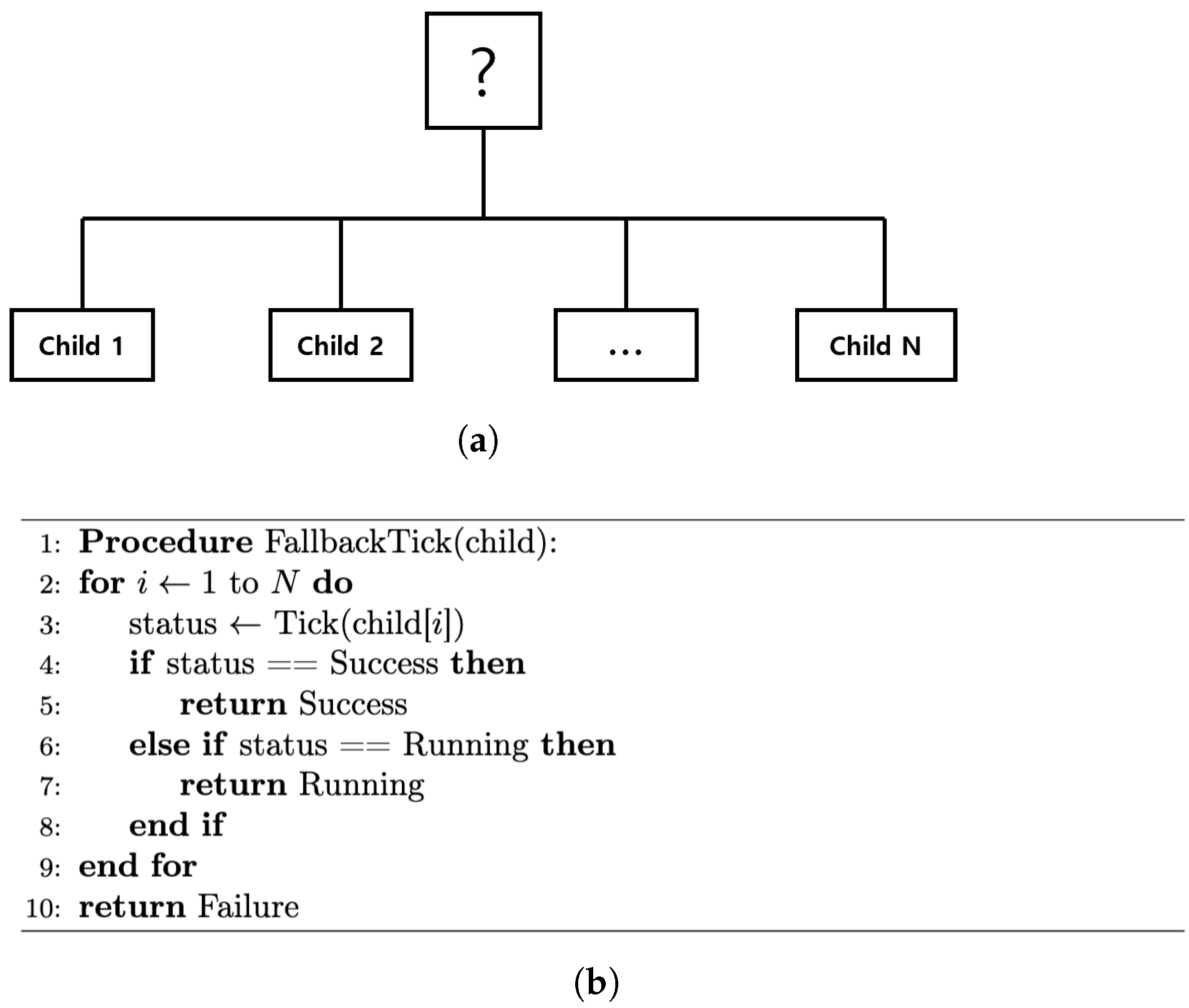
Figure 1a shows a fallback node that ticks its children from left to right. It returns Success at the first successful child, Running if a child is still executing, and Failure only if every child fails. The corresponding pseudocode is given in Figure 1b.

Figure 1.
Fallback node. (a) Graphical representation with children ticked left → right until one succeeds. (b) Corresponding pseudocode.
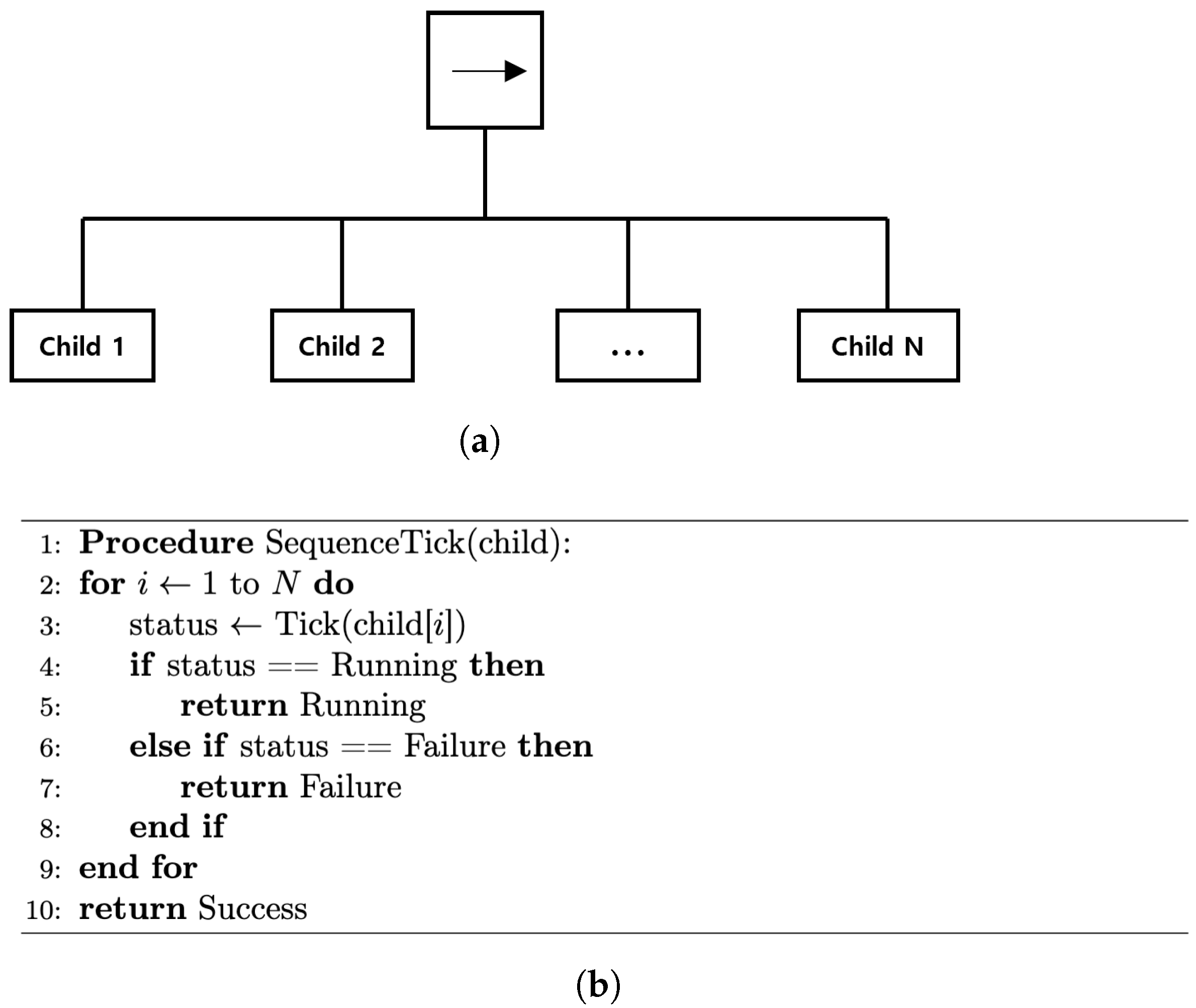
The sequence node, shown in Figure 2a, also ticks children from left to right, but returns Failure or Running immediately when encountered. It succeeds only if every child succeeds, as illustrated in Figure 2b.
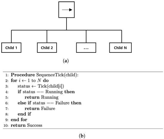
Figure 2.
Sequence node. (a) Graphical representation with children ticked left → right. (b) Pseudocode that returns Failure or Running immediately and Success only when all children succeed.
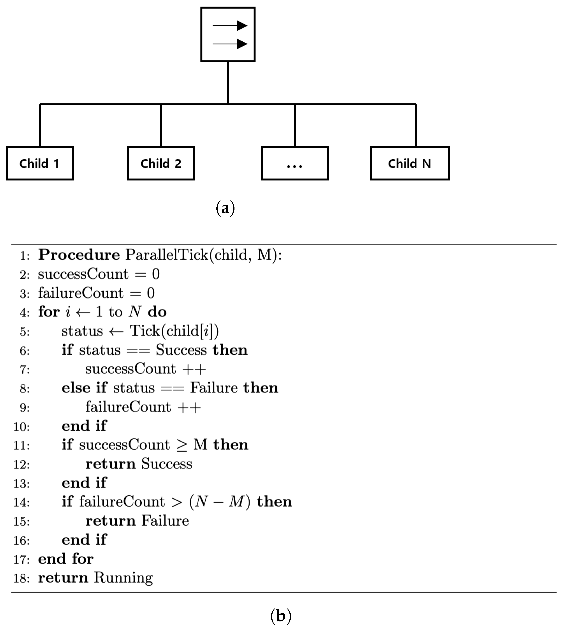
Figure 3a illustrates a parallel node that ticks all children each cycle, counting Successes and Failures. It returns Success when at least M children succeed, Failure when more than fail, and otherwise reports Running, as formalized in Figure 3b.
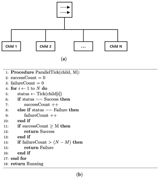
Figure 3.
Parallel node. (a) Graphical representation with all children ticked each cycle. (b) Pseudocode implementing the majority rule (M of N must succeed).
Figure 3a illustrates a parallel node that ticks all children each cycle, counting successes and failures. It succeeds when at least M children succeed, fails when more than fail, and otherwise reports Running, as formalized in Figure 3b.
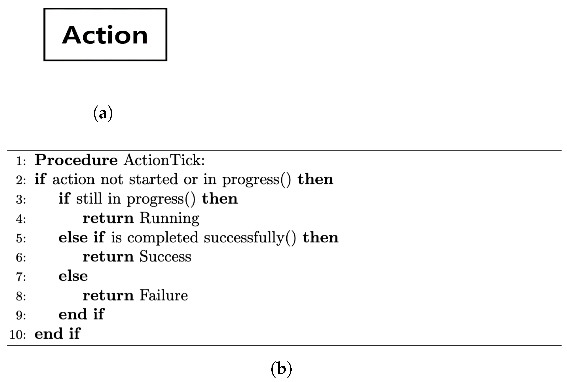
Action and condition nodes directly interface with hardware or software components. As shown in Figure 4a, an action node keeps returning Running until its task completes, then outputs Success or Failure. A condition node (Figure 5a) instantly evaluates a predicate and outputs Success or Failure (never Running); their pseudocode counterparts are given in the panels of Figure 4b and Figure 5b.

Figure 4.
Action node. (a) Symbol used in the behavior tree. (b) Pseudocode that returns Running until the action completes, then Success or Failure.
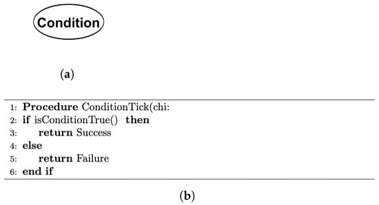
Figure 5.
Condition node. (a) Symbol used in the behavior tree. (b) Pseudocode that instantly returns Success or Failure.
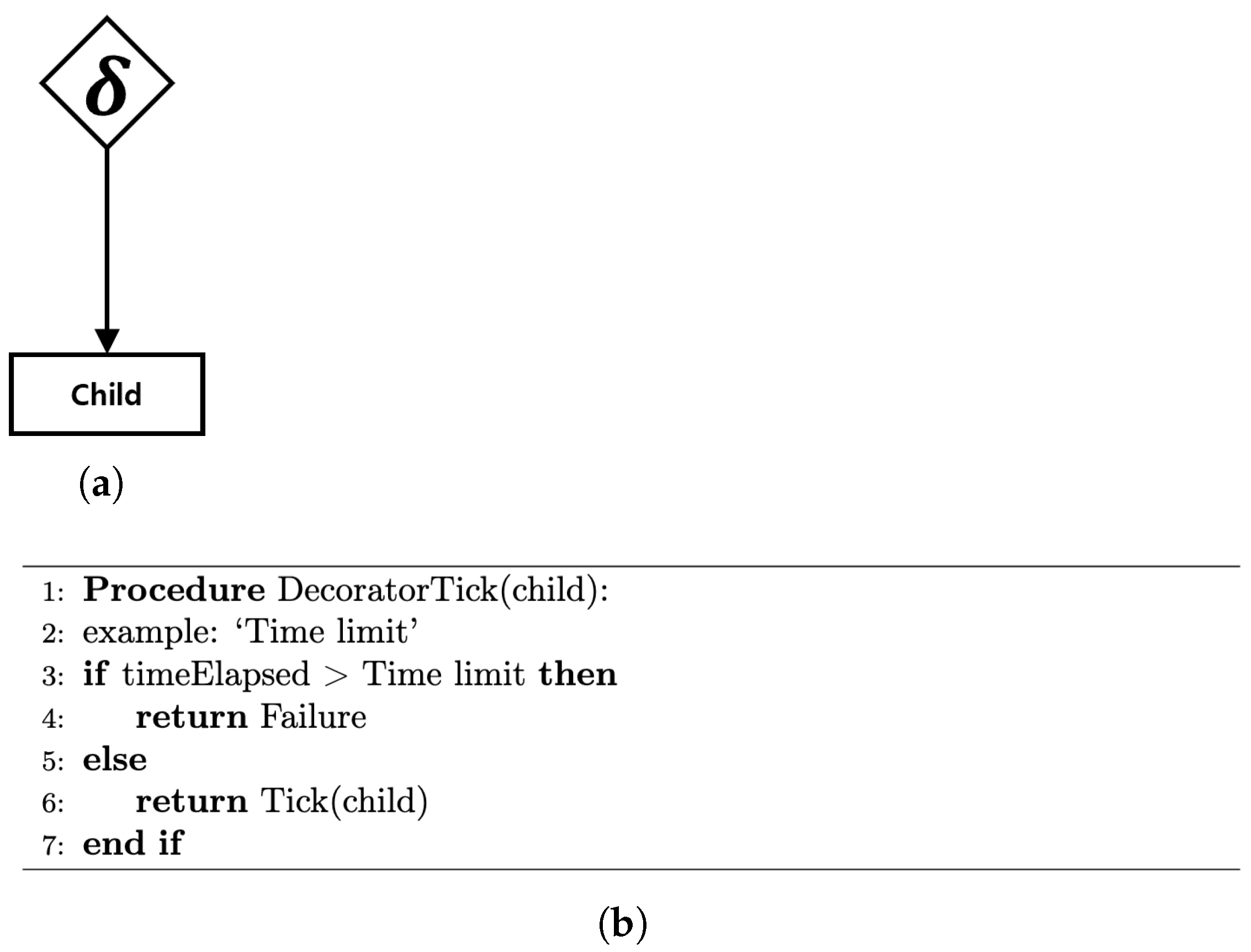
Finally, the decorator node in Figure 6a wraps a single child and alters—or simply filters—its result according to a custom rule such as timeout, inversion, or repetition. The example pseudocode in Figure 6b enforces a time limit.
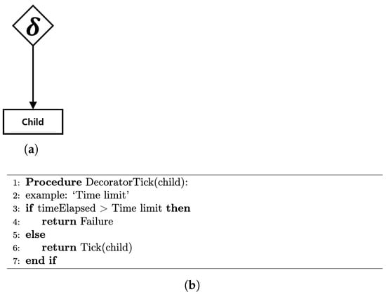
Figure 6.
Decorator node example. (a) Single-child wrapper. (b) Time-limit decorator pseudocode.
3. Methodology
3.1. Proposed Behavior Tree Structure
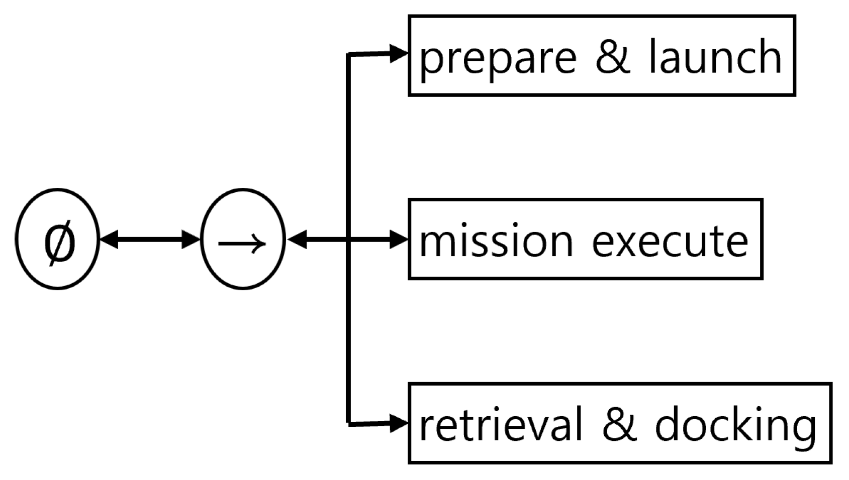
We proposed a systematic framework for the whole mission cycle of an AUV operating with a moving mothership in Figure 7. The mission is structured into three phases: prepare and launch, mission execution, and retrieval and docking. The necessary actions and conditions are organized for each phase using behavior tree sequence nodes, resulting in a robust and modular workflow.

Figure 7.
Mission phases and top-level behavior tree: prepare and launch, mission execute, and retrieval and docking.
This structure allows the AUV to safely initiate from the mothership, dynamically respond to various operational challenges, including obstacle avoidance, sensor faults, and communication interruptions, and ultimately return for retrieval. Sequence nodes ensure that all required sub-tasks within a phase are completed before the system advances to the next phase. If any task fails or remains incomplete, the system immediately triggers exception-handling procedures, guaranteeing that mission progress occurs only under safe and controlled conditions.
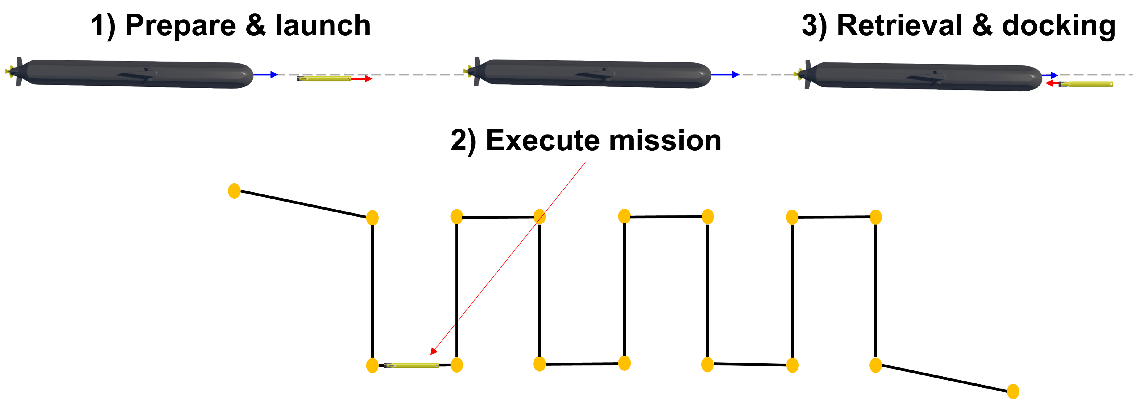
By organizing the entire operation in this way, the proposed approach provides a flexible and reliable solution for collaborative underwater missions involving multiple AUVs and complex scenarios. Figure 8 illustrates a simplified visual sequence of the AUV’s operation phases, including deployment, navigation, and retrieval. While it includes schematic 3D models, it serves as a conceptual illustration and may omit or simplify specific hardware details such as control surface configurations.
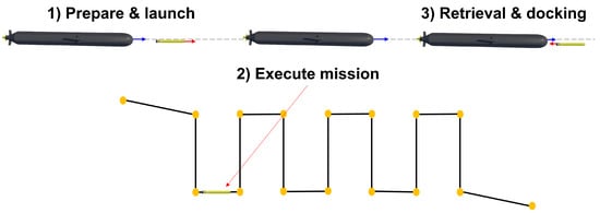
Figure 8.
Visual representation of the sequential AUV mission phases, including deployment, navigation, and retrieval.
- Prepare and launch: After deployment is initiated, the AUV separates from the mothership while maintaining a designated safe distance to prevent collision. During this phase, the AUV descends to its target depth and conducts initial system checks, including sensor diagnostics and thruster functionality. The AUV continuously monitors the relative speed and position of the moving mothership, adjusting its maneuvers accordingly to ensure a stable and controlled departure.
- Execute mission: Upon successful launch and initialization, the AUV sequentially visits multiple mission waypoints, which are indicated as yellow markers in the scenario. At each waypoint, the AUV performs various tasks, including seabed mapping, acquiring photographic data, and avoiding obstacles. Throughout this phase, the system is designed to be robust against unexpected events. Suppose anomalies such as sensor faults or communication losses are detected. In that case, the behavior tree promptly activates a dedicated safety node, enabling the AUV to reroute, temporarily suspend its mission, or initiate retrieval actions to ensure operational safety.
- Retrieval and docking: Once all waypoint tasks are completed, the AUV navigates toward the moving mothership to initiate the retrieval sequence. The AUV aligns its trajectory and speed to match those of the mothership, approaches the designated retrieval zone, and carries out docking or ingress maneuvers. The process continues until the AUV is securely recovered within the mothership, marking the end of the mission cycle.
3.1.1. Launch Preparation
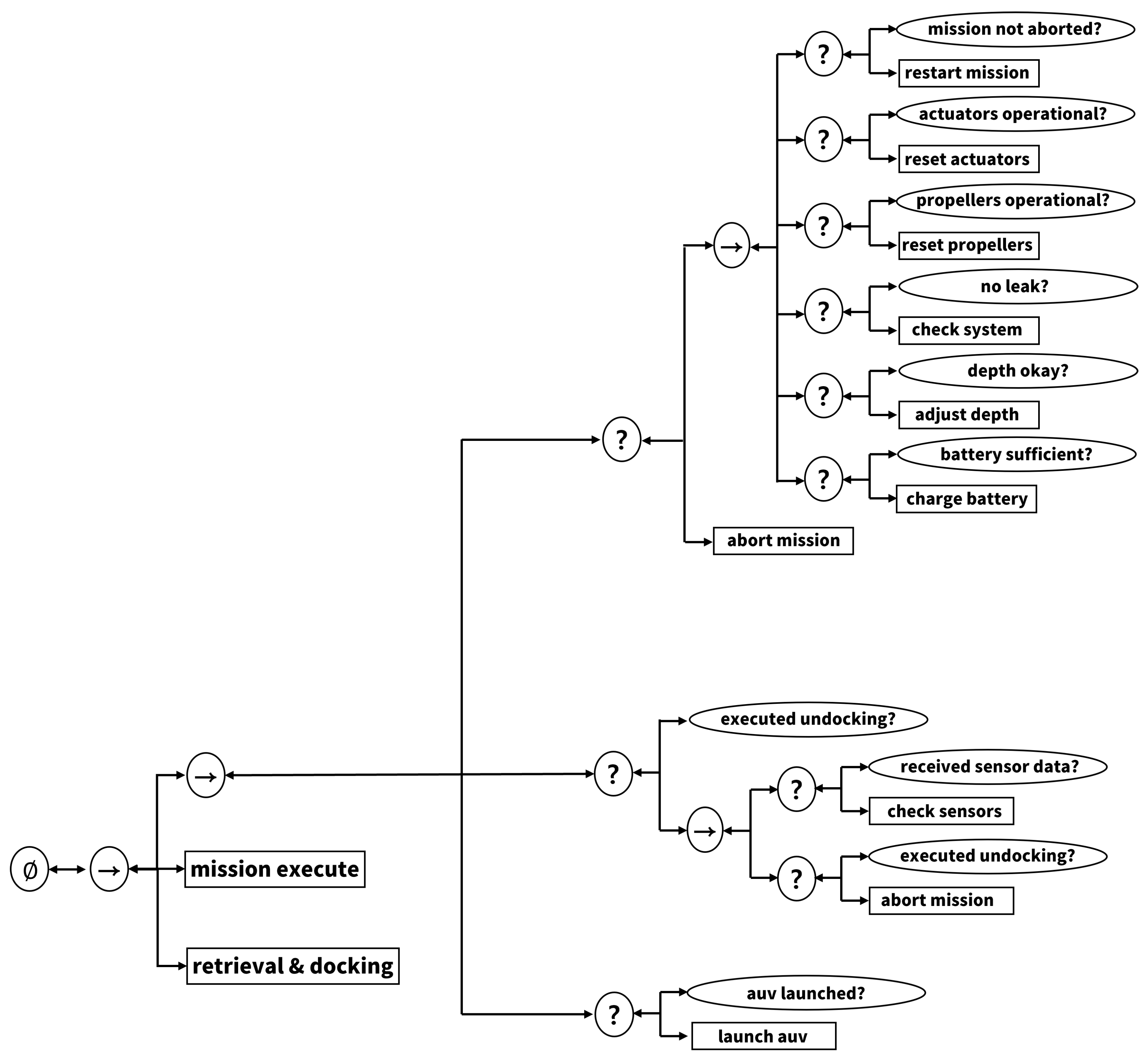
The primary objective of the launch phase is to ensure that the AUV safely undocks from the mothership and completes all essential pre-mission checks before commencing the primary mission. Figure 9 depicts the corresponding prepare-and-launch subtree, highlighting the sequence and fallback nodes that enforce these checks. The tree is organized around a top-level sequence node that triggers the critical tasks in order: issuing the launch command, verifying thruster and propeller operation, performing leak detection, checking depth limits, and confirming battery charge. Each test must return Success for the sequence to advance; if any anomaly (e.g., a faulty actuator, excessive depth, or low battery) is detected, execution is halted and routed to a diagnostic routine. Condition nodes also monitor whether the AUV has fully disengaged from the docking interface and whether sensor data streams are nominal. If undocking fails or a sensor fault is detected, a fallback branch issues a retry or, if necessary, aborts the launch. Only after all checks succeed and the AUV is clear of the mothership does control pass to the mission execution phase.

Figure 9.
Prepare and launch subtree. Sequence and fallback nodes manage pre-mission checks and safe undocking from the mothership.
By combining sequence and fallback nodes in this manner, the behavior tree framework improves the safety and reliability of the launch process, providing prompt exception handling and ensuring the AUV proceeds only under verified operational conditions.
3.1.2. Mission Execution
At the start of the mission execution phase, the behavior tree evaluates a primary condition node that determines overall system safety [15]. The complete mission execution subtree, including this safety gate and its contingency branches, is shown in Figure 10. This check covers a range of factors, including sensor health, communication status, temperature limits, and other criteria summarized in Table 2. If any abnormal condition is detected, the parent fallback node immediately triggers a safety action, such as evasive maneuvers or an emergency ascent, halting the mission to prevent further risk. This ensures that the AUV prioritizes rapid retrieval and system stabilization over continuing the mission in unsafe conditions. Next, a dedicated condition node verifies the stability of the navigation state by assessing the accuracy of position estimation, typically using data from the inertial navigation system (INS), global positioning system (GPS), or other localization sensors. If localization uncertainty is deemed too high, the mission is temporarily paused, allowing for recalibration or sensor checks before resuming operations. Mission synchronization is confirmed to ensure that all waypoints and operational scripts are correctly loaded and communicated. Should synchronization fail, an internal action node is automatically invoked to reload the data or receive updated mission parameters from remote sources.
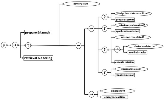
Figure 10.
Mission-execute subtree. Safety checks, waypoint loop and obstacle-avoidance fallback enable robust autonomous operation.
Table 2.
Safety parameter thresholds used by the behavior tree condition nodes.
Once all preparatory checks return success, the AUV proceeds to the core execute mission phase, performing navigation, exploration, and data acquisition tasks. Throughout the mission, the behavior tree continuously monitors for mission completion. In scenarios where obstacle detection is required, a high-priority fallback node checks for hazards using dedicated condition nodes. An avoidance action is immediately executed upon detecting an obstacle, recalculating a safe trajectory, or initiating evasive maneuvers as needed. This cycle of safety checks, navigation validation, mission synchronization, and dynamic obstacle handling repeats as the AUV sequentially visits each waypoint. The mission phase concludes when all tasks are completed, and the system transitions to the next stage. By strategically combining condition and fallback nodes, the behavior tree framework enables flexible and safe autonomous mission execution, ensuring the AUV can respond effectively to various operational contingencies.
3.1.3. Retrieval and Docking
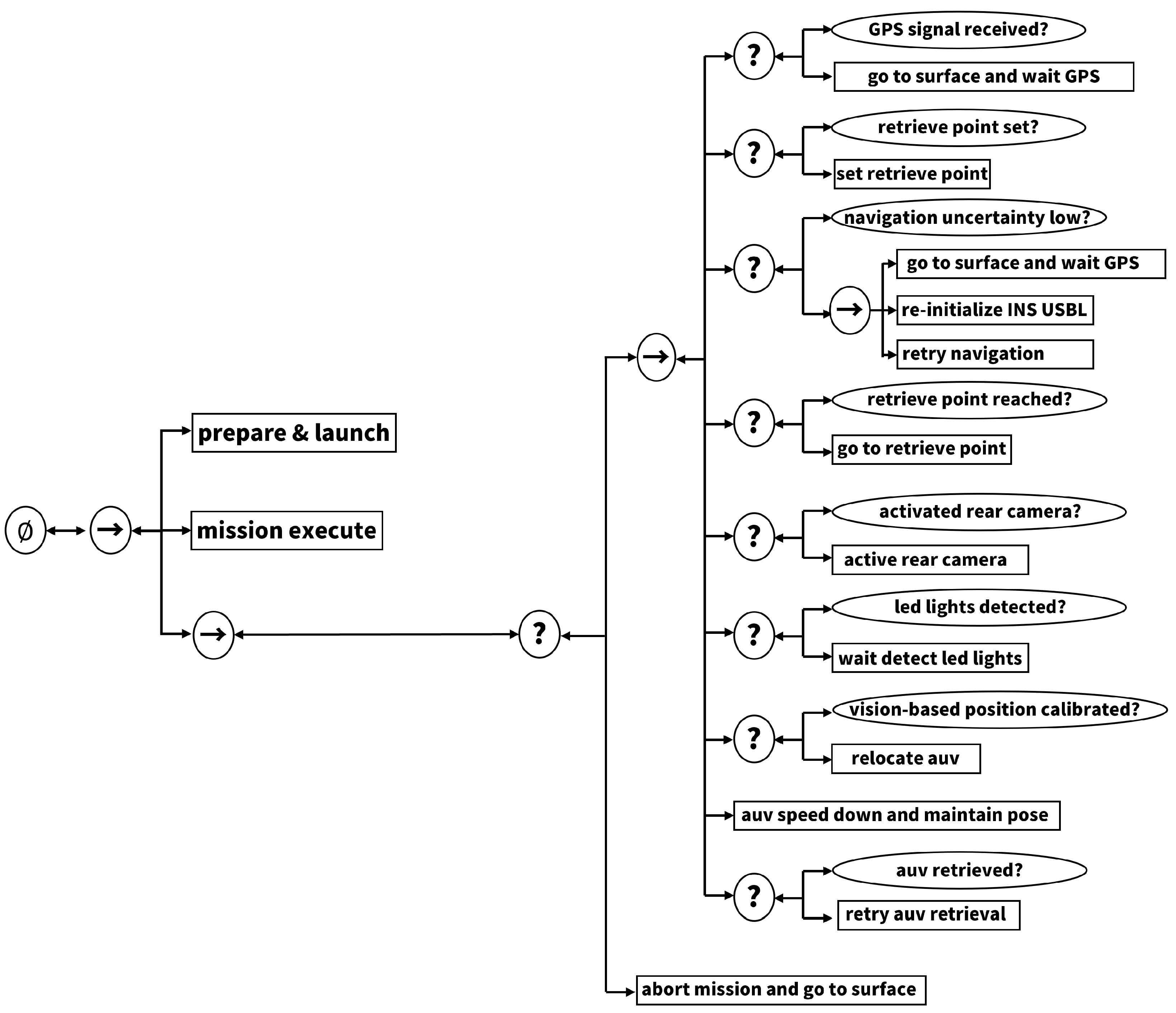
The retrieval phase focuses on safely recovering the AUV to the mothership after the mission is completed, with an emphasis on accurate localization and robust communication. Because both the mothership and the AUV remain submerged during this process, satellite-based GPS is generally unavailable, and the system primarily relies on ultrashort baseline (USBL) acoustic positioning for navigation, which provides an accuracy of approximately 1–3 m under typical operating conditions. The detailed retrieval and docking subtree, including these checks and contingency branches, is illustrated in Figure 11. The condition node continuously monitors the reliability and accuracy of USBL-based localization. Suppose the position uncertainty exceeds acceptable thresholds or acoustic communication becomes unstable. In that case, the fallback node immediately invokes contingency actions such as system reset (prepare system) or emergency ascent (abort and surface), temporarily surfacing the AUV to reacquire GPS-based position data if necessary. Navigation uncertainty is further monitored in real-time, and should localization confidence degrade, the AUV ascends to the surface to obtain a GPS fix before returning to the retrieval zone. Once reliable position information is restored, the AUV attempts to reach the designated retrieval point by executing the go-to retrieval point action, which is repeated until the AUV is confirmed to be within the required distance and bearing from the moving mothership.
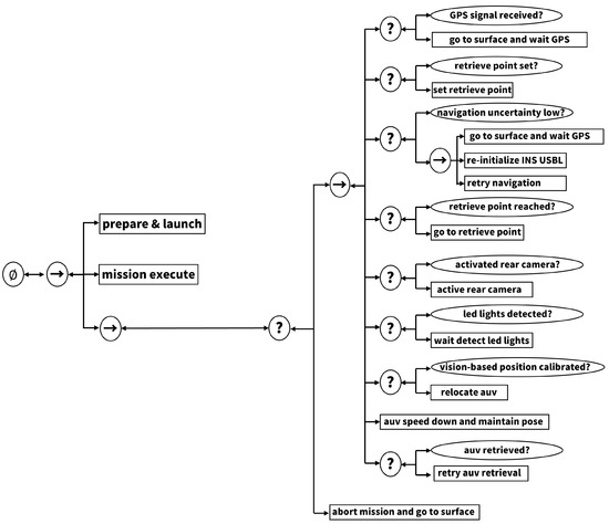
Figure 11.
Retrieval and docking subtree. USBL/GPS hand-over, LED-based visual alignment and final ingress sequence for dynamic docking.
To achieve precise docking during the final approach, four LEDs are installed in a square configuration at the bow of the moving mothership, serving as visual markers for navigation. The AUV utilizes its onboard vision system to detect these LEDs. It aligns its position and heading with the geometric center of the LED pattern, thereby correcting any accumulated navigation error from prior underwater transit [16,17]. Once the AUV is centered, it performs a controlled maneuver by moving 2.5 m east and 2.5 m down in the NED (North-East-Down) frame relative to the LED center, bringing it to the entrance of the docking tube. At this stage, the AUV gradually reduces its forward velocity, allowing for a smooth and safe entry into the docking tube while continuously compensating for the dynamic motion of the mothership. The condition node ‘auv is retrieved?’ confirms that the AUV has been fully recovered inside the mothership, thus marking the end of the mission. By combining multiple conditions and fallback nodes, the behavior tree structure enables the AUV to robustly address complex issues such as navigation errors and communication loss, leveraging acoustic and visual cues to maximize the safety and reliability of the retrieval operation under dynamic, real-world conditions.
3.2. Pose Estimation with an EKF
State estimation is carried out with an EKF that alternates prediction and measurement-update phases after an initial mean and covariance have been assigned [18]. The filter maintains both the best-guess state and its uncertainty, enabling statistically consistent fusion of high-rate inertial measurement unit (IMU) data with lower-rate absolute sensors such as GPS, Doppler velocity log (DVL), depth, and USBL. Here, we let the state vector contain the AUV’s position, velocity, and orientation, and all relevant variables are defined explicitly when introduced.
3.2.1. Prediction
The prediction step propagates state and covariance from to t using only IMU data. Let the state and IMU input at be
where are the position coordinates in the navigation frame, are velocities in the navigation frame, and are the quaternion elements representing orientation. The IMU input includes body-frame linear accelerations and angular rates .
Navigation–frame acceleration is
where is the rotation matrix converting vectors from body to navigation frame as defined by quaternion .
Over a step , the state prediction is
where ⊗ denotes quaternion multiplication, is the matrix exponential mapping angular rates to quaternion increment, and constructs the quaternion kinematic matrix from the angular rate vector .
The covariance prediction is
where captures IMU noise, bias drift, and unmodelled dynamics, and is the state transition Jacobian with respect to .
3.2.2. Measurement Update
When a measurement arrives, the prior is corrected as
where denotes the measurement model mapping state to expected measurement; is the measurement noise covariance; is the Kalman gain; and is the innovation covariance.
The Jacobian matrix is defined as
where is the identity matrix and is an zero matrix. rotates velocity from the navigation frame to the body frame.
To fuse DVL measurements, which are made in the body frame, with navigation-frame state, the rotation transformation and its transpose are used; this ensures alignment of the coordinate systems for proper sensor fusion. Note that heading errors in can result in long-term drift in navigation performance.
The measurement vector may contain GPS positions when surfaced, DVL velocity , depth sensor pressure-derived z, and USBL-based acoustic fixes.
Combined through Equations (6)–(9), these heterogeneous measurements produce a statistically consistent pose estimate for higher-level mission logic.
3.3. Obstacle Avoidance Using FLS-Based Potential Fields
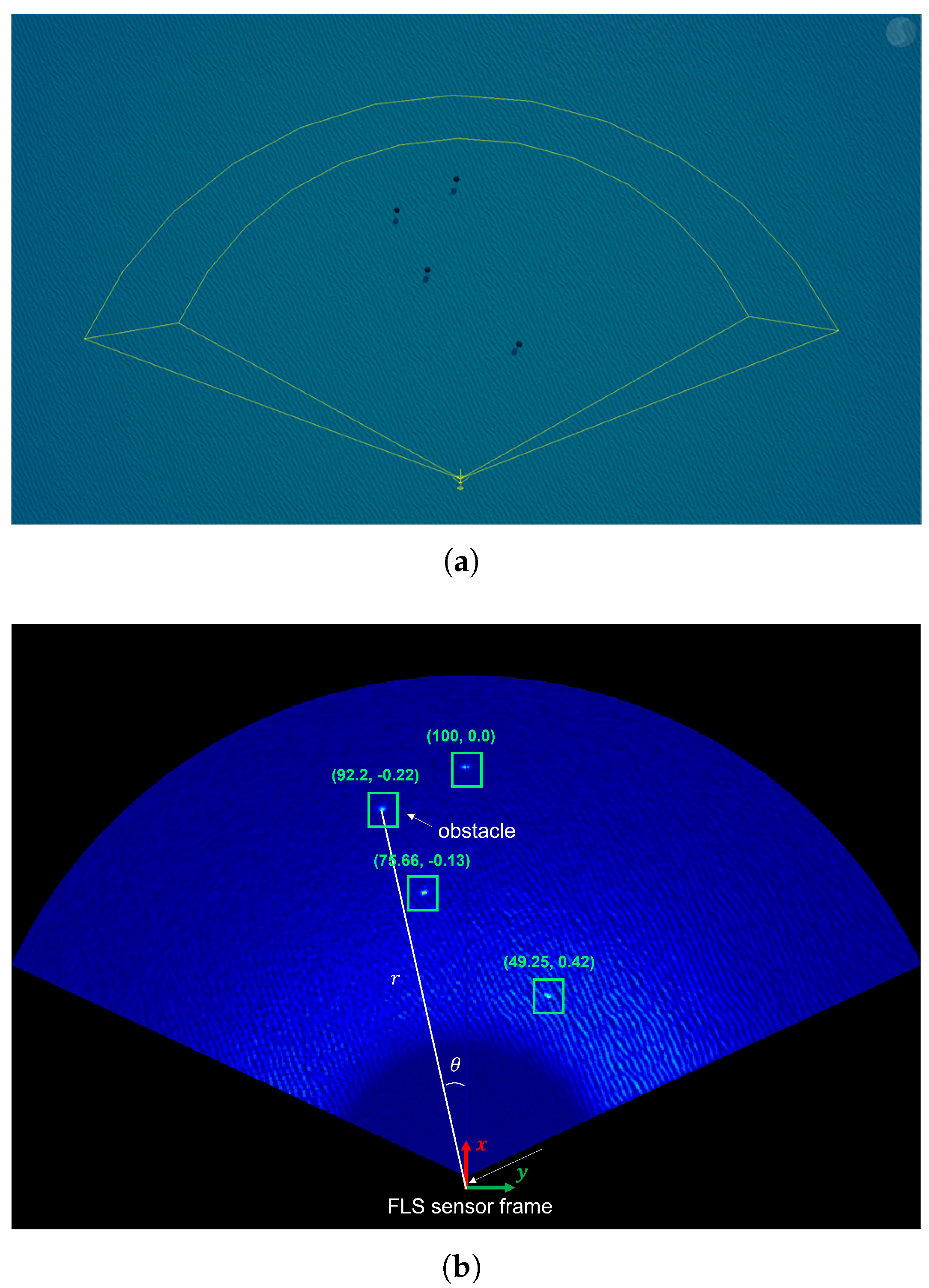
Obstacle information is obtained from the FLS, which returns, for each detected obstacle i, its polar coordinates in the AUV body frame (Figure 12) [19], where is the distance and is the bearing angle to obstacle i in the body-fixed frame.
where is the repulsive gain parameter, and is the influence threshold at which obstacles further than exert no repulsion.
where is the repulsive force from obstacle i, and the direction points away from obstacle i.
where N is the total number of detected obstacles.
where is the attractive gain, is the target position, and is the current AUV position. is the angle to the goal from the current position.
where is the total force vector combining attraction and repulsion.
where is the current heading of the AUV, is the desired heading determined by the total force , and is the heading error to be controlled.
where is the yaw controller proportional gain and is the commanded yaw rate.
where v is commanded surge speed, is the maximum surge speed, and denotes the distance to the nearest obstacle; as decreases, the AUV slows down for safety.

Figure 12.
FLS obstacle detection. (a) Raw sonar image. (b) Detection result: Each obstacle is enclosed by a green bounding box, and its range and bearing are annotated.
In the artificial potential field (APF) formulation [20], the mission goal is treated as an attractive source, whereas every obstacle contributes the repulsive potential of Equation (11). The negative gradient yields the single-obstacle force in Equation (12), and summing these forces gives the total repulsive term of Equation (13). Adding the attractive force of Equation (14) produces the net force in Equation (15), whose direction defines the desired yaw angle . The heading error in Equation (16) is cancelled by the proportional yaw-rate command of Equation (17), and the surge-speed law in Equation (18) scales with the nearest obstacle range , slowing the AUV in confined spaces. This APF controller is computationally lightweight yet effectively merges goal seeking with real-time avoidance of FLS-detected hazards.
4. Simulation
4.1. Simulation Setup
This study implemented a docking scenario between an AUV and a moving mothership by integrating a physics-based simulator with ROS Noetic (Ubuntu 20.04). For the simulation environment, the Stonefish simulator (Version 1.5) [21], widely used for marine robotics research, was employed with the Bullet physics engine to model hydrodynamic drag, buoyancy, and collision effects. This setup enables the realistic reproduction of diverse and dynamic behaviors commonly encountered in marine environments. It enables the real-time integration of sensor and control nodes in ROS, creating an experimental platform that resembles actual field operations.
Both the AUV and mothership models were designed to be close to real-world scale using Autodesk Inventor for 3D modeling, then imported into the Stonefish simulator for visualization and dynamic simulation. The mothership model was configured with an overall length of approximately 89.4 m and a diameter of 9.6 m, featuring a horizontal launch tube near the bow to facilitate AUV ingress and egress. For simplicity, the propulsion system was implemented with a single thruster and rudder, allowing for straight-line motion and heading adjustments in the simulated environment. The AUV model includes both vertical and horizontal thrusters arranged in a vectored configuration, enabling full 6-DOF motion. These thrusters are symmetrically distributed along the hull and are not placed end-to-end, ensuring stable control authority in confined spaces.
The AUV is a compact platform measuring 2.5 m in length and approximately 0.2 m in diameter. It is equipped with a rear surge thruster for forward propulsion and pairs of horizontal and vertical thrusters, enabling maneuvering in both vertical and lateral directions. Detailed sensor and actuator specifications for both the AUV and mothership platforms used in the simulation are provided in Appendix A. To ensure physically plausible motion, the hydrodynamic effects acting on both the AUV and the mothership are approximated by the Bullet physics engine within the Stonefish simulator. Instead of explicitly defining hydrodynamic coefficients such as linear drag or added mass, the simulator derives forces from the geometry, volume, and inertial properties of each body. This enables realistic underwater dynamics based on high-level physical modeling, eliminating the need for manual tuning of specific coefficients.
Both models are subject to approximated hydrodynamic effects via the Bullet physics engine, with parameters such as mass, volume, and center of gravity set to closely match those of real marine AUVs, ensuring realistic dynamic behavior.
Within the simulation, the mothership and AUV interact physically in the Stonefish environment, with key variables such as AUV position, orientation, and thruster output monitored in real-time via ROS.
4.2. Results
In this section, we present simulation results demonstrating the effectiveness of the proposed behavior tree-based control architecture. The simulation environment is configured with a water depth of 50 m, and the AUV is tasked with traversing a mission route exceeding 3 km, during which it must avoid randomly positioned obstacles. The mothership advances along a prescribed path, continuously adjusting its heading throughout the scenario. To more accurately reflect underwater operating conditions, a constant ocean current was incorporated into the simulation environment. Specifically, the current was modeled with a velocity of 0.2 m/s in the positive x-direction and 0.01 m/s in the positive y-direction. These values were selected to simulate mild but non-negligible environmental disturbances affecting vehicle navigation.
Two main scenarios were investigated. The first scenario evaluates system performance when all behavior tree nodes function correctly, resulting in a nominal mission execution. The second scenario investigates how the system responds to a fault occurring in one of the behavior tree nodes, thereby validating the architecture’s fault tolerance and exception handling capabilities.
4.2.1. Scenario 1: Mission Success Under Nominal Conditions
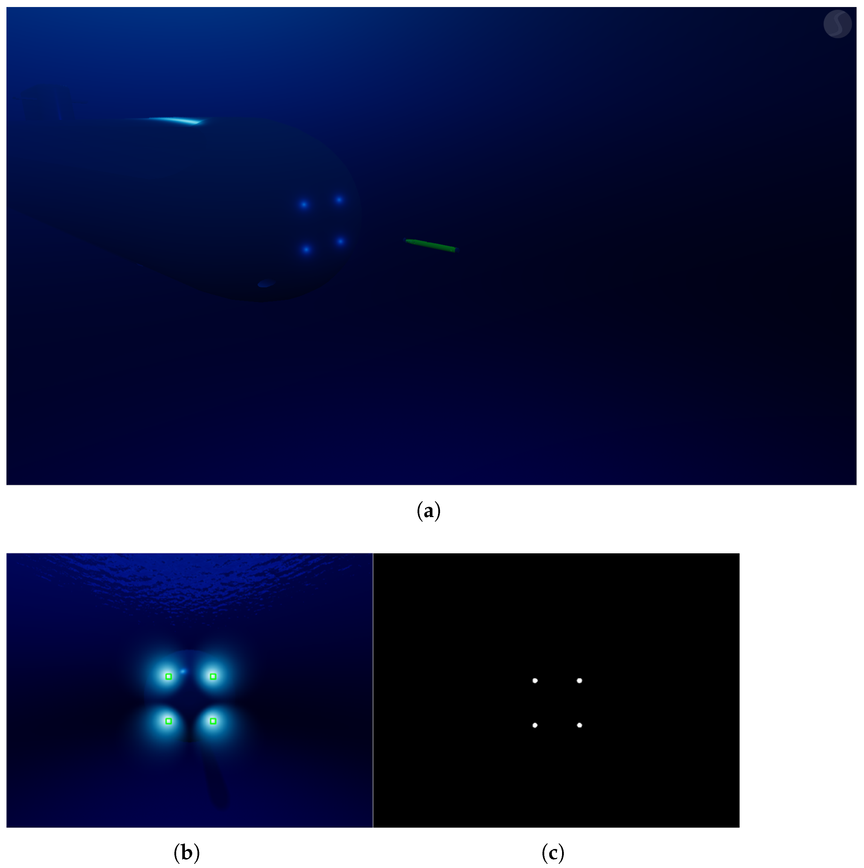
In the nominal operation scenario result shown in Figure 13, all behavior tree nodes across the launch, mission execution, and retrieval phases function as intended, consistently returning success. The mothership continuously changes its heading while moving forward throughout the mission. The AUV initially navigates using USBL-based acoustic positioning and INS data to track its relative position and heading concerning the moving mothership. As the AUV enters the retrieval phase, it switches to a vision-based alignment mode that detects the LED markers mounted at the mouth of the retrieval tube. Figure 14 illustrates the visual alignment process. Figure 14a gives an overview of the retrieval scene, showing the AUV, the moving mothership, and the LED targets at the tube entrance. Figure 14b is the image captured by the AUV’s rear-facing camera, where the LED markers are detected. Figure 14c shows the binary segmentation mask derived from those detections, from which the LED centroids are calculated for fine positioning. Using these cues, the AUV adjusts its heading and lateral offset, aligns with the moving mothership, and glides into the retrieval tube to complete docking. The results confirm that the proposed behavior tree framework delivers robust and reliable mission execution, even during dynamic cooperative maneuvers.
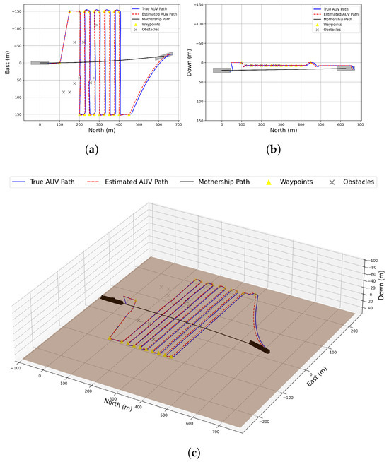
Figure 13.
Result of nominal mission. (a) XY view. (b) XZ view. (c) Three-dimensional trajectory of AUV and mothership.

Figure 14.
LED-based visual alignment. (a) Overview of the retrieval scene. (b) Rear-camera image with detected LED markers. (c) Binary segmentation mask highlighting the LEDs.
4.2.2. Scenario 2: Fault Response and Exception Handling
In the second scenario, the result shown in Figure 15, mission termination is triggered by a low-battery condition rather than a hardware fault. Once the AUV is launched, a Parallel node supervises two concurrent tasks: (i) waypoint navigation and (ii) real-time battery monitoring via the BatterySufficient condition node. The critical threshold is fixed at 30 % (Table 2). When the state of charge drops below this value, BatterySufficient returns Success. Because the parallel node follows a success on one policy, this single success suffices to halt the mission branch and propagate success upward, prompting the higher-level tree to abort remaining waypoints and switch to the retrieval and docking subtree.
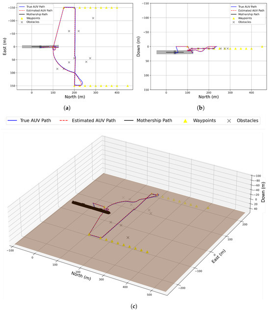
Figure 15.
Result of battery abort mission. (a) XY view. (b) XZ view. (c) Three-dimensional path after low-battery abort.
The resulting handover is immediate and orderly. The AUV ascends if necessary, navigates to the rendezvous point, and docks with the moving mothership. Figure 16 summarizes the full execution flow from nominal operation through mission completion, battery-triggered abort, and final retrieval, demonstrating how the parallel node architecture enables a real-time, battery-aware transition without hard-coded exception handlers.
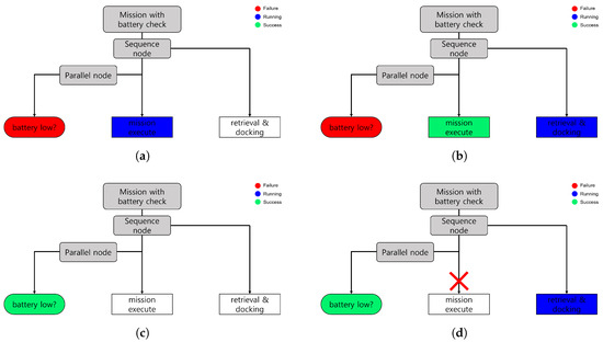
Figure 16.
Behavior tree response to battery events. (a) Nominal running with battery above 30%. (b) Normal mission completion. (c) Low-battery trigger: Battery low? returns Success. (d) Retrieval subtree running after handover.
4.3. Discussion
The simulation results show that the proposed behavior tree framework delivers robust and flexible mission planning for collaborative AUV–mothership operations. Its modular structure cleanly separates safety checks, navigation validation, and mission execution, so faults stay localized and the vehicle can resume its tasks with minimal disruption. Because mission logic is composed of reusable BT nodes, new behaviors can be added or existing ones modified without rewriting the entire control scheme, making the approach adaptable to diverse mission profiles and future platform upgrades.
5. Conclusions
This work proposed a behavior tree-based mission planning and control architecture to enable safe and flexible collaboration between AUVs and a moving mothership. By decomposing the mission into launch, mission execution, and retrieval phases, the framework supports efficient task management and rapid response to unexpected events. Simulation results confirmed the reliability and effectiveness of the approach, particularly in vision-based docking and dynamic obstacle avoidance scenarios. The modularity and scalability inherent in the behavior tree design further enhance the system’s adaptability to various operational contexts.
The proposed architecture was validated primarily through comprehensive simulation studies. As a next step, experimental verification with real, on-site AUV deployments is required further to assess the practical robustness and reliability of the system. While the simulations demonstrated the framework’s ability to manage multiple AUVs, further research is needed to verify scalability for larger fleets and more complex, heterogeneous mission profiles. Comparative analyses with other mission planning approaches, such as finite state machines and decision trees, are also planned to quantitatively evaluate the benefits and trade-offs of the behavior tree-based method. Additional future directions include expanding to more complex mission phase structures, adapting to heterogeneous vehicle teams, and further improving reproducibility and real-world deployment guidelines.
Author Contributions
Conceptualization, J.J. and S.C.; methodology, J.J. and S.C.; software, J.J. and S.C.; validation, J.J. and S.C.; formal analysis, J.J. and S.C.; investigation, J.J. and S.C.; resources, J.J.; data curation, S.C.; writing—original draft preparation, S.C.; writing—review and editing, J.J. and S.C.; visualization, S.C.; supervision, J.J.; project administration, J.J.; funding acquisition, J.J. All authors have read and agreed to the published version of the manuscript.
Funding
This research was supported by Korea Institute of Marine Science & Technology Promotion (KIMST) funded by the Ministry of Oceans and Fisheries (RS-2023-00256122). This research was also supported by the Challengeable Future Defense Technology Research and Development Program through the Agency for Defense Development (ADD) funded by the Defense Acquisition Program Administration (DAPA) in 2025 (No. 915071101).
Data Availability Statement
The original contributions presented in the study are included in the article; further inquiries can be directed to the corresponding author.
Conflicts of Interest
The authors declare no conflicts of interest.
Appendix A. Sensor and Actuator Specifications
Appendix A.1. AUV Platform
- IMU (Inertial Measurement Unit): 3-axis gyro and accelerometer, angular rate noise: 0.02 rad/s, acceleration noise: 0.05 m/s2
- Depth Sensor: Pressure-based depth estimation, accuracy: ±0.1 m
- DVL (Doppler Velocity Log): Measures body-frame velocity, accuracy: ±0.2 m/s
- USBL (Acoustic Positioning): Provides global position estimate, accuracy: ±2.0 m
- Camera (for docking): Monochrome 2D vision, resolution: 640 × 480 px
- Thrusters: 6-DOF vectored configuration, max thrust per axis: ±30 N
Appendix A.2. Mothership Platform
- USBL Transmitter: Assumed equivalent to AUV receiver, accuracy: ±2.0 m
- Docking Lights: 4-point LED pattern, visible range: 10–15 m
- Propulsion and Control: Dual rudder and horizontal plane for heading and depth adjustment
Note: All specifications are approximate values based on typical simulation parameters for underwater vehicles.
References
- Nicholson, J.; Healey, A. The present state of autonomous underwater vehicle (AUV) applications and technologies. Mar. Technol. Soc. J. 2008, 42, 44–51. [Google Scholar] [CrossRef]
- Zhang, J.; Han, G.; Sha, J.; Qian, Y.; Liu, J. AUV-assisted subsea exploration method in 6G enabled deep ocean based on a cooperative pac-men mechanism. IEEE Trans. Intell. Transp. Syst. 2021, 23, 1649–1660. [Google Scholar] [CrossRef]
- Jones, D.; Gates, A.; Huvenne, V.; Phillips, A.; Bett, B. Autonomous marine environmental monitoring: Application in decommissioned oil fields. Sci. Total. Environ. 2019, 668, 835–853. [Google Scholar] [CrossRef] [PubMed]
- Wang, C.; Cheng, C.; Yang, D.; Pan, G.; Zhang, F. AUV planning and calibration method considering concealment in uncertain environments. Front. Mar. Sci. 2023, 10, 1228306. [Google Scholar] [CrossRef]
- Zhang, Y.; Wang, Q.; Shen, Y.; Dai, N.; He, B. Multi-AUV cooperative control and autonomous obstacle avoidance study. Ocean. Eng. 2024, 304, 117634. [Google Scholar] [CrossRef]
- Sprague, C.; Özkahraman, Ö.; Munafo, A.; Marlow, R.; Phillips, A.; Ögren, P. Improving the modularity of AUV control systems using behavior trees. In Proceedings of the 2018 IEEE/OES Autonomous Underwater Vehicle Workshop (AUV), Porto, Portugal, 6–9 November 2018; IEEE: Piscataway, NJ, USA, 2018; pp. 1–6. [Google Scholar]
- Szczotka, M. AUV launch & retrieval handling simulation on a rough sea. Ocean Eng. 2022, 246, 110509. [Google Scholar]
- Yan, Z.; Gong, P.; Zhang, W. Dynamic docking technology between AUV and mobile mothership. In Proceedings of the 2020 Chinese Control and Decision Conference (CCDC), Hefei, China, 22–24 August 2020; IEEE: Piscataway, NJ, USA, 2020; pp. 3045–3049. [Google Scholar]
- Chen, Y.; Guo, X.; Luo, G.; Liu, G. A formation control method for AUV group under communication delay. Front. Bioeng. Biotechnol. 2022, 10, 848641. [Google Scholar] [CrossRef] [PubMed]
- Yu, C.; Xiang, X.; Lapierre, L.; Zhang, Q. Robust magnetic tracking of subsea cable by AUV in the presence of sensor noise and ocean currents. IEEE J. Ocean. Eng. 2017, 43, 311–322. [Google Scholar] [CrossRef]
- Savkin, A.; Verma, S.; Anstee, S. Optimal navigation of an unmanned surface vehicle and an autonomous underwater vehicle collaborating for reliable acoustic communication with collision avoidance. Drones 2022, 6, 27. [Google Scholar] [CrossRef]
- Colledanchise, M.; Ögren, P. Behavior Trees in Robotics and AI: An Introduction; CRC Press: Boca Raton, FL, USA, 2018. [Google Scholar]
- Ögren, P.; Sprague, C. Behavior trees in robot control systems. Annu. Rev. Control Robot. Auton. Syst. 2022, 5, 81–107. [Google Scholar] [CrossRef]
- Gollücke, V.; Lange, D.; Hahn, A.; Schweigert, S. Behavior tree based knowledge reasoning for intelligent vessels in maritime traffic simulations. In Proceedings of the ECMS, Wilhelmshaven, Germany, 22–25 May 2018; pp. 105–113. [Google Scholar]
- Palomeras, N.; El-Fakdi, A.; Carreras, M.; Ridao, P. COLA2: A control architecture for AUVs. IEEE J. Ocean. Eng. 2012, 37, 695–716. [Google Scholar] [CrossRef]
- Kobatake, K.; Okamoto, A.; Sasano, M.; Inaba, S.; Fujiwara, T. Docking control method using LEDs detection by hovering AUV “Hobalin” for deep-sea research. In Proceedings of the OCEANS 2024–Halifax, Halifax, NS, Canada, 23–26 September 2024; pp. 1–6. [Google Scholar]
- Fan, S.; Liu, C.; Li, B.; Xu, Y.; Xu, W. AUV docking based on USBL navigation and vision guidance. J. Mar. Sci. Technol. 2019, 24, 673–685. [Google Scholar] [CrossRef]
- Armstrong, B.; Wolbrecht, E.; Edwards, D. AUV navigation in the presence of a magnetic disturbance with an extended Kalman filter. In Proceedings of the OCEANS’10 IEEE Sydney, Sydney, NSW, Australia, 24–27 May 2010; IEEE: Piscataway, NJ, USA, 2010; pp. 1–6. [Google Scholar]
- Zacchini, L.; Franchi, M.; Manzari, V.; Pagliai, M.; Secciani, N.; Topini, A.; Ridolfi, A. Forward-looking sonar CNN-based automatic target recognition: An experimental campaign with FeelHippo AUV. In Proceedings of the 2020 IEEE/OES Autonomous Underwater Vehicles Symposium (AUV), St. Johns, NL, Canada, 30 September–2 October 2020; IEEE: Piscataway, NJ, USA, 2020; pp. 1–6. [Google Scholar]
- Fan, X.; Guo, Y.; Liu, H.; Wei, B.; Lyu, W. Improved artificial potential field method applied for AUV path planning. Math. Probl. Eng. 2020, 2020, 6523158. [Google Scholar] [CrossRef]
- Cieślak, P. Stonefish: An advanced open-source simulation tool designed for marine robotics, with a ROS interface. In Proceedings of the OCEANS 2019—Marseille, Marseille, France, 17–20 June 2019; IEEE: Piscataway, NJ, USA, 2019; pp. 1–6. [Google Scholar]


Disclaimer/Publisher’s Note: The statements, opinions and data contained in all publications are solely those of the individual author(s) and contributor(s) and not of MDPI and/or the editor(s). MDPI and/or the editor(s) disclaim responsibility for any injury to people or property resulting from any ideas, methods, instructions or products referred to in the content. |
© 2025 by the authors. Licensee MDPI, Basel, Switzerland. This article is an open access article distributed under the terms and conditions of the Creative Commons Attribution (CC BY) license (https://creativecommons.org/licenses/by/4.0/).